

Page 1

MPA 601-70V and
MPA 601-100V
60W Analog Power Amplifiers
User Guide
Power Amplifiers
68-2512-01 Rev. B
01 17
Page 2

Safety Instructions
Safety Instructions • English
WARNING: This symbol, , when used on the product, is intended to
alert the user of the presence of uninsulated dangerous voltage within
the product’s enclosure that may present a risk of electric shock.
ATTENTION: This symbol, , when used on the product, is intended
to alert the user of important operating and maintenance (servicing)
instructions in the literature provided with the equipment.
For information on safety guidelines, regulatory compliances, EMI/EMF
compatibility, accessibility, and related topics, see the Extron Safety and
Regulatory Compliance Guide, part number 68-290-01, on the Extron
website, www.extron.com.
Sicherheitsanweisungen • Deutsch
WARNUNG: Dieses Symbol auf dem Produkt soll den Benutzer
darauf aufmerksam machen, dass im Inneren des Gehäuses dieses
Produktes gefährliche Spannungen herrschen, die nicht isoliert sind und
die einen elektrischen Schlag verursachen können.
VORSICHT: Dieses Symbol auf dem Produkt soll dem Benutzer in
der im Lieferumfang enthaltenen Dokumentation besonders wichtige
Hinweise zur Bedienung und Wartung (Instandhaltung) geben.
Weitere Informationen über die Sicherheitsrichtlinien, Produkthandhabung,
EMI/EMF-Kompatibilität, Zugänglichkeit und verwandte Themen finden Sie in
den Extron-Richtlinien für Sicherheit und Handhabung (Artikelnummer
68-290-01) auf der Extron-Website, www.extron.com.
Instrucciones de seguridad • Español
ADVERTENCIA: Este símbolo, , cuando se utiliza en el producto,
avisa al usuario de la presencia de voltaje peligroso sin aislar dentro del
producto, lo que puede representar un riesgo de descarga eléctrica.
ATENCIÓN: Este símbolo, , cuando se utiliza en el producto, avisa
al usuario de la presencia de importantes instrucciones de uso y
mantenimiento recogidas en la documentación proporcionada con el
equipo.
Para obtener información sobre directrices de seguridad, cumplimiento
de normativas, compatibilidad electromagnética, accesibilidad y temas
relacionados, consulte la Guía de cumplimiento de normativas y seguridad
de Extron, referencia 68-290-01, en el sitio Web de Extron, www.extron.com.
Instructions de sécurité • Français
AVERTISSEMENT : Ce pictogramme, , lorsqu’il est utilisé sur le
produit, signale à l’utilisateur la présence à l’intérieur du boîtier du
produit d’une tension électrique dangereuse susceptible de provoquer
un choc électrique.
ATTENTION : Ce pictogramme, , lorsqu’il est utilisé sur le produit,
signale à l’utilisateur des instructions d’utilisation ou de maintenance
importantes qui se trouvent dans la documentation fournie avec le
matériel.
Pour en savoir plus sur les règles de sécurité, la conformité à la
réglementation, la compatibilité EMI/EMF, l’accessibilité, et autres sujets
connexes, lisez les informations de sécurité et de conformité Extron, réf.
68-290-01, sur le site Extron, www.extron.com.
Istruzioni di sicurezza • Italiano
AVVERTENZA: Il simbolo, , se usato sul prodotto, serve ad
avvertire l’utente della presenza di tensione non isolata pericolosa
all’interno del contenitore del prodotto che può costituire un rischio di
scosse elettriche.
ATTENTZIONE: Il simbolo, , se usato sul prodotto, serve ad
avvertire l’utente della presenza di importanti istruzioni di funzionamento
e manutenzione nella documentazione fornita con l’apparecchio.
Per informazioni su parametri di sicurezza, conformità alle normative,
compatibilità EMI/EMF, accessibilità e argomenti simili, fare riferimento
alla Guida alla conformità normativa e di sicurezza di Extron, cod. articolo
68-290-01, sul sito web di Extron, www.extron.com.
Instrukcje bezpieczeństwa • Polska
OSTRZEŻENIE: Ten symbol, , gdy używany na produkt, ma na celu
poinformować użytkownika o obecności izolowanego i niebezpiecznego
napięcia wewnątrz obudowy produktu, który może stanowić zagrożenie
porażenia prądem elektrycznym.
UWAGI: Ten symbol, , gdy używany na produkt, jest przeznaczony do
ostrzegania użytkownika ważne operacyjne oraz instrukcje konserwacji
(obsługi) w literaturze, wyposażone w sprzęt.
Informacji na temat wytycznych w sprawie bezpieczeństwa, regulacji
wzajemnej zgodności, zgodność EMI/EMF, dostępności i Tematy pokrewne,
zobacz Extron bezpieczeństwa i regulacyjnego zgodności przewodnik, część
numer 68-290-01, na stronie internetowej Extron, www.extron.com.
Инструкция по технике безопасности • Русский
ПРЕДУПРЕЖДЕНИЕ: Данный символ, , если указан
на продукте, предупреждает пользователя о наличии
неизолированного опасного напряжения внутри корпуса
продукта, которое может привести к поражению
электрическим током.
ВНИМАНИЕ: Данный символ, , если указан на продукте,
предупреждает пользователя о наличии важных инструкций
по эксплуатации и обслуживанию в руководстве,
прилагаемом к данному оборудованию.
Для получения информации о правилах техники безопасности,
соблюдении нормативных требований, электромагнитной
совместимости (ЭМП/ЭДС), возможности доступа и других
вопросах см. руководство по безопасности и соблюдению
нормативных требований Extron на сайте Extron: ,
www.extron.com, номер по каталогу - 68-290-01.
安全说明 • 简体中文
警告: 产品上的这个标志意在警告用户该产品机壳内有暴露的危险 电压,
有触电危险。
注意: 产品上的这个标志意在提示用户设备随附的用户手册中有
重要的操作和维护(维修)说明。
关于我们产品的安全指南、遵循的规范、EMI/EMF 的兼容性、无障碍
使用的特性等相关内容,敬请访问 Extron 网站 , www.extron.com,参见
Extron 安全规范指南,产品编号 68-290-01。
Page 3

安全記事 • 繁體中文
警告: 若產品上使用此 符號,是為了提醒使用者,產品機殼內存 在著
可能會導致觸電之風險的未絕緣危險電壓。
注意 若產品上使用此符號,是為了提醒使用者,設備隨附的用戶手冊中有
重要的操作和維護(維修)説明。
有關安全性指導方針、法規遵守、EMI/EMF 相容性、存取範圍和相關主題的詳細資
訊,請瀏覽 Extron 網站:www.extron.com,然後參閱《Extron 安全性與法規
遵守手冊》,準則編號 68-290-01。
安全上のご注意 • 日本語
警告: この記 号 が製品上に表示されている場合は、筐体内に絶縁されて
いない高電圧が流れ、感電の危険があることを示しています。
注意:この記号 が製品上に表示されている場合は、本機の取扱説明書に
記載されている重要な操作と保守( 整備)の 指示についてユーザーの注 意
を喚起するものです。
安全上のご注意、法規厳守、EMI/EMF適合性、その他の関連項目に
つ い て は 、エ クスト ロ ンの ウェブ サ イト www.extron.com よ り 『 Extron Safety
and Regulatory Compliance Guide』 ( P/N 68-290-01) をご覧ください。
안전 지침 • 한국어
경고: 이 기호 가 제품에 사용될 경우, 제품의 인클로저 내에 있는
접지되지 않은 위험한 전류로 인해 사용자가 감전될 위험이 있음을
경고합니다.
주의: 이 기호 가 제품에 사용될 경우, 장비와 함께 제공된 책자에 나와
있는 주요 운영 및 유지보수(정비) 지침을 경고합니다.
안전 가이드라인, 규제 준수, EMI/EMF 호환성, 접근성, 그리고 관련 항목에
대한 자세한 내용은 Extron 웹 사이트(www.extron.com)의 Extron 안전 및
규제 준수 안내서, 68-290-01 조항을 참조하십시오.
Copyright
© 2017 Extron Electronics. All rights reserved.
Trademarks
All trademarks mentioned in this guide are the properties of their respective owners.
The following registered trademarks(
®
), registered service marks(
ExtronElectronics (see the current list of trademarks on the Terms of Use page at www.extron.com):
Extron, AVTrac, Cable Cubby, ControlScript, CrossPoint, DTP, eBUS, EDID Manager, EDID Minder, Flat Field, FlexOS, Global Configurator,
GlobalScripter, GlobalViewer, Hideaway, Inline, IPIntercom, IPLink, KeyMinder, LinkLicense, LockIt, MediaLink, MediaPort, NetPA,
PlenumVault, PoleVault, PowerCage, PURE3, Quantum, SoundField, SpeedMount, SpeedSwitch, SystemINTEGRATOR, TeamWork,
TouchLink, V-Lock, VersaTools, VN-Matrix, VoiceLift, WallVault, WindoWall, XTP, and XTPSystems
Registered Service Mark
(SM)
: S3 Service Support Solutions
AAP, AFL (Accu-RateFrameLock), ADSP(Advanced Digital Sync Processing), Auto-Image, CableCover, CDRS(ClassD Ripple
Suppression), DDSP(Digital Display Sync Processing), DMI (DynamicMotionInterpolation), DriverConfigurator, DSPConfigurator,
DSVP(Digital Sync Validation Processing), eLink, Entwine, EQIP, EverLast, FastBite, FOX, FOXBOX, IP Intercom HelpDesk, HyperLane,
MAAP, MicroDigital, Opti-Torque, ProDSP, QS-FPC(QuickSwitch Front Panel Controller), Room Agent, Scope-Trigger, ShareLink, SIS,
SimpleInstructionSet, Skew-Free, SpeedNav, Triple-Action Switching, True4K, Vector™ 4K , WebShare, XTRA, ZipCaddy, and ZipClip
SM
), and trademarks(TM) are the property of RGBSystems, Inc. or
Registered Trademarks
Trademarks (™
)
(®)
Page 4

FCC Class B Notice
NOTE: This device complies with part 15 of the FCC rules. Operation is subject to
the following two conditions: (1) This device may not cause harmful interference,
and (2) This device must accept any interference received, including interference
that may cause undesired operation.
This equipment has been tested and found to comply with the limits for a Class B digital
device, pursuant to part15 of the FCC rules. These limits provide reasonable protection
against harmful interference in a residential installation. This equipment generates, uses,
and can radiate radio frequency energy and, if not installed and used in accordance with
the instructions, may cause harmful interference to radio communications. There is no
guarantee that interference will not occur. If this equipment does cause interference to radio
or television reception, which can be determined by turning the equipment off and on, you
are encouraged to try to correct the interference by one or more of the following measures:
• Reorient or relocate the receiving antenna.
• Increase the separation between the equipment and receiver.
• Connect the equipment into an outlet on a circuit different from that to which the
receiver is connected.
• Consult the dealer or an experienced radio/TV technician for help.
In order to maintain compliance with FCC regulations, shielded cables must be used with
this equipment. Operation with non-approved equipment or unshielded cables is likely to
result in interference to radio and TV reception. The user is cautioned that changes and
modifications made to the equipment without the approval of the manufacturer could void
the user’s authority to operate this equipment.
This Class B digital apparatus complies with Canadian ICES-003.
Cet appareil numérique de la classe B est conforme à la norme NMB-003 du Canada.
ATTENTION:
• This equipment complies with FCC radiation exposure limits set forth for an
uncontrolled environment. This equipment should be installed and operated
with minimum distance 20 cm (7.9 inches) between the radiator and your body.
• Cet équipement est conforme aux limites de radiation de la FCC établies pour
un environnement non géré. Il doit être installé et contrôlé à une distance
minimale de 20 cm (7,87 inches) entre le radiateur et votre corps.
NOTE: For more information on safety guidelines, regulatory compliances, EMI/
EMF compatibility, accessibility, and related topics see the Extron Safety and
Regulatory Compliance Guide on the Extron website.
Page 5

Conventions Used in this Guide
Notifications
The following notifications are used in this guide:
ATTENTION:
• Risk of property damage.
• Risque de dommages matériels.
NOTE: A note draws attention to important information.
TIP: A tip provides a suggestion to make working with the application easier.
Specifications Availability
Product specifications are available on the Extron website, www.extron.com.
Extron Glossary of Terms
A glossary of terms is available at http://www.extron.com/technology/glossary.aspx.
Page 6

Contents
Introduction ................................................1
About this Guide .................................................. 1
Important Safety Instructions ............................... 1
About the MPA 601-70V and MPA 601-100V ...... 2
Features .............................................................. 2
Application Diagram ............................................ 4
Installation .................................................. 5
Rear Panel Connections ...................................... 5
Operation..................................................10
Front Panel Features ......................................... 10
Setting Input Level ............................................. 10
Setting Bass and Treble ..................................... 11
Remote Control Operation ................................. 11
Controlling Multiple Amplifiers with One
Remote Controller ........................................ 12
Control Options ............................................. 13
Troubleshooting ................................................. 14
Amplifier Fails to Exit Standby Mode
Promptly ....................................................... 14
Amplifier Enters Standby Mode Too Early ....... 14
Mounting ..................................................15
Plenum Placement ............................................ 15
Tabletop Placement ........................................... 15
Rack Mounting .................................................. 16
Under-Desk, Through-Desk, and Projector
Mounting .......................................................... 16
viMPA 601 • Table of Contents
Page 7

Introduction
This section provides an overview of the MPA 601-70V and MPA 601-100V Mini Power
Amplifiers and covers the following topics:
• About this Guide
• Important Safety Instructions
• About the MPA 601-70V and MPA 601-100V
• Features
• Application Diagram
About this Guide
This guide contains information about the Extron MPA 601-70V and MPA 601-100V Mini
Power Amplifiers with instructions for experienced installers on how to install, configure, and
operate the equipment.
In this guide the terms, “MPA 601-70V,” “MPA 601-100V,” “MPA,” “device,” and “amplifier”
are used interchangeably to refer to this product unless otherwise specified.
Important Safety Instructions
• Read these instructions.
• Keep these instructions.
• Heed all warnings.
• Follow all instructions.
• Do not use this apparatus near water.
• Clean only with a dry cloth.
• Do not block any ventilation openings.
• Install in accordance with the instructions of the manufacturer.
• Do not install near any heat sources such as radiators, heat registers, stoves, or any
other apparatus that produces heat.
• Do not defeat the safety purpose of the polarized or grounding-type plug.
• A polarized plug has two blades with one wider than the other.
• A grounding type plug has two blades and a third grounding prong.
• The wide blade or the third prong are provided for safety.
• If the provided plug does not fit into the outlet, consult an electrician for
replacement of the obsolete outlet.
• Protect power cables from being walked on or pinched. This should be especially
avoided at plugs, convenience receptacles, and points where the cables exit from the
device.
MPA 601 • Introduction 1
Page 8

• Only use attachments or accessories specified by the manufacturer.
• Use only with the cart, stand, tripod, bracket, or table specified by the manufacturer
or sold with the apparatus. When a cart is used, use caution when moving the cart or
apparatus combination to avoid injury from tipping over.
• Unplug this device during lightning storms or when unused for long periods of time.
• Refer all servicing to qualified service personnel. Servicing is required when the amplifier
has been damaged in any way, such as if the power supply cable or plug have been
damaged, the amp has been dropped, liquid has been spilled on the amplifier, objects
have fallen into the amplifier, the amplifier has been exposed to rain or moisture, or any
time the amplifier does not operate normally.
About the MPA 601-70V and MPA 601-100V
The Extron MPA 601 power amplifiers are ENERGY STAR® qualified mono amplifiers
delivering 60 watts RMS output power. It is in a 1U high, quarter rack width, convection
cooled, and UL2043 plenum rated enclosure that meets UL requirements for in-ceiling
installations. The MPA 601 is a highly efficient advanced Class D amplifier design using
Extron’s patented CDRS (Class D Ripple Suppression) technology, providing a smooth,
clean audio waveform and an improvement in signal fidelity over conventional Class D
amplifiers. Three stereo inputs are summed together so three separate sources can be
connected without altering performance.
The MPA 601 power amplifiers are ideal for applications that have restricted space concerns
or limited rack space, but require enough power for a small to medium distributed audio
system. As such, the MPA 601 can be used in small racks, within a credenza, within a
lectern, or mounted behind a display in a lobby or commons location.
The unit complies with UL2043 for smoke and heat release for in-the-ceiling installations. It
can be installed in the plenum space of the ceiling. Alternatively, the unit can be mounted
on a tabletop, in a rack, under a desk, or in a projector mounting kit.
Features
• Inputs: Balanced or unbalanced stereo or mono on a captive screw connector;
unbalanced stereo or mono on RCA connectors; 3.5 mm stereo mini jack
• Speaker Outputs: 5 mm screw-lock captive screw connector
• 60 watts RMS output power—
• MPA 601-70V - 1 x 60 watts @ 70 volts
• MPA 601-100V - 1 x 60 watts @ 100 volts
• Professional grade signal-to-noise of >90 dB and <0.1% THD+N — Ultra-low
noise performance makes the MPA 601 ideal for use in applications where fidelity is
critical.
• ENERGY STAR® qualified amplifier — The MPA 601 is an ENERGY STAR qualified
amplifier and energy efficient product that conserves energy and reduces costs.
• Bass, treble, and input level controls — Provides the ability to properly set gain
structure and make tonal changes in simple systems for optimized sound quality.
• Extron Patented CDRS™ - Class D Ripple Suppression — CDRS is an
Extron Patented technology that provides a smooth, clean audio waveform and an
improvement in signal fidelity over conventional Class D amplifier designs. CDRS
eliminates the high frequency switching ripple characteristic of Class D amplifiers,
a source of RF emissions which can interfere with sensitive AV equipment such as
wireless microphones.
MPA 601 • Introduction 2
Page 9

• Convection cooled, fanless design with UL 2043 plenum rated enclosure —
Operates without noisy fans and generates little heat in the rack or room. Can be
installed above the ceiling when no rack is available.
• Balanced and unbalanced buffered audio inputs — Accepts balanced or
unbalanced audio input signals on a captive screw connector, and unbalanced audio on
both RCA connectors and a 3.5 mm stereo mini jack. The three inputs are individually
buffered, and can be connected to three separate sources at the same time without
altering performance.
• Auto power-down with fast power-up — The MPA 601 meets ENERGY STAR
qualification requirements with an auto power-down feature that automatically places
the amplifier into standby after 25 minutes of inactivity, dramatically reducing power
consumption. It quickly returns to full power status in less than one second upon signal
detection.
• Defeatable auto-standby timer — Automatic timed standby feature can be disabled
for sensitive applications that require uninterrupted operation.
• Automatic clip limiter — Detects actual onset of clipping by comparing input and
output waveforms. Gain is automatically reduced without audible artifacts to protect
speakers from clipping distortion.
• Remote volume and mute control port — In basic installations without control
systems, this port allows the MPA 601 to be remotely controlled using the optional
Extron VCM 100 or VCM 200 analog volume and mute controller or VC 50 analog
volume controller.
• 5 mm screw-lock captive screw speaker connector — Enables simple, secure
connections with 22 to 12 AWG speaker cables.
• Rack-mountable 1U, quarter rack width metal enclosure
• Highly reliable, energy-efficient external universal power supply included —
Provides worldwide power compatibility, with high demonstrated reliability and low
power consumption for reduced operating costs.
MPA 601 • Introduction 3
Page 10
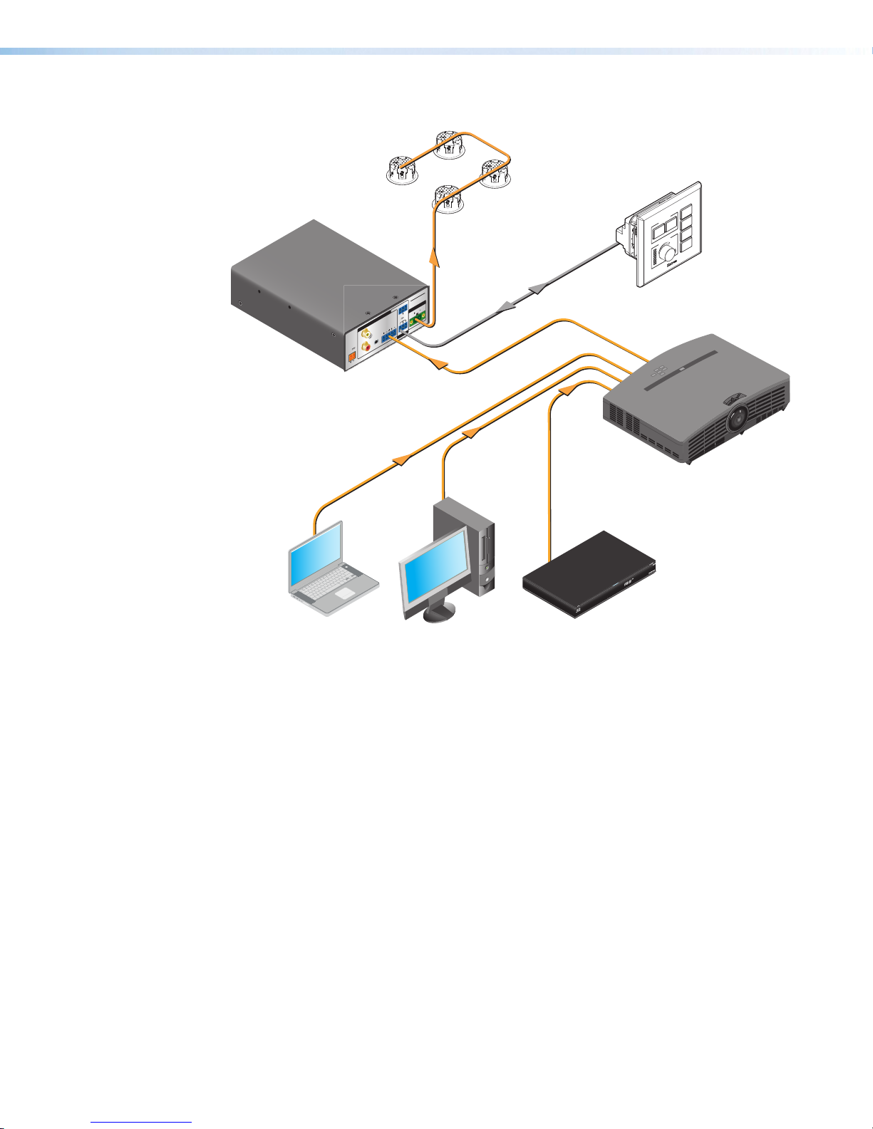
Application Diagram
INPUTS
L
(SUMMED)
POWER
12V
R
1.3A MAX
Extron
MPA 601
Mini Power
Amplier
Extron
SF 3CT LP
Full-Range
Ceiling Speakers
DISPLAY
ON OFF
VOLUME
PC
VGA
DOC
CAM
MUTE
Extron
MPA 601-70V
G
TIMER OFF
70V OUTPUT
STANDBY
50mA
R
10V
R
CLASS 2 WIRING
(SUMMED)
L
G
C
V
REMOTE
MLC Plus 100
Controller
Projector
Laptop Room PC Blu-ray Disc
Figure 1. MPA 601 Application Diagram
MPA 601 • Introduction 4
Page 11

Installation
This section provides a description of the MPA 601-70V and MPA 601-100V rear panel
connections and instructions for cabling.
Rear Panel Connections
F
E
F
E
STANDBY
10V
R
V
C
REMOTE
G
50mA
G
MPA 601-70V
70V OUTPUT
CLASS 2 WIRING
INPUTS
L
(SUMMED)
POWER
12V
1.3A MAX
R
A B D HG
Timer Off Pin Connector
E
Standby Pin Connector
F
Remote Input Connector
G
Speaker Output Connection
H
C
L
(SUMMED)
TIMER OFF
R
STANDBY
10V
R
V
C
REMOTE
G
50mA
G
INPUTS
L
(SUMMED)
POWER
12V
1.3A MAX
R
A B D HG
Power Connector
A
RCA Audio Input Connectors
B
3.5 mm TRS Input Connector
C
Balanced or Unbalanced Audio
D
C
L
(SUMMED)
TIMER OFF
R
Input Connector
Figure 2. MPA 601-70V and MPA 601-100V Rear Panel Connections
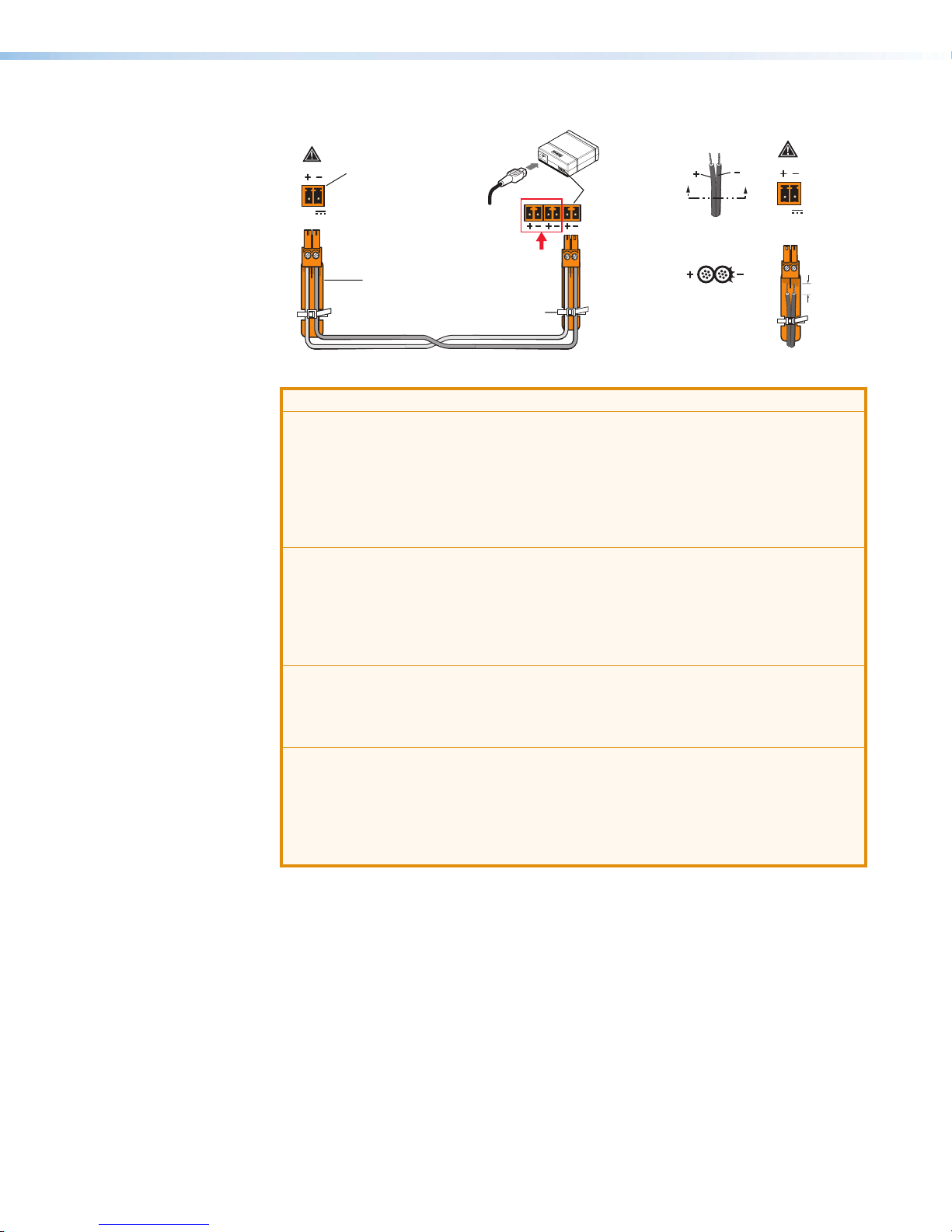
Power Connector — A 36W desktop power supply is provided. Connect one end
A
of the DC power cord to one of the 2-pole 3.5 mm captive screw outlets on the
power supply. Connect the other end into the power connector on the rear panel of
the amplifier as shown above. The power cord connectors are correctly wired when
shipped (see figure 3 on the next page for instructions on connecting the power
supply).
ATTENTION:
• When the PS 1230 power supply is connected to the MPA 601, it must not be
shared with any other device.
• Lorsque la source d’alimentation PS 1230 est connectée au MPA 601, elle ne
peut être utilisée pour alimenter un autre appareil.
MPA 601-100V
100V OUTPUT
CLASS 2 WIRING
MPA 601 • Installation 5
Page 12
MPA 601 serie
Amplifier
Output Cord
PS 1230 Power Supply
(5 mm) Max.
MPA 601 series
POWER
12V
1.5 A MAX
s
Power Receptacle
DC Power Cord
Captive Screw Connector
AC Power Cord
DO NOT USE
Wrap
Tie
DC Power
Outputs
Captive Screw
Connector
Power Supply
Smooth
Power Supply
Output Cord
SECTION A–A
Amplifier
POWER
Ridges
AA
12V
1.5 A MAX
3/16"
Figure 3. Connecting the PS 1230 Power Supply to the MPA 601 Amplifier
ATTENTION:
• Always use a power supply provided by or specified by Extron. Use of an
unauthorized power supply voids all regulatory compliance certification and
may cause damage to the supply and the end product.
• Utilisez toujours une source d’alimentation fournie ou recommandée par
Extron. L’utilisation d’une source d’alimentation non autorisée annule toute
conformité réglementaire et peut endommager la source d’alimentation ainsi
que le produit final.
• Suitable for use in environmental air space in accordance with Section
300.22.C of the National Electrical Code, and Sections 2-128, 12 010(3) and
12-100 of the Canadian Electrical Code, Part 1, C22.1.
• Convient à une utilisation dans les conduits d’aération, en accord avec la
section 300.22.C du code national d’électricité américain, et avec les sections
2-128, 12-010(3) et 12-100 du code d’électricité canadien, partie 1, C22.1.
• Unless otherwise stated, the AC/DC adapters are not suitable for use in air
handling spaces or in wall cavities.
• Sauf mention contraire, les adaptateurs AC/DC ne sont pas appropriés pour
une utilisation dans les espaces d’aération ou dans les cavités murales.
• The installation must always be in accordance with the applicable provisions of
National Electrical Code ANSI/NFPA 70, article 725 and the Canadian Electrical
Code part 1, section 16.
• Cette installation doit toujours être en accord avec les mesures qui s’applique
au National Electrical Code ANSI/NFPA70, article725, et au Canadian
Electrical Code, partie1, section16.
MPA 601 • Installation 6
Page 13
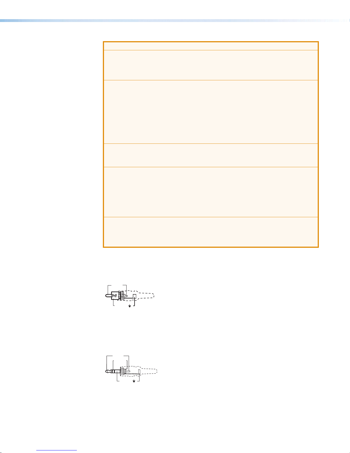
ATTENTION:
Tip (+)
Sleeve ( )
RCA Connector
Sleeve ( )
Ring (R)
Tip (L)
3.5 mm TRS Connector
• The power supply shall not be permanently fixed to building structure or similar
structure.
• La source d’alimentation ne devra pas être fixée de façon permanente à une
structure de bâtiment ou à une structure similaire.
• Although the amplifier is plenum rated, the power supply provided with it is not.
Cables to and from the amplifier must also be plenum rated. The power supply
must not be placed in the plenum space. The DC power cord provided with the
unit is not plenum rated.
• Bien que l’amplificateur soit conforme à la norme relative aux faux plafonds,
la source d’alimentation fournie avec ne l’est pas. Les câbles depuis et vers
l’amplificateur doivent aussi être classés plenum. La source d’alimentation ne
doit pas être placée dans l’espace plenum. Le cordon d’alimentation DC fourni
avec l’unité n’est pas classé plenum.
• The length of the exposed wires in the stripping process is critical.
• La longueur des câbles exposés est primordiale lorsque l’on entreprend de
les dénuder.
• The ideal length is 3/16 inches (5 mm). Any longer and the exposed wires may
touch, causing a short circuit between them. Any shorter and the wires can be
easily pulled out even if tightly fastened by the captive screws.
• La longueur idéale est de 5mm (3/16inches). S’ils sont un peu plus longs, les
câbles exposés pourraient se toucher et provoquer un court circuit. S’ils sont
un peu plus courts, ils pourraient sortir, même s’ils sont attachés par les vis
captives.
• Do not tin the wires. Tinned wires are not as secure in the captive screw
terminals and could pull out.
• Ne pas étamer les câbles. Les câbles étamés ne sont pas aussi bien fixés dans
les terminaisons des à vis captives et pourraient sortir.
RCA Audio Input Connectors — These connectors accept unbalanced, line level
B
audio signal. The input can be stereo, using two RCA connectors, or mono, using a
single RCA connector plugged into the left (summed) connector.
If unused, the connectors automatically terminate to lower the noise floor.
Figure 4. RCA Wiring Example
3.5 mm TRS Input Connector — This connector accepts unbalanced, line level audio
C
signal through a 3.5 mm tip ring sleeve (TRS) connector.
If unused, the connector automatically terminates to lower the noise floor.
Figure 5. 3.5 mm TRS Wiring Example
MPA 601 • Installation 7
Page 14

Balanced Stereo Input
Unbalanced Stereo Input
Tip
Slee
Slee
LR
MPA 601-70V
70V OUTPUT
10V
50mA
Tip
Balanced or Unbalanced Audio Input Connector — This 5-pole 3.5 mm captive
D
screw connector accepts line level, balanced or unbalanced, mono or stereo audio
signal. Figure 6 below shows connector wiring for the appropriate input type.
Ring
Sleeves
Ring
Tip
Tip
LR
Sleeve
Tip
LR
ve
ve
LR
Sleeve
Tip
Ring
Unbalanced Mono Input
Balanced Mono Input
Figure 6. Audio Input Connector Wiring Example
ATTENTION:
• The length of the exposed wires in the stripping process is critical. The ideal
length is 3/16 inch (5 mm). If the exposed portion is longer, the wires may
touch, causing a short circuit between them. If the exposed wires are shorter,
they can be easily pulled out, even if tightly fastened by the captive screws.
• La longueur des câbles exposés est primordiale lorsque l’on entreprend de
les dénuder. La longueur idéale est de 5mm (3/16inches). S’ils sont un peu
plus longs, les câbles exposés pourraient se toucher et provoquer un court
circuit. S’ils sont un peu plus courts, ils pourraient sortir, même s’ils sont
attachés par les vis captives.
• Do not tin the wires. Tinned wire does not hold its shape and can become
loose over time.
• Ne pas étamer les câbles. Les câbles étamés ne sont pas aussi bien fixés
dans les terminaisons des à vis captives et pourraient sortir.
Timer Off Pin Connector —When the TIMER OFF pin is shorted to ground, the
E
STANDBY timer is disabled and the amplifier does not automatically go into Standby
mode after 25 minutes (±5 minutes). The MPA 601 can still be forced into standby
mode using the STANDBY pin, even if the timer has been defeated.
Standby Pin Connector — When the STANDBY pin is shorted to ground, it forces the
F
MPA 601 to go into standby mode. The front panel power LED turns amber to indicate
when the MPA 601 is in standby.
When the short is removed from the STANDBY pin, the unit may remain in standby
mode, depending on certain conditions:
• The STANDBY timer is enabled.
• The input signal is below the signal input detection threshold.
• The timeout interval since the last detection of a signal has elapsed.
NOTE: If the TIMER OFF pin is shorted to ground, the unit will always come out of
standby when the short is removed from the STANDBY pin.
TIMER OFF
Figure 7. Standby Port Connector
G
STANDBY
MPA 601 • Installation 8
Page 15

Remote Input Connector —This 3-pole captive screw connector allows a
CLASS 2 WIRING
MPA 601-70V
70V OUTPUT
STANDBY
G
CLASS 2 WIRING
70V OUTPUT
CLASS 2 WIRING
100V OUTPUT
e
L
Captiv
3.5 mm
G
wall-mounted audio controller to control volume and mute remotely (for more
information on operating a remote controller see Remote Control Operation on
page 11).
10V
50mA
R
V
C
G
REMOTE
Figure 8. Remote Input Connector
Speaker Output Connector — This 2-pole 5 mm screw-lock captive screw connector
H
is used to connect speakers to the amplifier. The MPA 601-70V provides up to 60W
for a 70V distributed sound system, while the MPA 601-100V provides up to 60W for a
100V distributed sound system.
Figure 9. MPA Speaker Output Connector
ATTENTION:
• Do not ground or short the speaker outputs as this will damage the amplifier.
• Ne pas mettre à la terre ni créer de court-circuit dans les sorties de l’enceinte,
afin d’éviter tout risque de détérioration de l’amplificateur.
The MPA 601 amplifiers sum the left and right signals from both the TRS and RCA
inputs to form Sum 1 (see figure 10 below). Sum 1 is then weighted. At the same time,
the amplifier sums the left and right signals from the captive screw input to form Sum 2.
Sum 1 and Sum 2 are then summed together to form a single mono signal.
NOTE: All inputs are buffered.
RCA
R
+
Sum 1
+
L
TRS
R
+
+
Sum 2
Screw
+
L
-
e
+
R
-
Figure 10. MPA 601 Signal Summing Diagram
+
+
Amp Stag
MPA 601 • Installation 9
Page 16

Operation
This section provides information about the front panel features and operation of the
MPA601 and covers the following topics:
• Front Panel Features
• Setting Input Level
• Setting Bass and Treble
• Remote Control Operation
• Troubleshooting
Front Panel Features
A
B C D
BASSLEVEL TREBLE
MPA 601
MINI POWER AMPLIFIER
Power LED
A
Output Level Potentiometer
B
Bass Potentiometer
C
Treble Potentiometer
D
Figure 11. MPA 601-70V and MPA 601-100V Front Panel
NOTE: The front panels of the MPA 601-70V and MPA 601-100V are identical.
Power LED — Lights green when the unit is fully on and amber when the unit is in
A
Output Level Potentiometer — Adjusts the amount of attenuation applied to the input
B
Bass Potentiometer — Adjusts the amount of attenuation or gain applied to the bass
C
Treble Potentiometer — Adjusts the amount of attenuation or gain applied to the
D
Setting Input Level
To adjust the attenuation of the input signal:
1. If necessary, unplug the remote connector from the unit.
2. If connecting the amplifier to a system with adjustable volume, use a flat head
3. Set the system volume to its maximum level. No sound should come out.
4. Slowly increase the amplifier LEVEL until sound distortion starts to occur (rotate
standby mode.
signal.
frequencies of the input signal (±10 dB ≤ 100 Hz).
treble frequencies of the input signal (±10 dB ≥ 10 kHz).
screwdriver (such as the provided Extron Tweeker) to adjust the LEVEL potentiometer to
its minimum setting (fully counterclockwise).
potentiometer clockwise). Lower the LEVEL slightly until the distortion disappears. This
setting ensures that whatever the system volume setting may be, no clipping occurs.
MPA 601 • Operation 10
Page 17

Setting Bass and Treble
V
10K Ohms
R
NOTES:
• When the potentiometer is at the center detent (vertical), the frequency response is
flat. Turning the BASS or TREBLE potentiometers counterclockwise will decrease the
output level at the specified frequencies, while turning the potentiometers clockwise
will increase the level at the specified frequencies.
• Increasing the bass or treble levels after the input level has been set may result in
clipping.
• Exercise caution when adjusting the bass. It is possible to saturate the transformer
cores of high impedance speakers if the bass is set incorrectly.
To adjust the bass and treble:
1. Using a small flat head screwdriver (such as the provided Extron Tweeker), adjust the
BASS potentiometer to increase or decrease the bass shelving ±10 dB at 100 Hz and
below.
2. Using a small flat head screwdriver (such as the provided Extron Tweeker), adjust the
TREBLE potentiometer to increase or decrease the treble shelving ±10 dB at 10 kHz and
above.
Remote Control Operation
Options for remote control include the Extron VC 50, VCM 100 AAP, VCM 100 MAAP,
VCM200 series, MLA VC10 Plus, MLC 55 RS VC, and MLC 64 RS VC D. For information
on these devices, including part numbers, go to www.extron.com. Third party 10k
potentiometer volume controllers can also be used for remote volume and mute control.
See figure 12 and the bullets below for wiring the VCM 100 MAAP. Wiring for the other
Extron remote control units is similar.
olume Pot
REMOTE
10 V (Pin 1)
2K
Mute
Switch
V
C
Vol/Mute
(Pin 2)
GND (Pin 3)
G
Figure 12. Remote Control Wiring
• Pin 1 is 10 VDC reference voltage.
• Pin 2 (Vol/Mute) can be used as a variable voltage input between 0 and 10 VDC with
0V providing full attenuation and 10V providing no attenuation. It can also be used for
remote control muting. Sound is muted while the pin is shorted to ground.
• Pin 3 is ground.
NOTE: All nominal levels are ±10%.
MPA 601 • Operation 11
Page 18

Controlling Multiple Amplifiers with One Remote Controller
Extron
Several MPA 601 units can be daisy-chained so that one volume controller can
simultaneously regulate the volume of all the amplifiers.
NOTES:
• As additional amplifiers are added to the daisy chain, the sensitivity of the remote
control volume potentiometer will change. The maximum level (fully clockwise)
will not be affected. However, the effectiveness of the minimum level (fully
counterclockwise) in reducing the volume to inaudible levels decreases as more
amplifiers are added to the daisy chain.
• When more than two MPA units are attached to the chain, sound may begin to be
heard even if the levels have been set to their lowest. Muting the output can be
achieved with a contact closure button attached between the Vol/Mute and Ground
pin of the first MPA in the chain.
To regulate multiple amplifiers with a single remote controller:
1. Attach all three pins of the volume controller to the corresponding pins on the first
MPA601 unit (ground to ground, Vol/Mute to Vol/Mute, and 10V to 10V).
2. Use jumper wires to connect the Vol/Mute pins of the first amplifier to the Vol/Mute pins
of each successive amplifier.
3. Use jumper wires to connect the Ground pins of the first amplifier to the Ground pins of
each successive amplifier.
Extron
VCM 100 AAP
VOL/MUTE
10V
MPA 601
daisy chain
10V 50mA
VCG
REMOTE
10V 50mA
VCG
REMOTE
10V 50mA
VCG
REMOTE
Figure 13. Regulating Multiple Amps with a Single Remote Wiring Example
NOTE: The 10V pin of the remote controller connects to the first MPA 601 only.
There are no jumper wires linking it to subsequent amplifiers.
MPA 601 • Operation 12
Page 19
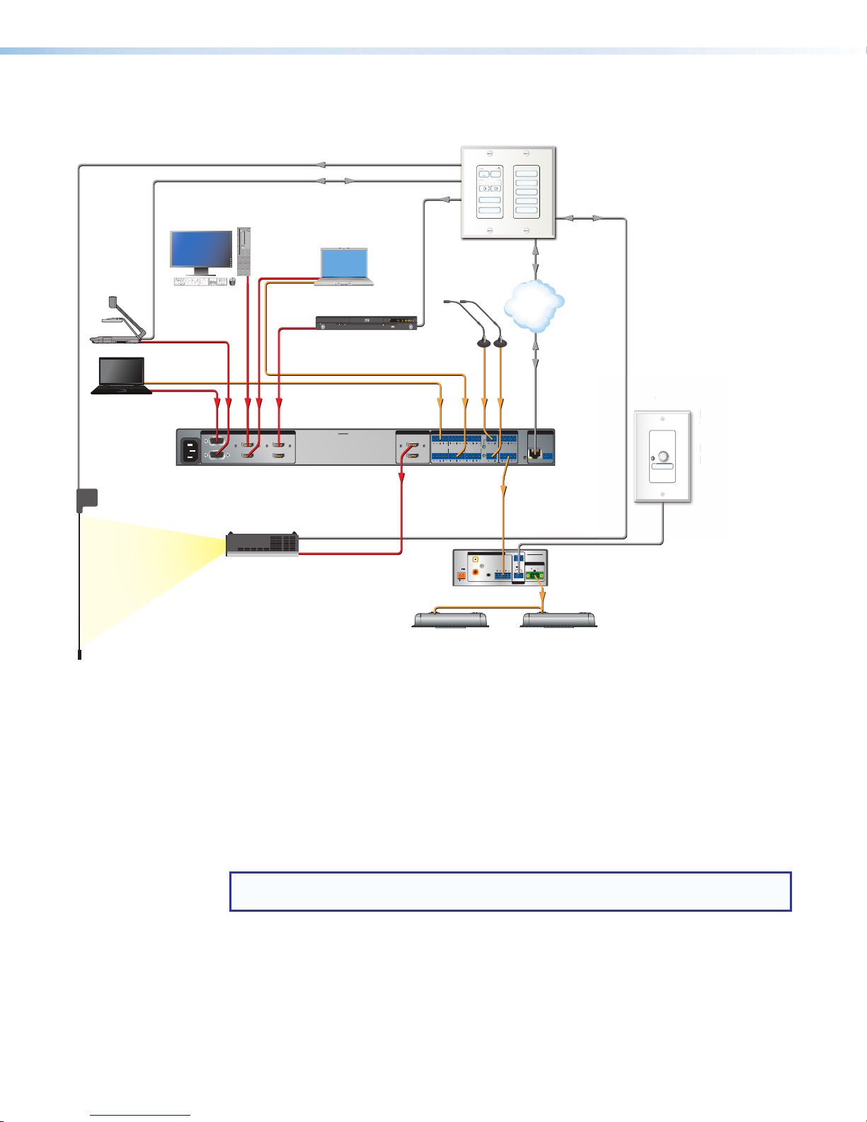
Control Options
e
E
o
V
V
m
M
D
r
Document
Camera
Laptop
Extron
IN1606
Scaling
Presentation
Switcher
Screen Control
esc
F1 F2 F3F4 F5 F6 F7 F8 F9 F10 F11 F12 F13 F14 F15 F16 F17 F18F19
_
!1@2#3$4%5^6&7*8(9)
+
~
-
delete
0
=
`
|\}]{
QWERTYUIOP
[
tab
“‘:
ASDFGHJ
KL
;
caps lock
return
caps lock
<,>.?
ZXCVBNM
/
shift
shift
alt
control
optioncommand
commandoption control
PC
HDMI with
Embedded
Audio
VGA
Audio
VGA
100-240V ~ 50/60 Hz
-- A MAX
1
2
Relay
RS-232
IR
WiFi
1234
Laptop
DisplayPort
to HDMI
page
fnhome clear
page
enddelete
down
CONFIGURABLE
up
7
4
1
Adapter
=/
*
-
9
8
+
6
5
3
2
0.
enter
Audio
HDMI with
Embedded
Audio
Blu-ray Player
STANDBY/ON
PQLS HDMIOPEN/CLOSEFL OFF
USB
Microphones
1 and 2
Audio
INPUTS OUTPUTS AUDIO INPUTSOUTPUTSREMOTE
5
3
HDMI
HDMI
6
4
IN1606
A
L1
L3
L5
R
HDMI
B
R
L2
L4
L6
R
R
ON
AUTO IMAGE
A/V MUTE
R
+48V
R
+48V
DISPLAY
VOLUME
Extron
MIC/LINE
2
OFF
1
2
PC
LAPTOP
DOC CAM
HDMI
VGA
TCP/IP
Network
Audio
12
VARIABLE
LR
RESET
Audio
Extron
MLC Plus 84 D
MediaLink Plus
Controller
Decora Wallplate
RS-232
Ethernet/PoE
Ethernet
LAN
RS-232
Tx Rx
G
1
1
VOLUME
MUTE
Extron
xtr
VCM 200 D
CM
Volume and
olu
Mute Controller
ute
Decora® Wallplat
eco
MPA 601-70V
TIMER OFF
G
Extron
STANDBY
70V OUTPUT
10V
50mA
L
R
(SUMMED)
R
MPA 601-70V
V
C
G
CLASS 2 WIRING
REMOTE
Mini Power Amplier
Projector
HDMI
INPUTS
L
(SUMMED)
POWER
12V
1.3A MAX
R
Audio
Extron
CS 1226T
SpeedMount Ceiling Speaker System
Figure 14. Direct and Indirect Remote Control Options
Direct Remote Control — For a system designed to control the volume of the
1
amplifier directly, use a 10k Ohm potentiometer to control volume via the rear panel
remote port on the MPA 601 (see figure 2 G on page 5). In figure 14 above, a
VCM200D adjusts the level on the MPA 601 directly. Follow instructions found in the
control product user guide.
Indirect Remote Control — For a system with variable audio output, connect the
2
audio source output to the input of the MPA 601. In figure 14 above, an MLCPlus 84D
adjusts the audio level on the audio source via a network connection. Follow the
instructions in the control product user guide.
NOTE: The diagram above is for illustrative purposes only. Only one type of remote
control (direct or indirect) should be used to control the volume in any given system.
MPA 601 • Operation 13
Page 20

Troubleshooting
Amplifier Fails to Exit Standby Mode Promptly
Under different circumstances, the front panel LED lights green or amber, which provides
diagnostic information.
Power LED
Color
Amber No output signal. • No input detected: verify that there is an
Green or
Amber
Amber DC Fault is detected on
Problem Description Problem Solution
input signal. If a signal is present, raise the
input level.
• The amplifier is in standby mode and the
output has been turned off. Check the
remote port.
Slow to exit standby
mode when a signal is
present.
either channel. The unit
does not exit standby.
• The input signal may be too weak. Raise
the input level.
• DC Fault may have been detected.
Disconnect power then disconnect the
remote port (if connected). Next, reconnect
power to the unit to determine if the unit
immediately goes into standby upon power
up. In such a case, the unit should be
serviced.
Amplifier Enters Standby Mode Too Early
Power LED
Color
Green or
Amber
Problem Description Problem Solution
Enters standby mode
early.
• The input signal may be too weak. Raise
the input level.
MPA 601 • Operation 14
Page 21

Mounting
This section provides information about the various ways to mount the MPA601 and covers
the following topics:
• Plenum Placement
• Tabletop Placement
• Rack Mounting
• Under-Desk, Through-Desk, and Projector Mounting
Plenum Placement
The MPA 601-70V and MPA 601-100V amplifiers are plenum rated for heat and smoke
release. They can be installed in the ceiling, out of sight, with reduced risk of theft.
ATTENTION:
• Although the amplifier is plenum rated, the power supply provided with it is not.
• Bien que l’amplificateur soit conforme à la norme relative aux faux plafonds,
Cables to and from the amplifier must also be plenum rated. The power supply
must not be placed in the plenum space. The DC power cord provided with the unit
is not plenum rated.
la source d’alimentation fournie avec ne l’est pas. Les câbles depuis et vers
l’amplificateur doivent aussi être classés plenum. La source d’alimentation ne doit
pas être placée dans l’espace plenum. Le cordon d’alimentation DC fourni avec
l’unité n’est pas classé plenum.
Tabletop Placement
Attach the four provided rubber feet to the bottom of the unit and place it on a convenient
tabletop location.
MPA 601 • Mounting 15
Page 22
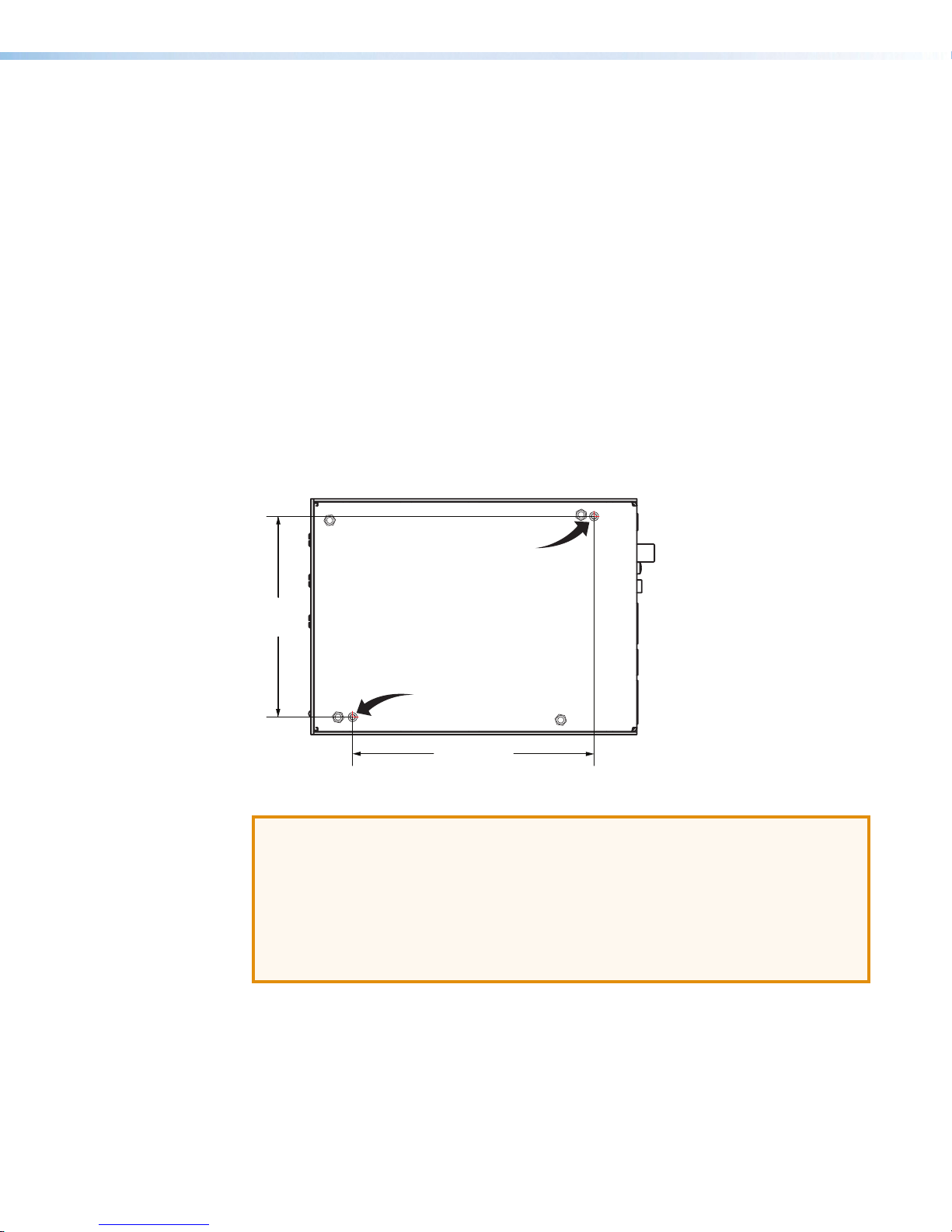
Rack Mounting
(9.39 cm)
The following Underwriters Laboratories (UL) guidelines are relevant to the safe installation of
these products in a rack:
• Elevated operating ambient temperature — If the equipment is installed in a
closed or multi-unit rack assembly, the operating ambient temperature of the rack
may be greater than room ambient temperature. Therefore, install the equipment in an
environment compatible with the maximum ambient temperature specified by Extron
(TMA = +122°F, +50°C).
• Reduced air flow — Install the equipment in the rack so that the amount of air flow
required for safe operation of the equipment is not compromised.
• Mechanical loading — Mount the equipment in the rack so that uneven mechanical
loading does not create a hazardous condition.
• Circuit overloading — When connecting the equipment to the supply circuit, consider
the effect that circuit overloading might have on overcurrent protection and supply
wiring. Consider equipment nameplate ratings when addressing this concern.
• Reliable earthing (grounding) — Maintain reliable grounding of rack-mounted
equipment. Pay particular attention to supply connections other than direct connections
to the branch circuit (such as the use of power strips).
#4-40 Thread Thru
Rack Mounting
3.70"
#4-40 Thread Thru
Rack Mounting
4.44"
(11.29 cm)
Figure 15. Points for Securing the Base of the MPA 601 to a Rack
ATTENTION:
• Use only the two holes indicated in the diagram above for mounting the MPA 601.
The other four holes anchor stand-offs for the internal circuit boards. Using them
may damage the amplifier and will not provide secure mounting for the unit.
• Utilisez uniquement les deux trous indiqués dans le schéma ci-dessus pour monter
le MPA 601. Les quatre autres trous fixent des entretoises pour les circuits imprimés
internes. Leur utilisation pourrait endommager l’amplificateur et n’offira ainsi aucune
solution de montage sécurisé de l’unité.
Under-Desk, Through-Desk, and Projector Mounting
The MPA 601 can be mounted under a desk, through a desk, or above a projector. For the
appropriate mounting kit, go to www.extron.com. Follow the instructions provided with
each kit.
MPA 601 • Mounting 16
Page 23

Extron Warranty
Extron Electronics warrants this product against defects in materials and workmanship for a period of three years
from the date of purchase. In the event of malfunction during the warranty period attributable directly to faulty
workmanship and/or materials, Extron Electronics will, at its option, repair or replace said products or components,
to whatever extent it shall deem necessary to restore said product to proper operating condition, provided that it is
returned within the warranty period, with proof of purchase and description of malfunction to:
USA, Canada, South America,
and Central America:
Extron Electronics
1230 South Lewis Street
Anaheim, CA 92805
U.S.A.
Europe and Africa:
Extron Europe
Hanzeboulevard 10
3825 PH Amersfoort
The Netherlands
Japan:
Extron Electronics, Japan
Kyodo Building, 16 Ichibancho
Chiyoda-ku, Tokyo 102-0082
Japan
China:
Extron China
686 Ronghua Road
Songjiang District
Shanghai 201611
China
Asia:
Extron Asia Pte Ltd
135 Joo Seng Road, #04-01
PM Industrial Bldg.
Singapore 368363
Middle East:
Extron Middle East
Dubai Airport Free Zone
F13, PO Box 293666
United Arab Emirates, Dubai
Singapore
This Limited Warranty does not apply if the fault has been caused by misuse, improper handling care, electrical
or mechanical abuse, abnormal operating conditions, or if modifications were made to the product that were not
authorized by Extron.
NOTE: If a product is defective, please call Extron and ask for an Application Engineer to receive an RA (Return
Authorization) number. This will begin the repair process.
USA: 714.491.1500 or 800.633.9876 Europe: 31.33.453.4040
Asia: 65.6383.4400 Japan: 81.3.3511.7655
Units must be returned insured, with shipping charges prepaid. If not insured, you assume the risk of loss or damage
during shipment. Returned units must include the serial number and a description of the problem, as well as the
name of the person to contact in case there are any questions.
Extron Electronics makes no further warranties either expressed or implied with respect to the product and its quality,
performance, merchantability, or fitness for any particular use. In no event will Extron Electronics be liable for direct,
indirect, or consequential damages resulting from any defect in this product even if Extron Electronics has been
advised of such damage.
Please note that laws vary from state to state and country to country, and that some provisions of this warranty may
not apply to you.
Extron Headquarters
+1.800.633.9876 (Inside USA/Canada Only)
Extron USA - West Extron USA - East
+1.714.491.1500 +1.919.850.1000
+1.714.491.1517 FAX +1.919.850.1001 FAX
Extron Europe
+800.3987.6673
(Inside Europe Only)
+31.33.453.4040
+31.33.453.4050 FAX
© 2017 Extron Electronics All rights reserved. www.extron.com
Extron Asia
+65.6383.4400
+65.6383.4664 FAX
Extron Japan
+81.3.3511.7655
+81.3.3511.7656 FAX
Extron China
+86.21.3760.1568
+86.21.3760.1566 FAX
Extron Middle East
+971.4.299.1800
+971.4.299.1880 FAX
Extron Australia
+61.8.8113.6800
+61.8.8351.2511 FAX
Extron India
1800.3070.3777
(Inside India Only)
+91.80.3055.3777
+91.80.3055.3737 FAX
 Loading...