

Page 1

MP 101 Series
Microphone to Line Preamplifiers
User Guide
Category
68-992-02 Rev. B
04 19
Page 2

Safety Instructions
Safety Instructions • English
WARNING: This symbol, , when used on the product, is intended to
alert the user of the presence of uninsulated dangerous voltage within the
product’s enclosure that may present a risk of electric shock.
ATTENTION: This symbol, , when used on the product, is intended
to alert the user of important operating and maintenance (servicing)
instructions in the literature provided with the equipment.
For information on safety guidelines, regulatory compliances, EMI/EMF
compatibility, accessibility, and related topics, see the Extron Safety and
Regulatory Compliance Guide, part number 68-290-01, on the Extron
website, www.extron.com.
Sicherheitsanweisungen • Deutsch
WARNUNG: Dieses Symbol auf dem Produkt soll den Benutzer darauf
aufmerksam machen, dass im Inneren des Gehäuses dieses Produktes
gefährliche Spannungen herrschen, die nicht isoliert sind und die einen
elektrischen Schlag verursachen können.
VORSICHT: Dieses Symbol auf dem Produkt soll dem Benutzer in
der im Lieferumfang enthaltenen Dokumentation besonders wichtige
Hinweise zur Bedienung und Wartung (Instandhaltung) geben.
Weitere Informationen über die Sicherheitsrichtlinien, Produkthandhabung,
EMI/EMF-Kompatibilität, Zugänglichkeit und verwandte Themen finden Sie in
den Extron-Richtlinien für Sicherheit und Handhabung (Artikelnummer
68-290-01) auf der Extron-Website, www.extron.com.
Instrucciones de seguridad • Español
ADVERTENCIA: Este símbolo, , cuando se utiliza en el producto,
avisa al usuario de la presencia de voltaje peligroso sin aislar dentro del
producto, lo que puede representar un riesgo de descarga eléctrica.
ATENCIÓN: Este símbolo, , cuando se utiliza en el producto, avisa
al usuario de la presencia de importantes instrucciones de uso y
mantenimiento recogidas en la documentación proporcionada con el
equipo.
Para obtener información sobre directrices de seguridad, cumplimiento
de normativas, compatibilidad electromagnética, accesibilidad y temas
relacionados, consulte la Guía de cumplimiento de normativas y seguridad
de Extron, referencia 68-290-01, en el sitio Web de Extron, www.extron.com.
Instructions de sécurité • Français
AVERTISSEMENT : Ce pictogramme, , lorsqu’il est utilisé sur le
produit, signale à l’utilisateur la présence à l’intérieur du boîtier du
produit d’une tension électrique dangereuse susceptible de provoquer
un choc électrique.
ATTENTION : Ce pictogramme, , lorsqu’il est utilisé sur le produit,
signale à l’utilisateur des instructions d’utilisation ou de maintenance
importantes qui se trouvent dans la documentation fournie avec le
matériel.
Pour en savoir plus sur les règles de sécurité, la conformité à la
réglementation, la compatibilité EMI/EMF, l’accessibilité, et autres sujets
connexes, lisez les informations de sécurité et de conformité Extron, réf.
68-290-01, sur le site Extron, www.extron.com.
Istruzioni di sicurezza • Italiano
AVVERTENZA: Il simbolo, , se usato sul prodotto, serve ad
avvertire l’utente della presenza di tensione non isolata pericolosa
all’interno del contenitore del prodotto che può costituire un rischio di
scosse elettriche.
ATTENTZIONE: Il simbolo, , se usato sul prodotto, serve ad avvertire
l’utente della presenza di importanti istruzioni di funzionamento e
manutenzione nella documentazione fornita con l’apparecchio.
Per informazioni su parametri di sicurezza, conformità alle normative,
compatibilità EMI/EMF, accessibilità e argomenti simili, fare riferimento
alla Guida alla conformità normativa e di sicurezza di Extron, cod. articolo
68-290-01, sul sito web di Extron, www.extron.com.
Instrukcje bezpieczeństwa • Polska
OSTRZEŻENIE: Ten symbol, , gdy używany na produkt, ma na celu
poinformować użytkownika o obecności izolowanego i niebezpiecznego
napięcia wewnątrz obudowy produktu, który może stanowić zagrożenie
porażenia prądem elektrycznym.
UWAGI: Ten symbol, , gdy używany na produkt, jest przeznaczony do
ostrzegania użytkownika ważne operacyjne oraz instrukcje konserwacji
(obsługi) w literaturze, wyposażone w sprzęt.
Informacji na temat wytycznych w sprawie bezpieczeństwa, regulacji
wzajemnej zgodności, zgodność EMI/EMF, dostępności i Tematy pokrewne,
zobacz Extron bezpieczeństwa i regulacyjnego zgodności przewodnik, część
numer 68-290-01, na stronie internetowej Extron, www.extron.com.
安全说明 • 简体中文
警告: 产品上的这个标志意在警告用户该产品机壳内有暴露的危险 电压,
有触电危险。
注意: 产品上的这个标志意在提示用户设备随附的用户手册中有
重要的操作和维护(维修)说明。
关于我们产品的安全指南、遵循的规范、EMI/EMF 的兼容性、无障碍
使用的特性等相关内容,敬请访问 Extron 网站 , www.extron.com,参见
Extron 安全规范指南,产品编号 68-290-01。
Page 3

安全記事 • 繁體中文
警告: 若產品上使用此符 號,是為了提醒使用者,產品機殼內存在著
可能會導致觸電之風險的未絕緣危險電壓。
注意 若產品上使用此符號,是為了提醒使用者,設備隨附的用戶手冊中有
重 要 的 操 作 和 維 護( 維 修 )説 明 。
有關安全性指導方針、法規遵守、EMI/EMF 相容性、存取範圍和相關主題的詳細資
訊,請瀏覽 Extron 網站:www.extron.com,然後參閱《Extron 安全性與法規
遵守手冊》,準則編號 68-290-01。
安全上のご注意 • 日本語
警告: この記 号 が製品上に表示されている場合は、筐体内に絶縁されて
いない高電圧が流れ、感電の危険があることを示しています。
注意:この記号 が製品上に表示されている場合は、本機の取扱説明書に
記載されている重要な操作と保守( 整備)の 指示についてユーザーの注 意
を喚起するものです。
安全上のご注意、法規厳守、EMI/EMF適合性、その他の関連項目に
つ い て は 、エ ク ストロ ン の ウ ェ ブ サ イト www.extron.com よ り 『 Extron Safety
and Regulatory Compliance Guide』 ( P/N 68-290-01) をご覧ください。
안전 지침 • 한국어
경고: 이 기호 가 제품에 사용될 경우, 제품의 인클로저 내에 있는
접지되지 않은 위험한 전류로 인해 사용자가 감전될 위험이 있음을
경고합니다.
주의: 이 기호 가 제품에 사용될 경우, 장비와 함께 제공된 책자에 나와
있는 주요 운영 및 유지보수(정비) 지침을 경고합니다.
안전 가이드라인, 규제 준수, EMI/EMF 호환성, 접근성, 그리고 관련 항목에
대한 자세한 내용은 Extron 웹 사이트(www.extron.com)의 Extron 안전 및
규제 준수 안내서, 68-290-01 조항을 참조하십시오.
Copyright
© 20xx-2019 Extron Electronics. All rights reserved. www.extron.com
Trademarks
All trademarks mentioned in this guide are the properties of their respective owners.
The following registered trademarks (®), registered service marks (SM), and trademarks (TM) are the property of RGBSystems, Inc. or
ExtronElectronics (see the current list of trademarks on the Terms of Use page at www.extron.com):
Registered Trademarks (
®
)
Extron, Cable Cubby, ControlScript, CrossPoint, DTP, eBUS, EDID Manager, EDID Minder, Flat Field, FlexOS, Glitch Free. Global
Configurator, GlobalScripter, GlobalViewer, Hideaway, HyperLane, IPIntercom, IPLink, KeyMinder, LinkLicense, LockIt, MediaLink,
MediaPort, NetPA, PlenumVault, PoleVault, PowerCage, PURE3, Quantum, Show Me, SoundField, SpeedMount, SpeedSwitch,
StudioStation, SystemINTEGRATOR, TeamWork, TouchLink, V-Lock, VideoLounge, VN-Matrix, VoiceLift, WallVault, WindoWall, XTP,
XTPSystems, and ZipClip
Registered Service Mark
(SM)
: S3 Service Support Solutions
Trademarks (™
)
AAP, AFL (Accu-RateFrameLock), ADSP(Advanced Digital Sync Processing), Auto-Image, AVEdge, CableCover, CDRS(ClassD
Ripple Suppression), Codec Connect, DDSP(Digital Display Sync Processing), DMI (DynamicMotionInterpolation), DriverConfigurator,
DSPConfigurator, DSVP(Digital Sync Validation Processing), eLink, EQIP, Everlast, FastBite, FOX, FOXBOX, IP Intercom HelpDesk,
MAAP, MicroDigital, Opti-Torque, PendantConnect, ProDSP, QS-FPC(QuickSwitch Front Panel Controller), RoomAgent, Scope-Trigger,
ShareLink, SIS, SimpleInstructionSet, Skew-Free, SpeedNav, Triple-Action Switching, True4K, Vector™ 4K , WebShare, XTRA, and
ZipCaddy
Page 4

FCC Class A Notice
This equipment has been tested and found to comply with the limits for a Class A digital
device, pursuant to part15 of the FCC rules. The ClassA limits provide reasonable
protection against harmful interference when the equipment is operated in a commercial
environment. This equipment generates, uses, and can radiate radio frequency energy and,
if not installed and used in accordance with the instruction manual, may cause harmful
interference to radio communications. Operation of this equipment in a residential area is
likely to cause interference. This interference must be corrected at the expense of the user.
NOTES:
VCCI-A Notice
この装置は、クラスA情報技術装置です。 この装置を家庭環境で使用すると、電波妨害を引き
起こすことがあります。 その場合には使用者が適切な対策を講ずるよう要求されることがあります。
VCCI -A
• (if only this paragraph is used, reformat to single NOTE format.) For
more information on safety guidelines, regulatory compliances, EMI/EMF
compatibility, accessibility, and related topics, see the Extron Safety and
Regulatory Compliance Guide on the Extron website.
Conventions Used in this Guide
Notifications
The following notifications are used in this guide:
ATTENTION:
• Risk of property damage.
• Risque de dommages matériels.
NOTE: A note draws attention to important information.
TIP: A tip provides a suggestion to make working with the application easier.
Specifications Availability
Product specifications are available on the Extron website, www.extron.com.
Extron Glossary of Terms
A glossary of terms is available at http://www.extron.com/technology/glossary.
aspx.
Page 5

Contents
Introduction ................................................1
About this Manual................................................ 1
About the MP 101, MP 101 AAP, and
MP 101 D ........................................................... 1
Features .............................................................. 1
MP 101 Series Rear Panels .......................... 2
Rear Panel Features ............................................ 2
Power Connector ............................................ 2
Remote Connection ......................................... 4
Mic Input (Microphone Level) ........................... 4
Audio Output (Line Level) ................................. 5
Low Cut Filter Switch ....................................... 5
Phantom Power ............................................... 5
MP 101 .......................................................6
Front Panel Features ............................................ 6
Mounting the MP 101 .......................................... 6
Adjusting the MP 101 .......................................... 7
Remote Control ................................................... 7
Remote Connector Wiring ............................... 7
Remote Control Options .................................. 7
MP 101 D ..................................................12
Front Panel Features .......................................... 12
Adjusting the MP 101 D ..................................... 12
Mounting the MP 101 D .................................... 13
Remote Control ................................................. 14
Remote Connector Wiring ............................. 14
Remote Control Options ................................ 14
Architectural Installation ............................15
Installation Instructions ...................................... 15
Preparing the Site and Installing the Wall Box .... 15
Dimensions and Template for the
MP101D ..................................................18
Dimensions........................................................ 18
Template............................................................ 19
MP 101 AAP ................................................ 8
Front Panel Features ............................................ 8
Adjusting the MP 101 AAP .................................. 9
Mounting the MP 101 AAP .............................. 9
Remote Control ................................................. 10
Remote Connector Wiring ............................. 10
Remote Control Options ................................ 11
vTechnical Publications Standards and Styles • Contents
Page 6

Technical Publications Standards and Styles • Contents vi
Page 7

Introduction
About this Manual
This manual contains information about the MP 101, the MP 101 AAP, and the MP 101 D
microphone to line preamplifiers and provides instructions on how to mount and operate
these units.
About the MP 101, MP 101 AAP, and MP 101 D
The Extron MP 101, MP 101 AAP, and MP 101 D (the MP 101 Series) are high quality
microphone to line level audio preamplifiers. These products can add microphone capability
to most Extron audio and switcher systems.
The MP 101 is rack-mountable, while the MP 101 AAP is an AAP plate option for easy
integration into Extron architectural products. The MP 101 D works similarly to the other two
units, but features a Decorator-style wallplate mounting option. Information on its installation
and operation are found in MP 101 D starting on page12.
Each model features a recessed Mic Gain potentiometer that provides a 25 to 72 dB
adjustment range, compensating for different microphone sensitivities. Each model also
features an on/off switch for 48 volt phantom power and low cut filtering. Remote control is
available through optional Extron VCM 110 AAP panel, which control volume and muting.
Features
• Compact size — The MP 101 is housed in a 1U high, 1/8 rack width, 3” deep, metal
enclosure, the MP 101 AAP is housed in a two-space AAP plate; and the MP 101 D is
mounted into a wallplate. These three options allow for diverse applications.
• Quick plug input and outputs — Connectors are captive screw or XLR (MP 101 AAP
and MP 101 D only) for quick installation.
• Gain control — Provides a wide gain adjustment range of 25 to 72 dB.
• Switchable low cut filter — Provides low cut filter to remove wind and “table rumble”
noise.
• Switchable phantom power — Provides 48 volt phantom power for condenser
microphones.
• Volume and mute remote control — Each model can be remotely controlled for
volume adjustment and muting via a rear panel Remote connector.
• Flexible mounting options — The MP 101 can be mounted on a rack, on a table, or
under furniture. The MP 101 AAP mounts into various Extron architectural products.
The MP 101 D is wall mountable using standard, off-the-shelf mounting accessories.
• External international power supply — The autoswitchable, 12 VDC, 0.5 A external
power supply provides worldwide power compatibility.
MP 101 Series • Introduction 1
Page 8

MP 101 Series Rear
43
Rear Panel
)
Connector
3/16" (5 mm) MAX
Smooth
Panels
This section covers rear panel feature for the MP 101, the MP 101 APP, and the MP101D.
Rear Panel Features
5
5
MP 101
MIC TO LINE
PREAMPLIFIER
POWER
12V
0.3A MAX
INPUT
LINE
OUTPUT
MIC
REMOTE
10V
VOL/MUTE
11224
MP 101 MP 101 AAP MP 101 D
Power Connector 5 Audio Output (Line Level) (MP 101 only)
1
Power LED (MP 101 only) 6 Low Cut Filter Switch (MP 101 APP and MP 101 D)
2
Remote Connection 7 Phantom Power (MP 101 APP and MP 101 D)
3
Mic Input
4
Figure 1. MP 101, MP 101 APP, and MP 101 D Rear Panel
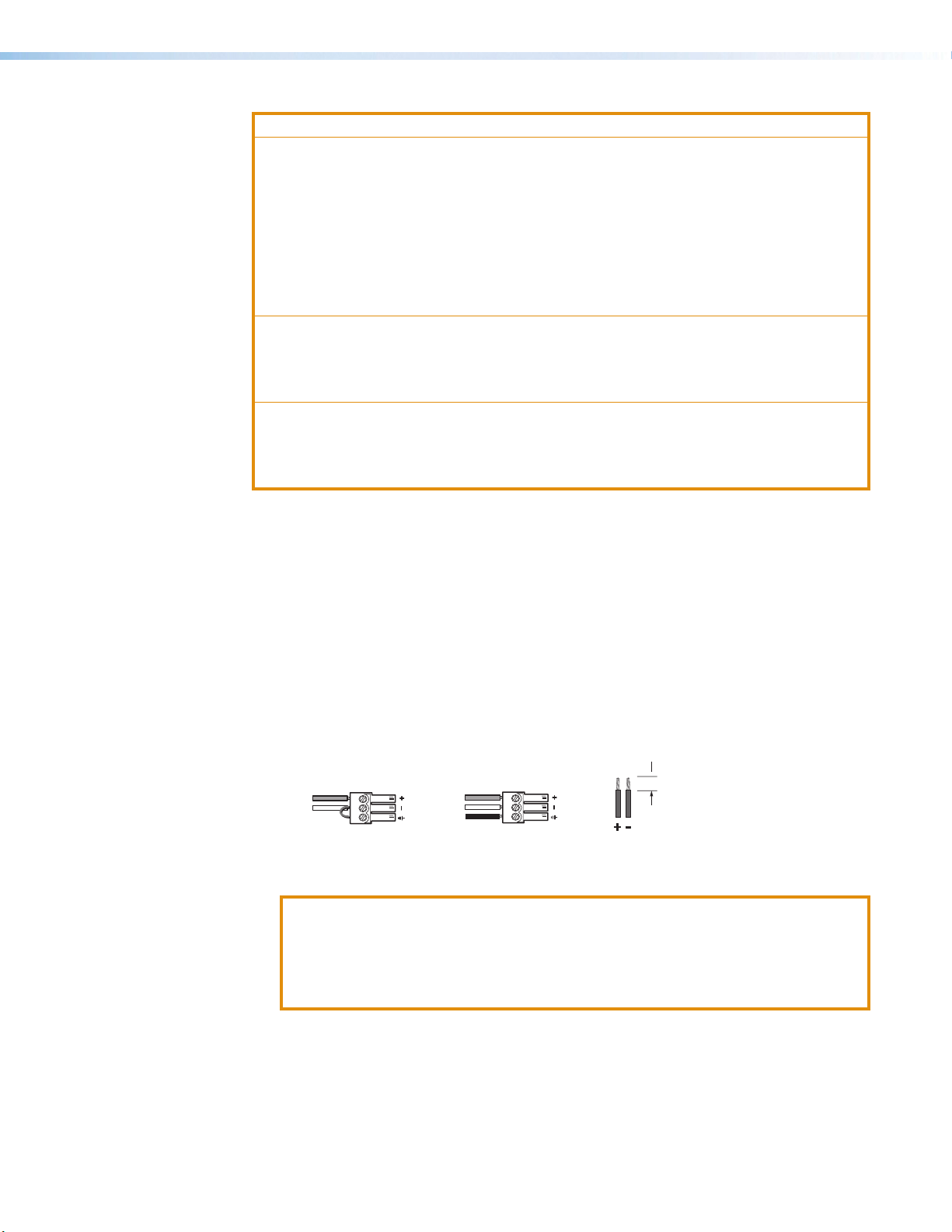
Power Connector
Power connector — An external 12 V power supply is included with the unit. Plug it
1
into this 2-pole captive screw connector. Wire the connector as shown below.
Power Receptacle
DC Power Cord
Captive Screw
Connector
Ground
Ridged
– Return
+12 VDC input
all devices.
Smooth
3
External
Power Supply
(12 VDC, 0.5 A max.
Ridges
A A
SECTION A–A
Power Supply
Output Cord
Captive Screw
To verify the polarity before connection, plug in the power supply
with no load and check the output with a voltmeter.
Figure 2. Rear Panel 12 VDC Power Connector
MP 101 Series • MP 101 Series Rear Panels 2
Page 9

ATTENTION:
• The DC output cables must be kept separate from each other while the power
supply is plugged in. Remove power before wiring
• Les câbles de sortie CC doivent être séparés les uns des autres tant que la
source d’alimentation est branchée. Coupez l’alimentation avant d’effectuer les
raccordements.
• Do not connect power to the amplifier until you have read the ATTENTION
notifications.
• Ne branchez pas l’alimentation au l’amplificateur avant d’avoir lu les mises en garde
« ATTENTION ».
• Always use a power supply supplied or specified by Extron. Use of an unauthorized
power supply voids all regulatory compliance certification and may cause damage
to the supply and the end product.
• Utilisez toujours une source d’alimentation fournie ou recommandée par Extron.
L’utilisation d’une source d’alimentation non autorisée annule toute certification de
conformité réglementaire et peut endommager la source d’alimentation et l’unité.
• If not provided with a power supply, this product is intended to be supplied by a
power source marked “Class 2” or “LPS” and rated at 12VDC and a minimum of
0.5A.
• Si le produit n’est pas fourni avec une source d’alimentation, il doit être alimenté par
une source d’alimentation de classe 2 ou LPS, avec une tension nominale 12 Vcc,
0,5 A minimum.
• The installation must always be in accordance with the applicable provisions of
National Electrical Code ANSI/NFPA 70, article 725 and the Canadian Electrical
Code part 1, section 16. The power supply shall not be permanently fixed to
building structure or similar structure.
• Cette installation doit toujours être conforme aux dispositions applicables du Code
américain de l’électricité (National Electrical Code) ANSI/NFPA 70, article 725, et
du Code canadien de l’électricité, partie1, section16. La source d’alimentation ne
devra pas être fixée de façon permanente à une structure de bâtiment ou à une
structure similaire.
• Power supply voltage polarity is critical. Incorrect voltage polarity can damage the
power supply and the unit. The ridges on the side of the cord (see figure2 on the
previous page) identify the power cord negative lead.
• La polarité de la source d’alimentation est primordiale. Une polarité incorrecte
pourrait endommager la source d’alimentation et l’unité. Les stries sur le côté
du cordon (voir figure2) permettent de repérer le pôle négatif du cordon
d’alimentation.
• To verify the polarity before connection, plug in the power supply with no load and
check the output with a voltmeter.
• Pour vérifier la polarité avant la connexion, brancher l’alimentation hors charge et
mesurer sa sortie avec un voltmètre.
MP 101 Series • MP 101 Series Rear Panels 3
Page 10
ATTENTION:
Slee
(high impedance)
• The length of the exposed (stripped) wires is important. The ideal length is
3/16inch (5mm). Any longer and the exposed wires may touch, causing a short
circuit between them. Any shorter and the wires can be easily pulled out even if
tightly fastened by the captive screws.
• La longueur des câbles exposés est primordiale lorsque l’on entreprend de les
dénuder. La longueur idéale est de 5mm (3/16inches). S’ils sont trop longs, les
câbles exposés pourraient se toucher et provoquer un court circuit. S’ils sont trop
courts, ils peuvent être tirés facilement, même s’ils sont correctement serrés par les
borniers à vis.
• Unless otherwise stated, the AC/DC adapters are not suitable for use in air handling
spaces or in wall cavities.
• Sauf mention contraire, les adaptateurs CA/CC ne conviennent pas à une utilisation
dans les espaces d’aération ou dans les cavités murales.
• Remote power is intended for indoors use only. No part of a network that uses
remote power can be routed outdoors.
• L’alimentation à distance est exclusivement réservée à un usage en intérieur. Un
réseau utilisant une alimentation à distance ne peut pas être routé en extérieur.
Power LED (MP 101 only) (see figure1 on page2) — This LED lights green to
2
indicate that the unit is receiving power.
Remote Connection
Remote — An optional 3-pin, captive screw connector allows a wall mounted audio
3
controller or MediaLink product to remotely control volume and mute levels for the
MP101 unit (see Remote Control on page7).
Mic Input (Microphone Level)
Mic Input (MP 101 only) — A 3-pin, captive screw connector for a standard
4
condenser microphone connection.
Tip
ve
Unbalanced Input
(high impedance)
Figure 3. Audio Wiring Input
ATTENTION:
• For unbalanced audio, ensure that the Phantom power switch is set to the OFF
position.
• Pour l’audio asymétrique, assurez-vous que le switch d’alimentation fantôme
est inactif.
Tip
Ring
Sleeve
Balanced Input
3/16"
(5 mm) MAX
Captive Screw
Connector stripping
MP 101 Series • MP 101 Series Rear Panels 4
Page 11

Audio Output (Line Level)
(high impedance)
Slee
Line Output — A 3-pin, captive screw connector outputs to audio mixers, amps
5
switchers, or other non-microphone audio equipment.
3/16"
(5 mm) MAX
Captive Screw
Connector stripping
Tip
Ring
ve
Balanced Output
Figure 4. Audio Wiring Output
ATTENTION:
• For unbalanced audio, connect the sleeve(s) to the ground. DO NOT connect
the sleeves to the negative (-) contact.
• Pour l’audio asymétrique, connectez les manchons au contact au sol. Ne PAS
connecter les manchons aux contacts négatifs (–).
Low Cut Filter Switch
CAUTION
For unbalanced audio, connect the sleeve(s)
to the ground. DO NOT connect the sleeve(s)
to the negative (-) contact.
Tip
NO Ground Here
Sleeve
Unbalanced Output
Low Cut filter switch (MP 101 AAP and MP 101 D) — Provides low cut filtering to
6
remove wind and “table rumble” noise.
Phantom Power
Phantom Power (MP 101 AAP and MP 101 D) — Provides switchable 48 volt
7
phantom power for condenser microphone.
MP 101 Series • MP 101 Series Rear Panels 5
Page 12

MP 101
11223344
The Extron MP 101 is a high performance, microphone to line level audio preamplifier.
Topics covered in the section are:
• Front Panel Features • Adjusting the MP 101
• Mounting the MP 101
Front Panel Features
Figure 5. Front Panel
MIC GAIN
(dB)
25 72
LOW CUT PHANTOM
ON
OFF
MP 101
Power LED — This LED lights green to indicate
1
that the unit is receiving power.
Mic Gain — A recessed, adjustable
2
potentiometer defines the amount of input
signal (between 25 and 72 dB) allowed into the
preamp.
Low Cut filter switch — Provides switchable
3
low cut filtering to remove wind and “table
rumble” noise.
Phantom power switch — Provides
4
switchable 48 volt phantom power for condenser
microphone
Mounting the MP 101
There are many optional accessories for mounting the MP 101 (see accessories on
the MP101 page of the Extron website). The following Underwriters Laboratories (UL)
guidelines pertain to the safe installation of the MP 101 in a rack.
UL Rack Mounting Guidelines
1. Elevated operating ambient temperature — If installed in a closed or multi-unit rack
assembly, the operating ambient temperature of the rack environment can be greater
than room ambient temperature. Therefore, install the unit in an environment compatible
with the maximum ambient temperature (Tma = +122°F, +50°C) specified by Extron.
2. Reduced air flow — Install the equipment in a rack so that the amount of air flow
required for safe operation of the equipment is not compromised.
3. Mechanical loading — Mount the equipment in the rack so that a hazardous
condition is not achieved due to uneven mechanical loading.
4. Circuit overloading — Connect the equipment to the supply circuit and consider the
effect that circuit overloading might have on overcurrent protection and supply wiring.
Appropriate consideration of equipment nameplate ratings should be used when
addressing this concern.
5. Reliable earthing (grounding) — Maintain reliable grounding of rack-mounted
equipment. Pay particular attention to supply connections other than direct connections
to the branch circuit (for example: use of power strips).
MP 101 Series • MP 101 6
Page 13

Adjusting the MP 101
REMOTE
10K
MAX
MI
After the MP 101 has been properly mounted and connected, do the following to adjust it:
1. If using a condenser microphone, set the Phantom power switch to the ON position.
If using a dynamic microphone, set the Phantom power switch to the OFF position.
2. When using the microphone for voice audio, flip the Low Cut switch to ON to reduce
wind and “table rumble” noise.
When using the microphone for music audio, flip the Low Cut switch to OFF to
preserve the optimum sound quality.
3. Set the Mic Gain potentiometer by saying a few words into the microphone and
adjusting for the maximum sound level that is free of distortion.
NOTE: If there is a remote control connection, unplug it while adjusting the Mic Gain
If there is minimal distortion, but greater volume is required, turn the Mic Gain potentiometer
clockwise (towards the 75 dB mark) to increase the volume, but not past the point where
distortion occurs.
Remote Control
The wiring and control options described below pertain to all models in the MP 101 series.
potentiometer. Replace the remote control when finished.
Remote Connector Wiring
As shown below, Pin 1 is 10 VDC reference voltage. Pin 2 is volume control DC voltage;
range is 0 to 10 V, where 0 V is mute and 10 V provides maximum volume. Pin 3 is ground.
NOTE: All nominal levels are at ±10%.
123
10V
VOL/MUTE
2K
N
MUTE
Figure 6. Remote Connector Wiring
Remote Control Options
The MP 101 has three remote control options:
1. The Extron VCM 110 AAP volume/mute controller, VCM 200 Series volume/mute
controller, VC 50 volume controller, MLC 55 RS VC, and MLC 64 RS VC D use a 10 k
ohm potentiometer as the main method for controlling volume levels.
2. The Extron MLA-VC10 Plus converts RS-232 serial command to 0 to 10 V variable DC
for volume control.
3. Generic volume/mute controllers are standard 10 k ohm potentiometers.
1
2
3
GND
MP 101
MIC TO LINE
PREAMPLIFIER
POWER
12V
0.3A MAX
MIC
INPUT
LINE
OUTPUT
REMOTE
10V
VOL/MUTE
MP 101 Series • MP 101 7
Page 14

MP 101 AAP
The Extron MP 101 AAP is a high performance microphone to line level audio preamplifier.
This model is a two-space MP 101 AAP in black. Topics covered in this section are:
• Front Panel Features • Mounting the MP 101
• Adjusting the MP 101 AAP • Remote Control
Front Panel Features
3
3
112
Figure 7. Front Panel MP 101 APP
XLR mic input — Use an XLR connector or a
1
standard microphone connection (see the image on
the right for connector pin out information).
Mic Gain — A recessed, adjustable potentiometer
2
defines the amount of input signal (between 25 and
72 dB) allowed into the preamp.
This potentiometer is covered by a plastic cap to avoid tampering. To adjust the
potentiometer, use a small screwdriver to remove the covering, make adjustments, then
replace the cap.
Active and Mute LEDs — The active LED lights green to indicate active sound. The
3
mute LED lights red to indicate mute.
Mute button — Toggles between active sound and mute (indicated by its LEDs).
4
When used with an optional Extron VCM 110 AAP controller, the two controllers are
synchronized.
24
4
2
3
3-pin
Female
1
MP 101 Series • MP 101 APP 8
Page 15

Adjusting the MP 101 AAP
Most adjustment options for the MP 101 AAP are located on its rear panel (see MP 101
Series Rear Panels on page2). Therefore, you must perform these adjustments prior
to final mounting into a wall or a piece of furniture.
To adjust the MP 101 AAP, do the following:
1. If using a condenser microphone, flip the Phantom power switch to the ON position.
If using a dynamic microphone, flip the Phantom power switch to the OFF position.
2. When using the microphone for voice audio, flip the Low Cut switch to ON to reduce
wind and “table rumble” noise.
When using the microphone for music audio, flip the Low Cut switch to OFF to
preserve the optimum sound quality.
3. Set the Mic Gain potentiometer by saying a few words into the microphone and
adjusting for the maximum sound level that is free of distortion.
NOTE: If there is a remote control connection, unplug it while adjusting the Mic
Gain potentiometer. Replace the remote control when finished.
4. If there is minimal distortion, but greater volume is required, turn the Mic Gain
potentiometer clockwise (towards the 75 dB mark) to increase the volume, but not past
the point where distortion occurs.
Mounting the MP 101 AAP
The MP 101 AAP must be attached to a device faceplate or AAP wallplate and then cabled
before you can test and perform the final mount (installation into a wall or piece of furniture).
NOTE: Before mounting, the MP 101 AAP should be tested to verify that its
connections and settings are correct.
To mount the MP 101 AAP into a device faceplate or AAP wallplate, do the following:
1. Before any cables are attached, insert the MP 101 AAP standoffs through the holes in
the device faceplate or AAP wallplate.
2. Secure all cables and connections into the rear connectors of the MP 101 AAP.
3. Using the provided #4-40 nuts and captive washers, secure the preamplifier to the
faceplate or wallplate, as shown below.
MP 101 Series • MP 101 APP 9
Page 16
Wall Stud
REMOTE
GND
MA
Screws or Nails
Cable
Clamp
Extron
#4-40 Nut w/ Captive
Washer
AAP 102
ACTIVE
MUTE
MIC
IN
MLP 101 AAP
AAP 102
Extron
Installation Cable
MP 101 AAP
MIC to Line
Preamplifier
Figure 8. Mounting the MP 101 APP
4. Repeat steps 1 through 3 to mount any other AAPs. Cover any openings in the
faceplate with blank plates (provided).
5. If it was not done previously, adjust the MP 101 AAP from its rear panel (see Adjusting
the MP 101 AAP on the previous page for detailed instructions).
6. Pretest the MP 101 AAP before final mounting of the faceplate.
7. Perform the final mount by attaching the cabled device faceplate or AAP wallplate into
a wall or piece of furniture. For detailed installation information, refer to the installation
guide shipped with the faceplate.
Remote Control
The wiring and control options described below pertain to all models in the MP 101 series.
Remote Connector Wiring
Pin 1 is 10 VDC reference voltage. Pin 2 is volume control
DC voltage; range is 0 to 10 V, where 0 V is mute and 10 V
provides maximum volume. Pin 3 is ground.
NOTE: All nominal levels are at ±10%.
X
10K
MIN
123
10V
VOL/MUTE
2K
MUTE
1
2
3
MP 101 Series • MP 101 APP 10
Page 17

Remote Control Options
The MP 101 AAP has three remote control options:
1. The Extron VCM 110 AAP volume/mute controller, VCM 200 Series volume/mute
controller, VC 50 volume controller, MLC 55 RS VC, and MLC 64 RS VC D and VC 50
volume controller use a 10 k ohm potentiometer as the main method for controlling
volume levels.
The VCM 110 AAP mute button overrides the mute button of the MP 101 D.
2. The Extron MLA-VC10 Plus converts RS-232 serial command to 0 to 10 volt variable
DC for volume control.
3. Generic volume/mute controllers are standard 10 k ohm potentiometers.
MP 101 Series • MP 101 APP 11
Page 18

MP 101 D
The Extron MP 101 D provides the same features as the other MP 101 models in a
convenient, Decorator-style wallplate. Like the MP 101 and MP 101 AAP, this mic to line
preamplifier can be remotely controlled via a VCM volume/mute control module.
Topics covered in this section are:
• Front Panel Features • Mounting the MP 101 D
• Remote Control
Front Panel Features
1
1
3
3
ACTIVE
MIC IN
MUTE
22
4
4
Active LED — This LED lights green to indicate that
1
the unit is receiving power.
Mute LED — This LED lights red to indicate mute.
2
Mic Gain — A recessed, adjustable potentiometer
3
defines the amount of input signal (between 25 and
72dB) allowed into the preamp.
This potentiometer is covered by a plastic cap to
avoid tampering. To adjust the potentiometer, use
a small screwdriver to remove the covering, make
adjustments, then replace the cap.
XLR mic input — An XLR connector for a standard
4
microphone connection.
Figure 9. Front Panel MP 101 D
Adjusting the MP 101 D
Adjustment options for the MP 101 D are located on its rear panel (see Front Panel
Features). Therefore, you must perform these adjustments before mounting into a wall.
To adjust the MP 101 D, do the following:
1. If using a condenser microphone, set the Phantom power switch to the ON position.
If using a dynamic microphone, set the Phantom power switch to the OFF position.
2. When using the microphone for voice audio, flip the Low Cut switch to ON to reduce
wind and “table rumble” noise.
When using the microphone for music audio, set the Low Cut switch to OFF to
preserve the optimum sound quality.
2
3
3-pin
Female
1
MP 101 Series • MP 101 D 12
Page 19

3. Set the Mic Gain potentiometer by saying a few words into the microphone and
W
adjusting for the maximum sound level that is free of distortion.
NOTE: If there is a remote control connection, unplug it while adjusting the Mic
Gain potentiometer. Replace the remote control when finished.
If there is minimal distortion, but greater volume is required, turn the Mic Gain
potentiometer clockwise (towards the 75 dB mark) to increase the volume, but not past
the point where distortion occurs.
Mounting the MP 101 D
The MP 101 D provides the same features as the other MP 101 models in a convenient,
Decorator-style wallplate.
NOTE: Before mounting, the MP 101 D should be tested to verify that its connections
and settings are correct.
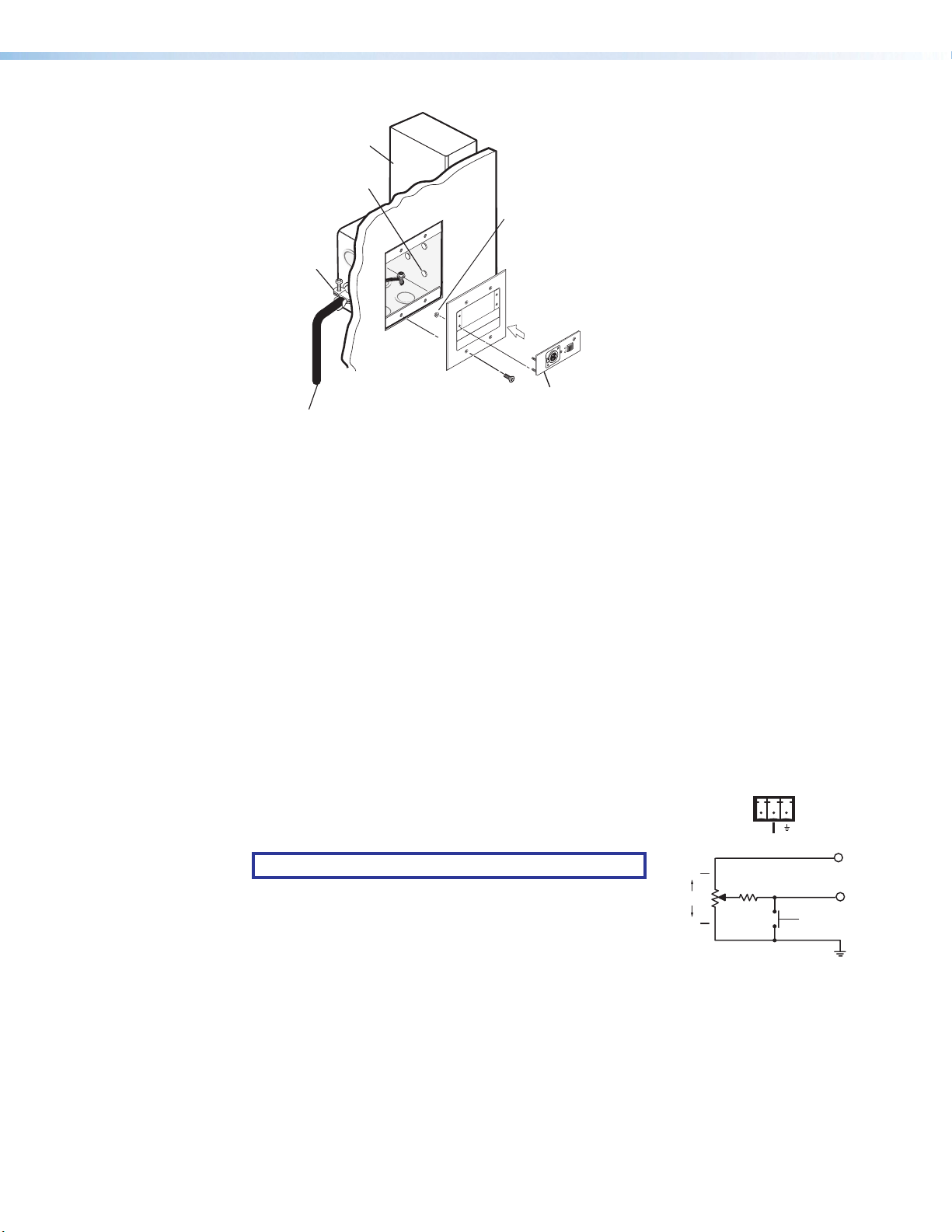
To mount the MP 101 D into a Decorator-style faceplate, do the following:
1. Secure all cables and connections onto the MP 101 D.
2. If it was not done previously, adjust the MP 101 D from its rear panel (see Adjusting
the MP 101 D on the previous page for detailed instructions).
3. Place the MP 101 D through the opening in the wall or furniture and into the wall box.
Take care not to damage the output cables, which fit behind the preamplifier at the back
of the wall box.
4. Attach the Decorator-style wallplate to the MP 101 D, as shown below.
Wall Box
MUTE
all opening
is flush with
edge of box.
Extron
MP 101 D
Mic to Line
Preamplifier
Figure 10. Mounting the MP 101 D
5. Pretest the MP 101 D before performing the final mount in step 6.
6. Perform the final mount by attaching the cabled MP 101 D and Decorator-style
faceplate into a wall. For detailed installation information, refer to the installation guide
shipped with the Decorator-style faceplate.
ACTIVE
MIC IN
Decorator Style
Faceplate
MP 101 Series • MP 101 D 13
Page 20

Remote Control
REMOTE
MA
MIN
Remote Connector Wiring
Pin 1 is 10 VDC reference voltage. Pin 2 is volume control
DC voltage; range is 0 to 10 V, where 0 V is mute and
10 V provides maximum volume. Pin 3 is ground.
NOTE: All nominal levels are at ±10%.
Remote Control Options
The MP 101 D has three remote control options:
1. The Extron VCM 110 AAP volume/mute controller, VCM 200 Series volume/mute
controller, VC 50 volume controller, MLC 55 RS VC, and MLC 64 RS VC D and VC
50 volume controller use a 10 k ohm potentiometer as the main method for controlling
volume levels.
The VCM 110 AAP mute button overrides the mute button of the MP 101 AAP.
2. The Extron MLA-VC10 Plus converts RS-232 serial command to 0 to 10 volt variable
DC for volume control.
3. Generic volume/mute controllers are standard 10 k ohm potentiometers.
10K
123
10V
VOL/MUTE
X
2K
MUTE
1
2
3
GND
MP 101 Series • MP 101 D 14
Page 21

Architectural Installation
Topics covered in this section are:
• Installation Instructions
• Preparing the Site and Installing the Wall Box
Installation Instructions
Two versions of the MP 101 series, the MP 101 AAP and MP 101 D, can be mounted into
furniture, a wall, or a floor box. Unless otherwise noted, both units (the MP 101 AAP and the
MP 101 D) are referred to as the “MP 101” in the following instructions.
ATTENTION:
• The MP 101 must be installed into an Underwriters Laboratories (UL) approved
electrical wall box. The box is not included with the MP 101; the installer is
responsible for obtaining and installing the box.
• Le MP 101 doit être installé dans un boîtier mural électrique homologué UL
(Underwriters Laboratories). Le boîtier n’est pas fourni avec le MP 101 ; il incombe à
l’installeur d’obtenir et d’installer le boîtier.
Preparing the Site and Installing the Wall Box
Choose a location that allows cable runs without interference. Allow enough depth for both
the wall box and the cables.
You may need to install the cables into the wall, furniture, or conduits before installing the
mic driver.
• The MP 101 AAP can be installed into an HSA 400 Series surface access enclosure,
or into a two-gang or four-gang wall box. Its faceplate accepts up to four single height
Extron Architectural Adapter Plates (AAPs).
• The MP 101 D can be installed into a standard or compact one-gang electrical wall box
using the included Decorator-style wallplate.
The installation must conform to national and local electrical codes and to the MP 101
size requirements. Dimensional drawings and a template for the MP 101 D are provided in
appendix B of this manual.
1. For the MP 101 D only, see the Template on page19. A template is not required for
the MP101AAP.
NOTE: The template is not shown at full size. Pay attention to the measurements
shown on the template.
MP 101 Series • Architectural Installation 15
Page 22

2. Mark the guidelines for the opening on the wall or furniture.
Connecting Shields.eps
Foil Shield
• If the MP 101 will be installed in a wall box, place the box against the installation
surface and draw a line on it around the outside of the box.
• If the MP 101 will be installed without a wall box (using mud rings or fastening it
directly to the wall or furniture), measure and mark the surface for the cutout area
indicated in the template.
3. Cut out the material from the marked area.
4. Check the opening size by inserting the wall box (if used) or the MP 101 (if no box is
used) into the opening. The box and preamplifier should fit easily into the opening.
Enlarge or smooth the edges of the opening if needed.
5. Feed cables through the wall box punch-out holes, and secure them with cable clamps
to provide strain relief.
6. Exposed cable shields (braids or foil) are potential sources of short circuits. Trim back
and/or insulate shields with heat shrink.
Metal Wall Box
Cable Clamp
Install Cable
Screw
Braided Shield
Figure 11.
ATTENTION:
• To prevent short circuits, cut back the outer foil shield to the point where the
cable exits the cable clamp.
• Afin d’éviter les courts-circuits, réduisez le blindage en aluminium extérieur
jusqu’à ce que le câble sorte de la cosse de câble.
• Both braided and foil shields should be connected to an equipment ground at
the other end of the cable, as shown above.
• Les blindages tressés et en aluminium devraient être connectés à la masse d’un
équipement à l’autre bout du câble, comme illustré ci-dessus.
MP 101 Series • Architectural Installation 16
Page 23

7. Insert the wall box into the opening, and attach it to the wall, stud, or furniture.
Installation Cab
• If the MP 101 AAP or MP 101 D are being installed in a two- or four-gang AAP
plate, attach the wall box to the wall stud or furniture with nails or screws, leaving
the front edge flush with the outer wall or furniture surface. See the illustration
below, which applies to one-, two-, three-, and four-gang wall boxes.
Wall Stud
le
Cable Clamp
Installation Cable
Screws or NailsScrews or Nails
Wall Stud
Cable Clamp
Figure 12. Installing the Wall Box
• If attaching the wall box to wood, use four #8 or #10 screws or 10-penny nails. A
minimum of 1/2 inch (1.3 cm) of screw threads must penetrate the wood.
• If attaching the wall box to metal studs or furniture, use four #8 or #10 self-tapping
sheet metal screws or machine bolts with matching nuts.
MP 101 Series • Architectural Installation 17
Page 24

Dimensions and
(4.3 mm)
)
Template for the
MP101D
Dimensions
NOTE: Always check and use the dimensions in this appendix.
1.29"
(32.8 mm)
0.17"
0.33"
(8.4 mm)
0.13"
(3.3 mm)
0.1"
(2.5 mm)
2.6"
(66 mm)
1.29"
(33 mm)
Figure 13. MP 101 D Dimensions
4.10"
(104 mm
0.33"
(8.4 mm)
MP 101 Series • Dimensions and Template for the MP 101 D 18
Page 25

Template
(114.3 mm)
the Electrical
Cut-Out Template for the Extron
NOTE: This template is not to scale.
MP 101 D
2.79"
(70.9 mm)
2.24"
(105 cm)
Top Panel
SURFACE
4.50"
4.13"
(57 cm)
CUT-OUT
AREA FOR
MOUNTING
Location of
MP 101 D
Circuit Board
Cut Out Line
for Installing
Box
Figure 14. Template for MP 101 D
MP 101 Series • Dimensions and Template for the MP 101 D 19
Page 26

Extron Warranty
Extron Electronics warrants this product against defects in materials and workmanship for a period of three years
from the date of purchase. In the event of malfunction during the warranty period attributable directly to faulty
workmanship and/or materials, Extron Electronics will, at its option, repair or replace said products or components,
to whatever extent it shall deem necessary to restore said product to proper operating condition, provided that it is
returned within the warranty period, with proof of purchase and description of malfunction to:
USA, Canada, South America,
and Central America:
Extron Electronics
1230 South Lewis Street
Anaheim, CA 92805
U.S.A.
Europe and Africa:
Extron Europe
Hanzeboulevard 10
3825 PH Amersfoort
The Netherlands
Asia:
Extron Asia Pte Ltd
135 Joo Seng Road, #04-01
PM Industrial Bldg.
Singapore 368363
Singapore
This Limited Warranty does not apply if the fault has been caused by misuse, improper handling care, electrical
or mechanical abuse, abnormal operating conditions, or if modifications were made to the product that were not
authorized by Extron.
Japan:
Extron Electronics, Japan
Kyodo Building, 16 Ichibancho
Chiyoda-ku, Tokyo 102-0082
Japan
China:
Extron China
686 Ronghua Road
Songjiang District
Shanghai 201611
China
Middle East:
Extron Middle East
Dubai Airport Free Zone
F13, PO Box 293666
United Arab Emirates, Dubai
NOTE: If a product is defective, please call Extron and ask for an Application Engineer to receive an RA (Return
Authorization) number. This will begin the repair process.
USA: 714.491.1500 or 800.633.9876 Europe: 31.33.453.4040
Asia: 65.6383.4400 Japan: 81.3.3511.7655
Units must be returned insured, with shipping charges prepaid. If not insured, you assume the risk of loss or damage
during shipment. Returned units must include the serial number and a description of the problem, as well as the
name of the person to contact in case there are any questions.
Extron Electronics makes no further warranties either expressed or implied with respect to the product and its quality,
performance, merchantability, or fitness for any particular use. In no event will Extron Electronics be liable for direct,
indirect, or consequential damages resulting from any defect in this product even if Extron Electronics has been
advised of such damage.
Please note that laws vary from state to state and country to country, and that some provisions of this warranty may
not apply to you.
Contact Information
Worldwide Headquarters: Extron USA West, 1025 E. Ball Road, Anaheim, CA 92805, 800.633.9876
 Loading...