

Page 1

PRELIMINARY
Check the Extron Web site (www.extron.com) for updates.
PROJECTOR
ON
VOLUME
LIGHT
OFF
ON
VCR
LIGHT
OFF
LAPTOP
AUTO
IMAGE
AUX
DVD
VIDEO
3
2
1
5
4
6
LECTERN
PC
PC
IR
CONFIG
Left Side
Front
R
Rear
GROUND
+12V OUT
+12V OUT
A B C D E
CM/IR SCP
IR IN
CONT MOD
SCP COM
C 1 2
A
RELAYS
Rx
Tx/IR
GROUND
GROUND
PWR SNS
PROJECTOR
RS-232/IR RS-232 12V
Bottom
(rotated 180 degrees)
C 3 4BC 5 6CS GAS G
MLC 226 Series
1=D INPUT 2=Tx 3=Rx
BAB
IR/SERIAL OUT
HOST
CONTROL
5=GND, 38400, N, 8, 1
PRESS TAB WITH
TWEEKER TO REMOVE
LAN
S G
Tx
Rx
C
MLS PWR
MLC 226 IP
+12V IN
GROUND
GROUND
Right Side
MediaLink™ Controllers
68-955-01 Rev. A
11 04
Page 2

Precautions
Safety Instructions • English
This symbol is intended to alert the user of important operating and maintenance
(servicing) instructions in the literature provided with the equipment.
This symbol is intended to alert the user of the presence of uninsulated dangerous
voltage within the product's enclosure that may present a risk of electric shock.
Caution
Read Instructions • Read and understand all safety and operating instructions before using the
equipment.
Retain Instructions • The safety instructions should be kept for future reference.
Follow Warnings • Follow all warnings and instructions marked on the equipment or in the user
information.
Avoid Attachments • Do not use tools or attachments that are not recommended by the equipment
manufacturer because they may be hazardous.
Consignes de Sécurité • Français
Ce symbole sert à avertir l’utilisateur que la documentation fournie avec le matériel
contient des instructions importantes concernant l’exploitation et la maintenance
(réparation).
Ce symbole sert à avertir l’utilisateur de la présence dans le boîtier de l’appareil de
tensions dangereuses non isolées posant des risques d’électrocution.
Attention
Lire les instructions• Prendre connaissance de toutes les consignes de sécurité et d’exploitation avant
d’utiliser le matériel.
Conserver les instructions• Ranger les consignes de sécurité afin de pouvoir les consulter à l’avenir.
Respecter les avertissements • Observer tous les avertissements et consignes marqués sur le matériel ou
présentés dans la documentation utilisateur.
Eviter les pièces de fixation • Ne pas utiliser de pièces de fixation ni d’outils non recommandés par le
fabricant du matériel car cela risquerait de poser certains dangers.
Sicherheitsanleitungen • Deutsch
Dieses Symbol soll dem Benutzer in der im Lieferumfang enthaltenen
Dokumentation besonders wichtige Hinweise zur Bedienung und Wartung
(Instandhaltung) geben.
Dieses Symbol soll den Benutzer darauf aufmerksam machen, daß im Inneren des
Gehäuses dieses Produktes gefährliche Spannungen, die nicht isoliert sind und
die einen elektrischen Schock verursachen können, herrschen.
Achtung
Lesen der Anleitungen • Bevor Sie das Gerät zum ersten Mal verwenden, sollten Sie alle Sicherheits-und
Bedienungsanleitungen genau durchlesen und verstehen.
Aufbewahren der Anleitungen • Die Hinweise zur elektrischen Sicherheit des Produktes sollten Sie
aufbewahren, damit Sie im Bedarfsfall darauf zurückgreifen können.
Befolgen der Warnhinweise • Befolgen Sie alle Warnhinweise und Anleitungen auf dem Gerät oder in
der Benutzerdokumentation.
Keine Zusatzgeräte • Verwenden Sie keine Werkzeuge oder Zusatzgeräte, die nicht ausdrücklich vom
Hersteller empfohlen wurden, da diese eine Gefahrenquelle darstellen können.
Warning
Power sources • This equipment should be operated only from the power source indicated on the
product. This equipment is intended to be used with a main power system with a grounded
(neutral) conductor. The third (grounding) pin is a safety feature, do not attempt to bypass or
disable it.
Power disconnection • To remove power from the equipment safely, remove all power cords from
the rear of the equipment, or the desktop power module (if detachable), or from the power
source receptacle (wall plug).
Power cord protection • Power cords should be routed so that they are not likely to be stepped on or
pinched by items placed upon or against them.
Servicing • Refer all servicing to qualified service personnel. There are no user-serviceable parts
inside. To prevent the risk of shock, do not attempt to service this equipment yourself because
opening or removing covers may expose you to dangerous voltage or other hazards.
Slots and openings • If the equipment has slots or holes in the enclosure, these are provided to
prevent overheating of sensitive components inside. These openings must never be blocked by
other objects.
Lithium battery • There is a danger of explosion if battery is incorrectly replaced. Replace it only
with the same or equivalent type recommended by the manufacturer. Dispose of used batteries
according to the manufacturer's instructions.
Avertissement
Alimentations• Ne faire fonctionner ce matériel qu’avec la source d’alimentation indiquée sur
l’appareil. Ce matériel doit être utilisé avec une alimentation principale comportant un fil de
terre (neutre). Le troisième contact (de mise à la terre) constitue un dispositif de sécurité :
n’essayez pas de la contourner ni de la désactiver.
Déconnexion de l’alimentation• Pour mettre le matériel hors tension sans danger, déconnectez tous
les cordons d’alimentation de l’arrière de l’appareil ou du module d’alimentation de bureau (s’il
est amovible) ou encore de la prise secteur.
Protection du cordon d’alimentation • Acheminer les cordons d’alimentation de manière à ce que
personne ne risque de marcher dessus et à ce qu’ils ne soient pas écrasés ou pincés par des
objets.
Réparation-maintenance • Faire exécuter toutes les interventions de réparation-maintenance par un
technicien qualifié. Aucun des éléments internes ne peut être réparé par l’utilisateur. Afin
d’éviter tout danger d’électrocution, l’utilisateur ne doit pas essayer de procéder lui-même à ces
opérations car l’ouverture ou le retrait des couvercles risquent de l’exposer à de hautes tensions
et autres dangers.
Fentes et orifices • Si le boîtier de l’appareil comporte des fentes ou des orifices, ceux-ci servent à
empêcher les composants internes sensibles de surchauffer. Ces ouvertures ne doivent jamais
être bloquées par des objets.
Lithium Batterie • Il a danger d'explosion s'll y a remplacment incorrect de la batterie. Remplacer
uniquement avec une batterie du meme type ou d'un ype equivalent recommande par le
constructeur. Mettre au reut les batteries usagees conformement aux instructions du fabricant.
Vorsicht
Stromquellen • Dieses Gerät sollte nur über die auf dem Produkt angegebene Stromquelle betrieben
werden. Dieses Gerät wurde für eine Verwendung mit einer Hauptstromleitung mit einem
geerdeten (neutralen) Leiter konzipiert. Der dritte Kontakt ist für einen Erdanschluß, und stellt
eine Sicherheitsfunktion dar. Diese sollte nicht umgangen oder außer Betrieb gesetzt werden.
Stromunterbrechung • Um das Gerät auf sichere Weise vom Netz zu trennen, sollten Sie alle
Netzkabel aus der Rückseite des Gerätes, aus der externen Stomversorgung (falls dies möglich
ist) oder aus der Wandsteckdose ziehen.
Schutz des Netzkabels • Netzkabel sollten stets so verlegt werden, daß sie nicht im Weg liegen und
niemand darauf treten kann oder Objekte darauf- oder unmittelbar dagegengestellt werden
können.
Wartung • Alle Wartungsmaßnahmen sollten nur von qualifiziertem Servicepersonal durchgeführt
werden. Die internen Komponenten des Gerätes sind wartungsfrei. Zur Vermeidung eines
elektrischen Schocks versuchen Sie in keinem Fall, dieses Gerät selbst öffnen, da beim Entfernen
der Abdeckungen die Gefahr eines elektrischen Schlags und/oder andere Gefahren bestehen.
Schlitze und Öffnungen • Wenn das Gerät Schlitze oder Löcher im Gehäuse aufweist, dienen diese
zur Vermeidung einer Überhitzung der empfindlichen Teile im Inneren. Diese Öffnungen dürfen
niemals von anderen Objekten blockiert werden.
Litium-Batterie • Explosionsgefahr, falls die Batterie nicht richtig ersetzt wird. Ersetzen Sie
verbrauchte Batterien nur durch den gleichen oder einen vergleichbaren Batterietyp, der auch
vom Hersteller empfohlen wird. Entsorgen Sie verbrauchte Batterien bitte gemäß den
Herstelleranweisungen.
Instrucciones de seguridad • Español
Este símbolo se utiliza para advertir al usuario sobre instrucciones importantes de
operación y mantenimiento (o cambio de partes) que se desean destacar en el
contenido de la documentación suministrada con los equipos.
Este símbolo se utiliza para advertir al usuario sobre la presencia de elementos con
voltaje peligroso sin protección aislante, que puedan encontrarse dentro de la caja
o alojamiento del producto, y que puedan representar riesgo de electrocución.
Precaucion
Leer las instrucciones • Leer y analizar todas las instrucciones de operación y seguridad, antes de usar
el equipo.
Conservar las instrucciones • Conservar las instrucciones de seguridad para futura consulta.
Obedecer las advertencias • Todas las advertencias e instrucciones marcadas en el equipo o en la
documentación del usuario, deben ser obedecidas.
Evitar el uso de accesorios • No usar herramientas o accesorios que no sean especificamente
recomendados por el fabricante, ya que podrian implicar riesgos.
Advertencia
Alimentación eléctrica • Este equipo debe conectarse únicamente a la fuente/tipo de alimentación
eléctrica indicada en el mismo. La alimentación eléctrica de este equipo debe provenir de un
sistema de distribución general con conductor neutro a tierra. La tercera pata (puesta a tierra) es
una medida de seguridad, no puentearia ni eliminaria.
Desconexión de alimentación eléctrica • Para desconectar con seguridad la acometida de
alimentación eléctrica al equipo, desenchufar todos los cables de alimentación en el panel trasero
del equipo, o desenchufar el módulo de alimentación (si fuera independiente), o desenchufar el
cable del receptáculo de la pared.
Protección del cables de alimentación • Los cables de alimentación eléctrica se deben instalar en
lugares donde no sean pisados ni apretados por objetos que se puedan apoyar sobre ellos.
Reparaciones/mantenimiento • Solicitar siempre los servicios técnicos de personal calificado. En el
interior no hay partes a las que el usuario deba acceder. Para evitar riesgo de electrocución, no
intentar personalmente la reparación/mantenimiento de este equipo, ya que al abrir o extraer las
tapas puede quedar expuesto a voltajes peligrosos u otros riesgos.
Ranuras y aberturas • Si el equipo posee ranuras o orificios en su caja/alojamiento, es para evitar el
sobrecalientamiento de componentes internos sensibles. Estas aberturas nunca se deben obstruir
con otros objetos.
Batería de litio • Existe riesgo de explosión si esta batería se coloca en la posición incorrecta. Cambiar
esta batería únicamente con el mismo tipo (o su equivalente) recomendado por el fabricante.
Desachar las baterías usadas siguiendo las instrucciones del fabricante.
Page 3

Table of Contents
Chapter 1 • Introduction ...................................................................................................... 1-1
About the MLC 226 Series MediaLink™ Controllers...................................... 1-2
MLC 226 Series features ...................................................................................................1-2
Additional features for MLC 226 IP models ................................................................... 1-2
Controlling other devices ................................................................................................ 1-2
How the MLC 226 Series Controllers Work:
MLC Components and Interactions ......................................................................... 1-3
Chapter 2 • Installation: Labeling, Mounting, Cabling................................... 2-1
UL/Safety Requirements................................................................................................. 2-2
Installing or Replacing Button Labels ................................................................... 2-2
Panels and Cabling............................................................................................................ 2-3
Host-MLC RS-232 cabling ................................................................................................. 2-3
Bottom/rear panel and cabling ....................................................................................... 2-5
Projector/display connections ............................................................................................. 2-5
Side panel features: reset button and LED ...................................................... 2-12
Resetting the unit ............................................................................................................. 2-12
Pinout guide ....................................................................................................................... 2-13
Mounting the MLC .......................................................................................................... 2-13
Mounting the MLC to an electrical box or mud ring................................................. 2-14
Mounting the MLC to a wall or furniture ...................................................................2-15
Rack mounting an MLC 226 IP L ................................................................................... 2-15
Mounting the MLC in a Euro Channel ......................................................................... 2-16
Chapter 3 • Front Panel Features and Basic Operation .................................. 3-1
Projector Control ............................................................................................................... 3-2
Front Panel Features and Operation....................................................................... 3-2
Buttons............................................................................................................................... 3-2
Volume control ................................................................................................................. 3-4
IR signal sensors ................................................................................................................ 3-4
Configuration port ........................................................................................................... 3-5
Optional Control Modules and IR 402 Remote Control ..........................3-5
Front Panel Security Lockout (Executive Mode) .............................................. 3-7
Preparing the MLC for front panel lockout ................................................................... 3-7
Enabling and disabling front panel lockout ................................................................. 3-8
Chapter 4 • Software- and Web Page-based Setup and Control ............. 4-1
PRELIMINARY
Configuring the Hardware ........................................................................................... 4-2
Setting up the PC for IP communication ....................................................................... 4-3
Setting up the MLC 226 IP (at initial startup) for IP communication ......................... 4-5
Configuring the MLC using the ARP command .................................................................. 4-5
MLC 226 Series • Table of Contents
i
Page 4

PRELIMINARY
Table of Contents, cont’d
Configuring the MLC via a Web browser ........................................................................... 4-6
Configuring the controller via the MLC 226/104 Configuration Program ........................4-7
Configuration Software for Windows
Compatibility .................................................................................................................... 4-8
Installing the software ..................................................................................................... 4-8
Using the configuration program................................................................................... 4-8
Drop-down menus .......................................................................................................... 4-10
File menu ........................................................................................................................... 4-10
Adding a new device driver to the MLC ..................................................................... 4-10
Rebuilding the list of available drivers ....................................................................... 4-10
Saving configurations .................................................................................................. 4-10
Restoring configurations ............................................................................................. 4-11
Tools menu .........................................................................................................................4-11
Viewing hardware status and port configurations ................................................... 4-11
Setting and enabling PINs for front panel lockout (executive mode) ...................... 4-12
Viewing and resetting button-usage statistics ..........................................................4-13
Loading enhanced Web pages .................................................................................... 4-13
Rebuilding and applying a configuration .................................................................... 4-13
IR learning: creating a customized IR driver file.........................................................4-13
Enabling/disabling switcher slaving ............................................................................ 4-18
Updating MLC 226 IP firmware ..................................................................................4-19
Performing a master reset ......................................................................................... 4-19
Enabling/disabling switcher slaving ............................................................................ 4-19
Reflecting changes made via attached SCPs or control modules ..............................4-19
Help menu .........................................................................................................................4-19
User Mode ........................................................................................................................ 4-20
Noteworthy features ........................................................................................................ 4-21
Real-Time Adjustments .................................................................................................. 4-22
Noteworthy features ........................................................................................................ 4-23
RS-232 / IR Config. ........................................................................................................... 4-24
Port configuration ........................................................................................................... 4-24
Button Config. ................................................................................................................ 4-27
Configuring buttons ..........................................................................................................4-27
Configuring for toggle mode ............................................................................................ 4-31
Configuring buttons to repeat (resend) commands ........................................................4-32
Configuring function and input buttons for tracking ...................................................... 4-33
IP & Email Config............................................................................................................ 4-34
Scheduling ....................................................................................................................... 4-37
File Manager ................................................................................................................... 4-38
File types: a key to file names .......................................................................................... 4-38
File Manager buttons and when to use them............................................................4-39
Using the help program ................................................................................................. 4-39
®
................................................................. 4-8
Embedded Web Pages ................................................................................................... 4-40
Status: System Status...................................................................................................... 4-41
Configuration.................................................................................................................. 4-42
File Management ............................................................................................................ 4-43
Control .............................................................................................................................4-44
Controlling the MLC 226 IP via Global Viewer
ii MLC 226 Series • Table of Contents
™
............................................. 4-47
Page 5

Appendix A • Reference Material.................................................................................. A-1
Specifications ..................................................................................................................... A-2
Part Numbers and Accessories ................................................................................. A-4
Included parts .................................................................................................................. A-4
Accessories ........................................................................................................................ A-4
Cables ................................................................................................................................ A-6
Glossary ................................................................................................................................. A-7
All trademarks mentioned in this manual are the properties of their respective owners.
68-955-01 Rev. A
Printed in the USA
11 04
PRELIMINARY
MLC 226 Series • Table of Contents
iii
Page 6

Table of Contents, cont’d
PRELIMINARY
iv MLC 226 Series • Table of Contents
Page 7

MLC 226 MediaLink™ Controllers
Chapter One
1
Introduction
About the MLC 226 Series MediaLink™ Controllers
How the MLC 226 Series Controllers Work:
MLC Components and Interactions
Page 8

Introduction
About the MLC 226 Series MediaLink™ Controllers
The Extron MLC 226 Series MediaLink™ Controllers are capable of controlling a
projector and various other items such as lights, a projector lift, or a screen motor.
Throughout this manual they are referred to as the MLC 226, MLC, or controller.
All models offer RS-232 and IR-based projector (display) control along with IR or
serial control of other devices (typically A/V input sources); relays for controlling
items such as a projector lift, motorized projection screen, and lights; and RS-232
remote control of an Extron switcher.
• The IP models can be configured and controlled either via RS-232 serial
• The non-IP models have nearly all the features of the IP models, but they can be
MLC 226 Series features
All models can be configured and controlledvia a host computer using RS-232
communication or via IP Link
accomplished by simple ASCII commands (Simple Instruction Set, SIS™) or via the
included Windows
setup options than does SIS programming.
All models offer front panel controls. The optional IR 402 remote control and
optional SCP 226 Series hard-wired control pads can be used with the MLC, and
they mimic the MLC’s front panel controls.
communication or via an Ethernet network using standard Internet protocol.
configured and controlled via RS-232 only.
™
Ethernet control. Setup and control can be
®
-based configuration program. The software offers many more
PRELIMINARY
Additional features for MLC 226 IP models
Via Ethernet/IP communication the MLC 226 IP models can make use of the
controller’s embedded Web pages, which include online diagnostics and
monitoring of basic control features. As an integrated part of the MLC 226 IP,
IP Link provides the following advantages:
Global compatibility — The switcher uses standard Ethernet communication
protocols, including ARP, DHCP, ICMP (ping), TCP/IP, Telnet, HTTP, and
SMTP.
Embedded Web page serving — The MLC 226 IP offers up to 7 MB of flash
memory for storing Extron and user-supplied Web pages, configuration
settings, and device drivers. Data in flash memory is served at a transfer rate
of 6 Mbits per second.
Multi-user support — Two hundred (200) simultaneous connections enable each
IP Link device to support many concurrent users and improve system
throughput by sending information in parallel.
Management ability via IP Link Global Viewer ver. 1.5 or later — The included
management application software allows you to control, monitor, and
schedule various functions of products connected to IP Link products.
E-mail notification — The MLC 226 IP can be set up to send an e-mail when the
projector has been disconnected or the projector’s lamp has been used for a
designated number of hours.
Controlling other devices
The MLC 226 Series offers two methods of projector and source device control:
RS-232 or infrared (IR). The MLC can learn IR signals from remote controls to
communicate with sources such as VCRs and DVD players. Users can create their
own device drivers (IR or RS-232) or go to the Extron Web site (www.extron.com)
to obtain device drivers.
MLC 226 Series • Introduction1-2
Page 9

TCP/IP
Network
Help Desk PC
Extron
X
U
A
O
E
D
I
V
3
D
6
V
D
2
R
C
5
V
O
T
C
MLC 226 IP
U
P
R
A
E
O
1
G
T
A
C
C
E
IM
4
O
J
D
O
R
M
P
A
C
F
F
N
O
P
E
O
E
T
R
P
C
A
S
L
P
N
G
U
I
F
O
N
O
C
E
M
R
I
U
L
N
E
O
E
V
R
P
MediaLink
I
C
S
N
6
W
2
2
O
D
C
L
M
Controller
T
U
P
T
4/8 ohm Stereo
or Dual Mono speakers
Laptop
w/ Audio
PC
Projector
Extron
MLS 406SA
MediaLink Switcher
Projector
Control
VCRDVD
T
U
O
D
E
F
I
F
E
I
L
L
P
M
A
T
H
G
I
R
V
2
1
R
I
x
R
x
T
R
I
/
C
C
B
L
M
A
/
2
3
S
2
T
-
P
U
S
M
P
R
A
N
I
E
R
3
O
P
4
DI
U
T
A
U
P
L
N
I
T
2
U
O
E
N
I
L
L
1
L
X
I
M
/
T
X
S
U
U
A
J
D
B
A
d
2
R
4
O
T
B
d
4
R
2
+
O
DI
U
A
L
E
R
V
E
L
E
O
N
I
N
L
O
S
M
T
U
O
I
P
D
N
I
U
A
5
R
6
4
B
S
T
U
T
P
U
T
G
O
U
O
R
O
T
I
N
O
M
R
V
Y
H
S
T
U
P
N
I
O
E
D
I
V
3
C
z
H
0
6
0
5
2
V
0
4
2
-
0
0
1
1
.
X
A
M
A
0
.
1
Document Camera
A typical application for an MLC 226IP MediaLink™ Controller
How the MLC 226 Series Controllers Work:
MLC Components and Interactions
Unlike the Extron MediaLink Controller (MLC 206 Series), the MLC 226 Series
requires and uses event files to perform all functions except basic input switching
and volume control. The event files define, monitor, and govern how an MLC 226
Series controllerworks. Below are example diagrams of how the MLCs interact
with accessories, event scripts, drivers, ports, and input and output devices.
PRELIMINARY
PC
with
Config.
Program
or
Web
Browser
SCP
SCP
Lights
Control
Modules
IR 402
LAN
Por t
Host
Por t
FPC
MLC 226
Firmware
FPC
Lights
MAIN EVENT
(0.evt)
MLC 226 IP
Memory
Proj. Driver
(4.evt)
DVD
Driver
(5.evt)
VCR Driver
(2.eir)
Serial
Driver
Serial
Driver
IR
Driver
RS-232
Proj Port
IR/Serial
Por t A
IR/Serial
Por t B
2-way
RS-232
1-way
RS-232
IR
Out
Proj.
DVD
VCR
1-3MLC 226 Series • Introduction
Page 10

Introduction, cont’d
The MLC can be configured completely via the Windows-based configuration
software. Once you have set up how you want it to work (assigned drivers to
ports, configured buttons and relays, and set up IP addresses and functions), that
information is saved to a configuration file which is uploaded into the MLC.
The configuration information is used to create the “main event” (0.evt) script file
that defines the MLC’s operation. The main event file also controls and monitors
ports, optional SCP control pad(s), and changes made at the MLC’s front panel.
Each button on the MLC and on any connected SCPs, control modules (IRCMs,
ACMs, RCMs), or the IR 402 remote control has two switch numbers assigned to it:
one for the button press, one for release. Scripts are compiled to generate the main
event file to monitor any button press or release and to generate the actions (issuing
commands, triggering relays, switching inputs) associated with the buttons.
PRELIMINARY
MLC 226 Series • Introduction1-4
Page 11

MLC 226 MediaLink™ Controllers
Chapter Two
2
Installation: Labeling, Cabling,
Mounting
UL/Safety Requirements
Installing or Replacing Button Labels
Panels and Cabling
Side Panel Features: Reset Button and LED
Pinout Guide
Mounting the MLC
Page 12

Installation: Labeling, Cabling, Mounting
TEXT
Separate two
piece button here.
Clear Button
Cap
White Backing
Plate
Align tabs and
lock in place.
Use notch to
remove button.
UL/Safety Requirements
The Underwriters Laboratories (UL) requirements listed below pertain to the safe
installation and operation of a MediaLink
1. Do not use the MLC near water or expose it to liquids.
To reduce the risk of fire or electric shock, do not expose this apparatus to
rain or moisture.
2. Clean the MLC only with a dry cloth.
3. Do not install the MLC near any heat source, such as a radiator, heat register,
stove, or another apparatus (including amplifiers) that produces heat.
4. Unplug the MLC during lightning and thunder storms or when it will be
unused for long periods.
5. For the installation to meet UL requirements and to comply with National
Electrical Code (NEC), the MLC must be installed in a UL approved junction
box. The end user or installer must furnish the junction box; it is not included
with the MLC.
Installing or Replacing Button Labels
For the MLC or the optional SCP control panel, you may wish to customize the
button labels. The labels can be changed at any time. Follow these steps to change
the translucent button labels:
™
Controller (MLC).
PRELIMINARY
1. Remove the button from the MLC or
SCP; use a small, flat bladed
screwdriver such as an Extron
Tweeker to gently pry a button out
from the front panel.
2. Locate the notch in the corner of one
side of the clear button cap.
3. Separate the white backing from
the clear button cap; insert the
blade of the small screwdriver into
the corner notch and gently twist
the blade.
4. Save the translucent, white
backing plate, but remove the
text/label insert from the
transparent button cap.
5. Select one of the button labels
from the printed label sheets included with the device (MLC or SCP).
Remove the label from its backing, if applicable.
6. Insert the button label into the button cap. Check for correct label orientation.
7. Align the white backing plate with the cap. The bumps on the backing plate
should be aligned (top and bottom) with the notches on the clear button cap.
Firmly snap it into place.
8. Align the tabs on the MLC with the notches on the backing plate. Gently but
firmly press the reassembled button into place in the MLC’s or SCP’s front
panel.
9. Repeat steps 1 to 8 as needed to relabel other buttons.
MLC 226 Series • Installation: Labeling, Cabling, Mounting2-2
Page 13

Panels and Cabling
Host-MLC RS-232 cabling
PROJECTOR
ON
VOLUME
MLC 226 IP Front Panel
R
OFF
LIGHT
ON
LIGHT
OFF
AUTO
IMAGE
VCR
1
4
LAPTOP
DVD
2
5
PC
IR
CONFIG
1=D INPUT 2=Tx 3=Rx
AUX
VIDEO
3
6
LECTERN
PC
21
HOST
CONTROL
5=GND, 38400, N, 8, 1
PRESS TAB WITH
TWEEKER TO REMOVE
LAN
MLC 226 IP
PRELIMINARY
1
MLC 226 IP Rear Panel
Rear panel Host Control port — For MLC configuration and control, connect
a Windows
®
-based PC or an RS-232 control system to the MLC via this
female, 9-pin HD connector. This connector also has one pin designated for
digital input/output.
RS-232 protocol:
• 38400 baud
• 1 stop bit
• no parity
• 8 data bits
• no flow control
The pin assignments of this
connector are as follows:
51
RS-232
Pin Function Description
1 – Digital I/O
2 Tx Transmit data
3 Rx Receive data
4 – No connection
96
DB9 Pin Locations
Female
5 Gnd Signal ground
6, 7 – No connection
8, 9 – No connection
2-3MLC 226 Series • Installation: Labeling, Cabling, Mounting
Page 14
Installation: Labeling, Cabling, Mounting, cont’d
The front panel 2.5 mm mini stereo connector Config port serves the same
RS-232 function as this rear panel port but is independent from it.
Both configuration ports require 38400 baud communication. This is a higher
speed than many other Extron products use. The configuration software
automatically sets the connection for the appropriate speed. If using
HyperTerminal or a similar application, make sure the PC or control system
connected to these ports is set for 38400 baud.
Digital input: pin 1 and the ground pin together act as a digital input port
(depending on configuration). This allows for an additional way to trigger
events or functions (such as triggering relays, issuing commands, or sending
an e-mail).
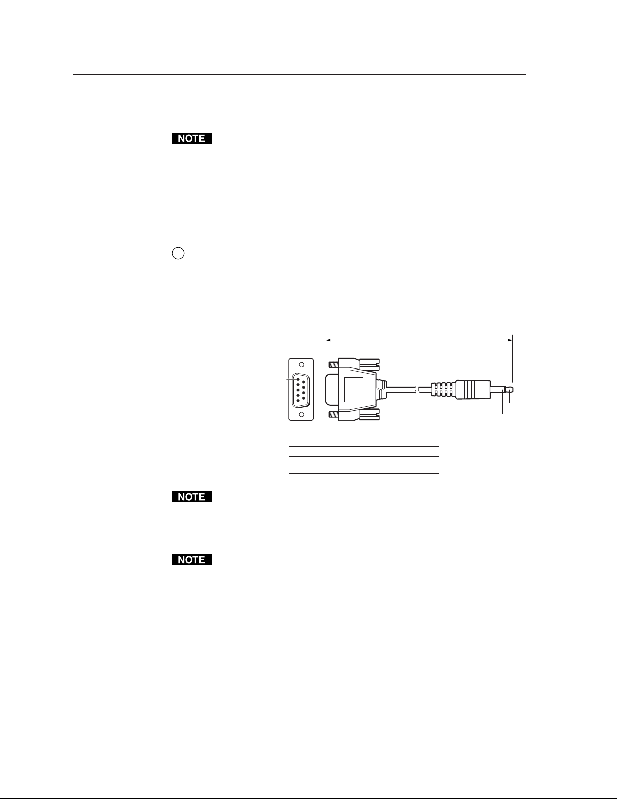
Front panel Config port — This 2.5 mm mini stereo jack serves the same
2
RS-232 function as the rear panel Host Control port, but it is easier to access
than the rear port after the MLC has been installed and cabled. Digital input
is not available on this port. The optional 9-pin D to 2.5 mm stereo mini TRS
RS-232 cable (part #70-335-01, shown below) can be used for this connection.
This port has the same protocol as the rear panel port mentioned above but
does not offer digital input.
PRELIMINARY
RS-232 protocol:
• 38400 baud
6 feet
(1.8 m)
• 1 stop bit
• no parity
• 8 data bits
• no flow control
1
5
6
9
9-pin D Connection TRS Plug
Pin 2 Computer's RX line Tip
Pin 3 Computer's TX line Ring
Pin 5 Computer's signal ground Sleeve
Part #70-335-01
Both configuration ports require 38400 baud communication. This is a higher
speed than many other Extron products use. The configuration software
automatically sets the connection for the appropriate speed. If using
HyperTerminal or a similar application, make sure the PC or control system
connected to these ports is set for 38400 baud.
Maximum distances from the MLC to the device being controlled may vary up
to 200 feet (61 m). Factors such as cable gauge, baud rates, environment, and
output levels (from the switcher and the device being controlled) all affect
transmission distance. Distances of about 50 feet (15 m) are typically not a
problem. In some cases the MLC may be capable of transmitting and
controlling a given device via RS-232 up to 250 feet (76 m) away, but the
RS-232 response levels of that device may be too low for the MLC to be able to
detect.
Tip
Ring
Sleeve (Gnd)
MLC 226 Series • Installation: Labeling, Cabling, Mounting2-4
Page 15

Bottom/rear panel and cabling
MLC 226 IP Rear Panel
R
C 3 4BC 5 6CS GAS G
Rx
Tx/IR
GROUND
PROJECTOR
RS-232/IR RS-232 12V
GROUND
PWR SNS
GROUND
+12V OUT
+12V OUT
A B C D E
CM/ IR SCP
IR IN
SCP COM
CONT MOD
C 1 2
A
RELAYS
IR/SERIAL OUT
HOST
CONTROL
1=D INPUT 2=Tx 3=Rx
5=GND, 38400, N, 8, 1
PRESS TAB WITH
TWEEKER TO REMOVE
LAN
41 2 3
5 6
S G
Tx
Rx
BAB
C
GROUND
GROUND
MLS PWR
+12V IN
MLC 226 IP Bottom Panel
Projector control (Projector RS-232/IR) and display power sensor port
1
CM/IR/SCP port
2
Relay ports (24 V, 1 A)
3
IR/Serial Output ports
4
MLS connector
5
PWR (power) connector
6
LAN (IP) connector and LEDs
7
LAN (IP)
Connector
Side View
7
PRELIMINARY
Projector/display connections
1
Projector control (Projector RS-232/IR) port (-5 VDC to +5 VDC) — Connect a
cable between the projector and the
left three poles of this 3.5 mm direct
insertion captive screw connector for RS-232 one- or two-way projector/
display control. Alternatively, the Tx/IR and Ground pins can be used for
one-way infrared signal output. From this port, commands from a projector
driver or user-defined command strings entered via the Windows-based
configuration program can be sent to the display device.
Connect a cable between the
right three poles of the Proj Cont port and
accessories such as an Extron Power Sensor. The Power Sensor can be used to
let the switcher know when the projector is on or off. If these pins are not
connected to a Power Sensor, the SNS and ground pins can be used for digital
input as can pin 1 and ground of the 9-pin D RS-232 Host Control port.
Digital input: pin 1 and the ground pin together act as a digital input port
(depending on configuration). This allows for an additional way to trigger
events or functions (such as triggering relays, issuing commands, or sending
an e-mail).
2-5MLC 226 Series • Installation: Labeling, Cabling, Mounting
Page 16

Installation: Labeling, Cabling, Mounting, cont’d
When configured as a digital input, this port will be in one of two states: 1
(on, high) or 2 (off, low). A closed circuit = a logic 1, an open circuit = a logic
0. Threshold voltages are <0.8 VDC = low, >2.0 VDC = high.
There is also a +5 VDC selectable pull-up resistor for this circuit.
Use the following illustrations as a wiring guide. Wiring will vary depending
on the projector model. In most cases the drivers are bidirectional, but
sometimes only the transmit (Tx) and ground connections will be needed for
projector control. For bidirectional RS-232 communication, the transmit,
ground, and receive pins must be wired at both the switcher and the projector.
PRELIMINARY
Rx
Tx/IR
GROUND
PROJECTOR
RS-232/IR
MLC 226
Bottom Panel
To a
projector
or display
GROUND
PWR SNS
Transmit (Tx)
Receive (Rx)
Ground ( )
+12V OUT
Ground ( )
Receive (Rx)
Transmit (Tx)
Bidirectional
Tx/IR
PROJECTOR
Bottom Panel
Rx
GROUND
PWR SNS
RS-232/IR
MLC 226
Transmit (Tx)
Receive (Rx)
Ground ( )
Projector
GROUND
+12V OUT
Panel
Power
sense
Ground ( )
+12VDC
Tip (+12 V)
Ring
(signal)
Sleeve ( )
3.5 mm Stereo Plug
Each projector or display may require different wiring. For details, refer to the
manual that came with the projector.
Maximum distances from the MLC to the device being controlled may vary up
to 200 feet (61 m). Factors such as cable gauge, baud rates, environment, and
output levels (from the switcher and the device being controlled) all affect
transmission distance. Distances of about 50 feet (15 m) are typically not a
problem. In some cases the MLC may be capable of transmitting and
controlling a given device via RS-232 up to 250 feet (76 m) away, but the
RS-232 response levels of that device may be too low for the MLC to detect.
To an Extron
Power Sensor
(60-271-01)
CM/IR/SCP port — You can connect up to four Extron control modules
2
(IRCMs, ACMs, RCMs), one Extron IR Link infrared signal repeater, and/or
an Extron SCP 226 control pad to this port to allow remote control of the
MLC 226 controller or other items. A maximum of six devices can be
connected to this port. Use the following diagram as a wiring guide.
The SCP 226 replicates the MLC’s front panel controls. The SCP 226 and the
IR Link can receive IR signals from an optional IR 402 remote control and
send them to the controller. Control modules can be used (once the MLC is
set up) to control VCRs, DVD players, tape decks, a projector lift, or screen
control. Refer to the appropriate device’s user’s manual.
The control modules, IR Link, and SCPs can be daisy chained, as shown in the
following diagram. Extron Comm-Link cable is recommended for these
connections.
MLC 226 Series • Installation: Labeling, Cabling, Mounting2-6
Page 17

IR IN
GROUND
+12V OUT
CONT MOD
A B C D E
CM/ IR SCP
MLC 226
Bottom
Panel
+12 VDC
A
Ground ( )
B
IRCM, ACM, RCM
C
Modulated IR (from IR Link)
D
SCP communication (IR)
E
SCP COM
SCP 226
PROJECTOR
ON
VOLUME
OFF
LIGHT
ON
LIGHT
OFF
LAPTOP
AUTO
IMAGE
D
IR Link
C
IRCM/ACM/RCM
B
Ground ( )
A
+12 VDC
IRCM-DV+
200' (61 m) max.
DVD
VCR
2
1
5
4
PC
IR
CONFIG
DVD & VCR CONTROL
DVD VCR
TITLE MENU
TV/VCR
ENTER
PLAY NEXT/FWD PAUSE STOP
PREV/REW
AUX
VIDEO
LECTERN
PC
SCP 226
Tx
Maximum =
2 SCPs
Per System
D
IR Link
B
Ground
A
+12 VDC
Maximum =
4 Control
Modules
(4 Module
Addresses)
3
6
TUNER
SIGNAL
Maximum =
1 IR Link
IR LINK
IR Link
The maximum total distance between the MLC 226 and a connected device is
200' (61 m).
This port provides up to 12 VDC for powering the SCP control pad or other
devices. The automatic current protection circuit for this port limits the draw
to 0.5 amperes.
If an IRCM/RCM/ACM is to be used in an MLC/SCP system, the control
modules connected to the SCP must be of the same kind/model and must be
addressed identically to the modules that are connected to the MLC. Refer to
the appropriate control module user’s manual for instructions on addressing
the control modules.
Any SCP control pad or control modules (CM, IRCM, ACM, RCM) used
with the MLC
will be affected by front panel security lockout (executive mode)
status changes.
PRELIMINARY
2-7MLC 226 Series • Installation: Labeling, Cabling, Mounting
Page 18

Installation: Labeling, Cabling, Mounting, cont’d
Relay ports (24 V, 1 A) — These six relays allow control of items such as room
3
lighting, window coverings, and display screens. These contacts may be used
to control any equipment as long as the contact specifications of a total of
24 volts at 1 ampere are not exceeded for each port. The pin assignments are
shown in the following picture.
Group B Group CGroup A
C 1 2
C 3 4BC 5 6
A
C
C 1 2
C 3 4BC 5 6CC 1 2
A
C 3 4BC 5 6
A
C
PRELIMINARY
RELAYS
Common Relay 2
Relay 1
Common Relay 4
RELAYS
Relay 3
These relays are normally open by default.
They can be configured via SIS commands or
the configuration software to operate as follows:
• on—relay closes and stays closed until
otherwise instructed
• off—relay opens and stays
open until otherwise
instructed
• toggle—relay changes from
open to closed or from
closed to open until
To / from
control
equipment
otherwise instructed
• pulse—momentary (timed) (press
to turn on, timeout to turn off)
Toggle off
Common
Relay On
On (Closed)
Common
or
On (Closed)
Toggle on
Relay Toggle
Common
Off (Open)
RELAYS
Common Relay 6
Relay 6
Relay 5
Common
C 1 2
C 3 4BC 5 6
A
RELAYS
Common
Common
Normally
Open (5)
C
Relay 5
All relays are
normally open.
Normally
Open (6)
Common
Relay Off
You can also use SIS commands or the configuration software to specify pulse
duration.
Via the configuration software, each relay can be associated with a front panel
button, or it can be operated independently.
MLC 226 Series • Installation: Labeling, Cabling, Mounting2-8
Off (Open)
Common
Turn
on
Off (Open)
Turn off after
Common
On (Closed)
Relay Pulse
a set period
Common
Off (Open)
Page 19

IR/Serial Output ports — Depending on how the MLC is configured via the
4
configuration software, these ports output either infrared signals or
unidirectional RS-232 signals for controlling various devices such as VCRs
and DVD players. Before it can be used for controlling a device, each port
must be set up via the configuration software for either IR or RS-232
communication and associated with a device driver.
The connector pins are labeled S (signal) and G (ground).
For RS-232 output (-5 VDC to +5 VDC), use the illustration below as a wiring
guide, then wire a serial cable into this captive screw connector.
RS-232 default protocol:
• 9600 baud
• no parity
• 8 data bits
• 1 stop bit
• pacing = 0 ms
To a
Controllable
Device
S GAS G
B
IR/SERIAL OUT
S G
C
S = Signal (Tx)
G = Ground
(15.2 m)
(See note.)
50'
Maximum distances from the MLC to the device being controlled may vary up
to 200 feet (61 m). Factors such as cable gauge, baud rates, environment, and
output levels (from the MLC and the device being controlled) all affect
transmission distance. Distances of about 50 feet (15 m) are typically not a
problem. In some cases the MLC may be capable of transmitting and
controlling a given device via RS-232 up to 250 feet (76 m) away.
For infrared (IR) output (0 to +5 VDC), wire an IR Emitter (2 emitters,
maximum, per port) as shown below for a modulated or demodulated signal
and ground. For specific information about wiring more than one IR Emitter
per port, refer to the Extron IR Emitter Installation Guide, part #68-808-01.
Alternatively, an Extron IR Broadcaster can be connected here if you need to
send out IR signals to a wider area than is possible for an IR Emitter. The IR
Broadcaster requires a +12 VDC power connection. The +12 V Out and
ground pins of the Projector port can be used to provide this power.
White Striped Wire
S = Signal (IR)
G = Ground
IR Emitter 1
PRELIMINARY
100'
S GAS G
B
IR/SERIAL OUT
S G
C
(30.5 m)
See chapter 4 for details on how to set up these ports for IR or RS-232 control.
2-9MLC 226 Series • Installation: Labeling, Cabling, Mounting
Page 20

Installation: Labeling, Cabling, Mounting, cont’d
MLS connector — For controlling an optional Extron switcher or other RS-232
5
controllable device, connect a cable between this 3.5 mm direct insertion
captive screw connector and the RS-232 port of the other device.
The commands issued from this port are standard Extron SIS™ commands, and
they follow the typical Extron protocol (9600 baud rate, 8 data bits, 1 stop bit,
no parity).
If you connect an optional switcher (such as an Extron MLS Series switcher) to
the MLC, you must connect a ground wire between the switcher and the
MLC, as shown in the following diagrams.
PRELIMINARY
MLC/IR
ABC
MediaLink
Switcher's
rear panel
MLC/IR port
100-240V 0.2A 50/60 Hz
MLS 506MA Rear Panel
NOTE You must connect
a ground wire
between the MLC
and MLS.
.5A MAX
INPUT 1
INPUT 2
VIDEO
R-Y
VIDEO
R-Y
Y
Y
B-Y
B-Y
C
C
L LRR LR
INPUT 3
INPUT 4
INPUT 5
VIDEO
R-Y
RH/
RH/
RH/
HV
HV
G
G
V
B
LR LR LR
GROUND
+12V OUT
GROUND
GROUND
PWR SNS
+12V OUT
A B C D E
CM/IR SCP
B
CONT MOD
G
V
B
C 1 2
IR IN
SCP COM
Y
B-Y
C
Rx
Tx/IR
PROJECTOR
RS-232/IR RS-232 12V
MLC 226
Bottom Panel
INPUT 6
RH/
HV
G
V
B
SENDLRRETURN
LR
C 3 4BC 5 6CS GAS G
A
RELAYS
RGB
HV
V
YUV
VIDEO
R-Y
S-VIDEO
Y
Y
B-Y
C
AUX/MIXEFFECTS
LR
BAB
IR/SERIAL OUT
FIXED VARIABLE
MONO AMPLIFIED OUTPUT
4 ohm
COMM 8 ohm 70V
MLC/IR RS232
AUDIO OUT
ABC
LRLR
CONTACT CLOSURE
S G
Tx
Rx
C
+12V IN
GROUND
GROUND
MLS PWR
Ground ( )
B
Receive (Rx)
A
Transmit (Tx)
NOTE If you use cable that
has a drain wire, tie
the drain wire to
ground at both
ends.
Transmit (Tx)
Receive (Rx)
B
A
Tx
Rx
AB
GROUND
MLS PWR
RS-232 12V
GROUND
+12V IN
+12 VDC input
MLC's
MLS and
Power
ports
Ground ( )
Ground all devices.
Connecting an MLC 226
to a MediaLink Switcher and
an external power supply
PWR (power) connector — To provide power to the MLC, connect a cable
6
between this port and a 12 VDC, 1 amp (maximum) power supply. See the
following diagram.
Power the controller via an external power supply, not from an Extron
switcher. The controller requires a separate 12 VDC power supply.
External
Power Supply
External
Power Supply
(12 VDC, 1 A max.
Tx
Rx
AB
MLS PWR
RS-232 12V
Connecting an MLC 226
to an external power supply
MLC 226 Series • Installation: Labeling, Cabling, Mounting2-10
Ground ( )
+12 VDC input
An external
power supply
(12 VDC, 1 A max.)
+12V IN
GROUND
GROUND
Ground all devices.
Check the power supply’s polarity before connecting it to the MLC. See the
following illustration.
Page 21

Smooth
LAN
Ridges
0.2” (5 mm) MAX.
AA
Power Supply
Output Cord
LAN connector and LEDs — An Ethernet connection can be used on an
7
SECTION A–A
PWR
12V
GROUND
+12V IN
MLC's
Power
Port
ongoing basis to connect and to control the MLC 226 (and the devices
connected to it) in an Ethernet network.
Plug a cable into this RJ-45 socket, and connect the other end of the cable to a
network switch, hub, router, or PC connected to an Ethernet LAN or the
Internet.
• For 10Base-T (10 Mbps) networks, use a Cat 3 or better cable.
• For 100 Base-T (max. 155 Mbps) networks, use a Cat 5 cable.
You will also need to configure this port before using it.
Activity LED — This yellow LED blinks to indicate
network activity.
Link LED — This green LED lights to indicate a good
network connection.
• Use a straight-
through cable
for connection
to a switch,
hub, or router.
• Use a
crossover
cable for
connection
directly to a
Clip Down
12345678
1
2345678
RJ-45
connector
Straight-through Cable
(for connection to a switch, hub, or router)
End 1 End 2
Pin Wire Color Pin Wire Color
1 white-orange 1 white-orange
2 orange 2 orange
3 white-green 3 white-green
4 blue4blue
5 white-blue5white-blue
6 green 6 green
7 white-brown7white-brown
8 brown8brown
Activity
LED
PC. Wire the
connector as
shown in the
tables at right.
Configure the
1&2
3&6
Twisted
Pairs
7&8
4&5
settings for this
port via either SIS commands or the
Windows-based configuration
program. See the programming
sections of this manual (chapters four
Pin Wire Color Pin Wire Color
Crossover Cable
(for direct connection to a PC)
End 1 End 2
1 white-orange 1 white-green
2 orange 2 green
3 white-green 3 white-orange
4 blue4blue
5 white-blue5white-blue
6 green 6 orange
7 white-brown7white-brown
8 brown8brown
and five) for details.
RJ-45
Por t
Link
LED
PRELIMINARY
LAN port defaults:
• MLC’s IP address: 192.168.254.254
• gateway’s IP address: 0.0.0.0
• subnet mask: 255.255.0.0
• DHCP: off
2-11MLC 226 Series • Installation: Labeling, Cabling, Mounting
Page 22

Installation: Labeling, Cabling, Mounting, cont’d
Side Panel Features: Reset Button and LED
Reset button and LED — Pressing this recessed
button causes various IP functions and Ethernet
connection settings to be reset to the factory
defaults. See “Resetting the unit” for details.
Resetting the unit
There are four reset modes (numbered 1, 3, 4, and 5
for the sake of comparison with an Extron IPL
product) that are available by pressing the Reset
button on the side panel. The Reset button is
recessed, so use a pointed stylus, ballpoint pen, or
Extron Tweeker to access it. See the following table
for a summary of the modes.
CAUTION
Review the reset modes carefully.
Using the wrong reset mode may result in unintended loss of flash
memory programming, port reassignment, or controller reboot.
The reset modes listed below close all open IP and Telnet connections and close
all sockets. Also, the following modes are separate functions, not a
continuation from Mode 1 to Mode 5.
MLC 226
Right Side
Reset
button
Reset
LED
PRELIMINARY
Reset Mode Comparison/Summary
Mode
Activation Result Purpose/Notes
1 Hold down the
recessed Reset button
while applying power
to the MLC.
3 Hold down the Reset
button for about 3 sec.
until the Reset LED
blinks once, then press
Reset momentarily
(<1 sec.) within 1 sec.
4 Hold down the Reset
button for about 6 sec.
until the Reset LED
has blinked twice
ce at 3 sec., again
(on
at 6 sec.). Then press
Reset momentarily
(for <1 sec.) within 1
second.
5 Hold down the Reset
button for about 9 sec.
until the Reset LED
has blinked three
times (once at 3 sec.,
again at 6 sec., again
at 9 sec.). Then press
Reset momentarily
(for <1 sec.) within 1
second.
The MLC reverts to the factory default
firmware.
MLC is powered on in this mode. All user
files and settings (drivers, adjustments, IP
settings, etc.) are maintained.
Mode 3 turns events on or off. During
resetting, the Reset LED flashes 2 times if
events are starting, 3 times if events are
stopping.
Mode 4
• Enables ARP capability.
• Sets the IP address back to factory default.
• Sets the subnet back to factory default.
• Sets the default gateway address back to
• Sets port mapping back to factory default.
• Turns DHCP off.
• Turns events off.
Reset LE
during reset.
Mode 5 performs a complete reset to factory
defaults (except the firmware).
• Does everything mode 4 does.
• Resets almost everything that can be set via
• Clears driver-port associations and port
• Removes button configurations.
• Resets all IP options.
• Removes scheduling settings.
• Removes/clears all files from switcher.
The Reset LED flashes 4 times in quick
success
Event scripting will not start if the
the factory default.
D flashes 4 times in quick succession
the Real Time Adjustments part of the
configuration program: all audio settings,
limit initial power up volume, power
up/down delay, auto power down
misc. options. This does not affect an
optional MLS switcher, however.
configurations (IR/RS-232).
ion during the reset.
, and
Use mode 1 to
remove a version of
firmware if
incompatibility
issues arise.
Events must be
turned on if you
want to change IP
settings or
scheduling.
Mode 4 enables you
to set IP address
information using
ARP and the MAC
address.
Mode 5 is u
you want to start
over with
configuration and
uploading, and also
to replace events.
seful if
MLC 226 Series • Installation: Labeling, Cabling, Mounting2-12
Page 23

Pinout guide
The illustration below summarizes the pin assignments of all of the MLC’s bottom
panel connectors that are covered in detail on pages 2-5 to 2-12.
MLC 226
Bottom Panel
PROJECTOR
Tx/IR
Rx
RS-232/IR RS-232 12V
GROUND
PWR SNS
GROUND
+12V OUT
A B C D E
CM/ IR SCP
+12V OUT
GROUND
CONT MOD
IR IN
SCP COM
C 1 2
A
RELAYS
C 3 4
B
C 5 6
C
S G
A
IR/SERIAL OUT
S G
BAB
S G
C
Rx
MLS PWR
Tx
GROUND
GROUND
+12V IN
Transmit (Tx)
Receive (Rx)
Ground ( )
Power sense
Ground ( )
+12 VDC
+12 VDC
Ground ( )
IRCM, ACM, RCM
Modulated IR (for IR Link)
SCP communication (IR)
Common
Relay 1
Relay 2
Signal (IR)
Ground
Receive (Rx)
Transmit (Tx)
Ground ( )
Ground ( )
+12 VDC input
To a projector or display
To an Extron
Power Sensor
To / from optional Extron control modules,
IR Link IR repeater, or SCP control pads
To / from control equipment
(screen control motors, lights, etc.)
To an IR Emitter, IR Broadcaster,
or IR or serial (RS-232) controllable device
OR
To an optional Extron switcher
From an external 12 VDC, 1 A (max.) power supply
Digital
input
Mounting the MLC
Once the system has been cabled, configured (see chapter four), and tested, the
controller can be installed in the wall, furniture, equipment rack, or Euro Channel.
1
2
2
1
Mounting screws (4) — Use these to attach the MLC to a wall, furniture, or
1
other mounting surface.
Faceplate attachment screws (4) — Do not remove these screws during or
2
after mounting. They attach the faceplate to the MLC unit. Removing these
screws during or after mounting will cause the MLC to detach, and it may
then fall down into the wall or furniture.
PROJECTOR
ON
VOLUME
OFF
LIGHT
ON
LIGHT
OFF
AUTO
IMAGE
VCR
1
4
LAPTOP
PRELIMINARY
1
2
AUX
DVD
VIDEO
3
2
5
6
LECTERN
PC
PC
IR
CONFIG
MLC 226 IP
2
1
2-13MLC 226 Series • Installation: Labeling, Cabling, Mounting
Page 24

PRELIMINARY
Installation: Labeling, Cabling, Mounting, cont’d
Mounting the MLC to an electrical box or mud ring
1. With power disconnected at the source, insert the MLC into the wall or
furniture.
2. Mount the MLC to the wall box or mud ring mounting bracket with the
provided machine screws (mounting screws, as shown in the following
illustrations).
If the MLC (and any accessories such as control modules or an IR Link) is not
mounted to a grounded metal wall box,
• Ground each faceplate directly to an earth ground. Or...
• Tie each faceplate to its circuit board and power supply via a ground pin on
one of the connectors.
Do
not tie a product’s faceplate to both a separate earth ground and the circuit
ground (via a connector pin). If you tie a product to two different ground
sources, you may introduce ground loops or other grounding-related problems
into the system.
For the installation to meet UL
requirements and to comply
with National Electrical Code
(NEC), the MLC must be
installed in a UL approved
junction box. The end user or
installer must furnish the
junction box; it is not included
with the MLC.
O
T
U
A
E
G
A
IM
F
F
O
E
T
U
ON
M
A
ID
V
D
V
D
R
C
V
OP
PT
LA
R
O
T
C
E
J
O
R
P
E
M
U
L
O
V
3-gang Wall Box
X
U
O
E
C
P
2
5
1
4
G
I
F
N
O
C
R
I
n
o
r
t
x
E
3
6
Extron
MLC 226
Sheet Rock
Backing Clip
0.75" #6-32 Screw
Sheet Rock
Backing Clip
1.25" #6-32 Screw
Backing Clip can
be in either orientation.
See Detail A or Detail B.
Mounting the MLC to an electrical box or mud ring
MLC 226 Series • Installation: Labeling, Cabling, Mounting2-14
Detail A
Detail B
Mounting Bracket
Mounting Bracket
2
5
C
IG
F
N
O
3
6
Extron
MLC 226
UX
A
DEO
VI
DVD
VCR
PC
AUTO
GE
A
IM
OFF
APTOP
L
ON
MUTE
PROJECTOR
1
4
IR
UME
VOL
ron
Ext
Page 25

Mounting the MLC to a wall or furniture
1. Remove the four faceplate attachment screws and remove the original
faceplate, if applicable.
2. Attach the optional lectern mounting faceplate to the MLC with the screws
removed in step 1.
3. With power disconnected at the source, insert the MLC into the wall or
furniture.
4. Fasten the MLC and faceplate directly to the furniture or wall using wood
screws.
If the MLC (and any accessories such as control modules or an IR Link) is not
mounted to a grounded metal wall box,
• Ground each faceplate directly to an earth ground. Or...
• Tie each faceplate to it’s circuit board and power supply via a ground pin on
one of the connectors.
Do
not tie a product’s faceplate to both a separate earth ground and the circuit
ground (via a connector pin). If you tie a product to two different ground
sources, you may introduce ground loops or other grounding-related problems
into the system.
For the installation to meet UL requirements and to comply with National
Electrical Code (NEC), the MLC must be installed in a UL approved junction
box. The end user or installer must furnish the junction box; it is not included
with the MLC. See “Mounting the MLC to an electrical box or mud ring” on
the previous page.
Rack mounting an MLC 226 IP L
1. Attach an MLC 226 IP L to an optional rack mounting faceplate (UCM-RAAP)
with the provided mounting machine screws.
2. With power disconnected at the source, fasten the MLC and faceplate to the
rack using the supplied machine screws as shown in the following
illustration.
Extron
UCM-RAAP
X
U
A
O
VIDE
3
VD
6
D
2
R
5
VC
O
R
C
T
O
P
U
T
1
A
E
G
A
JEC
4
M
I
RO
P
OFF
P
O
T
P
TE
A
U
L
M
IG
F
ON
N
O
C
E
M
IR
U
L
O
V
xtron
E
Rack mounting the MLC 226 IP L
Extron
MLC 226 L
PRELIMINARY
2-15MLC 226 Series • Installation: Labeling, Cabling, Mounting
Page 26

Installation: Labeling, Cabling, Mounting, cont’d
Mounting the MLC in a Euro Channel
1. Remove the four faceplate attachment screws and remove the original
faceplate, if applicable.
2. Attach the optional MLM 226 EC or MLM 226 AAP EC faceplate to the MLC
with the screws removed in step 1.
3. With power disconnected at the source, insert the MLC into the Euro Channel.
For wider types of Euro Channels, you may need to insert a spacer plate first.
4. Mount the controller to the Euro Channel by attaching the faceplate to the two
backing plates using four #4-40 mounting screws. See the illustration below.
Make sure that the Euro Channel is grounded to an earth ground before
completing the installation.
PRELIMINARY
3
6
R
I
C
P
G
I
F
N
O
C
Extron
MLC 226 EC
X
U
O
A
E
ID
V
D
V
D
R
C
2
V
5
O
P
T
E
1
O
U
T
G
4
A
P
A
A
L
IM
E
T
U
R
M
O
T
C
OFF
E
J
O
OFF
R
P
ON
E
ON
M
U
L
O
V
Extron
Euro Channel
Backing Plate
Mounting the MLC 226 to a Euro Channel
MLC 226 Series • Installation: Labeling, Cabling, Mounting2-16
Page 27

MLC 226 MediaLink™ Controllers
Chapter Three
3
Front Panel Features and
Basic Operation
Projector Control
Front Panel Features and Operation
Front Panel Security Lockout (Executive Modes)
Page 28

Front Panel Features and Basic Operation
Projector Control
The MLC can control a projector or other display device by using IR or RS-232
control. The MLC must be configured for projector control in one of the following
ways before it will send commands to the projector:
• An IR or an RS-232 driver file can be installed from a disk or downloaded from
the Extron Web site into the MLC.
• RS-232 command strings can be entered directly from a host computer using the
supplied Windows-based software.
• IR commands can be entered directly from an IR remote control through IR
learning to create a driver that the MLC can use. IR learning is convenient for
installing new or updated commands into the MLC in the field.
See chapter 4 and the MLC 226/104 Configuration Program software for details on
setting up the MLC and for downloading, programming, or learning projector
control commands.
Front Panel Features and Operation
Many features must be set up in order for the MLC to function. See chapter 4,
“Software- and Web Page-based Setup and Control”, for information about the
MLC 226/104 Configuration Program, which you must use to set up most
features of the MLC.
PRELIMINARY
Buttons
MLC 226 IP
Front Panel
1
PROJECTOR
ON
OFF
VOLUME
4 5 6
2 3
LIGHT
ON
LIGHT
OFF
AUTO
IMAGE
VCR
1
4
LAPTOP
IR
DVD
PC
2
5
CONFIG
AUX
VIDEO
3
6
LECTERN
PC
7
MLC 226 IP
The MLC 226 Series controllers have backlit buttons. The functions, events, and
scripts associated with these buttons are available in all models. Pressing the
corresponding button on the Extron IR 402 remote control or an Extron SCP 226
keypad will cause that button’s functions to be executed exactly as if you had
pressed a front panel button.
Each Projector On/Off, Function/Room, and Input button can be set up to perform
up to six functions, which can be combinations of the following options:
•a driver operation—execute an RS-232 or IR control command that is part of a
device driver (for a projector, VCR, DVD, audio source, etc.)
MLC 226 Series • Front Panel Features and Basic Operation3-2
Page 29

•a relay operation—turn relays on or off, or toggle or pulse a relay
• an internal operation—
• change a front panel button’s brightness, color, or flashing
• execute an SIS command for the switcher, or insert delays between executed
commands
• turn the digital output on or off, toggle it, or pulse it
•a user-defined RS-232 operation—issue a non-driver-associated RS-232 com-
mand (one that you programmed separately) via a specific port (IR/Serial Out A,
B, C; or the projector control port) or an internal command for the MLC, itself.
By default all buttons illuminate brightly when selected (active), and light dimly
when deselected. The button caps are removable so the button labels can be
changed.
Projector On/Off buttons — After they have been configured, press the On
1
button to turn the projector or display device on, and press the Off button to
power it off. Only one of these two buttons can be selected (active) at once.
Via the configuration software, other functions and relays can be associated
with each of these buttons.
Function/room control buttons and 3 input selection buttons — Each of
2
these buttons can be set several functions apiece, depending on how the MLC
is set up and what mode is active. Each button can be configured to control
the MLC’s relays, execute the IR or RS-232 commands of your choice, or
trigger event scripts and/or port monitoring.
The relays can be used to control items in the room such as a projector lift,
screen motor, or lighting. For details on how the relays operate and can be
configured, see the installation instructions in chapter 2 and the configuration
software information in chapter 4.
Function/room control buttons — These have the same
2
capabilities as the input selection buttons (
3
), but are
typically used for triggering commands and functions other
than input selection. The F1, F2, and F3 buttons on the
Relay
Relay
optional IR 402 remote control correspond to these buttons.
By default these three buttons are each associated with a
Relay
latching relay, as shown at right. However, any softwarebased configuration, regardless of whether the function
buttons are configured or not, overrides the default associtions between
these buttons and the relays.
1
PRELIMINARY
2
3
Input selection buttons — These buttons,
3
labeled 1 through 6, have the same capabilities
as the function/room buttons (
2
) and can be
configured to perform a variety of functions.
By default they are a mutually exclusive group
(only one of these buttons can be selected at a
1!
1
4
4!
time), and each button has an Extron input
switching SIS command (1!, 2!, 3!, and so forth)
associated with it and bidirectional communication via the MLC’s MLS
RS-232 port. See the picture at right.
Alternatively, the buttons can be reconfigured (via software) to select
different inputs and to trigger different commands to be issued. See
chapters 4 and 5 for details.
Press an input selection button to select the desired audio and video
input on the projector or an optional Extron switcher. The button lights
brighter and remains lit while an audio-video input is selected.
3!
2!
3
2
5
6
5!
6!
3-3MLC 226 Series • Front Panel Features and Basic Operation
Page 30

Front Panel Features and Basic Operation, cont’d
When these input selection buttons are configured for input
switching, there is a default 0.5 second delay between when one
input is selected and when a different input can be selected. This
allows time for the projector to adjust to the change of sync signals.
The delay period is adjustable.
If the MLC is used without an optional switcher and the MLC has been
set up for use with a projector, the selectable inputs on the MLC
correspond to the number of inputs available on the projector. If an
optional Extron switcher is connected to the MLC, all six input selection
buttons will be selectable. Which buttons are and aren’t part of the
switching rotation can be determined/set by the projector driver or via
the Windows-based configuration program.
When an input selection button is part of the switching rotation,
pushing that button causes the MLC to send out an SIS input
change command via the MLSRS-232
connector
control commands out the Projector
RS-232/IR port, triggering a relay, or
sending an IR or serial command via an
IR/Serial Out port.
The standard Extron SIS commands sent
via the MLS connector are fixed and cannot be altered. The
command for each input is shown at right.
in addition to sending projector
Button Command
Input 1 1!
Input 2 2!
Input 3 3!
Input 4 4!
Input 5 5!
Input 6 6!
PRELIMINARY
Volume control
4
Range-based Volume Adjustment
Minimum,
0% of Max.
Volume
1% to 19%
of Max.
Volume
Volume knob and LEDs — Rotate this knob to adjust the audio volume.
Volume can be adjusted via this front panel knob or via RS-232/Telnet/Web
browser control. The included configuration software lets you select whether
this knob will control the projector’s audio levels or the optional switcher’s
audio levels. If the knob controls the projector’s audio levels, you can specify
incremental adjustments or range-based adjustments (via device driver only).
See chapter 4 and the MLC 226/104 Configuration Software Help file for
details.
If the MLC is configured for use with a MediaLink Switcher or for some
projectors, the MLC’s LEDs light to indicate volume ranges (with steadily lit
LEDs) and minimum/maximum volume limits (with flashing LEDs), as
shown in the following diagram.
VOLUME VOLUME VOLUME VOLUMEVOLUM EVOLUM EVOLUM E
20% to 39%
of Max.
Volume
40% to 59%
of Max.
Volume
60% to 79%
of Max.
Volume
80% to 99%
of Max.
Volume
100% of
Max.
Volume
If the MLC is configured for increment/decrement volume adjustment, the
LEDs scroll up/down briefly. See the example below.
Increment/Decrement-based Volume Adjustment
VOLUM E
VOLUM E
MLC 226 Series • Front Panel Features and Basic Operation3-4
Page 31

IR signal sensors
These sensors allow for IR
remote control of the MLC
and for IR learning. The IR
remote control must be
pointed directly at these
devices for best results.
IR control receiver — This
5
larger infrared receiver
accepts IR signals from the
Extron IR 402 infrared
remote control, which
mimics the MLC’s front
panel controls.
IR learning receiver — This
6
smaller sensor receives and
“learns” commands from other devices’ infrared remotes in order to control
the projector or input devices such as a VCR or DVD player. IR learning of
projector control codes is only necessary if there are no RS-232 codes available
for that projector or if you need to customize the driver. The IR learning
procedure is discussed in the control software and later in this manual. See
chapter 4 for IR learning procedures. This receiver accepts infrared signals of
from 30 kHz to 62 kHz.
Configuration port
Config port — This is a front panel version of the rear panel Host Control
7
port (the 9-pin D connector), and it is independent of that port. This port
makes it possible to upload and configure device drivers and also to initiate
IR learning via a front panel connection after the MLC has been installed.
4
LAPTOP
IR
40 40
30 feet
max.
5
PC
CONFIG
IR 402
LECTERN
PC
6
MLC 226 IP
MLC 226
or
MLC 226 IP
IR LearningControl
LAPTOP
4
IR
15 15
1 2 3
4 5 6
7 809
5
6
LECTERN
PC
PC
CONFIG
MLC 226 IP
2"–12"
(4–30 cm)
Connect a Windows-based PC or an RS-232 control system to this 2.5 mm
mini stereo-style (tip-ring-sleeve) connector. You can use the Extron 9-pin D
to 2.5 mm stereo mini TRS RS-232 cable (part #70-335-01) or make your own
cable. See chapter 2 for a wiring diagram and port protocol.
This port requires 38400 baud communication, a higher speed than many other
Extron products use. The MLC configuration software automatically sets the
connection for the appropriate speed. If using HyperTerminal or a similar
application, make sure the PC connected to these ports is set for 38400 baud.
Optional Control Modules and IR 402 Remote Control
The MLC can “learn” IR commands from a VCR’s, DVD’s, tape deck’s or other
device’s remote control, allowing you to create an IR driver file that can be
incorporated into the MLC’s event scripts. A command can be associated with each
of the buttons on an optional infrared control module (such as the Extron
IRCM-VCR, IRCM-DVD, IRCM-DVD+, IRCM-DV+, or IRCM-Tape) in order to
allow limited control of source devices. ACM control modules provide limited
remote control of adjustments to a slaved MediaLink Switcher (MLS).
PRELIMINARY
3-5MLC 226 Series • Front Panel Features and Basic Operation
Page 32

Front Panel Features and Basic Operation, cont’d
The control module must be connected to the MLC before you can perform IR
learning for the module’s buttons.
A total of four control modules (a maximum of four control
module addresses) can be installed with this MLC. Refer to the
Control Modules User’s Manual and the Relay Control Modules
User’s Manual for installation details. See chapter 4 of this
manual for special instructions for the IRCM-DV+.
PRELIMINARY
VCR CONTROL
REW PLAY FWD PAUSE STOP
IRCM-VCR
TAPE DECK
REW PLAY FWD PAUSE STOP
IRCM-Tape
DVD CONTROL
REW PLAY NEXT PAUSE STOP
IRCM-DVD
DVD CONTROL
MENU
TITLE
ENTER
PLAY NEXT PAUSE STOP
REW
Tx
Tx
Tx
Tx
AUDIO CONTROL
INPUT LEVEL MIX LEVEL MUTE
TONE CONTROL
BASS TREBLE
ROOM CONTROL
SCREEN POSITION LIGHTING
SCREEN POSITION
DOWN UPSTOP
MAX/
MIN
ACM-Level
MAX/
MIN
ACM-Tone
ON / OFF
RCM-SCLT
RCM-SC
IR 402
IR remote control
IRCM-DVD+
Optional IRCM, ACM, and RCM control modules
The buttons on the optional IR 402 remote duplicate the MLC’s front panel controls
and also those of a VCR and a DVD player for normal operation. The IR 402 can
also be used to control a MediaLink Switcher. The controller or switcher responds
to commands from the IR 402 remote as if the corresponding button or knob were
pressed or turned on the controller or switcher.
From a distance of no more than 30 feet and within 40° of the axis, the IR 402 sends
infrared (IR) signals to
• a MediaLink Controller via the controller’s front panel IR pickup device or the IR
pickup device of an optional IR Link IR signal repeater.
• a MediaLink Switcher via a connected IR Link. The switcher can receive signals
from the IR 402 remote control only via an IR Link.
The IR 402 remote’s Display Power buttons and the VCR and DVD control buttons
will not function until commands have been stored in the MLC’s memory.
IR commands are transmitted from the MLC’s Projector RS-232/IR port (via hard
wiring) and IR ports (via IR Emitters or optional IR Broadcaster) when the
corresponding button is pressed on the remote or on the controller’s, SCP’s, or
MLC 226 Series • Front Panel Features and Basic Operation3-6
Setup operations cannot be performed from the remote control.
Page 33

control module’s front panel. Refer to the Control Modules User’s Manual.
Front Panel Security Lockout (Executive Mode)
To prevent accidental changes to settings, the MLC features front panel security
lockout (executive) modes for disabling access to controls. When panel lockout is
enabled, the user cannot operate buttons or volume knobs on the MLC’s front
panel, an IR 402 remote control, SCPs control pad, or control modules. Functions
and adjustments can still be made only via the software or SIS commands via RS232, Telnet, or Web browser control. The Simple Instruction Set (SIS™) command 3X
corresponds to this mode. For details, see chapters 4 and 5.
Preparing the MLC for front panel lockout
1. Connect cables and power on the MLC and the host computer.
2. Install and start the configuration software. See chapter
4.
3. Click on the Tools drop-down menu and select PIN
Manager.
4. Click a radio button (Admin PIN Enabled or Both PINs
Enabled) to enable personal identification number
(PIN) use.
5. Set PINs. One PIN can be assigned for those with
administrator access, and another PIN can be assigned
for users. Each PIN must consist of four digits, each of
which is a number from 1 to 6. By default the
Administrator PIN is 1346 and the User PIN is 0000.
6. Click the Take button and close the PIN Manager.
7. Exit the configuration software, if desired.
PRELIMINARY
3-7MLC 226 Series • Front Panel Features and Basic Operation
Page 34

Front Panel Features and Basic Operation, cont’d
Enabling and disabling front panel lockout
Make sue the projector is off before using a PIN to lock the front panel.
Locking the Front Panel of an
MLC 226 Series Controller
1 2
Press and hold both
Projector On/Off buttons
simultaneously.
The Projector On/Off
buttons light green, the
other buttons dim, and the
bottom Volume LED blinks.
1
PROJECTOR
OFF
LIGHT
ON
LIGHT
OFF
AUTO
IMAGE
ON
VOLUME
While still pressing the
Projector buttons, enter the
PIN. Use the input selection
buttons as a 6-key numeric
keypad; press one button at
a time.
One green Volume LED
lights at a time as the buttons
are pressed.
2a 2b
VCR
1
4
LAPTOP
VIDEO
3
2
5
6
LECTERN
PC
PC
AUX
DVD
2c 2d
This example shows the
default administrator
PIN: 1, 3, 4, 6.
Release
buttons.
If the correct PIN was entered, the green Volume LEDs flash and
all buttons flash red twice, indicating that front panel is locked, then
return to the way they were lit before front panel lockout was set.
PROJECTOR
OFF
OFF
LIGHT
ON
LIGHT
OFF
AUTO
IMAGE
LIGHT
ON
LIGHT
OFF
AUTO
IMAGE
ON
VOLUME
all
If the incorrect PIN was entered, no buttons flash, the green
Volume LEDs turn off, and the red (top) LED blinks. Then the
buttons light as they were lit before front panel lockout was set.
PROJECTOR
ON
VOLU ME
VCR
1
4
LAPTOP
VCR
1
4
LAPTOP
DVD
DVD
AUX
VIDEO
3
2
5
6
LECTERN
PC
PC
AUX
VIDEO
3
2
5
6
LECTERN
PC
PC
PRELIMINARY
Unocking the Front Panel of an
MLC 226 Series Controller
1 2
Press and hold both
Projector On/Off buttons
simultaneously.
The Projector On/Off
buttons light green, the
other buttons dim, and the
bottom Volume LED blinks.
1
PROJECTOR
OFF
LIGHT
ON
LIGHT
OFF
AUTO
IMAGE
ON
VOLUME
While still pressing the
Projector buttons, enter the
PIN. Use the input selection
buttons as a 6-key numeric
keypad; press one button at
a time.
One green Volume LED
lights at a time as the buttons
are pressed.
2a 2b
VCR
1
4
LAPTOP
VIDEO
3
2
5
6
LECTERN
PC
PC
AUX
DVD
2c 2d
This example shows the
default administrator
PIN: 1, 3, 4, 6.
Release
buttons.
If the correct PIN was entered, the green Volume LEDs flash and all
buttons flash green twice, indicating that front panel is locked, then
return to the way they were lit before front panel lockout was set.
PROJECTOR
OFF
OFF
LIGHT
ON
LIGHT
OFF
AUTO
IMAGE
LIGHT
ON
LIGHT
OFF
AUTO
IMAGE
VCR
1
4
LAPTOP
VCR
1
4
LAPTOP
ON
VOLUME
all
If the incorrect PIN was entered, no buttons flash, the green
Volume LEDs turn off, and the red (top) LED blinks. Then the
buttons light as they were lit before front panel lockout was set.
PROJECTOR
ON
VOLU ME
When front panel lockout is enabled, if a button is pressed, the button flashes red,
but no change occurs. Nothing—not input switching,
projector control, room control, volume adjustment, or any
other knob- or button-executable function—results from
front panel actions when lockout is active. Changes can still
be made via RS-232 or Ethernet control.
DVD
DVD
AUX
VIDEO
3
2
5
6
LECTERN
PC
PC
AUX
VIDEO
3
2
5
6
LECTERN
PC
PC
MLC 226 Series • Front Panel Features and Basic Operation3-8
If PINs Disabled is selected via the PIN Manager
drop-down box in the configuration software, front
panel lockout can’t be enabled/disabled by anyone
(with or without a PIN) via the front panel.
The PIN can be entered via either the MLC or the
SCP.
Page 35

MLC 226 MediaLink™ Controllers
Chapter Four
4
Software-and Web Page-based
Setup and Control
Configuring the Hardware
Configuration Software for Windows
Embedded Web Pages
Controlling the MLC 226 IP via Global Viewer
®
™
Page 36

PRELIMINARY
Software- and Web Page-based Setup and Control
An MLC 226 Series controller must be configured before use or it will not be able
to control other devices. The MLC 226 IP can be configured and controlled via a
host computer attached to the rear panel Host Control port or LAN port, or the
front panel Config port. See chapter 2 for pin assignments and other details on the
configuration and control ports.
• The primary means for configuring the controller is by using the supplied
software, which can also be used to control the MLC. This method requires a
properly configured PC with Windows
of Windows installed.
• Alternatively, the default Web pages embedded within the MLC 226 IP provide
a means to perform some setup, adjustment, and control via a Web browser
from any type of network-enabled computer.
• The third way to control and configure the controller is by using Simple
Instruction Set (SIS) commands via Telnet, a Web browser, or RS-232. SIS
commands are discussed in detail in chapter five.
Configuring the Hardware
To function together, both the PC and the MLC 226 IP must be configured
correctly. Unless you use an RS-232 connection for all setup and communication
with the controller, the PC must be network-capable with the proper protocols,
and the MLC 226 IP must be set up so it can be connected to a LAN (local area
network). Please note that some settings can be configured only via IP.
The first time you connect a PC to the controller via IP, you must temporarily
configure the PC to communicate with the controller Then you must change the
controller’s default settings (IP address, subnet mask, and [optional]
administrator name and password) in order to use the unit on an intranet (LAN)
or on the Internet (WAN). After you have set up the MLC 226 IP for network
communication, you can reset the PC to its original network configuration.
MLC 226 IP’s RS-232 protocol:
• 38400 baud
• 8 data bits
• 1 stop bit
• No parity
• No flow control
©
2000, Windows XP, or a higher version
MLC 226’s LAN port defaults:
• MLC’s IP address: 192.168.254.254
• Gateway’s IP address: 0.0.0.0
• Subnet mask: 255.255.0.0
• DHCP: off
• Link speed and duplex level: autodetected
4-2
MLC 226 Series • Software-and Web Page-based Setup and Control
Both configuration ports require 38400 baud communication. This is a higher
speed than many other Extron products use. The MLC 226/104 Configuration
Program automatically sets the connection for the appropriate speed. If using
HyperTerminal or a similar application, make sure the PC or control system
connected to these ports is set for 38400 baud.
Page 37

Setting up the PC for IP communication
You need a Windows-based (Windows 2000, XP, or higher) PC equipped with an
operating network adapter. To allow your PC to work with Extron’s Ethernetcontrolled products, the TCP/IP protocol must be installed and properly
configured.
If you use an existing Ethernet LAN intranet, your network administrator can
provide you with a unique IP address for the controller or confirm whether you
need to set up the MLC 226 IP for DHCP (Dynamic Host Configuration Protocol) to
have an address assigned automatically when you sign on.
1. Open the Network Connections page as follows:
• Locate and right-click on My Network
Places on the Windows (2000, XP, or
higher) desktop, then click on
Properties.
or
• Click on the Start menu, click on Settings (if needed), click on Control
Panel, then double-click on Network and Dial-up Connections.
2. Right-click on Local Area Connection, then select Properties.
3. Select Internet Protocol (TCP/IP) and
click on the Properties button. If
Internet Protocol (TCP/IP) is not on
the list, it must be added (installed).
Refer to the Windows user’s manual
or the Windows online help system
for information on how to install the
TCP/IP protocol.
PRELIMINARY
MLC 226 Series • Software-and Web Page-based Setup and Control
4-3
Page 38

Software- and Web Page-based Setup and Control, cont’d
4. Write down the PC’s current IP address and subnet mask below. If your PC
is set to “Obtain an IP address automatically,” make a note of that, instead.
You will need to restore these settings to the PC later.
IP address:
. . . .
Subnet mask:
. . . .
5. Change the PC’s IP address so it can communicate with the MLC 226 IP and
change the controller’s IP settings.
a. Select the “Use the following IP address:” radio button.
b Enter the following values, as shown below:
IP address: 192.168.254.253
Subnet mask: 255.255.0.0
Default gateway: blank or 0.0.0.0
PRELIMINARY
c Click on the OK button to save the changes and exit the network setup.
Reboot the PC, if required, for the changes to become effective.
6. Plug one end of a Category 5 network/Ethernet crossover cable into the
MLC’s Ethernet (LAN) connector. Refer to chapter two for RJ-45 LAN
connector wiring. Plug the other end of the Ethernet cable into the Ethernet
port on the PC.
If a network hub or switch is used between the PC and the MLC 226 IP, use a
straight-through Category 5 cable instead of a crossover cable.
7. Set up the MLC’s IP address. See “Setting up the MLC 226 IP (at initial startup) for IP communication” below.
8. Restore the PC’s previous IP configuration by following steps 1, 2, 3, and 5 but
using the PC’s original IP address settings you wrote down in step 4.
4-4
MLC 226 Series • Software-and Web Page-based Setup and Control
Page 39

Setting up the MLC 226 IP (at initial start-up)
for IP communication
When you power on the MLC 226 IP for the first time, there are three ways to set
up the controller’s IP address:
• Use the ARP command.
• Use a Web browser.
• Use the supplied configuration software.
Once the controller has been reconfigured, an Ethernet (intranet or Internet)
connection can subsequently be used to contact, configure, or control it.
Both your computer and the MLC must be connected to the same LAN.
Alternatively, you can use a crossover Ethernet cable to connect the controller
directly to your computer’s Ethernet card.
The following instructions assume that you have already configured the
Windows-based PC, connected it to the MLC 226 IP’s LAN port, and powered on
the controller.
Configuring the controller using the ARP command
You can use the ARP (address resolution protocol) command to set up an IP
address for the controller. The ARP command tells your computer to associate
the controller’s MAC address with the assigned IP address. You must then use
the ping utility to access the controller, at which point the controller’s IP address
is reconfigured.
Use ARP to configure the MLC 226 IP’s IP address as follows:
1. Obtain a valid IP address for the controller from your network
administrator.
2. Obtain the controller’s MAC address (UID #) from the label on its rear, top, or
side panel. The MAC address should have this format: 00-05-A6-xx-xx-xx.
3. If the MLC has never been configured and is still set for factory defaults, go
to step 4. If not, perform a Mode 4 system reset. For detailed information on
reset modes, see “Resetting the unit” in chapter two.
CAUTION
4. At the PC, access the MS-DOS command prompt, then enter the arp –s
command. Enter the desired new IP address for the MLC and the
MLC 226 IP’s MAC address. For example:
arp –s 10.13.170.15 00-05-A6-00-0A-90
The MLC 226 IP must be configured with the factory default IP address
(192.168.254.254) before the ARP command is executed, as described
below.
PRELIMINARY
MLC 226 Series • Software-and Web Page-based Setup and Control
The MAC address is listed on the controller’s rear or bottom panel.
After the arp -s command is issued, the controller changes to the new address
and starts responding to the ping requests, as described in the next step.
4-5
Page 40

Software- and Web Page-based Setup and Control, cont’d
5. Execute a ping command by entering “ping” followed by a space and the
new IP address at the command prompt. For example:
ping 10.13.170.15
The response should show the controller’s new IP address, as shown
below.
You can reconnect using either Telnet or a Web browser to verify that the
update was successful.
6. After verifying that the IP address change was successful, enter and issue the
arp –d command at the DOS prompt. For example:
arp –d 10.13.170.15 removes 10.13.170.15 from the ARP table
or
arp –d* removes all static IP addresses from the ARP table.
7. After configuring the controller, remember to change your PC’s TCP/IP
settings back to their original configuration.
PRELIMINARY
Configuring the MLC via a Web browser
The default Web pages that are preloaded on the MLC 226 IP are compatible with
the Internet Explorer Web browser (version 5.5 or higher).
1. Obtain a valid IP address for the controller from your network
administrator.
2. Launch the Web browser (Internet Explorer) on the connected PC (for which
you set up the network configuration earlier), and enter “http://
192.168.254.254/” in the address box. The MLC 226 IP’s default Web page is
displayed.
4. Select the Configuration tab, then select System Settings from the list/menu
on the left of the screen. A Web page appears. The top half of a typical screen
is shown below.
4-6
MLC 226 Series • Software-and Web Page-based Setup and Control
Page 41

5. Enter the new IP address for the MLC the corresponding subnet mask, and
gateway address, then click on the Submit button. IP addresses, subnet
mask, and e-mail addresses follow standard naming and numbering
conventions/protocol. The IP network administrator should provide the IP
addresses and subnet mask to be used with this controller.
It takes a minute or so for the controller to store the new settings. (See “IP &
Email Config.” in the “Configuration Sortware for Windows” section of this
chapter for details about settings.) Once the controller’s IP address is
changed, you lose communication with the controller.
6. Close the browser.
7. After changing the controller’s IP settings, change your PC’s TCP/IP
settings back to their original configuration.
Configuring the controller via the MLC 226/104 Configuration Program
You can configure the controller via an RS-232 connection or an IP/Ethernet
connection if you use the Windows-based software.
1. Install the MLC 226/104 Configuration Program. See “Installing the
software” later in this chapter for details on software installation.
2. To run the program, double-click on the MLC
Configuration Program icon (
Electronics group or folder. The COM port
selection menu appears, as shown at right.
3. If the PC and controller are connected via RS-232,
select the COM port to be used and click on OK.
The Extron MLC 226/104 Configuration
Program window appears.
This method (RS-232) is recommended in
order to maintain the connection between
controller and PC after changing the
controller’s IP address.
If the PC and the MLC controller are connected via Ethernet, select IP (LAN)
and click on OK. Enter the default IP address (192.168.254.254) in the
dialog box that appears, and click on Connect. The Extron MLC 226/104
Configuration Program window appears.
4. Select the fifth tab from the left, IP & Email Config.
5. In the upper part of the screen, enter
• the mail server’s
IP address
• the gateway IP
address
• the subnet mask
• the MLC’s new IP
address
IP addresses, subnet mask, and e-mail addresses follow standard naming
and numbering protocol. The IP network administrator should provide the
IP addresses and subnet mask to be used with this MLC controller.
6. Click on the Take button (near the bottom of the screen). If connected via IP,
once you change the controller’s IP address, you lose communication with
the controller. Close the program when the connection is lost.
) in the Extron
PRELIMINARY
MLC 226 Series • Software-and Web Page-based Setup and Control
4-7
Page 42

Software- and Web Page-based Setup and Control, cont’d
7. Close the control program.
8. If you used an IP/Ethernet connection for this procedure, after configuring
the MLC, remember to change your PC’s TCP/IP settings back to their
original configuration.
PRELIMINARY
Configuration Software for Windows
The included Extron Configuration Program for Windows offers another way to
configure and control the controller via either RS-232 or IP connection in
addition to the Simple Instruction Set commands or the embedded Web pages.
The configuration program includes the functions found on the MLC’s front
panel and many additional features that are available only through the
Windows-based software. Extron’s MLC 226/104 Configuration Program is
included with the controller, and updates can be downloaded from the Extron
Web site (http://www.extron.com).
Compatibility
The configuration software is compatible with Windows 2000 and Windows XP.
Do not run this software on a PC that uses an earlier version of Windows.
Installing the software
The configuration program is available at no charge via the Extron Web site. It
requires a minimum of approximately 25 MB (megabytes) of hard disk space. Plan
on having additional room available on the hard drive because you may add driver
and configuration files, event scripts, and user-created Web pages.
To install the software on the hard drive:
1. Locate and select the MLC 226/104 Configuration Program, the IR Learner
utility software, and Extron driver files from the Extron Web site.
The configuration software is designed for use with the MLC 226 Series and
MLC 104 Series controllers only, but the device drivers (for controlling
projectors, VCRs, DVD players, etc.) can be used by other Extron IP Link
products, so they may be listed as an IP Link driver file package.
2. Follow the onscreen instructions to download and install both programs
(MLC 226/104 Configuration Program, IR Learner) and the driver package.
By default the installation creates an “MLC 226” directory, and it places folders
(Drivers, IRLearner, MLC 226/104), icons and files for the MLC 226/104
Configuration Program, Help, Firmware Loader, IR Learner, and drivers into a
folder named “Extron” and a group named “Extron Electronics”.
®
™
CAUTION
Using the configuration program
Some items found in the configuration program correspond directly to the front
panel controls. (See chapter three for features/settings.) The Help program
provides information on settings and on how to use the configuration program
itself. Most features, particularly driver installation and controller and button
configuration, are available only via this program. These features are described in
the sections of this chapter corresponding to the parts of the configuration program
where the features are found.
4-8
MLC 226 Series • Software-and Web Page-based Setup and Control
Do not change the directory or the name of the directory where these files
are installed by default.
The MLC can be set up to allow configuration access to administrators only,
and to prevent other users from making changes to the controller’s settings,
events, and drivers. If an administrator password is set for the controller,
Page 43

non-administrator end users can select inputs and adjust output volume but
are prevented from making any other changes.
1. To run the program, double-click on the MLC 226/104
Configuration Program icon (shown at right) under the Extron
group or folder and the MLC 226 + 104 subgroup.
The Comm menu appears.
2. Select the COM port that is connected to the
controller’s Host Control port, or select IP (LAN) to
connect via an Ethernet network, as shown at right.
Click on the OK button. The Extron MLC 226/104
Configuration Program window appears. In the
following steps you will configure the controller
and optional equipment.
3. There are seven tabs within the software. During setup,
from the left tab (User mode) to the right tab (File Manager).
User Mode lets you perform basic control functions using a replica of the
front panel. It also lets you turn the relays on and off individually, and
allows you to set the front panel security lockout (executive modes).
Real-Time Adjustments is the page where you configure all audio levels
and settings and an assortment of other basic settings.
RS-232/IR Config. is where you set the communications type (IR/RS-232)
and protocol for each control output port (Projector port and the four
IR/Serial Out ports), then select the appropriate device driver for each
port based on the device connected to the port.
Button Config. is the tab for setting up every configurable button in the
system: MLC front panel Projector power, function/room, and input
selection buttons; buttons on all connected control modules (IRCMs,
ACMs, RCMs); and the buttons on the IR 402 remote control. On this
software page you select the driver commands, relay functions, internal
operations, or user-defined commands to be executed when each
button is pressed or released.
4. Before setting up the e-mail notification check boxes and the scheduling,
use the Build & Apply Configuration button or the option from the Tools
drop-down menu. This process builds, compiles, and stores in the
controller the event files it needs to operate. This step must be done prior to
starting the next step.
5. After performing the build and apply procedure, proceed to the next three
tabs (pages) of the program to finish setting up the controller:
IP & Email Config. shows all the IP-related settings. This is where you can
change the IP address of the controller, gateway, and mail server;
rename the unit; set system time; and set up e-mail notification options.
Scheduling is where you select the days of the week and times at which to
automatically turn the projector on and off.
File Manager displays the files currently stored in the MLC’s embedded
Web server and allows you to select files from that list to delete or to
work sequentially
PRELIMINARY
MLC 226 Series • Software-and Web Page-based Setup and Control
4-9
Page 44

Software- and Web Page-based Setup and Control, cont’d
download to the PC. It also offers an option for uploading a file from
the PC to the MLC. You probably will not need to use this part of the
program when you first set up the controller.
6. If desired, save the completed configuration to a folder (directory). The File
drop-down menu offers a Save CONFIGURATION to Directory… option for
this purpose. This is useful for backup purposes and also if you want to copy
the same configuration to another MLC.
Throughout the configuration program access to and ability to change/
configure most settings depends on whether you are logged in as a user or as
an administrator. By default there is no password, and everyone has
administrator access and privileges. Once an administrator password is set, a
user is able to view settings and select buttons/inputs but can change overall
volume only. All other settings may be changed by an administrator.
Drop-down menus
The menus available from the menu bar at the top of the configuration program’s
screen provide access to functions and information not found in other parts of the
software.
File menu
The File menu provides ways to access device driver and configuration files and to
save a configuration for future use.
PRELIMINARY
The File menu
Adding a new device driver to the MLC
1. Select Import DRIVER from…
2. Locate and select the driver file that is stored on the PC. RS-232 driver files
have filenames ending in .pke, and infrared driver filenames end in .eir.
3. Rebuild the list of device drivers that will be available to select from in the
RS-232/IR Config. page (third tab from the left). Rebuilding the driver list
makes the new driver available via the configuration program.
Rebuilding the list of available drivers
The Rebuild DriverBase option in the File menu lets you update the MLC’s list
of drivers that are available for use in the RS-232/IR Config. section of the
configuration program. This operation is automatically performed each time the
program is restarted.
Saving configurations
The MLC can be configured by various means (downloading settings, sending
SIS commands to the MLC, using the software tools), and the configuration
settings can be saved to a directory or folder for backup or for installation on
another MLC 226 Series controller. Saving a configuration is recommended
before you perform a firmware upgrade.
1. In the configuration program, select File, then select Save
CONFIGURATION to Directory… .
4-10
MLC 226 Series • Software-and Web Page-based Setup and Control
Page 45

2. Select the directory in which you want the configuration to be saved (make
a new directory folder if needed), and click on Open. Event, configuration,
and driver files stored in the MLC are all downloaded into the designated
folder on the computer.
Restoring configurations
There are two levels of configuration restoration available via the software:
• Restore Button/Driver/Port CONFIGURATION from… sets the MLC’s port
and driver settings, button configurations, and related settings to the
corresponding settings stored in the configuration files on the PC.
• Restore Full CONFIGURATION From… restores all configuration items (driver,
port, and button configurations, and also audio, video, front panel lockout, and
other settings) that were previously saved to a configuration file.
To retrieve a previously saved configuration, select File, then select Restore Button/
Driver/Port CONFIGURATION from… or Restore Full CONFIGURATION
from… . Follow the onscreen directions. A set of adjustment settings, control
commands/drivers, events, and other settings is uploaded into the controller,
depending on which option you select.
Tools menu
The Tools menu, shown below, gives you access to a collection of useful utilities for
checking the operation status of the controller, updating configuration files
within the MLC, performing IR learning, updating the firmware, setting access to
front panel lockout, and toggling the ability for the MLC to monitor changes
made via attached control pads and modules.
The Tools menu
Viewing hardware status and port configurations
To check the physical status of the hardware or to check port configurations,
firmware information, and other useful statistics, select System Status from the
Tools menu. A screen like this one appears:
PRELIMINARY
This information is useful when troubleshooting problems.
MLC 226 Series • Software-and Web Page-based Setup and Control
4-11
Page 46
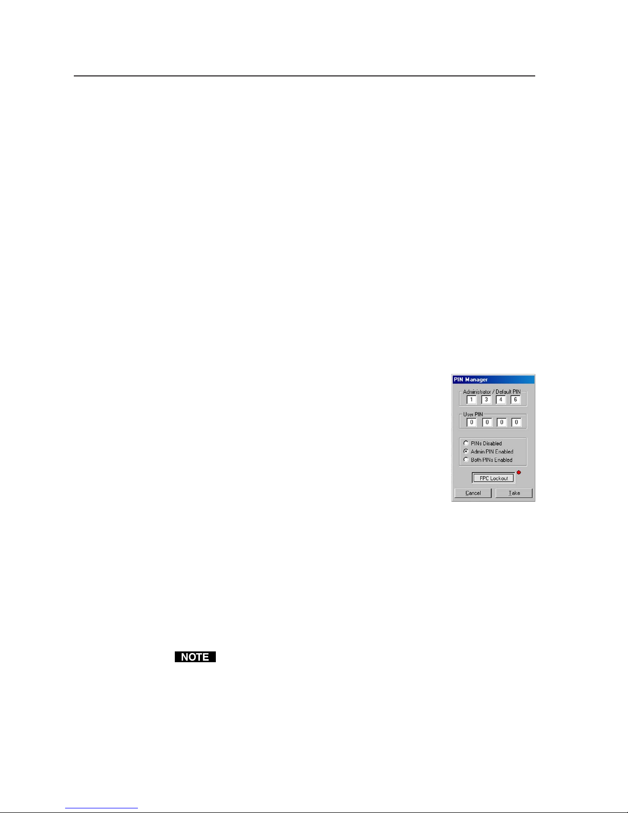
Software- and Web Page-based Setup and Control, cont’d
• The Hardware Status section reflects the voltages and temperatures detected
inside the MLC.
• The Serial Port Configuration information is a reflection of the settings selected
on the RS-232/IR Config. tab of the configuration software and also of the
factory-set protocol used by the controller’s configuration ports.
• Projector lamp hours are a reflection of time elapsed since the lamp was
changed as determined by the driver scripts associated with the MLC’s
projector control port.
Setting and enabling PINs for front panel lockout (executive mode)
To prevent accidental changes to settings, the MLC features front panel security
lockout (executive) modes for disabling access to controls. When panel lockout is
enabled, the user cannot operate buttons or volume knobs on the MLC’s front
panel, an IR 402 remote control, SCPs control pad, or control modules. Functions
and adjustments can still be made only via the software or SIS commands via
RS-232, Telnet, or Web browser control. The Simple Instruction Set (SIS
command 3X corresponds to this mode. For details on how to lock and unlock
the front panel via the front panel buttons, see pages 3-7 and 3-8.
Before front panel lockout can be enabled via the MLC’s buttons, you must set up
personal identification numbers and enable them.
Set up the PINs and unit access via the PIN Manager feature in the Tools dropdown menu:
™
)
PRELIMINARY
1. Connect cables, power on the MLC and the host
computer, and start the configuration software.
2. Click on the Tools drop-down menu, and select PIN
Manager. A screen like the one shown at right
appears.
3. Click a radio button (Admin PIN Enabled or Both
PINs Enabled) to enable personal identification
number (PIN) use.
4. Set (type in) PINs. One PIN can be assigned for those
with administrator access, and another PIN can be
assigned for users. Each PIN must consist of four digits, each of which is a
number from 1 to 6. By default the Administrator PIN is 1346 and the User
PIN is 0000.
5. Click the Take button and close the PIN Manager.
6. Exit the configuration software, if desired.
When front panel lockout is enabled, if a button is pressed, the button flashes
red, but no change occurs. Nothing—not input switching, projector control,
room control, volume adjustment, or any other knob- or button-executable
function—results from front panel actions when lockout is active. Changes can
still be made via RS-232 or Ethernet control.
If PINs Disabled is selected via the PIN Manager drop-down box in the
configuration software, front panel lockout can’t be enabled/disabled by
anyone (with or without a PIN) via the front panel.
4-12
MLC 226 Series • Software-and Web Page-based Setup and Control
Page 47

Viewing and resetting button-usage statistics
If you want to know how often a particular button on the
MLC is pressed, either physically or virtually (via
configuration software, SIS commands, or event scripts),
select Button Usage Statistics from the Tools drop-down
menu. A window like the one shown at right opens.
The number of presses (real or simulated) is indicated for
each button. Clicking the Reset Stats button will cause all
buttons to indicate 0 presses. Clicking the Update button
refreshes (updates) the displayed numbers of button
presses.
Loading enhanced Web pages
From the factory, the MLC 226 IP comes with a preloaded
Web page with a basic representation of the MLC 226’s
front panel controls and the buttons of any optional
attached control modules. Web pages that show a more
lifelike representation of the MLC’s front panel and of control modules are
included with the configuration software. These pages (over 200 files) can be
uploaded into the MLC if you select Load Enhanced Web Pages from the Tools
menu and follow the on-screen instructions. To see pictures of both the plain
Web page and the enhanced Web page, see page 4-48.
Rebuilding and applying a configuration
In most cases you will not need to rebuild a configuration unless you have
changed the controller’s settings, drivers, or event scripts. If configuration
changes have been made that require rewriting file settings, a button
(
window to let you update the configuration files and store them in the MLC. If
not, you may use the Rebuild & Apply Configuration option in the Tools menu
to write the changes to or otherwise rewrite the configuration file. It takes a
couple of minutes to rewrite the configuration.
) should appear in the lower right of the configuration program
PRELIMINARY
IR learning: creating a customized IR driver file
If you do not find a driver (via the RS-232/IR Config. tab [tab three] of the
configuration software) for the specific device you plan to use, you can create
your own IR driver file.
If you select IR Learning from the Tools menu, the IR Learner utility opens in a
new window. With this tool you can create a driver file of IR commands that can
then be loaded into the driver list and used for port setup and button
configuration in the MLC.
1. Select Learn IR from the Tools menu.
MLC 226 Series • Software-and Web Page-based Setup and Control
Clicking the Build & Apply button or selecting Rebuild & Apply
Configuration option in the Tools menu will also clear any settings in the
email monitoring and Scheduling sections. Remember to re-enter any
scheduling information after using the Build & Apply button or the
Rebuild & Apply Configuration option.
If you are logged into the configuration software as a user instead of as an
administrator, you will not be able to use the IR Learner utility.
4-13
Page 48

Software- and Web Page-based Setup and Control, cont’d
The IR Learner opens as a blank screen like the one shown below.
PRELIMINARY
There should already be an established connection between the MLC and
the PC, and that connection is listed in the toolbar window near the top of
the screen (for example,
and the Connect button (
2. If an active connection is already established between the controller and the
PC, skip to step 4. If not, click on the Device Finder icon (
box that pops up, you can set/select how to connect to the MLC: via an IP
connection (TCP) or via RS-232 (Serial). Then select the specific device or
connection parameters.
• For
IP connection, select the
TCP tab (shown at right),
and either select the MLC
from a list of IP Learning
devices found on the same
network, or enter the IP
address in the Address
field. A password is not
required unless an
administrator password has
already been set for the
MLC.
) is already selected.
or );
). In the dialog
4-14
MLC 226 Series • Software-and Web Page-based Setup and Control
Page 49

• For RS-232 connection, select the Serial tab (shown below), then select
the appropriate protocol for the connection:
38400 baud
•
• 1 stop bit
• no parity
• 8 data bits
• no flow control
A password is not required.
If you have access to the
MLC via a direct RS-232
connection, you are
assumed to have
administrator access
privileges.
3. Select Connect to accept the settings and make the connection to the MLC.
If you chose an IP connection, the IP address is displayed in the connection
information window (
If you selected an RS-232 connection, the protocol is shown in the window
(
Selecting OK instead of Connect accepts the settings but does not make the
connection. To establish a connection from the PC to the MLC after selecting
OK, you’d need to click on the Connect button (
).
).
).
4. Start a new IR driver file
by clicking on the Create
New Driver button (
(as shown at right) or by
selecting New from the
File menu.
)
PRELIMINARY
MLC 226 Series • Software-and Web Page-based Setup and Control
4-15
Page 50

Software- and Web Page-based Setup and Control, cont’d
5. Fill in the information about the driver you are creating.
Use the drop-down menus to
select the type of device for
which IR commands will be
learned and to select the
manufacturer of that device.
Enter the model number/name of the device, and also any comments that
will be useful to you later.
Typical functions associated
with that type of device are
shown in the window to the
left of this information.
PRELIMINARY
6. In the list that appears in the left window, click on a function or functions to
be learned. To select multiple functions from the list, press and hold the
control (Ctrl) key on the keyboard and click on the desired functions. (The
blue arrows (
not been saved to the driver file.)
If the “Other” category is selected from the Type drop-down menu, no list
appears in the left window. To add functions that are not listed in the
window to the left of the driver information, click on the Add New Function
button (
function, double-click on it and enter the function’s new name.
) indicate functions that have not been learned or that have
) to add a blank, customizable function. To rename the new
4-16
MLC 226 Series • Software-and Web Page-based Setup and Control
Page 51

7. Click on the Learn Selected Function icon ( ) located in the IR Learner
program’s toolbar. A learn function dialog box appears, as shown in the
following screen samples, and the function(s) to be learned is (are) listed
within that dialog box.
The example below shows how the screen looks when multiple functions
have been selected.
8. Click on the Learn button to start the IR learning process, and follow the
onscreen instructions. During IR learning, point the device’s remote control
at the IR learning receiver and keep it within about 12" (30 cm) of the port.
See the following examples.
PRELIMINARY
MLC 226 Series • Software-and Web Page-based Setup and Control
4-17
Page 52

Software- and Web Page-based Setup and Control, cont’d
5
6
4
LECTERN
PC
LAPTOP
IR
15 15
1
2
4
5
7
8
0
PC
CONFIG
MLC 226 IP
2"–12"
(4–30 cm)
3
6
9
PRELIMINARY
9. If IR learning was successful, click Accept. If not, click Re-learn.
10. Repeat steps 6 through 9 for each command you want to include in the
driver.
If two or more functions have been selected and the Auto Select Next
Function button is checked, the next function shown in the dialog box is
highlighted (selected) automatically, so you can skip step 6 for the listed
functions.
11. To add additional functions that are not listed in the window to the left of
the driver information, click on the Add New Function button (
) to add a
blank, customizable function. To rename the new function, double-click on
it and enter the function’s new name.
12. To remove an unneeded function, select that function from the list, then
click on the Unlearn Function button (
), which resembles an eraser.
13. Save the IR driver file. Select Save from the File menu or click on the Save
Driver button, which looks likes a floppy disk. Name the file (use a name
that reflects the device’s model name), then click Save. The driver must be
saved in the directory C:\Program Files\Extron\Driver.
14. To create an additional IR driver, repeat steps 4 through 13. If you are
finished with IR learning, close the IR Learner utility program. When the
program
closes, the
following
window
appears:
15. Click Ye s to rebuild the driver list. You must rebuild the driver list before
you can select the new driver in the RS-232/IP Config. page of the
configuration program.
4-18
MLC 226 Series • Software-and Web Page-based Setup and Control
Page 53
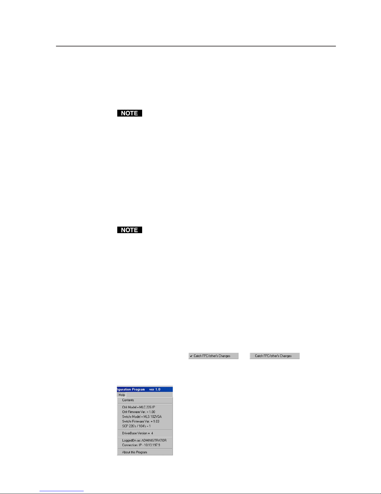
Updating MLC 226 IP firmware
If the need arises, you can replace the MLC 226 IP’s firmware without opening
the unit or changing firmware chips. To check which version of firmware the
controller is using, click on the Help menu. The firmware updating procedure
must be performed using a PC on which the MLC 226/104 Configuration
Software has been installed.
You may wish to save the existing configuration to a file (see page 4-10)
before replacing the firmware.
See appendix B, “Troubleshooting and Firmware Updates”, for instructions on
how to update the controller’s firmware.
Performing a master reset
The master reset function clears all event files; all projector drivers; and the
control module, IR, RS-232, audio, and other settings.
• If you select Master Reset (MLC) from the Tools menu, all settings are replaced
with the factory default settings; and all projector, port, and button
configurations are erased.
• If you select Master Reset (MLC & File System) from the Tools menu, not only
are the configurations erased and the MLC reset to factory defaults, but all the
installed files are erased from the MLC’s memory. This includes event files,
configuration files, and user-created Web pages.
Master reset does not remove any settings on the IP & Email Config. tab. A
connection between the PC and the controller should still exist after
performing a master reset.
Enabling/disabling switcher slaving
An Extron MediaLink Switcher (MLS) can be connected to the MLC to expand
the number of inputs available to the projector/display. If switcher slaving is
enabled and the MLS is connected to the MLC, a representation of the MLS
switcher’s front panel may appear on the Real Time Adjustments tab of this
configuration software, enabling you to make audio and other adjustments.
Reflecting changes made via attached SCPs or control modules
By default the MLC’s front panel, an attached SCP panel, and the configuration
software’s User Mode tab all reflect the same settings and input selections. That
is possible because the “verbose” mode of communication is active: the front
panel, keypad(s), and software (via the PC) automatically notify each other of
changes. If you need to reduce network traffic or perform some types of
troubleshooting, you may wish to turn verbose communication off by deselecting
Catch FPC/other’s Changes (
—> ).
Help menu
To access the Help file, select Contents from the Help menu.
In addition to providing access to onscreen help files,
this menu displays information about the controller
and connected accessories that is useful during
troubleshooting. Among other items, it lists any
connected SCP and/or MLS switcher.
PRELIMINARY
The Help menu
MLC 226 Series • Software-and Web Page-based Setup and Control
4-19
Page 54

Software- and Web Page-based Setup and Control, cont’d
User Mode
The User Mode tab, shown below, includes the most frequently used controls: it
emulates the front panel for basic functions (projector power on/off, relays and
other functions, input selection, volume control). If Extron control modules
(IRCMs, ACMs, RCMs) are connected, they are shown on this tab. If an Extron
MLS switcher is connected, its front panel is
different front panel lockout options appear depending on the switcher model.
not shown on this screen. However,
PRELIMINARY
User Mode tab for an MLC 226 IP and three control modules
(IRCM-DV+, IRCM-VCR, IRCM-DVD), with front panel security lockout
enabled for both the MLC and an MLS 100 Series switcher
User Mode tab for a system with an IP connection, two IRCM-DV+
control modules, a selected relay, and with front panel security
lockout enabled for both the MLC and an MLS 406 Series switcher
4-20
MLC 226 Series • Software-and Web Page-based Setup and Control
Page 55

If logged in as a user rather than an administrator, you are able to select
buttons and change the volume, but not to enable/disable front panel lockout.
See chapter 3 for details on basic front panel functions.
Noteworthy features
Volume Mute — Check this box (beneath the volume control slider bar) to
activate the audio mute (Amt) command.
Relays — Each relay can be individually enabled/disabled (independently of
other buttons) via the buttons along the side of this window.
Front panel security lockout (executive modes) — See chapter 3 for additional
information.
MLC Front Panel Access — Clicking this button locks or unlocks the
MLC’s front panel. When the MLC is locked, the buttons and the
volume control do not respond to user actions. This feature can be
enabled/disabled via this software or SIS command 3X. See chapter 3
for instructions on how to lock and unlock the panel by pressing front
panel buttons.
Changes and selections can be made only via RS-232 or IP communication
with the MLC if executive mode is enabled.
MLS Front Panel Access — If an Extron MediaLink Switcher (MLS) is
connected to and controlled by the MLC, one or more buttons appear
on the User Mode page to reflect the level or levels of front panel
lockout available for that switcher. Refer to the switcher’s manual for
details on what is supported by the installed switcher.
RS-232 or IP connection indication — When the PC and the MLC are connected,
text in the bar at the top of the configuration program window displays the
name of the COM port (Comm1, for example) or the IP address (as shown
in the sample screens on the previous page).
PRELIMINARY
MLC 226 Series • Software-and Web Page-based Setup and Control
4-21
Page 56

Software- and Web Page-based Setup and Control, cont’d
Real-Time Adjustments
The Real-Time Adjustments tab, shown below, allows you to make adjustments
without having to use the front panel controls, and it provides access to settings not
available via the front panel.
PRELIMINARY
A typical Real-Time Adjustments tab
In this part of the program you can:
• Set an MLS switcher’s per-input audio level (see instructions on the next
page).
• Make overall bass and/or treble adjustments for an MLS switcher.
• Adjust overall volume.
• Choose between stereo and mono output for the Preamp output of an MLS
switcher that features an amplifier.
• Select either 4 ohm or 8 ohm speaker load for the optional MLS switcher’s
amplified output, if applicable for the model connected. Wiring must also
correspond to the setting.
• Set the video format: composite video/S-video or component for some switcher
models.
Video output may turn off briefly (for the duration of the RGB delay setting)
while you set the video configuration.
• Set the RGB delay period (for Triple-Action
• Configure miscellaneous options such as display/projector power-up/-down
delay periods, automatic shutoff periods, and special projector or output
settings.
• Reset the MLS switcher’s settings to factory default settings.
If logged in as a user rather than an administrator, you are able to change
overall volume only. Other settings may not be changed by anyone without
administrator privileges.
™
Switching) for an MLS switcher.
4-22
MLC 226 Series • Software-and Web Page-based Setup and Control
Page 57

Noteworthy features
Several of the adjustments in this part of the program correspond to adjustments
that can be made via front panel controls. Below is a brief description of some
settings that are not accessible through the front panel.
Preset Volume Level — If you enable this feature, when the MLC is powered on
or when the display device (projector) is powered on, the output volume are
limited to a percentage of the maximum power output.
Power-up/Power-down Delay — Most projectors require a certain amount of
time during warm-up and cool-down during which they do not accept
commands. Using these slider bars you can specify the amount of time for
the MLC to wait between sending the projector a power-on or power-off
command and when the next action can occur or the next command can be
issued.
Repeat Power-Down — Some projectors (typically models that use IR drivers)
require the power-down command to be sent out again after a short pause
in order to confirm the request to turn off the projector. Enable this feature if
the equipment you are using requires the power-down command to be
repeated.
Send Channel IR/232 as Display Powers Up — This option causes the MLC to
send a command to the projector to switch to its appropriate input at the
same time it powers up.
Lockout I/O select while Display powers up/down — If enabled, this feature
locks input buttons that are part of the switching rotation (set up to trigger
input switching) while the projector warms up or cools down.
Hold Power-down button 2 seconds — To prevent turning the projector off
accidentally, you can enable this feature, which requires the Projector Off
button to be held down continuously for at least two seconds before the
MLC will issue the power-down command.
Minimum Delay between I/O presses — Sometimes pauses are required
between changes from one input to another so that the projector can adjust
to the new incoming sync signal. This feature lets you select a delay
between input changes of from 0 to 5 seconds in one-half second
increments.
PRELIMINARY
MLC 226 Series • Software-and Web Page-based Setup and Control
4-23
Page 58

Software- and Web Page-based Setup and Control, cont’d
RS-232 / IR Config.
In the RS-232 / IR Config. tab, shown below, you select the settings and device
drivers to use for the projector control port and the four IR/Serial output ports.
PRELIMINARY
Sample RS-232 / IR Config. tab
In this part of the program you can:
• Select whether a specific port will output IR signals or RS-232 commands.
• Select the protocol (baud rate, parity, data bits) for the port if used for RS-232
control or let the controller use the default settings in the driver.
• Choose and add a driver (a set of control commands) for the device you want
to control via that port.
If logged in as a user you are not able to make any changes on this page.
Only those logged on with administrator privileges can alter the port
settings.
Port configuration
To set up each port, make selections from left (choice of port, then the port’s
output protocol) to right (driver category and model). When finished setting up
all the ports, you may click on Build & Apply Configuration. Or you may
continue to configure the controller using the Button Config. tab and the IP &
Email Config. tab, then click on Build & Apply Configuration.
See the procedure on the next page. The numbers (
sample screen pictures correspond to the numbered steps of the procedure.
1, 2, 3
, …) shown on the
4-24
MLC 226 Series • Software-and Web Page-based Setup and Control
Page 59

1. Select a port (Projector Control port or one of the IR/Serial ports) to
3
configure. See
1
in the screen sample above.
2. Select IR or RS-232 communication. The Projector Control port can be
configured for IR or RS-232 communication. RS-232 is shown in
2
in the
sample screen above. A list of device categories for available drivers
appears in the right side of the screen.
3. If you selected RS-232 in step 2, set the serial protocol (baud, parity, data
bits) for the selected port; or select Use Default in Driver to let the driver file
establish the protocol. See
above.
PRELIMINARY
4. Select the general type of device (video projector, document camera, VCR,
MLC 226 Series • Software-and Web Page-based Setup and Control
4
etc.) (see
above) for which a driver is needed. A list of devices in that
category appears in the Device Models field.
4-25
Page 60

Software- and Web Page-based Setup and Control, cont’d
5. Choose a specific device from the Device Models list (see 5 above). In this
example, a Barco 6500 is selected from the projector list, so a list of
functions available specifically for that projector driver appears in the
Functions Available in Driver window.
6. Scroll through the list of available functions (see
commands you will need are available in that driver. If not, you may wish
to try a related model’s driver file. You can view the list of driver functions
at this time, but you cannot change the list at this time.
If the selected port is designated for RS-232 communication, you may see a
“View Docs” button below the Device Models
area, as shown at right. If you wish to read more
about the driver, click on the “View Docs” button
to open a PDF of the “IPL T Interface Communication Sheet” for the selected device driver.
7. To accept the selected device driver, click on the Add Port/Device
Definition button (
displays the name of the configured port and the model name for the driver
you selected. The button for the port you selected in step 1 is now green if
the port is configured for RS-232 or red if the port is set for IR control.
8. Repeat steps 1 through 7 to set up the other ports for controlling the devices
connected to them. The screen may look something like this after
configuration:
7
). The Port and Device Models Selected area now
6
) to make sure that the
PRELIMINARY
9. When port configuration is completed, click on the Build & Apply
Configuration button (lower right corner) to store the port settings and
drivers in the MLC, or wait until the buttons are configured (via the Button
Config. tab) to perform the Build & Apply Configuration.
Events are stopped (turned off) when the configuration is built and applied.
Any scheduling that was set up previously is removed. To restart events,
perform a mode 3 reset. See chapter 2 for instructions.
CAUTION
Review the reset modes carefully. Using the wrong reset mode may
result in unintended loss of flash memory programming, port
reassignment, or a controller reboot.
4-26
MLC 226 Series • Software-and Web Page-based Setup and Control
Page 61

Button Config.
The Button Config. tab shows and provides a way to set up all the available
programmable buttons of Extron devices that are part of the system:
• the MLC/SCP buttons (they are the same buttons and execute the same
functions)
• the IR 402 remote control’s buttons
• the buttons of any attached control modules (IRCMs, RCMs, ACMs)
In this part of the program you associate up to a total of six functions with each
button. You can select from driver functions, relay operations, button light
changes, delays between operations, digital output operations, and/or special
user-programmed commands. The options can be assigned in any combination.
Once the buttons are configured, this screen provides a way to check what type
of command or function, if any, is set for each button.
If logged in as a user rather than an administrator, you are not able to make
any changes to button configurations.
Sample Button Config. tab after buttons have been set up
Configuring buttons
This procedure provides a step-by-step look at how to configure one of the
buttons. The same procedure applies to most of the buttons shown on this
screen. Additional options for the function buttons are discussed in
“Configuring function buttons for toggle mode and/or tracking” in this chapter.
Numbers (
the step numbers for this procedure.
1. Click on a button that you wish to configure on the front panel, a control
1, 2, 3
module, or the IR 402. A dialog box appears on screen that allows you to
select up to six separate actions to associate with the selected button.
, …, 7) shown in the sample screen pictures correspond to
PRELIMINARY
MLC 226 Series • Software-and Web Page-based Setup and Control
4-27
Page 62

Software- and Web Page-based Setup and Control, cont’d
This dialog box overlays the device images and obscures them, but you can
click and drag the box to move it around within the configuration program
window to uncover control modules, the remote control, and other items.
PRELIMINARY
2. Select the type of operation to be performed:
• Driver Operations — executes a command from one of the device
drivers selected in the RS-232/IR Config. tab.
• Relays/Internal Operations — causes a specific relay (1-6) to turn on,
turn off, toggle, or pulse; or you can set digital output operations,
configure button lights, or delays between commands.
• User-defined RS-232 Operations — executes an RS-232 command.
These can be SIS commands for the MLC to act on, or they can be
additional commands for the projector or other devices.
3. Select one or both of the When boxes to choose when the action will occur
(during a button press or a button release), as shown in
4. Select an available port and device.
a. If you chose Driver Operation or User-defined RS-232 operation in
step 2, choose the port the command will be sent to. For both options
you can select from the Projector Port, the IR/Serial ports (A, B, C), or
the slave switcher (MLS) control port. For a user-defined operation you
also have the option to select MLC internal operations.
3
, below.
4-28
MLC 226 Series • Software-and Web Page-based Setup and Control
Page 63

b. If you chose Relays/Internal Operations in step 2, select one of the six
relays, digital output, delays, or Control FPC Lites (which affects only
the function button backlights and any input selection button that is
not part of the switching rotation on the controller and optional SCP).
5. Choose the specific function to perform. The available selections depend on
previous selections.
Select a driver function (see
or choose a relay action,
or choose a digital output operation,
5
),
or select an FPC button light action to perform (available for Function
buttons and buttons of nonswitching inputs only),
or set a delay time,
or select user-defined RS-232 operations and enter the command.
PRELIMINARY
MLC 226 Series • Software-and Web Page-based Setup and Control
4-29
Page 64

Software- and Web Page-based Setup and Control, cont’d
For user-defined commands, to enter a hex character string, precede each
byte with a % (percent sign) and do not include spaces. For example,
%30%31%0D%0A. For user-defined internal operations (commands for
the MLC, itself), you can enter the SIS command directly in the function
name area; no percent symbols are needed.
6. Repeat steps 2 through 5 for any other actions to associate with the selected
button. Here’s an example for Projector On button configuration:
PRELIMINARY
And another example for a function/room button:
7. Click on Take Button Config. (see 7) to save the settings for that button. A
colored LED-like dot is now displayed on the picture of the configured
button. The color indicates the primary configuration type (RS-232, IR, or
relay/internal operations):
8. Perform steps 1 through 7 until you have configured all the buttons.
Button configuration is slightly different for the IR 402. The configurations
for the MLC’s front panel Projector On/Off buttons, the three Function
buttons, and the volume up/down functions are automatically applied to the
corresponding buttons on the IR 402, as shown in the following image.
4-30
MLC 226 Series • Software-and Web Page-based Setup and Control
Page 65

Configuring for toggle mode
Toggle mode allows one set of actions to be triggered when a button is pressed/
released and another set of actions to be triggered when the same button is
pressed/released another time.
When toggle mode is off (the Toggle mode box is unchecked), you can set up a
button as shown in the following sample screen.
Up to six operations can be assigned to the button, and each operation can be set
to occur upon the button’s press, the button’s release, or at both press and
release.
PRELIMINARY
MLC 226 Series • Software-and Web Page-based Setup and Control
4-31
Page 66

Software- and Web Page-based Setup and Control, cont’d
When toggle mode is on (the Toggle mode box is checked), the button
configuration area of the screen is divided into two halves. The first (top) three
operations are assigned to the first press-and-release. The second (bottom) three
operations are assigned to the second press-and-release, as shown below.
PRELIMINARY
• Toggle mode allows just three operations per each button press-and-
release.
• In toggle mode, in most cases you can
use
any combination of settings for
when press/release operations will
occur.
If you encounter problems (compiler
errors, for example) while building and
applying the configuration, try setting
all the operations for either press or
release, as shown at right.
Configuring buttons to repeat (resend) commands
You can set up the MLC so that a set of functions/commands associated with a
button is repeated or re-sent at a fixed
interval as long as that button is still
being pressed. To accomplish that,
check the Repeat while held every:
checkbox, then select a repeat interval
from the drop-down menu that appears
to the right of that checkbox.
4-32
MLC 226 Series • Software-and Web Page-based Setup and Control
Page 67

Configuring function and input buttons for tracking
The function and input buttons that are not part of the switching rotation can be
configured the same way the rest of the buttons can, but they also have an
additional option: tracking.
Tracking makes the function button’s light track (follow) the status of a function
(a relay, controller display mute, or audio mute). The button
lights when the selected function is on and goes dark/dim
when the function is off.
For example, if you set function/room button 2 to track (follow) the audio mute
status, the button lights bright amber when the audio is muted (via the software
or a 1Z SIS command), and it is dim amber when the audio is unmuted (via
software or a 0Z command).
The function/room button’s color cannot be changed from amber to anything
else if the tracking mode is enabled.
PRELIMINARY
MLC 226 Series • Software-and Web Page-based Setup and Control
4-33
Page 68

Software- and Web Page-based Setup and Control, cont’d
IP & Email Config.
This tab gives you a way to specify the IP addresses, system time/date,
passwords, and e-mail notification options.
PRELIMINARY
Typical IP & Email Config. tab
Everything on this tab can be configured by an administrator with the exception
of the hardware (MAC) address, which is set by Extron and cannot be changed.
People with user access can see but not change items on the IP & Email
Config. tab. Only those with administrator access may change these settings.
IP addresses, subnet mask, and e-mail addresses follow standard naming and
numbering protocol. The IP network administrator should provide the IP
addresses and subnet mask to be used with this controller.
Extron Name/Descriptor is any name (e.g., Room104MLC226IP,
Lab1234mlc226IP, ConfRoomSystem, LectureHall8-cntrlr, etc.) you want to use
to label this specific MLC controller unit. The default is a combination of the
product name and part of the hardware address. This can be changed to your
choice of alphanumeric characters and hyphens (-).
• Spaces are not permitted within a unit’s name.
• Underscores (_) are not permitted.
• Valid characters are A-Z, a-z, 0-9, and - (hyphen).
• The name cannot start with a number or a hyphen, and it cannot end with a
hyphen.
• Maximum name length is 24 characters.
Local time is in 24-hour format.
The sync time to PC option sets the controller’s time setting to match that of the
computer on which the configuration program is running.
GMT is the time difference in hours between the installation site and Greenwich
Mean Time.
4-34
MLC 226 Series • Software-and Web Page-based Setup and Control
Page 69

Daylight saving time (DST) is a 1-hour offset (supported for the USA only) that
begins on the first Sunday of April at 2 am and ends on the last Sunday of
October. For example, time in California is GMT -8:00 from April to October and
GMT -7:00 from November to March. DST should be turned off in Hawaii,
American Samoa, Guam, Puerto Rico, the Virgin Islands, the eastern time zone
portion of the state of Indiana, and the state of Arizona (excluding the Navajo
Nation).
Passwords are not required to operate the controller. However, you may wish to
limit access to controller setup by establishing an administrator password.
Only people with administrator access privileges are able to change the
settings (other than volume and input switching) and configuration of the
MLC controller. A password must consist of at least 1 and no more than 12
alphanumeric characters, which cannot include spaces.
If no password is set, everyone has administrator level access to the MLC. An
administrator password can be set without requiring a user password. An
administrator password must be established before the user password field is
made accessible.
Each password must consist of 1 to 12 alphanumeric characters without
spaces or symbols.
Passwords are also case sensitive. Also, passwords for the MLC can be as
short as 1 character. However, the MLC’s internal Web pages require a
password of at least 4 characters.
E-mail notification of status changes — The MLC can be configured to issue
notifications via e-mail when the projector has been disconnected or when a
certain number of hours of use has elapsed since the projector’s lamp was
installed/replaced. The lower half of this IP & Email Config. tab allows you to
enter the e-mail addresses of up to eight contacts for this purpose and to specify
which type of notice (projector disconnection or excessive lamp use hours) each
will receive. Follow the procedure below for e-mail configuration.
The e-mail notification settings (checkboxes/notification functions) are not
available via the MLC’s embedded Web pages.
If the projector/display driver selected for the projector port is a
unidirectional RS-232 driver, the Excessive Lamp Hours and Projector
Disconnected checkboxes also are not accessible or visible in the
configuration program. To monitor projector lamp hours and connection
status:
• The projector control port must be configured with a bidirectional driver.
• The projector must be able to report lamp hour status.
• The Projector On/Off buttons must be configured (via tab 4, Button
Config., of the configuration program).
To configure e-mail notification:
PRELIMINARY
1. Ensure that the correct IP address for the network’s e-mail server has been
2. Enter a valid e-mail address in the E-mail Addressee field.
MLC 226 Series • Software-and Web Page-based Setup and Control
entered in the Mail Server IP Address field.
You must click on the Build & Apply Config. button (lower right of the
configuration program window) to accept the current configuration, store the
settings to files, and generate the main event script that the MLC will use to
determine its operation. Ideally this should be done after configuring IP
addresses and entering e-mail addresses but before the e-mail notification
and scheduling options are selected.
4-35
Page 70

Software- and Web Page-based Setup and Control, cont’d
3. In the same row, click on the Projector Disconnected checkbox and/or the
Excessive Lamp-hours checkbox to set which type of notification should be
sent to that e-mail address.
4. If desired, click on Send Test E-mail to send a sample message to that
recipient.
5. Repeat steps 2, 3, and 4 for each additional e-mail address that should receive
a projector disconnection or lamp change reminder notice.
6. Click on the button at the bottom of the Projector Disconnected column to
select either Monitor or Triggered.
Monitor: the controller checks (monitors) projector communications and
issues an e-mail when a change in connection or response status is
detected.
Triggered: projector monitoring is suspended or discontinued.
7. Click on the button at the bottom of the Excessive Lamp-hours column to
select either Monitor or Triggered.
Monitor: the controller keeps track of how much time the projector has been
turned on and issues an e-mail when the elapsed time exceeds the number of
hours entered in the Max. Lamp Hours field to the right of this button.
Triggered: lamp hour tracking is suspended.
During operation, if projector disconnection is detected or designated lamp
hours have been reached, the Monitor button changes from Monitor to
Triggered and the controller issues an e-mail.
8. Enter the maximum hours that the projector can operate before its lamp is
checked or changed in the Max. Lamp Hours field.
9. Click on the Take button to save the settings.
PRELIMINARY
Scheduling and email settings that were set up previously are removed after
building and applying a configuration.
4-36
MLC 226 Series • Software-and Web Page-based Setup and Control
Page 71

Scheduling
The Scheduling tab makes it possible to automatically turn projector power on
and off once on specific days of the week. Scheduling operates as a simple timer
that tells the controller when to send projector on/off commands.
The Scheduling tab during setup
1. Select the Scheduled check box for the Power Display On function.
2. Select the check box(es) next to the desired day(s) of the week to
3. Click on the up/down arrows next to/in the At: box (below the Scheduled
4. Repeat steps 1 through 3 for the Power Display Off function.
5. Click the Take button.
Scheduling cannot be set up if there are pending changes to the
configuration file. You must build and apply the configuration before
setting up scheduling.
automatically turn the projector on.
check box) to select the time of day for projector power-on.
This part of the program uses a 24-hour time scheme. There is no selection for
a.m. and p.m.
PRELIMINARY
MLC 226 Series • Software-and Web Page-based Setup and Control
4-37
Page 72

Software- and Web Page-based Setup and Control, cont’d
File Manager
The File Manager tab displays a list of files stored on the MLC. It also allows
those with administrator access to load additional files into the controller, delete
files, and copy files from the controller to the PC.
PRELIMINARY
The File Manager tab
By clicking on the column headings, you can sort the list by file name, by time
and date, or by file size (length). An arrow next to a column heading indicates
the currently selected sort order. Click on the Update button to get the most upto-date file list. Click on a filename to select that file.
Only an administrator is able to make changes to the files stored on the
MLC. A person logged in as a user can view the list but not access or change
the files.
File types: a key to file names
You must have a basic understanding of the types of files used by this MLC
controller in order to decide what (if anything) to do with them.
___.eir — These are driver files containing infrared commands. There is a
separate ___.eir file for each device the MLC controls via infrared
communication. This is the type of file created during IR learning. Via the
configuration software, these files can be imported and associated with one
of the controller’s IR/Serial ports.
___.eml — E-mail template files have the .eml extension. These files are used to
generate e-mail messages such as those regarding projector disconnection
and excessive projector lamp hours. The first line of the file is the subject.
The rest of the file contains the body of the e-mail. For the MLC 226 IP, these
files are numerically named (1 through 64). For example, 1.eml, 2.eml,
3.eml,... 64.eml.
___.evt — These are event files, the most important files for the functioning of the
MLC. Almost everything the MLC does is coordinated by the scripts in the
4-38
MLC 226 Series • Software-and Web Page-based Setup and Control
Page 73

main event file, 0.evt. The other event files perform device driver functions.
When the Windows-based configuration program creates event files, it
names (numbers) the files according to port associations. For example, the
main event file, 0.evt, contains instructions for the MLC’s internal
operations, while 5.evt is related to IR/Serial output port A.
CAUTION
________.pke — These are packages of Extron-created device drivers from which
event files are derived. These package files are not stored in the MLC, so
you do not see them in the file manager page. However, they are needed by
the PC during setup.
________.s19 — This is an Extron-supplied firmware update file. When the
firmware is replaced, the MLC is also automatically reset to factory default
settings. This file is not displayed on the file manager page. See appendix B
for details on firmware updates. Firmware can’t be updated by loading an
___.s19 file through the file manager.
MLC.cfg — This is a configuration file generated by the Windows-based
configuration program. It is a reference file used by the configuration
program, and its contents are also human-readable.
MLCmain.sc — This is the source code file generated by the Windows-based
configuration program. It is compiled to create the main event file (0.evt),
which directs all the actions and responses of the MLC.
File Manager buttons and when to use them
Delete Selected File(s) — Clicking on this button causes the selected file or files
to be removed from the MLC. This function can be used for removing files
loaded by the user.
CAUTION
Pick File(s) to Load to Server — Select this option only if a new file must be stored
in the MLC and it cannot be added/uploaded via building and applying a
configuration. This option is mainly for uploading user-designed Web
pages into the MLC.
Get Selected File(s) from Server — Clicking on this button copies the selected
file from the MLC to the PC.
Event files should NOT be deleted. They are necessary for the MLC’s
operation. Never delete the main event file (0.evt).
Event files should NOT be deleted. They are necessary for the MLC’s
operation. Never delete the main event file (0.evt).
PRELIMINARY
Using the help program
For information on program features, press the F1 computer key, click on the
Help menu from within the configuration program, or double-click on the Help
icon in the Extron Electronics group or folder.
For explanations of buttons or functions, select the tabs in the help screen to
reach the desired screen. A description and tips on using the program appears
on screen.
MLC 226 Series • Software-and Web Page-based Setup and Control
4-39
Page 74

Software- and Web Page-based Setup and Control, cont’d
Embedded Web Pages
The MLC 226 IP features an embedded Web server, which includes factory set
Web pages. These pages can be replaced with user-designed files, but the default
Web pages provide many basic features for monitoring, configuring, and
controlling the controller via a Web browser. These Web pages are based on and
provide a subset of the features of the Windows-based configuration program. This
section provides an overview of the embedded Web pages. For details on settings,
refer to descriptions in the corresponding section of the “Configuration Software
for Windows” section.
To access the embedded Web pages,
1. Launch a Web browser (Internet Explorer) on the connected PC, and enter
the controller’s IP address in the address field.
2. In the Enter Network Password
dialog box, shown at right, enter
the controller’s IP address or text
of your choice in the User Name
field, type in the administrator
password in the Password field,
and click OK. The MLC 226 IP’s
default Web page appears.
PRELIMINARY
Passwords must contain 1 to 12 alphanumeric characters. Symbols and
spaces are not allowed, and the passwords are case sensitive.
Administrators have access to all of the Web pages and are able to make
changes to settings.
Users can access the System Status and Control: User Mode pages only.
4-40
MLC 226 Series • Software-and Web Page-based Setup and Control
Page 75

Status: System Status
This page combines many elements from the Windows-based configuration
program’s System Status page (from the Tools drop-down menu), the IP & Email
Config. tab, and the RS-232/IR Config. tab. This Web page provides only information
on settings. Changes must be made via the Configuration Web page or via the
configuration software or SIS programming. Personnel who have user access can
view this page but do not have access to configuration pages.
A typical System Status Web page
PRELIMINARY
MLC 226 Series • Software-and Web Page-based Setup and Control
4-41
Page 76
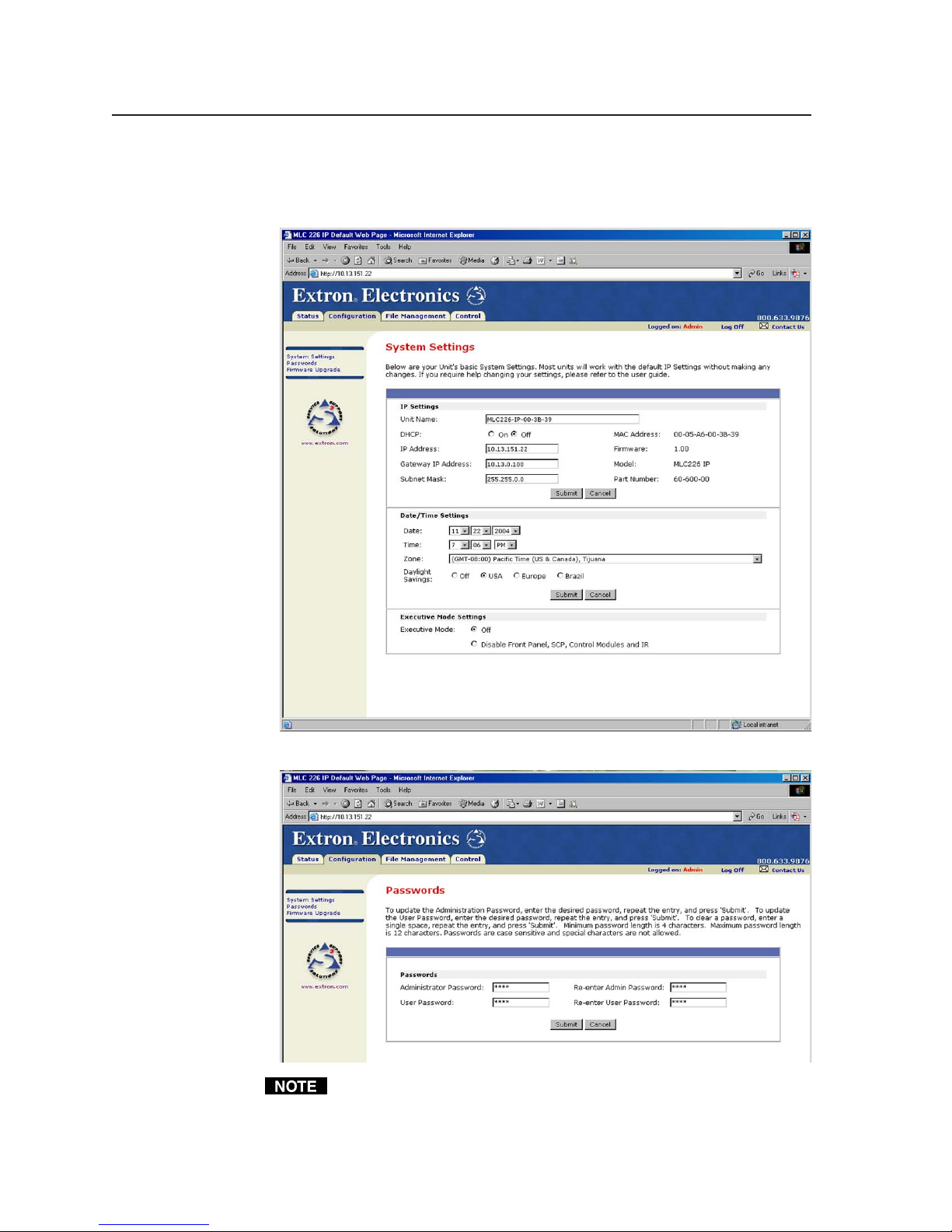
Software- and Web Page-based Setup and Control, cont’d
Configuration
There are four Configuration Web pages, which only administrators can access:
• System Settings for IP, date/time, and executive mode setting changes
PRELIMINARY
• Passwords
Passwords must contain 4 to 12 alphanumeric characters. Symbols and
spaces are not allowed, and the passwords are case sensitive. A minimum of
4 characters are required when creating passwords via the Web pages.
4-42
MLC 226 Series • Software-and Web Page-based Setup and Control
Page 77
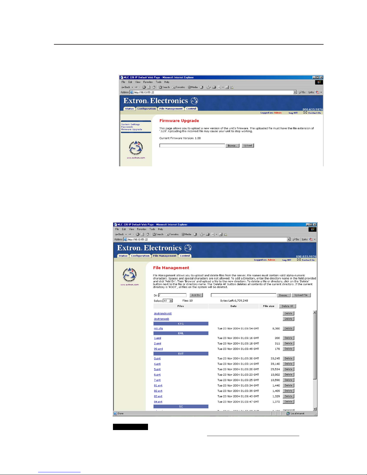
• Firmware Upgrade, which works like the Update Firmware command in the
Windows-based configuration program’s Tools menu
File Management
See page 4-37 for more information and an explanation of file types. This Web
page allows you to sort by file type (see the Filter by: or Select: drop-down box).
Personnel with administrator access can view these pages and make changes.
Those with user-level privileges are not able to see this page.
CAUTION
PRELIMINARY
Event files should NOT be deleted. They are necessary for the
controller’s operation. Never delete the main event file (0.evt).
MLC 226 Series • Software-and Web Page-based Setup and Control
4-43
Page 78

Software- and Web Page-based Setup and Control, cont’d
Control
• User Mode — The first of the Control Web pages is User Mode, which is a
representation of the controller’s front panel buttons, volume control, and
relays, and also of any optional control modules (IRCMs, RCMs, ACMs) that
are part of the system. Clicking on a button on screen emulates a button press
on the corresponding device. This page is accessible to both administrators
and users, but only those with administrator privileges can trigger the relays.
From the factory, the MLC 226 IP comes
with a preloaded Web page with a basic
representation of the MLC 226’s front
panel controls and the buttons of any
optional attached control modules. See the
example at left.
Web pages that show a more lifelike
representation of the MLC’s front panel
and of control modules (as shown below)
are included with the configuration
software. These pages (over 200 files) can
be uploaded into the MLC if you select
Load Enhanced Web Pages from the Tools
menu and follow the on-screen
PRELIMINARY
Typical User Mode page
Enhanced User Mode page
4-44
MLC 226 Series • Software-and Web Page-based Setup and Control
Page 79

instructions.
• IR Drivers — This Web page lists IR driver files only and allows you to select a
file to see and execute the commands stored in them. This page is available
only to those logged in with administrator level access.
An example for a specific IR driver is shown below.
available commands for the device cabled to that port. See the sample screen
shots on the next page.
If you want to execute a command that is available in the driver (whether
associated with an MLC button or not) for a configured device, you can click on
a button or select an option from a pulldown menu to execute that command.
MLC 226 Series • Software-and Web Page-based Setup and Control
PRELIMINARY
• Serial Devices’ Drivers — Once the ports have been
set up in the configuration program, each configured serial
port (projector control port and any IR/Serial control ports)
is listed in this section of the Control page menu.
Click on a port name to bring up a page that shows the
4-45
Page 80

Software- and Web Page-based Setup and Control, cont’d
PRELIMINARY
Example of a page for an RS-232-controlled
teleconferencing unit connected to the
MLC’s IR
/
Serial Out port A
4-46
MLC 226 Series • Software-and Web Page-based Setup and Control
Example of a page for a projector driver
Page 81

Controlling the MLC 226 IP via Global Viewer™
The MLC controller can be used as part of a network of devices based on Extron
IP Link
Windows-based program used for configuring and customizing the Web
browser-based Global Viewer application for each IP Link interface on a network.
Once configured, the Global Viewer allows the user to manage, monitor, and
control connected devices.
At this time the Global Viewer Configurator cannot be used to configure an MLC,
but it can be used to install Global Viewer Web pages on the controller, allowing
an additional way to access basic control functions and controller system
settings via a Web browser. Refer to the Global Viewer Help file for information on
how to use that software.
Two screens for the controller are available via Global Viewer: Control and Info.
™
technology, such as IP Link interfaces. Global Viewer Configurator is a
If the controller has been configured with passwords, the Global Viewer Web
pages are password protected. Although default embedded Web pages are
accessible via the Global Viewer Web pages, nonadministrators (people with
user access) are able to access the Control and Status pages only.
The MLC requires Global Viewer Configurator version 1.5 or higher.
PRELIMINARY
MLC 226 Series • Software-and Web Page-based Setup and Control
4-47
Page 82

Software- and Web Page-based Setup and Control, cont’d
PRELIMINARY
4-48
MLC 226 Series • Software-and Web Page-based Setup and Control
Page 83

MLC 226 MediaLink™ Controllers
Appendix A
A
Reference Material
Specifications
Part Numbers and Accessories
Glossary
Page 84

Reference Material
Specifications
Control/remote — MLC controller host ports
Serial control port ........................ 2 RS-232: 1 rear panel 9-pin female D connector (shared with digital input), 1
front panel 2.5 mm mini stereo jack
Baud rate and protocol ............... 38400, 8 data bits, 1 stop bit, no parity
Serial control pin configurations 9-pin female D connector: 2 = TX, 3 = RX, 5 = GND
Mini stereo jack: tip = TX, ring = RX, sleeve = GND
Ethernet control port .................. 1 RJ-45 female
Ethernet data rate ........................ 10/100Base-T, half/full duplex with autodetect
Ethernet protocol ......................... ARP, DHCP, ICMP (ping), TCP/IP, Telnet, HTTP, SMTP
Ethernet default settings ............. Link speed and duplex level = autodetected
IP address = 192.168.254.254, subnet mask = 255.255.0.0, default gateway =
0.0.0.0
DHCP = off
Secondary control panel (SCP) .. (1) 3.5 mm 5-pole direct insertion captive screw connector (shared with
control module and IR Link port)
IR remote control ........................ IR 402 (optional)
Front panel: 30’ maximum, 40 degrees off axis
Rear panel: 38 kHz, hardwired, modulated
Program control .......................... Extron’s configuration program for Windows
Extron’s Simple Instruction Set (SIS™)
Microsoft
®
Internet Explorer, Telnet
®
PRELIMINARY
Control — relay
Number/type .............................. 6 momentary or latching (configurable via software)
Connectors ................................... (3) 3.5 mm captive screw connectors, 3 pole
Connector configuration ............ Groups A, B, C; each with 1 common and 2 normally open relays (default)
Contact rating .............................. 24 V, 1 A
Control — projector/plasma
Projector control port ................. (1) 3.5 mm direct insertion captive screw connector, 3 pole
Programmable for RS-232 control (±5 V) or TTL level (0 to 5 V) infrared
control up to 1 MHz
Baud rate and protocol (RS-232) 115200 to 300 (9600 default) baud (configurable); 8 (default) or 7 data bits;
1 (default) or 2 stop bits; no parity (default), or even or odd parity
Control — switcher
Switcher control port .................. (1) 3.5 mm direct insertion captive screw connector, 3 pole,
for RS-232 control (±5 V)
Baud rate and protocol ............... 115200 to 300 (9600 default) baud (configurable); 8 (default) or 7 data bits;
1 (default) or 2 stop bits; no parity (default), or even or odd parity
Control — peripheral equipment
IR/serial control ports ................ (3) 3.5 mm direct insertion captive screw connectors, 2 pole
Programmable: RS-232 (±5 V) control, or TTL level (0 to 5 V) infrared
control up to 1 MHz
Baud rate and protocol ............... 115200 to 300 (9600 default) baud (configurable); 8 (default) or 7 data bits;
1 (default) or 2 stop bits; no parity (default), or even or odd parity
IR learning frequencies ............... 30 kHz to 62 kHz
IR learning distance ..................... 2" (5.1 cm) to 12" (30.5 cm) from the front panel
MLC 226 MediaLink™ Controllers • Reference MaterialA-2
Page 85

Digital input control
Number/type .............................. 2 digital
Connector ..................................... 1 rear panel 9-pin female D connector (shared with the MLC controller host
port)
(1) 3.5 mm direct insertion captive screw connector (shared with power
sense port)
Pin configuration ......................... 9-pin female D connector: 1 = digital input, 5 = GND; power sense = digital
in, GND = GND
Input voltage range ..................... 0-12 VDC
Input impedance .......................... 28k ohms
Programmable pullup................. 2k ohms to +3.3 VDC
Threshold low to high ................. >1.2 VDC
Threshold high to low ................. <1.1 VDC
General
External power supply................ 100 VAC to 240 VAC, 50/60 Hz, external, autoswitchable; to 12 VDC, 1 A,
regulated
Power input requirements ......... 12 VDC, 0.5 A
Temperature/humidity .............. Storage: -40 to +158 °F (-40 to +70 °C) / 10% to 90%, noncondensing
Operating: +32 to +122 °F (0 to +50 °C) / 10% to 90%, noncondensing
Rack mount .................................. Yes, with optional rack mounting kits, and also wall- and furniture-
mountable with optional mounting kits
Enclosure type .............................. Metal
Enclosure dimensions
MLC 226 faceplate ........... 4.5" H x 6.4" W x 0.1" D (11.4 cm H x 16.3 cm W x 0.3 cm D) (3 gang)
MLC 226 AAP faceplate .. 4.5" H x 10.1" W x 0.1" D (11.4 cm H x 25.7 cm W x 0.3 cm D) (5 gang)
Device ................................ 2.75" H x 5.3" W x 2.0" D (7.0 cm H x 13.5 cm W x 5.9 cm D)
(fits some 3 gang boxes)
(Depth excludes knob and buttons.)
Product weight............................. 1.9 lbs (0.9 kg)
Shipping weight ........................... 6 lbs (3 kg)
Vibration ....................................... ISTA 1A in carton (International Safe Transit Association)
Listings .......................................... UL, CUL
Compliances ................................. CE, FCC Class A, VCCI, AS/NZS, ICES
MTBF ............................................. 30,000 hours
Warranty....................................... 3 years parts and labor
PRELIMINARY
All nominal levels are at ±10%
Specifications are subject to change without notice.
A-3MLC 226 MediaLink™ Controllers • Reference Material
Page 86

Reference Material, cont’d
Part Numbers and Accessories
Included parts
These items are included in each order for an MLC 226:
Included parts Replacement
MLC 226 IP (controller only) 60-600-00
or
MLC 226 IP (black, white, RAL9010 white) 60-600-02, -03, -05
or
MLC 226 IP AAP (black, white, RAL9010 white) 60-600-12, -13, -15
or
MLC 226 IP L (black, white, RAL9010 white) 60-600-32, -33, -35
12 VDC, 1 amp external power supply
Button labels (text) 33-954-01
Button labels (symbols/icons/pictures) 33-955-01
Tweeker (small screwdriver)
User’s manual
MediaLink International Faceplate Labels
(black, white, RAL9010 white) 33-1167-02, -03, -05
6' CAT 5 crossover patch cable
Mud ring/mounting bracket 70-086-0x
part number
PRELIMINARY
Accessories
These items can be ordered separately:
Adapters, power supplies, labels Part number
9-pin D to 2.5 mm stereo mini TRS RS-232 cable (3') 70-335-01
P/S 100 power supply 60-357-01
12 VDC, 1 amp external power supply 70-055-01
Button labels (International/multilingual text) 33-956-01
Button cap and diffuser kit
Faceplates and frames Part number
UCM 10x8 (black, white) 70-341-02, -03
UCM RAAP (black, white) 70-344-02, -03
MLM-WB+ (black, white) 60-458-02, -03
MLM 226 7GWP
MLM 226 EC AAP (RAL9010 white) 70-343-10
MLM 226 LAAP (black, white) 70-343-02, -03
MLM 226 EC (RAL9010 white) 70-342-10
(set of 3 button cap assemblies) 70-352-01
(black, white, RAL9010 white) 70-340-02, -03, -05
MLC 226 MediaLink™ Controllers • Reference MaterialA-4
Page 87

Electrical boxes and mud rings Part number
EWB-3Gang three gang external wall box 60-454-0x
EWB-5Gang five gang external wall box 60-456-0x
EWB-10x8 external wall box 60-457-0x
SMB-3Gang three gang surface mount box (black) 60-641-02
SMB-5Gang five gang surface mount box (black) 60-643-02
SMB-7Gang seven gang surface mount box (black) 60-645-02
Three gang mounting bracket/mud ring (black) 70-086-12
Five gang mounting bracket/mud ring (black) 70-086-14
Control accessories Part number
IR Emitter 70-283-01
IR Emitter (dual) 70-283-02
IR Broadcaster 60-272-01
Current/display power sensor 60-271-01
IR Link IR signal repeater
(gray, black, white, RAL9010 white) 60-404-01, -02, -03, -05
IR 402 remote control (1) 70-207-01
SCP 226 (black, white, RAL9010 white) 60-671-01, -02, -03, -05
SCP 226 AAP (black, white, RAL9010 white) 60-671-12, -13, -15
SCP 226L (black, white, RAL9010 white) 60-671-32, -33, -35
MLA-VC10 volume controller 60-502-01
IRCM-VCR
(gray, black, white, RAL9010 white) 70-148-01, -02, -03, -05
IRCM-DVD
(gray, black, white, RAL9010 white) 70-149-01, -02, -03, -05
IRCM-DVD+
(gray, black, white, RAL9010 white) 70-179-01, -02, -03, -05
IRCM-Tape
(gray, black, white, RAL9010 white) 70-180-01, -02, -03, -05
IRCM-DV+
(gray, black, white, RAL9010 white) 70-220-01, -02, -03, -05
RCM-SC
(gray, black, white, RAL9010 white) 70-183-01, -02, -03, -05
RCM-SCLT
(gray, black, white, RAL9010 white) 70-184-01, -02, -03, -05
ACM-Tone
(gray, black, white, RAL9010 white) 70-181-01, -02, -03, -05
ACM-Level
(gray, black, white, RAL9010 white) 70-182-01, -02, -03, -05
PRELIMINARY
A-5MLC 226 MediaLink™ Controllers • Reference Material
Page 88

Reference Material, cont’d
Switchers Part number
MLS 100 A 60-497-01
MLS 103 V 60-497-02
MLS 103 SV 60-497-03
MLS 102 VGA 60-497-04
MLS 304MA, MLS 304SA 60-550-01, -02
MLS 406, MLS 406MA, MLS 406SA 60-560-01, -02, -03
MLS 506, MLS 506MA, MLS 506SA 60-386-02, -03, -04
Cables
These cables can be used for the RS-232 control connection between the MLC and
a projector:
Projector control cable Part number
UC 50' (15 m), UC 100' (30 m), or UC 200' (61 m)
universal projector control cable 26-518-01, -02, -03
PRELIMINARY
This cable is recommended for connecting an MLC to an Extron MediaLink
Switcher and/or to an SCP control pad, an IR Link, or control modules such as
IRCM and RCMs:
Comm-link cable Part number
50 feet/15.2 meters long 26-461-01
100 feet/30.5 meters long 26-461-02
200 feet/61 meters long 26-461-03
400 feet/122 meters long 26-461-04
Bulk 500 feet/152.4 meters long 22-119-02
Bulk 1000 feet/304.8 meters long 22-119-03
MLC 226 MediaLink™ Controllers • Reference MaterialA-6
Page 89

Glossary
10/100Base-T is Ethernet which uses unshielded twisted pair (UTP - Cat 5, etc.)
cable, where the amount of data transmitted between two points in a given
amount of time is equal to either 10 Mbps or 100 Mbps.
Address Resolution Protocol (ARP) is a protocol which assigns an IP address to a
device based on the device’s MAC or physical machine address.
Custom Web page is any file that can be loaded into an MLC 226 IP and served by
the switcher’s internal Web server. The Web page provides a way to control
the switcher and other devices attached to it without use of the software.
This is true with or without an accompanying event script. Any number and
size of graphics can be used, but if they are too large to fit in the MLC 226 IP’s
nonvolatile memory, you can create Web pages so that they can be served
from another Web server. If you install Microsoft Internet Information
Services (IIS) on your desktop, you can serve any page on its hard disk. The
MLC 226 IP functions like a little computer with a Web server—you can use it
for various Web-based tasks.
DHCP is the Dynamic Host Configuration Protocol (DHCP), a standardized
communications protocol that enables network administrators to locally and
automatically manage the assignment of IP addresses in an organization’s
network.
Driver is a package of commands that generates or is the event script that controls
devices.
Ethernet is a network protocol that uses MAC addresses instead of IP addresses to
exchange data between computers. Using ARP (see above) with TCP/IP
support, Ethernet devices can be connected to the Internet. An Ethernet LAN
typically uses unshielded twisted pair (UTP) wires. Ethernet systems
currently provide transmission speeds of 10 Mbps or 100 Mbps.
Event script is a program that runs on a MLC 226 IP and issues queries and
commands to the attached devices. Event scripts are written in the “Extron
C” language (.sc), and compiled into an event script (.evt). The Windowsbased MLC 226 IP control program performs this compilation. The compiled
result (.evt) is loaded onto the MLC 226 IP. The Extron C language is similar
to ANSI C, with some differences. As long as event scripts are turned on,
event scripts run continuously on the box.
HTTP is an acronym for the HyperText Transfer Protocol (HTTP), a Web protocol
based on TCP/IP, that is used to fetch HyperText objects from remote Web
pages.
IP (Internet Protocol) is the protocol or standard used to send information from
one computer to another on the Internet.
IP address is a unique, 32-bit, binary number (12 digit decimal number,
xxx.xxx.xxx.xxx) that identifies each device or device port (an information
sender and/or receiver) that is connected to a LAN, WAN, or the Internet. IP
addresses can be static (see static IP) or dynamic (see DHCP).
IP net mask/subnet mask is a 32-bit binary number (12 digit decimal number,
xxx.xxx.xxx.xxx) used on subnets (smaller, local networks) to help routers
determine which network traffic gets routed internally (within the
subnetwork) to local computers and which network traffic goes out to the rest
of the network or the Internet.
Media Access Control (MAC) Address is a unique hardware number given to
devices that connect to a network such as the Internet. When your computer
or networking device (router, hub, interface, etc.) is connected to a LAN or
PRELIMINARY
A-7MLC 226 MediaLink™ Controllers • Reference Material
Page 90

PRELIMINARY
Reference Material, cont’d
the Internet, a table (see ARP) relates the device’s IP address to its
corresponding physical (MAC) address on the LAN.
Pass-through allows control systems to work with the switcher and provides a link
between two ports.
Ping is a utility/diagnostic tool that tests network connections. It is used to
determine if the host has an operating connection and is able to exchange
information with another host. The term (ping) is a reference to submarine
sonar, which sends out a signal and waits to hear it echo (“ping”) back from a
submerged object, much like how the ping utility functions in a network.
Port number is a preassigned address within a server that provides a direct route
from the application to the transport layer or from the transport layer to the
application of a TCP/IP system.
Static IP refers to an IP address that has been specifically (instead of dynamically—
see DHCP above) assigned to a device or system in a network configuration.
This type of address requires manual configuration of the actual network
device or system and can only be changed manually or by enabling DHCP.
Subnet See: subnetwork.
Subnet address The portion of an IP address that is specifically identified by the
subnet mask as the subnetwork.
Subnet mask A 32-bit address mask used in IP to identify the bits of an IP address
that are used for the subnet address. Using a mask, the router does not need
to examine all 32 bits, only those selected by the mask.
Subnetwork is a network that is part of a larger IP network and is identified by a
subnet address. Networks can be segmented into subnetworks to provide a
hierarchical, multilevel routing structure.
TCP (Transmission Control Protocol) is a connection-oriented protocol defined at
the Transport layer of the OSI reference model. It provides reliable delivery
of data.
TCP/IP (Transmission Control Protocol/Internet Protocol) is the communication
protocol (language) of the Internet. Computers and devices with direct
access to the Internet are provided with a copy of the TCP/IP program to
allow them to send and receive information in an understandable form.
Telnet is a standard terminal emulation utility/protocol that allows a computer to
communicate with a remote user/client. A user who wishes to access a
remote system initiates a Telnet session using the address of the remote client.
The user may be prompted to provide a user name and password if the client
is set up to require them. Telnet enables users to log in on remote networks
and use those resources as if they were locally connected.
MLC 226 MediaLink™ Controllers • Reference MaterialA-8
Page 91

FCC Class A Notice
Note: This equipment has been tested and found to comply with the limits for a Class A digital
device, pursuant to part 15 of the FCC Rules. These limits are designed to provide reasonable
protection against harmful interference when the equipment is operated in a commercial
environment. This equipment generates, uses and can radiate radio frequency energy and, if not
installed and used in accordance with the instruction manual, may cause harmful interference to
radio communications. Operation of this equipment in a residential area is likely to cause harmful
interference, in which case the user will be required to correct the interference at his own expense.
Note: This unit was tested with shielded cables on the peripheral devices. Shielded cables must be
used with the unit to ensure compliance.
Extron’s Warranty
Extron Electronics warrants this product against defects in materials and workmanship for a period
of three years from the date of purchase. In the event of malfunction during the warranty period
attributable directly to faulty workmanship and/or materials, Extron Electronics will, at its option,
repair or replace said products or components, to whatever extent it shall deem necessary to restore
said product to proper operating condition, provided that it is returned within the warranty period,
with proof of purchase and description of malfunction to:
USA, Canada, South America, Europe, Africa, and the Middle East:
and Central America:
Extron Electronics Beeldschermweg 6C
1001 East Ball Road 3821 AH Amersfoort
Anaheim, CA 92805, USA The Netherlands
Extron Electronics, Europe
Asia: Japan:
Extron Electronics, Japan
Extron Electronics, Asia Daisan DMJ Bldg. 6F,
135 Joo Seng Road, #04-01 3-9-1 Kudan Minami
PM Industrial Bldg. Chiyoda-ku, Tokyo 102-0074
Singapore 368363 Japan
This Limited Warranty does not apply if the fault has been caused by misuse, improper handling
care, electrical or mechanical abuse, abnormal operating conditions or non-Extron authorized
modification to the product.
If it has been determined that the product is defective, please call Extron and ask for an Applications
Engineer at (714) 491-1500 (USA), 31.33.453.4040 (Europe), 65.6383.4400 (Asia), or 81.3.3511.7655 (Japan)
to receive an RA# (Return Authorization number). This will begin the repair process as quickly as
possible.
Units must be returned insured, with shipping charges prepaid. If not insured, you assume the risk
of loss or damage during shipment. Returned units must include the serial number and a
description of the problem, as well as the name of the person to contact in case there are any
questions.
Extron Electronics makes no further warranties either expressed or implied with respect to the
product and its quality, performance, merchantability, or fitness for any particular use. In no event
will Extron Electronics be liable for direct, indirect, or consequential damages resulting from any
defect in this product even if Extron Electronics has been advised of such damage.
Please note that laws vary from state to state and country to country, and that some provisions of
this warranty may not apply to you.
Page 92

Extron Electronics, USA
1230 South Lewis Street
Anaheim, CA 92805
USA
www.extron.com
714.491.1500
Fax 714.491.1517
Extron Electronics, Europe
Beeldschermweg 6C
3821 AH Amersfoort
The Netherlands
+31.33.453.4040
Fax +31.33.453.4050
Extron Electronics, Asia Extron Electronics, Japan
135 Joo Seng Road, #04-01
PM Industrial Building
Singapore 368363 Chiyoda-ku, Tokyo 102-0074 Japan
+65.6383.4400 +81.3.3511.7655
Fax +65.6383.4664 Fax +81.3.3511.7656
© 2004 Extron Electronics. All rights reserved.
Daisan DMJ Building 6F
3-9-1 Kudan Minami
 Loading...