

Page 1

Installation Manual
ON
DISPLAY
VOLUME
OFF
PIC
MUTE
AUTO
IMAGE
VCR
DOC
CAM
DVD
3
2
1
5
4
6
PC
LAPTOP
IR
CONFIG
Left Side
MLC 226 IP
Right Side
Front
INTERCOM
R
AUDIO
OUT
HOST
CONTROL
1=D INPUT I/O
2=Tx 3=Rx 5=GND
38400, N, 8, 1
PRESS TAB WITH
TWEEKER TO REMOVE
LAN
Rear
1 2
Rx
Tx/IR
GROUND
A B C D E
GROUND
GROUND
+12V OUT
PWR SNS
+12V OUT
CONT MOD
A B C D E
DISPLAY
RS-232/IR RS-232 12V
CM/IR/SCP
(rotated 180 degrees)
Bottom
IR IN
SCP COM
COMMON
A
NORMALLY OPEN
3 4B5 6
COMMON
RELAYS
COMMON
CA BC
Tx/IR
GROUND
IR/SERIAL OUT
Tx
Rx
Tx/IR
Tx/IR
AB
+12V IN
GROUND
GROUND
GROUND
GROUND
MLS PWR
MLC 226 IP Series
MediaLink™ Controllers
68-955-01 Rev. B
02 07
Page 2

Precautions
Safety Instructions • English
This symbol is intended to alert the user of important operating and maintenance
(servicing) instructions in the literature provided with the equipment.
This symbol is intended to alert the user of the presence of uninsulated dangerous
voltage within the product’s enclosure that may present a risk of electric shock.
Caution
Read Instructions • Read and understand all safety and operating instructions before using the equipment.
Retain Instructions • The safety instructions should be kept for future reference.
Follow Warnings • Follow all warnings and instructions marked on the equipment or in the user
information.
Avoid Attachments • Do not use tools or attachments that are not recommended by the equipment
manufacturer because they may be hazardous.
Consignes de Sécurité • Français
Ce symbole sert à avertir l’utilisateur que la documentation fournie avec le matériel
contient des instructions importantes concernant l’exploitation et la maintenance
(réparation).
Ce symbole sert à avertir l’utilisateur de la présence dans le boîtier de l’appareil
de tensions dangereuses non isolées posant des risques d’électrocution.
Attention
Lire les instructions• Prendre connaissance de toutes les consignes de sécurité et d’exploitation avant
d’utiliser le matériel.
Conserver les instructions• Ranger les consignes de sécurité afi n de pouvoir les consulter à l’avenir.
Respecter les avertissements • Observer tous les avertissements et consignes marqués sur le matériel ou
présentés dans la documentation utilisateur.
Eviter les pièces de fi xation • Ne pas utiliser de pièces de fi xation ni d’outils non recommandés par le
fabricant du matériel car cela risquerait de poser certains dangers.
Sicherheitsanleitungen • Deutsch
Dieses Symbol soll dem Benutzer in der im Lieferumfang enthaltenen
Dokumentation besonders wichtige Hinweise zur Bedienung und Wartung
(Instandhaltung) geben.
Dieses Symbol soll den Benutzer darauf aufmerksam machen, daß im Inneren des
Gehäuses dieses Produktes gefährliche Spannungen, die nicht isoliert sind und
die einen elektrischen Schock verursachen können, herrschen.
Achtung
Lesen der Anleitungen • Bevor Sie das Gerät zum ersten Mal verwenden, sollten Sie alle Sicherheits-und
Bedienungsanleitungen genau durchlesen und verstehen.
Aufbewahren der Anleitungen • Die Hinweise zur elektrischen Sicherheit des Produktes sollten Sie
aufbewahren, damit Sie im Bedarfsfall darauf zurückgreifen können.
Befolgen der Warnhinweise • Befolgen Sie alle Warnhinweise und Anleitungen auf dem Gerät oder in der
Benutzerdokumentation.
Keine Zusatzgeräte • Verwenden Sie keine Werkzeuge oder Zusatzgeräte, die nicht ausdrücklich vom
Hersteller empfohlen wurden, da diese eine Gefahrenquelle darstellen können.
Warning
Power sources • This equipment should be operated only from the power source indicated on the product. This
equipment is intended to be used with a main power system with a grounded (neutral) conductor. The
third (grounding) pin is a safety feature, do not attempt to bypass or disable it.
Power disconnection • To remove power from the equipment safely, remove all power cords from the rear of
the equipment, or the desktop power module (if detachable), or from the power source receptacle (wall
plug).
Power cord protection • Power cords should be routed so that they are not likely to be stepped on or pinched by
items placed upon or against them.
Servicing • Refer all servicing to qualifi ed service personnel. There are no user-serviceable parts inside. To
prevent the risk of shock, do not attempt to service this equipment yourself because opening or removing
covers may expose you to dangerous voltage or other hazards.
Slots and openings • If the equipment has slots or holes in the enclosure, these are provided to prevent
overheating of sensitive components inside. These openings must never be blocked by other objects.
Lithium battery • There is a danger of explosion if battery is incorrectly replaced. Replace it only with the
same or equivalent type recommended by the manufacturer. Dispose of used batteries according to the
manufacturer’s instructions.
Avertissement
Alimentations• Ne faire fonctionner ce matériel qu’avec la source d’alimentation indiquée sur l’appareil. Ce
matériel doit être utilisé avec une alimentation principale comportant un fi l de terre (neutre). Le troisième
contact (de mise à la terre) constitue un dispositif de sécurité : n’essayez pas de la contourner ni de la
désactiver.
Déconnexion de l’alimentation• Pour mettre le matériel hors tension sans danger, déconnectez tous les cordons
d’alimentation de l’arrière de l’appareil ou du module d’alimentation de bureau (s’il est amovible) ou
encore de la prise secteur.
Protection du cordon d’alimentation • Acheminer les cordons d’alimentation de manière à ce que personne ne
risque de marcher dessus et à ce qu’ils ne soient pas écrasés ou pincés par des objets.
Réparation-maintenance • Faire exécuter toutes les interventions de réparation-maintenance par un technicien
qualifi é. Aucun des éléments internes ne peut être réparé par l’utilisateur. Afi n d’éviter tout danger
d’électrocution, l’utilisateur ne doit pas essayer de procéder lui-même à ces opérations car l’ouverture ou le
retrait des couvercles risquent de l’exposer à de hautes tensions et autres dangers.
Fentes et orifi ces • Si le boîtier de l’appareil comporte des fentes ou des orifi ces, ceux-ci servent à empêcher
les composants internes sensibles de surchauffer. Ces ouvertures ne doivent jamais être bloquées par des
objets.
Lithium Batterie • Il a danger d’explosion s’ll y a remplacment incorrect de la batterie. Remplacer uniquement
avec une batterie du meme type ou d’un ype equivalent recommande par le constructeur. Mettre au reut les
batteries usagees conformement aux instructions du fabricant.
Vorsicht
Stromquellen • Dieses Gerät sollte nur über die auf dem Produkt angegebene Stromquelle betrieben werden.
Dieses Gerät wurde für eine Verwendung mit einer Hauptstromleitung mit einem geerdeten (neutralen)
Leiter konzipiert. Der dritte Kontakt ist für einen Erdanschluß, und stellt eine Sicherheitsfunktion dar. Diese
sollte nicht umgangen oder außer Betrieb gesetzt werden.
Stromunterbrechung • Um das Gerät auf sichere Weise vom Netz zu trennen, sollten Sie alle Netzkabel
aus der Rückseite des Gerätes, aus der externen Stomversorgung (falls dies möglich ist) oder aus der
Wandsteckdose ziehen.
Schutz des Netzkabels • Netzkabel sollten stets so verlegt werden, daß sie nicht im Weg liegen und niemand
darauf treten kann oder Objekte darauf- oder unmittelbar dagegengestellt werden können.
Wartung • Alle Wartungsmaßnahmen sollten nur von qualifi ziertem Servicepersonal durchgeführt werden.
Die internen Komponenten des Gerätes sind wartungsfrei. Zur Vermeidung eines elektrischen Schocks
versuchen Sie in keinem Fall, dieses Gerät selbst öffnen, da beim Entfernen der Abdeckungen die Gefahr
eines elektrischen Schlags und/oder andere Gefahren bestehen.
Schlitze und Öffnungen • Wenn das Gerät Schlitze oder Löcher im Gehäuse aufweist, dienen diese zur
Vermeidung einer Überhitzung der empfi ndlichen Teile im Inneren. Diese Öffnungen dürfen niemals von
anderen Objekten blockiert werden.
Litium-Batterie • Explosionsgefahr, falls die Batterie nicht richtig ersetzt wird. Ersetzen Sie verbrauchte
Batterien nur durch den gleichen oder einen vergleichbaren Batterietyp, der auch vom Hersteller
empfohlen wird. Entsorgen Sie verbrauchte Batterien bitte gemäß den Herstelleranweisungen.
Instrucciones de seguridad • Español
Este símbolo se utiliza para advertir al usuario sobre instrucciones importantes
de operación y mantenimiento (o cambio de partes) que se desean destacar en el
contenido de la documentación suministrada con los equipos.
Este símbolo se utiliza para advertir al usuario sobre la presencia de elementos con
voltaje peligroso sin protección aislante, que puedan encontrarse dentro de la caja
o alojamiento del producto, y que puedan representar riesgo de electrocución.
Precaucion
Leer las instrucciones • Leer y analizar todas las instrucciones de operación y seguridad, antes de usar el
equipo.
Conservar las instrucciones • Conservar las instrucciones de seguridad para futura consulta.
Obedecer las advertencias • Todas las advertencias e instrucciones marcadas en el equipo o en la
documentación del usuario, deben ser obedecidas.
Evitar el uso de accesorios • No usar herramientas o accesorios que no sean especifi camente recomendados
por el fabricante, ya que podrian implicar riesgos.
ᅝܼ乏ⶹ•Ё᭛
䖭Ͼヺোᦤ ⼎⫼᠋䆹䆒⫼᠋ݠЁ᳝䞡㽕ⱘ᪡ 㓈ᡸ䇈ᯢDŽ
䖭Ͼヺো䄺⫼᠋䆹䆒ᴎݙ᳝ᲈ䴆ⱘ䰽⬉ˈ᳝㾺⬉䰽DŽ
⊼ᛣ
䯙䇏䇈ᯢк• 䑩ㅸỀ䑩嬦嫿⡈⼆枼敆嬼䍇夤ㆁ㙊⫊₩⏍Ề䑩嬵㕏ɿ
ֱᄬ䇈ᯢк• 䑩ㅸⷕ⪙ ⫊₩嬵㕏ᶧḦ⡈⭇㚦Ề䑩ɿ
䙉ᅜ䄺• 䑩ㅸⷕ徶⫉␂⏍䑩ㅸ㉈⊘ᵋ䗅ㆁ㙊⫊ ₩⏍㐎ẝ嬵㕏ɿ
䙓ܡ䗑ࡴ• ᵎ壂Ề䑩嬦␂⋃⒇㯢㙊㋩劑䗅₸ㅗ弾⇡嫿⡈澤Ḧ忀₎⊲斪ɿ
Advertencia
Alimentación eléctrica • Este equipo debe conectarse únicamente a la fuente/tipo de alimentación eléctrica
indicada en el mismo. La alimentación eléctrica de este equipo debe provenir de un sistema de distribución
general con conductor neutro a tierra. La tercera pata (puesta a tierra) es una medida de seguridad, no
puentearia ni eliminaria.
Desconexión de alimentación eléctrica • Para desconectar con seguridad la acometida de alimentación eléctrica
al equipo, desenchufar todos los cables de alimentación en el panel trasero del equipo, o desenchufar el
módulo de alimentación (si fuera independiente), o desenchufar el cable del receptáculo de la pared.
Protección del cables de alimentación • Los cables de alimentación eléctrica se deben instalar en lugares donde
no sean pisados ni apretados por objetos que se puedan apoyar sobre ellos.
Reparaciones/mantenimiento • Solicitar siempre los servicios técnicos de personal califi cado. En el interior no
hay partes a las que el usuario deba acceder. Para evitar riesgo de electrocución, no intentar personalmente
la reparación/mantenimiento de este equipo, ya que al abrir o extraer las tapas puede quedar expuesto a
voltajes peligrosos u otros riesgos.
Ranuras y aberturas • Si el equipo posee ranuras o orifi cios en su caja/alojamiento, es para evitar el
sobrecalientamiento de componentes internos sensibles. Estas aberturas nunca se deben obstruir con otros
objetos.
Batería de litio • Existe riesgo de explosión si esta batería se coloca en la posición incorrecta. Cambiar esta
batería únicamente con el mismo tipo (o su equivalente) recomendado por el fabricante. Desachar las
baterías usadas siguiendo las instrucciones del fabricante.
䄺
⬉⑤• 嬦嫿⡈⌫倾Ề䑩␂ᵋ㝈㕏䗅䑶㷑ɿ嫿⡈⼆枼Ề䑩㙊♱一䗅Ờ䑶䰼丠Ờ䑶ɿ䩭ᵊ㚢一
澠♱ 一澡㕰⫊ ₩ 嫿㓾澤ᵎ 倾ᵎ 䑩ㅗ 崴 弈 ɿ
ᢨᥝ⬉⑤• ᵻ⫊₩♱ḏ嫿⡈㈕㋊䑶㷑澤嬸㈕㋊ㆁ㙊嫿⡈⍏ㅗ㞍暣䑶㷑䗅䑶㷑一澤ㅗḼẖ㋦ⅱⵃ
䑶䰼丠䗅䑶㷑一ɿ
⬉⑤㒓ֱᡸ• ⣦Ⓟⵄ一澤忀₎埬嵪嵐澤ㅗ愎䆪㉥⋌ɿ
㓈ᡸ•ㆁ㙊丵Ἧ⼆枼䑲嫥嬂䗅丵Ἧ⎙弜垍ɿ嫿⡈怩㯢㙊䑩ㅸ⌰Ḧ㘵㊣䗅昷ḷɿᵻ忀₎℻
䋱大䑶⊲斪ᵎ壂儫ⴲ嬖☿㆔⹁嫿⡈䘗⪑丵Ἧ嬦嫿⡈ɿ
䗮亢ᄨ• 㙊嫿⡈㙻⠴ᵋ㙊彛栏 㤾ㅗ⪕澤⫄ḭ㕰䑩㚦敳㪣㙻㒐だ₄ḷ弈䀮ɿᵎ壂䑩Ḽẖᵝ
壀㉢Ẑ彛栏 ⪕ɿ
䫖⬉∴ • ᵎ㪤䞯䗅㘵㊣䑶㮡ṛ㙊䅇㿹䗅⊲斪ɿ⼆枼Ề 䑩ᵏ⋃⫷㋩劑䗅䘹⍍ㅗ䘹弒⛌⌸䗅䑶㮡ɿ
㉊䂨䑠⋃䗅⸻嫯⡅䍇ⷠ⹄䑶㮡ɿ
Page 3

Table of Contents
Chapter One • Introduction ...................................................................................................... 1-1
About the MLC 226 IP Series MediaLink™ Controllers ......................................... 1-2
MLC 226 IP Series features .......................................................................................................1-2
Controlling other devices .........................................................................................................1-2
System Requirements .............................................................................................................. 1-3
Hardware requirements ...........................................................................................................1-3
Software requirements ...........................................................................................................1-3
How the MLC 226 IP Series Controllers Work: MLC Components and
Interactions .................................................................................................................................... 1-4
Chapter Two • Installation ........................................................................................................2-1
UL/Safety Requirements ......................................................................................................... 2-2
Installing or Replacing Button Labels ........................................................................... 2-2
Panels and Cabling .................................................................................................................... 2-3
Host/Confi g port cabling .......................................................................................................... 2-3
Bottom/rear panel and cabling ............................................................................................... 2-5
Projector/display connections .............................................................................................2-5
Additional control connections ..........................................................................................2-6
MLC 226 IP DV+ connections ......................................................................................... 2-9
Power connection .............................................................................................................. 2-12
Intercom connection .........................................................................................................2-13
Side panel cabling and features ........................................................................................... 2-13
Resetting the Unit .................................................................................................................... 2-15
Pinout Guide ............................................................................................................................... 2-16
Mounting the MLC ................................................................................................................... 2-16
Mounting the MLC to an electrical box or mud ring ......................................................... 2-17
Mounting the MLC to a wall or furniture ........................................................................... 2-18
Rack mounting an MLC 226 IP L ........................................................................................... 2-18
UL rack mounting requirements ....................................................................................... 2-19
Mounting the MLC in a Euro Channel ................................................................................. 2-19
Chapter Three • Operation ........................................................................................................ 3-1
Projector Control ........................................................................................................................ 3-2
Front Panel Features and Operation .............................................................................. 3-2
Buttons ....................................................................................................................................... 3-2
Volume control .......................................................................................................................... 3-4
IR signal sensors ......................................................................................................................... 3-5
Confi guration port .................................................................................................................... 3-6
Optional Control Modules and IR 402 Remote Control ...................................... 3-6
PRELIMINARY
MLC 226 IP Series • Table of Contents
i
Page 4

Table of Contents, cont’d
Front Panel Security Lockout (Executive Mode) ..................................................... 3-7
Enabling and disabling front panel lockout via the embedded Web pages and
the front panel .......................................................................................................................... 3-7
Using the Web pages .......................................................................................................... 3-8
Using the front panel .......................................................................................................... 3-9
Preparing the MLC for front panel lockout ........................................................................ 3-10
Setting up and enabling or disabling PINs ....................................................................... 3-10
Scheduling front panel lockouts ....................................................................................... 3-11
Chapter Four • Software-based Confi guration and Control ...........................4-1
Confi guration and Control: an Overview ...................................................................4-2
The Basic Steps: a Guide to this Chapter and Other Resources ..................... 4-2
Confi guring the MLC for Network Communication ............................................. 4-3
Confi guring the MLC for network communication via Global Confi gurator
software ..................................................................................................................................... 4-4
Confi guring the MLC for network communication using the ARP command ................. 4-4
Confi guring the MLC for network communication via a Web browser ...........................4-5
Confi guring the MLC for network communication using SIS commands ......................... 4-6
RS-232 ...................................................................................................................................4-6
Telnet ....................................................................................................................................4-6
Setting up the PC for IP communication with an MLC ........................................................ 4-7
PRELIMINARY
Global Confi gurator Software for Windows® ......................................................... 4-9
Downloading the software and getting started .................................................................. 4-9
PC system requirements ......................................................................................................... 4-10
Using Global Confi gurator: helpful tips .............................................................................. 4-10
Resources and notes .......................................................................................................... 4-10
A brief guide to Global Confi gurator’s tabs .................................................................... 4-11
Advanced Confi guration ..................................................................................................... 4-12
IR learning to create customized IR driver fi les .................................................................. 4-12
Advanced confi guration options in Global Confi gurator ................................................. 4-12
Display power up/power down settings (Power Settings) .............................................. 4-13
Volume settings ................................................................................................................. 4-14
Digital I/O port settings ..................................................................................................... 4-15
Miscellaneous settings ....................................................................................................... 4-15
Confi guring an auxiliary switcher ........................................................................................ 4-16
Setting up passwords ........................................................................................................4-17
Printing a wiring block diagram ........................................................................................... 4-18
Updating fi rmware ................................................................................................................. 4-18
Saving and uploading the confi guration ............................................................................4-18
Controlling the MLC ............................................................................................................... 4-19
Embedded Web pages ............................................................................................................ 4-19
Status ..................................................................................................................................4-20
System Status ...............................................................................................................4-20
Statistics ........................................................................................................................ 4-21
Confi guration .................................................................................................................... 4-22
File Management ............................................................................................................... 4-24
Control ...............................................................................................................................4-26
ii
MLC 226 IP Series • Table of Contents
Page 5

GlobalViewer™ Web Pages .....................................................................................................4-29
Control ...............................................................................................................................4-30
Monitor .............................................................................................................................. 4-31
Schedule ............................................................................................................................. 4-32
Info .....................................................................................................................................4-33
Customizing the MLC’s Control Web Pages ............................................................. 4-34
Chapter Five • SIS™ Programming and Control .........................................................5-1
Host-to-MLC Communications ............................................................................................ 5-2
MLC-initiated messages ............................................................................................................ 5-2
Password information .............................................................................................................. 5-3
Error responses .......................................................................................................................... 5-3
Error response references ........................................................................................................ 5-3
Commands and Responses ................................................................................................... 5-4
Using the command/response tables ..................................................................................... 5-4
Symbol defi nitions .................................................................................................................... 5-5
Command/response table for SIS commands ........................................................................ 5-8
Command/response table for special function SIS commands (accessible via
RS-232 only) ............................................................................................................................. 5-34
Chapter Six • Special Applications ...................................................................................... 6-1
Using Monitoring to Make Functions Track Actual Conditions ..................... 6-2
Prerequisite setup steps ........................................................................................................... 6-2
Setting up the front panel button ......................................................................................... 6-3
Setting up monitoring conditions .......................................................................................... 6-4
Working With Combination Source Devices ..............................................................6-7
Available methods .................................................................................................................... 6-7
Using an IRCM-DV+ control module and one MLC input button for DVD-VCR
control ........................................................................................................................................ 6-7
Controlling Two Display Devices .................................................................................... 6-11
Scheduling Front Panel Lockout Periods ................................................................... 6-14
Sending E-mail by Pressing a Button ........................................................................... 6-14
Working With a Non-MediaLink Extron Switcher ................................................ 6-17
Appendix A • Reference Material ........................................................................................ A-1
Specifi cations .............................................................................................................................. A-2
Part Numbers and Accessories .......................................................................................... A-5
Included parts ........................................................................................................................... A-5
Accessories ................................................................................................................................ A-5
PRELIMINARY
Glossary ........................................................................................................................................... A-7
File Types: a Key to Extron-specifi c File Names ...................................................... A-9
MLC 226 IP Series • Table of Contents
iii
Page 6

Table of Contents, cont’d
Appendix B • Firmware Updates ...........................................................................................B-1
Determining the Firmware Version ................................................................................B-2
Using the Global Confi gurator software ...............................................................................B-2
Using a Web browser ...............................................................................................................B-2
Updating the Main Firmware .............................................................................................B-4
Locating and downloading the fi rmware .............................................................................B-4
Updating fi rmware via the MLC’s embedded Web page .................................................... B-4
Updating fi rmware via Extron Firmware Loader software .................................................B-5
Updating fi rmware via Extron IP Link™ File Manager software .........................................B-7
Resetting the MLC and restoring its confi guration .............................................................B-9
Appendix C • Index ...........................................................................................................................C-1
PRELIMINARY
All trademarks mentioned in this manual are the properties of their respective owners.
68-955-01 B
02 07
iv
MLC 226 IP Series • Table of Contents
Page 7

MLC 226 IP Series
Chapter One
1
Introduction
About the MLC 226 IP Series MediaLink™ Controllers
How the MLC 226 IP Series Controllers Work: MLC Components
and Interactions
PRELIMINARY
Page 8

Introduction
About the MLC 226 IP Series MediaLink™ Controllers
The Extron MLC 226 IP Series MediaLink Controllers are capable of controlling a
projector and various other items such as lights, a projector lift, or a screen motor.
Throughout this manual they are referred to as the MLC 226, MLC, or controller.
All models offer RS-232 and IR-based projector (display) control along with IR or
serial control of other devices (typically A/V input sources); relays for controlling
items such as a projector lift, motorized projection screen, and lights; and RS-232
remote control of an Extron switcher.
MLC 226 IP Series features
All models can be confi gured and controlled via a host computer using RS-232
communication or via IP Link™ Ethernet control. Setup and control can be
accomplished by simple ASCII commands (Simple Instruction Set, SIS™) or via the
included Global Confi gurator™ program. The software offers many more setup
options than does SIS programming.
All models offer front panel controls. The optional IR 402 remote control and
optional SCP 226 Series hard-wired control pads can be used with the MLC, and
they mimic the MLC’s front panel controls. Additionally, the MLC 226 IP DV+
includes an IRCM-DV+ control module (for DVD and VCR control) installed in the
faceplate.
Via Ethernet/IP communication the MLC 226 IP models can make use of
the controller’s embedded Web pages, which include online diagnostics and
monitoring of basic control features. As an integrated part of the MLC 226 IP,
IP Link provides the following advantages:
PRELIMINARY
Global compatibility — The MLC uses standard Ethernet communication
protocols, including ARP, DHCP, ICMP (ping), TCP/IP, Telnet, HTTP, and
SMTP.
Embedded Web page serving — The MLC 226 IP offers up to 7.25 MB of fl ash
memory for storing Extron and user-supplied Web pages, confi guration
settings, and device drivers. Data in fl ash memory is served at a transfer rate
of 6 Mbits per second.
Multi-user support — Two hundred (200) simultaneous connections enable each
IP Link device to support many concurrent users and improve system
throughput by sending information in parallel.
Management ability via Global Confi gurator 2.2 and higher — The included
software and the GlobalViewer Web pages associated with it allow you to
control, monitor, and schedule various functions of products connected to IP
Link products such as the MLC.
E-mail notifi cation — The MLC 226 IP can be set up to send an e-mail when the
projector has been disconnected or the projector’s lamp has been used for a
designated number of hours.
Controlling other devices
The MLC 226 IP Series offers two methods of projector and source device control:
RS-232 or infrared (IR). The MLC can learn IR signals from remote controls to
communicate with sources such as VCRs and DVD players. Users can create their
own device drivers (IR or RS-232) or go to the Extron Web site (www.extron.com) to
obtain device drivers.
1-2
MLC 226 IP Series • Introduction
Page 9

TCP/IP
Network
Help Desk PC
R
O
IT
N
O
M
EL
H
V
IG
H
LE
D
M
E
O
M
RC
W
E
LO
T
IN
Extron
IN
M
D
E
A
IC
F
F
O
PUSH TO TALK
B
4
04
A
L
I 1
IP
3
URITY
SEC
P
L
E
H
2
3
K
S
AP
E
D
6
Projector
Extron
MLS 406SA
MediaLink Switcher
D
V
D
R
Prec
W
/-
is
R
ion C
R
E
inem
C
O
a Progressive
R
D
I
NG
DVD
Projector
Control
S-video
V
0
4
2
-
0
0
1
M
A
.0
1
VCR
z
H
0
-6
0
5
1
.
X
A
RGBHV
R
Y
INPUTS
VIDEO
3
C
2
PU
UT
O
Video
IX
/M
AUX
ADJU
-42dB
+24dB
IO
UD
A
EL
LEV
LINE
ONO
M
UTS
INP
AUDIO
5
6
4
B
TS
UT
G
O
R
O
IT
ON
M
V
H
Document Camera
DVD
2
5
VCR
O
PC
AUT
1
AGE
IM
4
P
TO
P
PROJECTOR
LA
OFF
DOC
MUTE
CAM
G
I
F
ON
N
O
C
IR
VOLUME
Extron
MLC 226 IP AAP
MediaLink Controller
TPUT
U
T
F
E
L
LIFIED O
MP
A
RIGHT
V
2
1
IR
x
R
x
T
C
B
A
2/MLC/IR
S
T
RS-23
3
IO INPU
PREAMP
AUD
PUT 4
L
IN
2
OUT
LINE
L
1
L
ST
R
TO
R
R
PC
IPI 104 AAP
1
226 IP A
MLC
Intercom
Extron
SI 26
Surface-Mount
Speakers
Laptop
w/ Audio
A typical application for an MLC 226 IP MediaLink Controller
System Requirements
The MLC 226 IP and Global Confi gurator have the following hardware and
software requirements.
Hardware requirements
• Intel® Pentium® III 1 GHz processor
• 512 MB of RAM
• 50 MB of available hard disk space
• A network connection with a minimum data transfer rate of 10 Mbps (100 Mbps
is recommended)
Software requirements
• Microsoft® Windows® operating system
• Windows NT service pack 4, or
• Windows 2000 service pack 2, or
• Windows XP service pack 2
• Microsoft Internet Explorer
• Microsoft Windows Script 5.6
C
Do not run Global Confi gurator software on a PC that uses an earlier
version of Windows.
®
6.0 with ActiveX® enabled
PRELIMINARY
MLC 226 IP Series • Introduction
1-3
Page 10

Introduction, cont’d
How the MLC 226 IP Series Controllers Work: MLC Components and Interactions
Unlike the Extron MediaLink Controller (MLC 206 Series), the MLC 226 IP Series
requires and uses event fi les to perform all functions except basic input switching
and volume control. The event fi les defi ne, monitor, and govern how an MLC 226
IP Series controller works. Below is an example diagram of how the MLC interacts
with accessories, event scripts, drivers, ports, and input and output devices.
PC
with
Config.
Program
or
Web
Browser
LAN
Por t
Host
Por t
MLC 226 IP
FPC
Lights
Memory
PRELIMINARY
SCP
SCP
Lights
Control
Modules
IR 402
FPC
2-way
RS-232
1-way
RS-232
IR
Out
Proj.
DVD
VCR
MLC 226 IP
Firmware
MAIN EVENT
(0.evt)
Proj. Driver
(4.evt)
DVD
Driver
(5.evt)
VCR Driver
(2.eir)
Serial
Driver
Serial
Driver
IR
Driver
RS-232
Proj Port
IR/Serial
Port A
IR/Serial
Port B
The MLC can be confi gured completely via the Extron Global Confi gurator
software. Once you have set up how you want it to work (assigned drivers to
ports, confi gured buttons and relays, and set up IP addresses and functions), that
information is saved to a project fi le that is uploaded into the MLC.
The confi guration information is used to create the “main event” (0.evt) script fi le
that defi nes the MLC’s operation. The main event fi le also controls and monitors
ports, optional SCP control pad(s), and changes made at the MLC’s front panel.
Each button on the MLC and on any connected SCPs, control modules (IRCMs,
ACMs, RCMs, CMs, DVCM), or the IR 402 remote control, has two switch numbers
assigned to it: one for the button press, one for release. Scripts are compiled to
generate the main event fi le to monitor any button press or release and to generate
the actions (issuing commands, triggering relays, switching inputs) associated with
the buttons.
1-4
MLC 226 IP Series • Introduction
Page 11

MLC 226 IP Series
Chapter Two
2
Installation
UL/Safety Requirements
Installing or Replacing Button Labels
Panels and Cabling
Resetting the Unit
Pinout Guide
PRELIMINARY
Mounting the MLC
Page 12

Installation
TEXT
Separate the twopiece button here at
the corner.
Pry the two
pieces apart.
Diffuser
Plunger
Base
Button Label
Clear Lens
Notch
UL/Safety Requirements
The Underwriters Laboratories (UL) requirements listed below pertain to the safe
installation and operation of a MediaLink™ Controller (MLC).
1. Do not use the MLC near water or expose it to liquids.
W
2. Clean the MLC only with a dry cloth.
3. Do not install the MLC near any heat source, such as a radiator, heat register,
4. Unplug the MLC during lightning and thunder storms or when it will be
5. For the installation to meet UL requirements and to comply with National
Installing or Replacing Button Labels
For the MLC or the optional SCP control panel, you may wish to customize the
button labels. The labels can be changed at any time. Follow these steps to change
the translucent button labels:
To reduce the risk of fi re or electric shock, do not expose this apparatus to
rain or moisture.
stove, or another apparatus (including amplifi ers) that produces heat.
unused for long periods.
Electrical Code (NEC), the MLC must be installed in a UL approved junction
box. The end user or installer must furnish the junction box; it is not included
with the MLC.
PRELIMINARY
1. Remove the button from the MLC or SCP; use a small,
fl at bladed screwdriver such as an Extron Tweeker
to gently pry a button out from the front panel.
2. Locate the notch in the corner of one
side of the clear button cap.
3. Separate the white backing
(diffuser) from the clear
button cap (lens); insert
the blade of the small
screwdriver into the
corner notch and gently
twist the blade.
4. Save the translucent,
white diffuser, but
remove the text/
label insert from the
transparent button cap.
5. Select one of the button labels from the
printed label sheets included with the device
(MLC or SCP). Remove the label from its backing, if applicable.
6. Insert the button label into the button cap. Check for correct label orientation.
7. Align the white diffuser plate with the cap. The bumps on the diffuser plate
should be aligned (top and bottom) with the notches on the clear button cap.
Firmly snap it into place.
8. Align the tabs on the MLC’s plunger with the notches on the diffuser plate.
Gently but fi rmly press the reassembled button into place in the MLC’s or
SCP’s front panel.
9. Repeat steps 1 through 8 as needed to relabel other buttons.
2-2
MLC 226 IP Series • Installation
Page 13

C
Panels and Cabling
Host/Confi g port cabling
DISPLAY
ON
VOLUME
MLC 226 IP Front Panel
OFF
PIC
MUTE
MUTE
AUTO
IMAGE
VCR
DOC
CAM
AUX
DVD
VIDEO
3
2
1
5
4
LAPTOP
IR
6
PC
CONFIG
MLC 226 IP
2 1
INTERCOM
R
AUDIO
OUT
ML
226 IP Rear Panel
Rear panel Host Control port — For MLC confi guration and control, connect
a
a Windows
®
-based PC or an RS-232 control system to the MLC via this female,
HOST
CONTROL
1=D INPUT I/O
2=Tx 3=Rx 5=GND
38400, N, 8, 1
PRESS TAB WITH
TWEEKER TO REMOVE
LAN
9-pin D connector. This connector also has one pin designated for digital
input/output.
RS-232 protocol:
The pin assignments of this connector are as follows:The pin assignments of this connector are as follows:
• 38400 baud
• 1 stop bit
• no parity
• 8 data bits
• no fl ow control
DB9 Pin Locations
N
Extron recommends confi guring and controlling the MLC via the LAN
51
96
Female
RS-232 function
Pin
RS-232 function
1 Digital I/O Digital input/output
1 Digital I/O Digital input/output
2 Tx Transmit data
2 Tx Transmit data
3 Rx Receive data
3 Rx Receive data
4 — No connection
4 — No connection
5 Gnd Signal ground
5 Gnd Signal ground
6 — No connection
6 — No connection
7 — No connection
7 — No connection
8 — No connection
8 — No connection
9 — No connection
9 — No connection
Description
Description
Pin
connector. Ethernet connections are faster and more reliable.
PRELIMINARY
MLC 226 IP Series • Installation
2-3
Page 14

Installation, cont’d
The front panel 2.5 mm mini stereo connector Confi g port serves the same
RS-232 function as this rear panel port but is independent from it.
N
Both confi guration ports require 38400 baud communication. This is a higher
Digital input/output: pin 1 and the ground pin together act as a digital input/
output port (depending on confi guration). This allows for an additional way
to trigger events or functions (such as triggering relays, issuing commands, or
sending an e-mail) that have been confi gured using GC.
Digital input: when this port is confi gured as a digital input, it is set to
measure two states: high and low. The threshold voltages are as follows: a
voltage below 2.0 VDC is measured as logic low, and a voltage above 2.8 VDC
is measured as logic high. There is also an internal, +5 VDC, selectable, pullup resistor for this circuit.
Digital output — When this port is confi gured as a digital output, it offers
two output states: on and off. When the port is set to an “on” state, (the
circuit is closed), the I/O pin is connected to ground. Each I/O port is capable
of accepting 250 mA, maximum. When the port is set to the “off” state (the
circuit is open), the output pin is fl oating.
speed than many other Extron products use. The Global Confi gurator (GC)
software automatically sets the connection for the appropriate speed. If using
HyperTerminal or a similar application, make sure the PC or control system
connected to these ports is set for 38400 baud.
PRELIMINARY
If the application calls for TTL compatibility, the circuit can be set up to
provide a 2k ohm pull-up resistor to +5 VDC.
Front panel Confi g (host control) port — This 2.5 mm mini stereo jack serves
b
the same RS-232 function as the rear panel Host Control port, but it is easier
to access than the rear port after the MLC has been installed and cabled. The
optional 9-pin D to 2.5 mm stereo mini TRS RS-232 cable (part #70-335-01,
shown below) can be used for this connection. This port has the same
protocol as the rear panel port mentioned above but does not offer digital
input.
6 feet
RS-232 protocol:
• 38400 baud
6 feet
(1.8 m)
(1.8 m)
• 1 stop bit
• no parity
• 8 data bits
• no fl ow control
N
Both confi guration ports require 38400 baud communication. This is a higher
1
1
5
5
6
6
9
9
9-pin D Connection TRS Plug
9-pin D Connection TRS Plug
Pin 2 Computer's RX line Tip
Pin 2 Computer's RX line Tip
Pin 3 Computer's TX line Ring
Pin 3 Computer's TX line Ring
Pin 5 Computer's signal ground Sleeve
Pin 5 Computer's signal ground Sleeve
Part #70-335-01
Part #70-335-01
speed than many other Extron products use. Global Confi gurator software
may automatically set the connection for the appropriate speed. If using
HyperTerminal or a similar application, make sure the PC or control system
connected to these ports is set for 38400 baud.
N
Extron recommends confi guring and controlling the MLC via the LAN
connector. Ethernet connections are faster and more reliable.
Tip
Tip
Ring
Ring
Sleeve (Gnd)
Sleeve (Gnd)
2-4
MLC 226 IP Series • Installation
Page 15

Bottom/rear panel and cabling
MLC 226 IP Rear Panel
MLC 226 IP Rear Panel
INTERCOM
R
HOST
CONTROL
7
AUDIO
OUT
1=D INPUT I/O
2=Tx 3=Rx 5=GND
38400, N, 8, 1
PRESS TAB WITH
TWEEKER TO REMOVE
LAN
5 6 4 1 2 3
1 2
COMMON
A
RELAYS
NORMALLY OPEN
3 4B5 6
COMMON
Tx/IR
COMMON
GROUND
CA BC
IR/SERIAL OUT
Tx/IR
Rx
Tx/IR
GROUND
GROUND
PWR SN S
DISPLAY
RS-232/IR RS-232 12V
GROUND
A B C D E
+12V OUT
+12V OUT
CONT MOD
A B C D E
CM/IR/SCP
IR IN
SCP COM
GROUND
Tx/IR
GROUND
Tx
Rx
AB
GROUND
MLS PWR
GROUND
+12V IN
MLC 226 IP Bottom Panel
Display control (Display RS-232/IR) and display power sensor port
a
CM/IR/SCP port
b
Relay ports (24 V, 1 A)
c
IR/Serial Output ports
d
MLS connector
e
PWR (power) connector
f
Intercom connectors
g
PRELIMINARY
Projector/display connections
Display control (Display RS-232/IR) port (-5 VDC to +5 VDC) —
a
Connect a cable between the projector or display and the left three poles of
this 3.5 mm direct insertion captive screw connector for bidirectional RS-232
control. Alternatively, the Tx/IR and Ground pins can be used for one-way
infrared signal output. From this port, commands from a projector driver or
user-defi ned command strings entered via Global Confi gurator can be sent to
the display device.
Transmit (Tx)
Receive (Rx)
Ground ( )
Bidirectional
Rx
Tx/IR
GROUND
GROUND
PWR SNS
+12V OUT
DISPLAY
RS-232/IR
MLC 226 IP
Bottom Panel
Transmit (Tx)
Receive (Rx)
Ground ( )
Projector
Panel
MLC 226 IP Series • Installation
2-5
Page 16

Installation, cont’d
Connect a cable between the right three poles of the Display port and an
optional Extron Display Power Sensor. The Power Sensor can be used to let
the controller know when the projector/display is on or off. If these pins are
not connected to a Power Sensor, the Pwr Sns and Ground pins can be used
for digital input.
Use the following illustrations as a wiring guide. Wiring varies depending
on the projector/display model. In most cases the drivers are bidirectional,
but sometimes only the transmit (Tx) and ground connections will be needed
for projector/display control. For bidirectional RS-232 communication, the
transmit, ground, and receive pins must be wired at both the MLC and the
projector or display.
To a
projector
or display
To a
projector
or display
Ground ( )
Receive (Rx)
Transmit (Tx)
Ground ( )
Receive (Rx)
Transmit (Tx)
Rx
Tx/IR
GROUND
GROUND
PWR SNS
DISPLAY
RS-232/IR
MLC 226 IP
Bottom Panel
+12V OUT
Power
sense
Ground ( )
+12VDC
Digital Input
Ground ( )
Tip (+12 V)
(signal)
Sleeve ( )
3.5 mm Stereo Plug
Digital Input
Ring
To an Extron
Power Sensor
(60-271-01)
PRELIMINARY
Rx
Tx/IR
DISPLAY
RS-232/IR
MLC 226 IP
N
Maximum distances from the MLC to the device being controlled may vary
Bottom Panel
up to 200 feet (61 m). Factors such as cable gauge, baud rates, environment,
and output levels (from the MLC and the device being controlled) all affect
transmission distance. Distances of about 50 feet (15 m) are typically not a
problem. In some cases the MLC may be capable of transmitting and controlling
a given device via RS-232 up to 250 feet (76 m) away, but the RS-232 response
levels of that device may be too low for the MLC to detect.
Digital input — The power sense (Pwr Sns) pin and the Ground pin together
can act as a digital input port if confi gured that way via Global Confi gurator.
This allows for an additional way to trigger events or functions (such as
triggering relays, issuing commands, or sending an e-mail). When confi gured
as a digital input, this port is in one of two states: 1 (on, high) or 2 (off, low).
Threshold voltages are <2.0 VDC = low, >2.8 VDC = high.
Additional control connections
CM/IR/SCP port — You can connect up to four Extron control modules
b
(IRCMs, ACMs, RCMs, CMs), one Extron infrared signal repeater (IRL 20 or
IR Link), and/or up to two Extron SCP 226 control pads to this port to allow
remote control of the MLC 226 controller or other items. A maximum of seven
devices can be connected to this port.
GROUND
Each projector or display may
N
N
GROUND
PWR SNS
+12V OUT
Each projector or display may
require different wiring. For
require different wiring. For
details, refer to the manual that
details, refer to the manual that
came with the projector/display
came with the projector/display
or the Extron device driver
or the Extron device driver
communication sheet.
communication sheet.
2-6
The SCP 226 replicates the MLC’s front panel controls. The SCP 226 and
the IR signal repeater can receive IR signals from an optional IR 402 remote
control and send them to the controller. Control modules can be used (once
MLC 226 IP Series • Installation
Page 17

the MLC is set up) to control VCRs, DVD players, tape decks, a projector lift,
or screen control. Refer to the appropriate device’s user’s manual.
N
MLC 226 IP
If outside factors such as fl uorescent light interfere with and affect the function
of the MLC, you can disable IR control of the MLC. Using a special function
SIS command (65#), you can turn off the MLC’s ability to receive IR signals
from IR signal repeaters and SCPs.
The control modules, IR signal repeater, and SCPs can be daisy chained, as
shown in the following diagram. Extron Comm-Link (CTL and CTLP) cable
is recommended for these connections. Use the following diagrams as wiring
guides.
IR Link
Maximum =
1 IR Link
SIGNAL
IR LINK
A
+12 VDC
B
Ground
and Drain
D
Modulated IR
(from IR Link)
SCP 226
+12 VDC
A
Ground ( )
B
IRCM, ACM, RCM
IR IN
GROUND
SCP COM
+12V OUT
CONT MOD
A B C D E
CM/ IR/SCP
Bottom
Panel
C
D
SCP communication (IR)
E
200' (61 m) Max.
to Last Device
ON
DISPLAY
VOLUME
OFF
PIC
MUTE
MUTE
AUTO
IMAGE
C
IRCM/ACM/RCM
B
Ground ( )
A
+12 VDC
DVD
VCR
2
1
5
4
DOC
LAPTOP
CAM
IR
CONFIG
DVD & VCR CONTROL
DVD VCR
TITLE MENU
TV/VCR
ENTER
PLAY NEXT/FWD PAUSE STOP
PREV/REW
Tx
SCP 226
Maximum =
2 SCPs
Per System
Maximum =
4 Control
Modules
(4 module
addresses)
3
6
PC
TUNER
PRELIMINARY
Basic connections to an SCP, control module, and IR signal repeater
N
The maximum total distance between the MLC 226 and a connected device is
200’ (61 m).
N
This port provides up to 12 VDC for powering the SCP control pad or other
devices. The automatic current protection circuit for this port limits the draw to
0.5 amperes.
N
SCP control pads or control modules (CM, IRCM, ACM, RCM) used with the MLC
are affected by front panel security lockout (executive mode) status changes.
MLC 226 IP Series • Installation
2-7
Page 18

Installation, cont’d
PRELIMINARY
N
CM/IR/SCP
A B C D E
+12V OUT
GROUND
CONT MOD
IR IN
200' (61 m) Max.
to Last Device
Requirements for setting addresses for IRCM/RCM/ACM/CM control modules
differ depending on how they are connected. If a control module is connected
to the 3-pole connector on an SCP, it can be addressed differently than it would
if connected to the SCP’s 5-pole connector. Refer to the appropriate control
module user’s manual and the SCP 104/226 User’s Manual for instructions
on addressing the control modules.
ACM- Tone
Control Module
MLC 226 IP
Bottom Panel
SCP COM
E
SCP Communication
C
IRCM, ACM, RCM
Ground ( ) & Drain Wire
B
A
+12 VDC
Extron
SCP 226
Address 2
TONE CONTROL
CM-20BB
Control Module
Address 1
DISPLAY
ON
OFF
VOLUME
MAX/
MIN
BASS TREBLE
B
A
PIC
MUTE
AUTO
IMAGE
B
A
CAB
ACM-Tone
Control Module
Address 2
3 Pole
Connector
C
B
A
CM-20BB
Control Module
Address 1
TONE CONTROL
E
DVD
VCR
DOC
CAM
E
3
2
1
5
6
4
PC
LAPTOP
IR
SCP 226
MAX/
BASS TREBLE
MIN
CAB
2-8
NOTE:
2 SCPs
Maximum
Per System
Extron CTLP Cable Color Code:
E
SCP Communication
D
Modulated IR (for IR Link)
C
Control Module Communication
Ground ( ) & Drain Wire
B
A
+12 VDC
Connections to SCP 226 control panels and control modules without an
IR signal repeater
N
The control module(s) connected via an SCP’s 3-pole connector must be the
same models set to the same DIP switch addresses as the control modules
connected directly to the MLC. For example, if an IRCM-VCR and a CM-5BB
are connected to the MLC’s port, each SCP should have an IRCM-VCR and a
CM-5BB (and not other models) connected to its 3-pole connector.
MLC 226 IP Series • Installation
Extron
SCP 226
DISPLAY
ON
VOLUME
PIC
OFF
MUTE
AUTO
IMAGE
= White
= Violet
= Black and Drain Wire
= Red
VCR
DVD
2
1
5
4
DOC
PC
LAPTOP
CAM
IR
3
6
SCP 226
3 Pole Connector
C
B
A
CM-20BB
Control Module
Address 1
TONE CONTROL
BASS TREBLE
ACM-Tone
Control Module
Address 2
CAB
MAX/
MIN
Page 19

MLC 226 IP DV+ connections
The MLC 226 IP DV+ consists of an MLC 226 IP controller and an IRCM-DV+
installed in a high-impact plastic faceplate. The wiring is the same as in the
previous diagram, except the IRCM-DV+ is cabled to the MLC at the factory and
the IRCM-DV+ is the only type of control module that may be connected to each
SCP’s 3-pole connector. See the following diagram.
MLC 226 IP DV+ Rear Panel
INTERCOM
R
AUDIO
OUT
ADBC EADBC E
Factory-wired
MLC - to - IRCM-DV+
Connection
IRCM-DV+
Rear Panel
SCP 226 Rear Panel
J1
1ON2 3 4
ADBC EADBC E
SCP 226 Rear Panel
IRCM-DV+
Rear Panel
ADBC EADBC E
J1
1ON2 3 4
An MLC 226 IP DV+ with SCPs and additional control modules
Relay ports (24 V, 1 A) — These six relays allow control of items such as room
c
lighting, window coverings, and display screens. These contacts may be used
to control any equipment as long as the contact specifi cations of a total of
24 volts at 1 ampere are not exceeded for each port. The pin assignments are
shown in the following picture.
Group B Group CGroup A
HOST
CONTROL
1=D INPUT I/O
2=Tx 3=Rx 5=GND
38400, N, 8, 1
PRESS TAB WIT H
TWEEKER TO REMOVE
LAN
PRELIMINARY
Common Relay 2
1 2
COMMON
A
RELAYS
NORMALLY OPEN
Relay 1
3 4B5 6
COMMON
COMMON
1 2
COMMON
C
A
Common Relay 4
1 2
COMMON
A
RELAYS
NORMALLY OPEN
3 4B5 6
COMMON
COMMON
3 4B5 6
COMMON
RELAYS
NORMALLY OPEN
COMMON
C
Common Relay 6
Relay 3
MLC 226 IP Series • Installation
C
Relay 5
2-9
Page 20

Installation, cont’d
These relays are normally open by default.
They will return to an open state if power is
removed from the controller. They can be
confi gured via SIS commands or the Global
Confi gurator (GC) software to
operate as follows:
• on—relay closes and stays closed
until otherwise instructed
Common
Common
Common
Common
Normally
Normally
Open (5)
Open (5)
All relays
All relays
are
are
normally
normally
open.
open.
Normally
Normally
Open (6)
Open (6)
PRELIMINARY
• off—relay opens and stays open
until otherwise instructed
• toggle—relay changes from open
To / from
To / from
control
control
equipment
equipment
Relay 6
Relay 6
Relay 5
Relay 5
Common
Common
to closed or from closed to
open until otherwise instructed
• pulse—momentary (timed) (press
to turn on, timeout to turn off)
Toggle off
Common
On (Closed)
Common
Relay On
Tur n
Common
Off (Open)
Common
on
Off (Open)
Relay Off
You can also use SIS commands or the GC software to specify pulse duration.
Via the GC software, each relay can be associated with a front panel button or
it can be operated independently.
IR/Serial Output ports — Depending on how the MLC is confi gured,
d
these ports output either infrared signals or unidirectional RS-232 signals
or
On (Closed)
Toggle on
Relay Toggle
Common
On (Closed)
Relay Pulse
Common
Turn off after
a set period
Off (Open)
Common
1 2
1 2
COMMON
COMMON
A
A
Off (Open)
3 4B5 6
3 4B5 6
COMMON
COMMON
RELAYS
RELAYS
for controlling various devices such as VCRs and DVD players. Before it
can be used for controlling a device, each port must be set up via Global
Confi gurator software for either IR or RS-232 communication and associated
with a device driver.
COMMON
COMMON
C
C
2-10
For RS-232 output (-5 VDC to +5 VDC), use the illustration below as a wiring
guide, then wire a serial cable into this captive screw connector.
RS-232 default protocol:
• 9600 baud
• no parity
• 8 data bits
• 1 stop bit
• no fl ow control
N
MLC 226 IP Series • Installation
Maximum distances from the MLC to the device being controlled may vary
up to 200 feet (61 m). Factors such as cable gauge, baud rates, environment,
and output levels (from the MLC and the device being controlled) all affect
transmission distance. Distances of about 50 feet (15 m) are typically not a
problem. In some cases the MLC may be capable of transmitting and controlling
a given device via RS-232 up to 250 feet (76 m) away.
Tx/IR
Tx/IR
Tx/IR
GROUND
GROUND
Tx/IR
Tx/IR
GROUND
GROUND
Tx/IR
GROUND
GROUND
A BC
A BC
IR/SERIAL OUT
IR/SERIAL OUT
Signal (Tx)
Signal (Tx)
Ground
Ground
50'
50'
(15.2 m)
(15.2 m)
(See note.)
(See note.)
To a
To a
Controllable
Controllable
Device
Device
Page 21

For infrared (IR) output (0 to +5 VDC), wire an IR Emitter (2 emitters,
maximum, per port) as shown below for a modulated or demodulated signal
and ground. For specifi c information about wiring more than one IR Emitter
per port or about extending the length of the Emitter wires, refer to the Extron
IR Emitter Installation Guide, part #68-808-01.
N
e
N
If installing two IR Emitters per port, wire them in series, not in parallel.
Alternatively, an Extron IR Broadcaster can be connected here if you need
to send out IR signals to a wider area than is possible for an IR Emitter. The
IR Broadcaster requires a +12 VDC power connection. The +12 V Out and
ground pins of the Display port can be used to provide this power.
Tx/IR
Tx/IR
GROUND
A BC
GROUND
IR/SERIAL OUT
White Striped Wire
Tx/IR
GROUND
Signal (IR)
Ground
100'
(30.5 m)
IR Emitter 1
See chapter 4 for details on how to set up these ports for IR or RS-232 control.
MLS connector — For controlling an optional Extron switcher or other RS-232
controllable device, connect a cable between this 3.5 mm direct insertion
captive screw connector and the RS-232 port of the other device. By default
this port supports Extron MediaLink
™
and PoleVault™ switchers (listed below)
without additional drivers. If it is used to control other products, additional
device drivers may be required.
Supported Extron Devices
The commands issued from this
port are standard Extron SIS
™
commands, and they follow the
typical Extron RS-232 protocol:
• 9600 baud
• 8 data bits
Supported Extron Devices
MLS 304MA
MLS 304MA
MLS 304SA
MLS 304SA
MLS 306
MLS 306
MLS 406
MLS 406
MLS 406MA
MLS 406MA
MLS 406SA
MLS 406SA
MLS 506
MLS 506
MLS 506MA 70 V
MLS 506MA 70 V
MLS 506MA 100 V
MLS 506MA 100 V
MLS 506SA
MLS 506SA
MLS 100 A
MLS 100 A
MLS 102 VGA
MLS 102 VGA
MLS 103 V
MLS 103 V
MLS 103 SV
MLS 103 SV
MLA-VC10
MLA-VC10
PVS 204SA
PVS 204SA
• 1 stop bit
• no parity
PRELIMINARY
If you connect an optional switcher (such as an Extron MLS Series switcher)
to the MLC, you must connect a ground wire between the switcher and the
MLC, as shown in the following diagrams.
MLC 226 IP Series • Installation
2-11
Page 22

Installation, cont’d
p
y
MLC/IR
A B C
MediaLink
Switcher's
rear panel
MLC/IR port
B
A
NOTE If you use cable that
has a drain wire, tie
the drain wire to
ground at both
ends.
Connecting an MLC 226 IP
to a MediaLink Switcher and an external
Power connection
PWR (power) connector — To provide power to the MLC, connect a cable
f
between this port and a 12 VDC, 1 amp (maximum) power supply. See the
following diagram.
N
Power the controller via an external power supply, not from an Extron switcher.
The controller requires a separate 12 VDC power supply.
INPUT 1
VIDEO
Y
100-240V 0.2A 50/60 Hz
C
L LRR LR
.5A MAX
MLS 506MA Rear Panel
NOTE You must connect
a ground wire
between the MLC
and MLS.
Ground ( )
Receive (Rx)
Transmit (Tx)
Transmit (Tx)
Receive (Rx)
B
A
INPUT 2
INPUT 3
INPUT 4
R-Y
VIDEO
R-Y
Y
B-Y
B-Y
C
INPUT 5
VIDEO
R-Y
RH/
RH/
HV
HV
Y
G
G
V
V
B-Y
C
B
B
LR LR LR
Rx
IR IN
Tx/IR
GROUND
A B C D E
SCP COM
GROUND
GROUND
+12V OUT
PWR SNS
+12V OUT
CONT MOD
A B C D E
DISPLAY
RS-232/IR RS-232 12V
CM/IR/SCP
MLC 226 IP
Bottom Panel
MLC's
MLS and
Power
Tx
Rx
A B
MLS PWR
RS-232 12V
GROUND
GROUND
+12V IN
ports
INPUT 6
RGB
RH/
RH/
R-Y
HV
HV
G
G
Y
V
V
B
B
B-Y
AUX/MIXEFFECTS
SENDLRRETURN
LR
LR
1 2
3 4B5 6
COMMON
COMMON
COMMON
CA BC
A
RELAYS
NORMALLY OPEN
Ground ( )
+12 VDC input
Ground all devices.
ower suppl
YUV
Tx/IR
VIDEO
S-VIDEO
Y
C
AUDIO OUT
FIXED VARIABLE
GROUND
IR/SERIAL OUT
Tx/IR
LRLR
GROUND
MONO AMPLIFIED OUTPUT
4 ohm
COMM 8 ohm 70V
MLC/IR RS232
ABC
Rx
Tx/IR
AB
GROUND
MLS PWR
CONTACT CLOSURE
Tx
+12V IN
GROUND
GROUND
External
Powe r Supply
External
Power Supply
(12 VDC, 1 A max.)
PRELIMINARY
Ground ( )
+12 VDC input
Tx
Rx
A B
+12V IN
GROUND
GROUND
MLS PWR
RS-232 12V
Connecting an MLC 226 IP to an external power supply
N
Check the power supply’s
Ground all devices.
polarity before
connecting it
to the MLC.
See the
AA
AA
End View of Power
End View of Power
Supply Output Cord
Supply Output Cord
illustration at
SECTION A–A
right.
Power Supply Output Cord
Power Supply Output Cord
SECTION A–A
External
Power Supply
(12 VDC, 1 A max.)
MLC's
MLC's
Power
Power
Port
Port
+12V IN
+12V IN
GROUND
GROUND
PWR
PWR
12V
12V
0.2”
0.2”
(5 mm)
(5 mm)
MAX.
MAX.
2-12
MLC 226 IP Series • Installation
Page 23

INTERCOM
AUDIO
OUT
IPI 104 AAP, IPI 101 AAP
Rear Panel
MLC 226 IP Series
Rear Panel (left side)
Audio Signal (Tip, +)
Ground (Sleeve, )
To a Speaker, Audio System,
or Paging System
0.2” (5 mm)
MAX.
Connecting an MLC 226 IP to an IP Intercom
INTERCOM
AUDIO
OUT
IPI 104 AAP, IPI 101 AAP
Rear Panel
MLC 226 IP Series
Rear Panel (left side)
Audio Signal (Tip, +)
Ground (Sleeve, )
To a Speaker, Audio System,
or Paging System
0.2” (5 mm)
MAX.
Connecting an MLC 226 IP to an IP Intercom
Intercom connection
Intercom connectors — This port is used for power, control, and voice
g
data communication between the MLC and an optional Extron IP Intercom
( IPI 101 AAP or IPI 104 AAP).
CAT 5, CAT 5e, or CAT 6 cable terminated with RJ-45 connectors into this port on
the MLC. Plug the other end of the cable into the Intercom connector on the IP
Intercom’s rear panel, as shown below.
Plug one end of a standard, straight through,
N
N
Side panel cabling and features
LAN (IP)
Connector
Side View
a
A 12" (30.5 cm) CAT 6 cable is included with each IPI. If you choose to
terminate your own cable, the cable must be no longer than 100’ (30.4 m).
The MLC 226 IP Series controllers that support IPI intercom panels also have
a rear panel, line level, unbalanced audio output port that can be connected
to local, powered speakers or to any audio or paging system. See the wiring
guide in the illustration above.
The volume for this audio output can be adjusted via IP Intercom HelpDesk
software only.
MLC 226 IP
Left Panel
1
LAN (IP) connector and LEDs — An Ethernet connection can be used on
MLC 226 IP
Right Panel
Reset
Button
Reset
LED
an ongoing basis to connect and to control the MLC 226 (and the devices
MLC 226 IP Series • Installation
™
2
2-13
PRELIMINARY
Page 24

Installation, cont’d
Clip Down
1
1&2
3&6
4&5
7&8
23 45678
12345678
RJ-45
Connector
Twisted
Pairs
Straight-through Cable
(for connection to a switch, hub, or router)
End 1 End 2
Pin Wire Color Pin Wire Color
1 white-orange 1 white-orange
2 orange 2 orange
3 white-green 3 white-green
4 blue 4 blue
5 white-blue 5 white-blue
6 green 6 green
7 white-brown 7 white-brown
8 brown 8 brown
Crossover Cable
(for direct connection to a PC)
End 1 End 2
Pin Wire Color Pin Wire Color
1 white-orange 1 white-green
2 orange 2 green
3 white-green 3 white-orange
4 blue 4 blue
5 white-blue 5 white-blue
6 green 6 orange
7 white-brown 7 white-brown
8 brown 8 brown
connected to it) in an Ethernet network. Plug a cable into this RJ-45 socket,
and connect the other end of the cable to a network switch, hub, router, or PC
connected to an Ethernet LAN or the Internet.
• For 10Base-T (10 Mbps) networks, use a Cat 3 or better cable.
• For 100 Base-T (max. 155 Mbps) networks, use a Cat 5 cable.
You will also need to confi gure this port before using it.
Activity LED — This yellow LED blinks to indicate
Link LED — This green LED lights to indicate a good
• Use a
straightthrough cable
for connection
to a switch,
hub, or router.
• Use a crossover
cable (included
with the MLC)
for connection
directly to a
PC. Wire the
connector as
shown in the
tables at right.
network activity.
network connection.
LAN
LAN
Activity
Activity
LED
LED
RJ-45
RJ-45
Por t
Por t
Link
Link
LED
LED
PRELIMINARY
2-14
Confi gure
the settings
for this port
via either SIS commands or
Global Confi gurator. See the
programming sections of this
manual (chapters 4 and 5) for
details.
LAN port defaults:
• MLC’s IP address: 192.168.254.254
MLC 226 IP Series • Installation
• gateway’s IP address: 0.0.0.0
• subnet mask: 255.255.0.0
• DHCP: off
Reset button and LED — Pressing this recessed button causes various IP
b
functions and Ethernet connection settings to be reset to the factory defaults.
See “Resetting the Unit,” in the next section of this manual, for details.
Page 25

Resetting the Unit
There are four reset modes (numbered 1, 3, 4, and 5 for the sake of comparison
with an Extron IPL product) that are available by pressing the Reset button on the
side panel. The Reset button is recessed, so use a pointed stylus, ballpoint pen, or
Extron Tweeker to access it. See the following table for a summary of the modes.
C
Review the reset modes carefully. Using the wrong reset mode may result
in unintended loss of fl ash memory programming, port reassignment, or a
controller reboot.
N
The reset modes listed below close all open IP and Telnet connections and close
all sockets. Also, the following modes are separate functions, not a continuation
from Mode 1 to Mode 5.
Reset Mode Comparison/Summary
Mode
Activation Result Purpose/Notes
1 Hold down the recessed
Reset button while applying
power to the MLC.
After a mode 1 reset
is performed, update the
MLC’s firmware to the
latest version. Do not
operate the MLC firmware
version that results from the
mode 1 reset. If you want to
use the factory default
firmware, you must upload
that version again. See
appendix B, “Firmware
Updates,” for details on
uploading firmware.
3 Hold down the Reset button
for about 3 sec. until the
Reset LED blinks once, then
press Reset momentarily
(<1 sec.) within 1 second.
4 Hold down the Reset button
for about 6 sec. until the
Reset LED has blinked
twice (once at 3 sec., again
at 6 sec.). Then press Rese
momentarily (for <1 sec.)
within 1 second.
5 Hold down the Reset button
for about 9 sec. until the
Reset LED has blinked three
times (once at 3 sec., again
at 6 sec., again at 9 sec.).
Then press Reset
momentarily (for <1 sec.)
within 1 second.
The MLC reverts to the factory default
firmware. Event scripting will not start if
the MLC is powered o
user files and settings (drivers,
adjustments, IP settings, etc.) are
maintained.
If you do not want to update
firmware, or you performed a mode 1 reset
by mistake, cycle power to the MLC to
return to the firmware version that was
running prior to the mode 1 reset. Use the
0Q SIS command to confirm that the
factory default firmware is no longer
running (look for asterisks following the
version number.)
Mode 3 turns events on or off. During
resetting, the Reset LED flashes 2 times if
events are s
stopping.
Mode 4
• Enables ARP capability.
• Sets the IP address back to factory
• Sets the subnet back to factory default.
t
• Sets the default gateway address back
• Sets port mapping back to factory
• Turns DHCP of
• Turns events off.
Reset LED flashes 4 times in quick
succession during reset.
Mode 5 performs a complete reset to
factory defaults (except the firmware).
• Does everything mode 4 does.
• Resets almost all the real time
• Clears driver-port associations and port
• Removes button configurations.
• Resets all IP options.
• Removes scheduling settings.
• Removes/clears all files from switcher.
The Reset LED flashes 4 times in quick
succession during the reset.
tarting, 3 times if events are
default.
to the factory default.
default.
adjustments: all audio settings, limit
initial power up volume, power
up/down delay, auto power down, and
misc. options. This does not affec
optional MLS switcher, however.
configurations (IR/RS-232).
n in this mode. All
f.
t an
Use mode 1
to the factory default
firmware version if
incompatibility issues
arise with
user-loaded firmware.
Mode 3 is useful for
troubleshooting.
Mode 4 enables you
to set IP address
information using
ARP and the MAC
address.
Mode 5 is useful if
you want to start over
with configuration
and uploading, and
also to replace events.
to revert
PRELIMINARY
MLC 226 IP Series • Installation
2-15
Page 26

Installation, cont’d
Pinout Guide
The illustration below summarizes the pin assignments of all of the MLC’s bottom
panel connectors that are covered in detail on pages 2-5 to 2-14.
MLC 226 IP
Bottom Panel
PRELIMINARY
Tx/IR
DISPLAY
RS-232/IR RS-232 12V
GROUND
PWR SN S
GROUND
+12V OUT
A B C D E
A B C D E
CM/IR/SCP
+12V OUT
GROUND
CONT MOD
IR IN
SCP COM
COMMON
A
NORMALLY OPEN
RELAYS
COMMON
B
COMMON
CA BC
Tx/IR
GROUND
IR/SERIAL OUT
Tx/IR
GROUND
Tx/IR
GROUND
AB
MLS PWR
GROUND
GROUND
+12V IN
Mounting the MLC
Once the system has been cabled, confi gured (see chapter 4), and tested, the
controller can be installed in the wall, furniture, equipment rack, or Euro Channel.
Rx
Rx
Tx
1 2
3 4
5 6
Transmit (Tx)
Receive (Rx)
Ground ( )
Power sense
Ground ( )
+12 VDC
+12 VDC
Ground ( )
IRCM, ACM, RCM
Modulated IR (for IR Link or IRL 20)
SCP communication (IR)
Common
Relay 1
Relay 2
Signal (IR)
Ground
Receive (Rx)
Transmit (Tx)
Ground ( )
Ground ( )
+12 VDC input
To a projector or display
To an IR Emitter, IR Broadcaster,
or IR or serial (RS-232) controllable device
To an optional Extron switcher
From an external 12 VDC, 1 A (max.) power supply
To an Extron
Display
Power Sensor
To / from control equipment
(screen control motors, lights, etc.)
OR
To / from optional Extron
control modules, IR Link IR
repeater, or SCP control pads
Digital
input
2-16
1
2
ON
2
1
Mounting screws (4) — Use these to attach the MLC to a wall, furniture, or
a
other mounting surface.
Faceplate attachment screws (4) — Do not remove these screws during or
b
after mounting. They attach the faceplate to the MLC unit. Removing these
screws during or after mounting will cause the MLC to detach, and it may
then fall down into the wall or furniture.
MLC 226 IP Series • Installation
DISPLAY
VOLUME
OFF
PIC
MUTE
LIGHT
OFF
AUTO
IMAGE
VCR
DOC
CAM
1
4
DVD
2
5
LAPTOP PC
IR
CONFIG
3
6
MLC 226 IP
1
2
2
1
Page 27

Mounting the MLC to an electrical box or mud ring
1. With power disconnected at the source, insert the MLC into the wall or
furniture.
2. Mount the MLC to the wall box or mud ring mounting bracket with the
provided machine screws (mounting screws, as shown in the following
illustrations).
N
N
If the MLC (and any accessories such as control modules or an IR Link) is not
mounted to a grounded metal wall box,
• Ground each faceplate directly to an earth ground. Or...
• Tie each faceplate to its circuit board and power supply via a ground pin on
one of the connectors.
Do not tie a product’s faceplate to both a separate earth ground and the circuit
ground (via a connector pin). If you tie a product to two different ground
sources, you may introduce ground
loops or other groundingrelated problems into the
system.
For the installation to
meet UL requirements
and to comply with
National Electrical Code
(NEC), the MLC must
3-gang Wall Box
3-gang Wall Box
be installed in a UL
approved junction box.
The end user or installer
Extron
Extron
MLC 226 IP
MLC 226 IP
must furnish the junction
DVD
box; it is not included
with the MLC.
ON
ON
DVD
VCR
VCR
PC
PC
PIC
PIC
MUTE
MUTE
LAPTOP
LAPTOP
DOC
DOC
OFF
OFF
CAM
CAM
MUTE
MUTE
AUTO
AUTO
Y
Y
IMAGE
IMAGE
LA
LA
P
P
IS
IS
D
D
E
E
M
M
U
U
L
L
O
O
V
V
3
3
6
6
2
2
5
5
1
1
4
4
G
G
CONFI
CONFI
IR
IR
226 IP
226 IP
MLC
MLC
PRELIMINARY
Extron
MR 300
Modular Mud Ring
Rotate locking
arm and insert
into wall
opening.
DVD
VCR
PC
PIC
E
MUT
LAPTOP
DOC
OFF
CAM
ON
AUTO
GE
IMA
PLAY
DIS
UME
VOL
3
6
2
5
1
4
IG
CONF
IR
226 IP
MLC
Mounting the MLC to an electrical box or mud ring
MLC 226 IP Series • Installation
Extron
MLC 226 IP
2-17
Page 28

Installation, cont’d
Mounting the MLC to a wall or furniture
1. If you have an MLC 226 IP Series model other than the MLC 226 IP L, remove
the four faceplate attachment screws and remove the original faceplate, if
applicable.
2. If you have a model other than the MLC 226 IP L, attach the optional lectern
mounting faceplate to the MLC with the screws removed in step 1.
3. With power disconnected at the source, insert the MLC into the wall or
furniture.
4. Fasten the MLC and faceplate directly to the furniture or wall using wood
screws.
N
N
If the MLC (and any accessories such as control modules or an IR Link) is not
For the installation to meet UL requirements and to comply with National
mounted to a grounded metal wall box,
• Ground each faceplate directly to an earth ground. Or...
• Tie each faceplate to its circuit board and power supply via a ground pin on
one of the connectors.
Do not tie a product’s faceplate to both a separate earth ground and the circuit
ground (via a connector pin). If you tie a product to two different ground
sources, you may introduce ground loops or other grounding-related problems
into the system.
Electrical Code (NEC), the MLC must be installed in a UL approved junction
box. The end user or installer must furnish the junction box; it is not included
with the MLC. See “Mounting the MLC to an electrical box or mud ring” on
the previous page.
PRELIMINARY
Rack mounting an MLC 226 IP L
1. Attach an MLC 226 IP L to an optional rack mounting faceplate (UCM-RAAP)
with the provided mounting machine screws and nuts.
2. With power disconnected at the source, fasten the MLC and faceplate to the
rack using the supplied machine screws as shown in the following illustration.
Rack mounting the MLC 226 IP L
Extron
UCM-RAAP
DIS
ON
VOLUME
Extron
Extron
MLC 226 IP L
3
6
DVD
2
5
VCR
PC
PIC
1
PLAY
4
MUTE
LAPTOP
OFF
DOC
L
CAM
G
CONFI
MLC 226 IP
IR
AUTO
IMAGE
2-18
MLC 226 IP Series • Installation
Page 29

UL rack mounting requirements
The following Underwriters Laboratories (UL) requirements pertain to the safe
installation of the MLC in a rack.
1. Elevated operating ambient temperature — If installed in a closed or
multi-unit rack assembly, the operating ambient temperature of the rack
environment may be greater than room ambient temperature. Therefore,
install the MLC in an environment compatible with the maximum ambient
temperature (Tma = +122 °F, +50 °C) specifi ed by Extron.
2. Reduced air fl ow — Install the equipment in a rack so that the amount of air
fl ow required for safe operation of the equipment is not compromised.
3. Mechanical loading — Mount the equipment in the rack so that a hazardous
condition is not achieved due to uneven mechanical loading.
4. Circuit overloading — Connect the equipment to the supply circuit and
consider the effect that circuit overloading might have on overcurrent
protection and supply wiring. Appropriate consideration of equipment
nameplate ratings should be used when addressing this concern.
5. Reliable earthing (grounding) — Maintain reliable grounding of rack-
mounted equipment. Pay particular attention to supply connections other
than direct connections to the branch circuit (e.g. use of power strips).
Mounting the MLC in a Euro Channel
1. Remove the four faceplate attachment screws and remove the original
faceplate, if applicable.
2. Attach the optional MLM 226 EC or MLM 226 AAP EC faceplate to the MLC
with the screws removed in step 1.
3. With power disconnected at the source, insert the MLC into the Euro Channel.
For wider types of Euro Channels, you may need to insert a spacer plate fi rst.
4. Mount the controller to the Euro Channel by attaching the faceplate to the two
backing plates using four #4-40 mounting screws. See the illustration below.
N
Make sure that the Euro Channel is grounded to an earth ground before
completing the installation.
Extron
D
V
D
R
2
VC
5
LAPTOP
1
PIC
TE
4
DOC
U
M
Y
ISPLA
D
N
O
ON
CAM
FF
O
O
T
E
U
G
A
A
OFF
IM
E
M
U
L
O
V
Extron
MLC 226 IP with
3
6
PC
FIG
N
MEDIALINK
O
C
MLM 226 EC
IR
PRELIMINARY
Euro Channel
Backing Plate
Mounting the MLC 226 IP to a Euro Channel
MLC 226 IP Series • Installation
2-19
Page 30

Installation, cont’d
PRELIMINARY
2-20
MLC 226 IP Series • Installation
Page 31

MLC 226 IP Series
Chapter Three
3
Operation
Projector Control
Front Panel Features and Operation
Optional Control Modules and IR 402 Remote Control
Front Panel Security Lockout (Executive Mode)
PRELIMINARY
Page 32

Operation
Projector Control
Front Panel Features and Operation
The MLC can control a projector or other display device by using IR or RS-232
control. The MLC must be confi gured for projector control in one of the following
ways before it will send commands to the projector:
• An IR or an RS-232 driver fi le can be installed from a disk, downloaded from the
Extron Web site (www.extron.com), or downloaded from Extron using the driver
subscription feature within Global Confi gurator. The driver is saved to a folder
within C:\Program Files\Extron\Driver2, and it is uploaded to the MLC via
Global Confi gurator.
• RS-232 command strings can be entered directly from a host computer using
Extron Global Confi gurator software.
• IR commands can be entered directly from an IR remote control through IR
learning and the Extron IR Learner software to create a driver that the MLC can
use. IR learning is convenient for installing new or updated commands into the
MLC in the fi eld.
See chapter 4 and the Global Confi gurator help fi le or the IR Learner help fi le for
details on setting up the MLC and for downloading, programming, or learning
projector control commands.
N
Many features must be set up in order for the MLC to function. See chapter 4,
“Software-based Confi guration and Control”, and the MLC 226 IP Series
Setup Guide for information about Global Confi gurator, which you must use to
set up most features of the MLC.
PRELIMINARY
Buttons
MLC 226 IP
Front Panel
1
DISPLAY
ON
OFF
VOLUME
4 5 6
2 3
PIC
MUTE
AUTO
IMAGE
VCR
1
4
DOC
CAM
IR
DVD
2
5
LAPTOP
CONFIG
3
6
PC
MLC 226 IP
7
The MLC 226 IP Series controllers have backlit buttons. The functions, events,
and scripts associated with these buttons are available in all models. Pressing the
corresponding button on the Extron IR 402 remote control or an Extron SCP 226
keypad will cause that button’s functions to be executed exactly as if you had
pressed a front panel button.
3-2
MLC 226 IP Series • Operation
Page 33

Each Display On/Off, Function/Room, and Input button can be set up to perform
several functions, which can be combinations of the following options:
• a driver operation—execute an RS-232 or IR control command that is part of a
device driver (for a projector, VCR, DVD, audio source, etc.)
• a relay operation—turn relays on or off, or toggle or pulse a relay
• a time delay operation—insert delays between executed commands
• a button light operation—change a front panel button’s brightness, color, or
fl ashing
• a digital input/output operation—turn the digital output on or off, toggle it, or
pulse it
• a user-defi ned RS-232 operation—issue a non-driver-associated RS-232
command (one that you programmed separately) via a specifi c port (IR/Serial
Out A, B, C; or the projector control port) or an internal command for the MLC,
itself
By default all buttons illuminate brightly when selected (active), and light dimly
when deselected. The button caps are removable so the button labels can be
changed.
Display On/Off buttons — After they have been confi gured, press the On
a
button to turn the projector or display device on, and press the Off button to
power it off. By default, only one of these two buttons can be selected (active)
at once. Via Global Confi gurator (GC) software, other functions and relays
can be associated with each of these buttons.
Function/room control buttons and c input selection buttons — Each of
b
these buttons can be assigned several functions apiece, depending on how
the MLC is set up and what mode is active. Each button can be confi gured to
control the MLC’s relays, execute the IR or RS-232 commands of your choice,
or trigger event scripts and/or port monitoring.
The relays can be used to control items in the room such as a projector lift,
screen motor, or lighting. For details on how the relays operate and can be
confi gured, see the installation instructions in chapter 2 and the confi guration
software information in chapter 4.
Function/room control buttons — These have the same
b
capabilities as the input selection buttons (
typically used for triggering commands and functions other
), but are
c
than input selection. The F1, F2, and F3 buttons on the
optional IR 402 remote control correspond to these buttons. By
default these three buttons are each associated with a latching
relay, as shown at right. However, any software-based
confi guration, regardless of whether the function buttons are
confi gured or not, overrides the default associations between
these buttons and the relays.
Input selection buttons — These buttons, labeled 1 through 6, have the
c
same capabilities as the function/room buttons (
confi gured to perform a variety of functions. By
default they are a mutually exclusive group:only
one of these buttons can be selected at a time.
Also, by default each button is associated with
an Extron input switching SIS command (1!, 2!,
3!, and so forth) and bidirectional
) and can be
d
1!
1!
1
1
4
4
4!
4!
communication via the MLC’s MLS RS-232 port.
See the picture at right.
PRELIMINARY
Relay
Relay
1
1
Relay
Relay
2
2
Relay
Relay
3
3
3!
3!
2!
2!
3
3
2
2
5
5
6
6
5!
5!
6!
6!
MLC 226 IP Series • Operation
3-3
Page 34

Operation, cont’d
Alternatively, the buttons can be reconfi gured (via software) to select
Press an input selection button to select the desired audio and video
N
If the MLC is used without an optional switcher and the MLC has
N
different inputs and to trigger different commands to be issued. See
chapters 4 and 5 for details.
input on the projector or an optional Extron switcher. The button lights
brighter and remains lit while an audio-video input is selected.
When these input selection buttons are confi gured for input switching, there is a
default 0.5 second delay between when one input is selected and when a different
input can be selected. This allows time for the projector to adjust to the change
of sync signals. The delay period is adjustable.
been set up for use with a projector, the selectable inputs on the MLC
correspond to the number of inputs available on the projector. If an
optional Extron switcher is connected to the MLC, all six input buttons
are selectable. Which buttons are and aren’t confi gured for input
switching can be set via Global Confi gurator.
When an input selection button is designated for input switching, pushing that
button causes the MLC to send out an SIS input change command via the MLS
RS-232 connector. In addition it can make the MLC send projector control
commands through the Display RS-232/IR port, trigger a relay, or send an IR or
serial command via an IR/Serial Out port.
The default Extron SIS commands sent for each input via
the MLS connector are shown at right. If desired, you
can reassign (remap) any input from 1 to 99 to these
input buttons. Button remapping can be convenient if a
switcher is slaved to the MLC.
Button Command
Button Command
Input 1 1!
Input 1 1!
Input 2 2!
Input 2 2!
Input 3 3!
Input 3 3!
Input 4 4!
Input 4 4!
Input 5 5!
Input 5 5!
Input 6 6!
Input 6 6!
PRELIMINARY
Volume control
Volume knob and LEDs — Rotate this knob clockwise to increase the audio
d
volume, counterclockwise to decrease volume. Volume can be adjusted via
this front panel knob, the corresponding knob on an SCP control panel, the
Volume up/down buttons on an IR 402 remote control, or via RS-232/Telnet/
Web browser control.
The Global Confi gurator software lets you select whether this knob controls
the projector’s audio levels or the optional switcher’s audio levels. If the knob
controls the projector’s audio levels, you can specify incremental adjustments
or range-based adjustments (via device driver only). See chapter 4 and the
software’s help fi le for details.
N
Not all devices that use RS-232 for audio level control can be properly controlled
using the MLC’s Volume knob. Some devices cannot respond quickly enough to
the commands issued to them by the MLC.
• If the projector uses range adjustments, that can result in choppy audio level
ramping (volume changing in jumps).
• If the projector uses incremental adjustments (volume up/down commands),
that can result in slow audio ramping (requiring many turns of the knob to
change the volume).
If you experience problems using range-based audio control with a projector or
other device, try slowing down the MLC’s volume knob command rate by using
the 49# SIS command (see page 5-39 for details) or encoder scaling in Global
Confi gurator (see page 4-14). If you need further assistance, contact Extron and
ask to speak with an applications engineer.
3-4
MLC 226 IP Series • Operation
Page 35
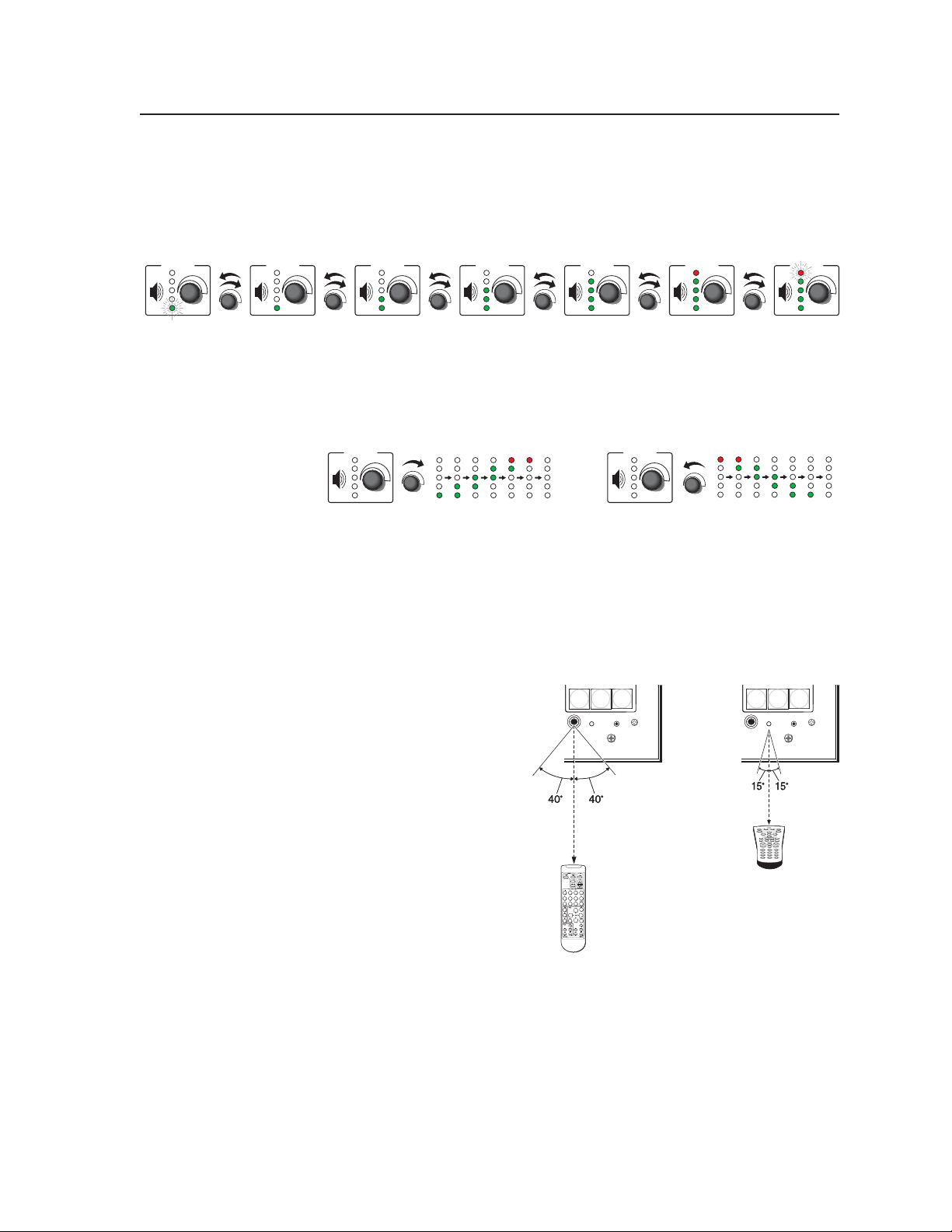
Range-based Volume Adjustment
If the MLC is confi gured for use with a MediaLink Switcher or for some
projectors, the MLC’s LEDs light to indicate volume ranges (with steadily
lit LEDs) and minimum/maximum volume limits (with fl ashing LEDs), as
shown in the following diagram.
VOLUME VOLUM E VOLU ME VO LUMEVOLUM EVOLUM EVOLUM E
Minimum,
0% of Max.
Vol ume
1% to 19%
20% to 39%
of Max.
Vol ume
Vol ume
If the MLC is confi gured for increment/decrement volume
adjustment, the LEDs scroll up/down briefl y. See the example below.
Increment/Decrement-based Volume Adjustment
VOLUM E
IR signal sensors
These sensors allow for IR remote control of the MLC and for IR learning. The
IR remote control must be pointed directly at these devices for best results.
IR control receiver — This larger infrared receiver accepts IR signals from the
e
Extron IR 402 infrared remote control, which mimics the MLC’s front panel
controls.
N
f
If outside interference
(such as fl uorescent
lighting) affects the
MLC’s functioning, you
may need to disable IR
control. Front panel IR
control can be disabled
using the 65# special
function SIS command.
See page 5-40 for details.
IR learning receiver — This
smaller sensor receives and
“learns” commands from
other devices’ infrared
remotes in order to control
the projector or input
devices such as a VCR or
DVD player. IR learning of projector control codes is only necessary if there
are no RS-232 codes available for that projector or if you need to customize
the driver. Refer to the IR Learner help fi le for IR learning procedures. This
receiver accepts infrared signals of from 30 kHz to 62 kHz.
of Max.
40% to 59%
of Max.
Vol ume
60% to 79%
of Max.
Vol ume
5
5
4
4
LAPTOP
LAPTOP
IR
IR
CONFIG
CONFIG
30 feet
30 feet
max.
max.
IR 402
IR 402
6
6
PC
PC
VOLUM E
MLC 226 IP
MLC 226 IP
80% to 99%
of Max.
Vol ume
MLC 226 IP
MLC 226 IP
IR Learning Control
IR Learning Control
LAPTOP
LAPTOP
4
4
5
5
IR
IR
CONFIG
CONFIG
2"–12"
2"–12"
(4–30 cm)
(4–30 cm)
1 2 3
1 2 3
4 5 6
4 5 6
7 8 0 9
7 8 0 9
100% of
Max.
Vol ume
6
6
PC
PC
MLC 226 IP
MLC 226 IP
PRELIMINARY
MLC 226 IP Series • Operation
3-5
Page 36
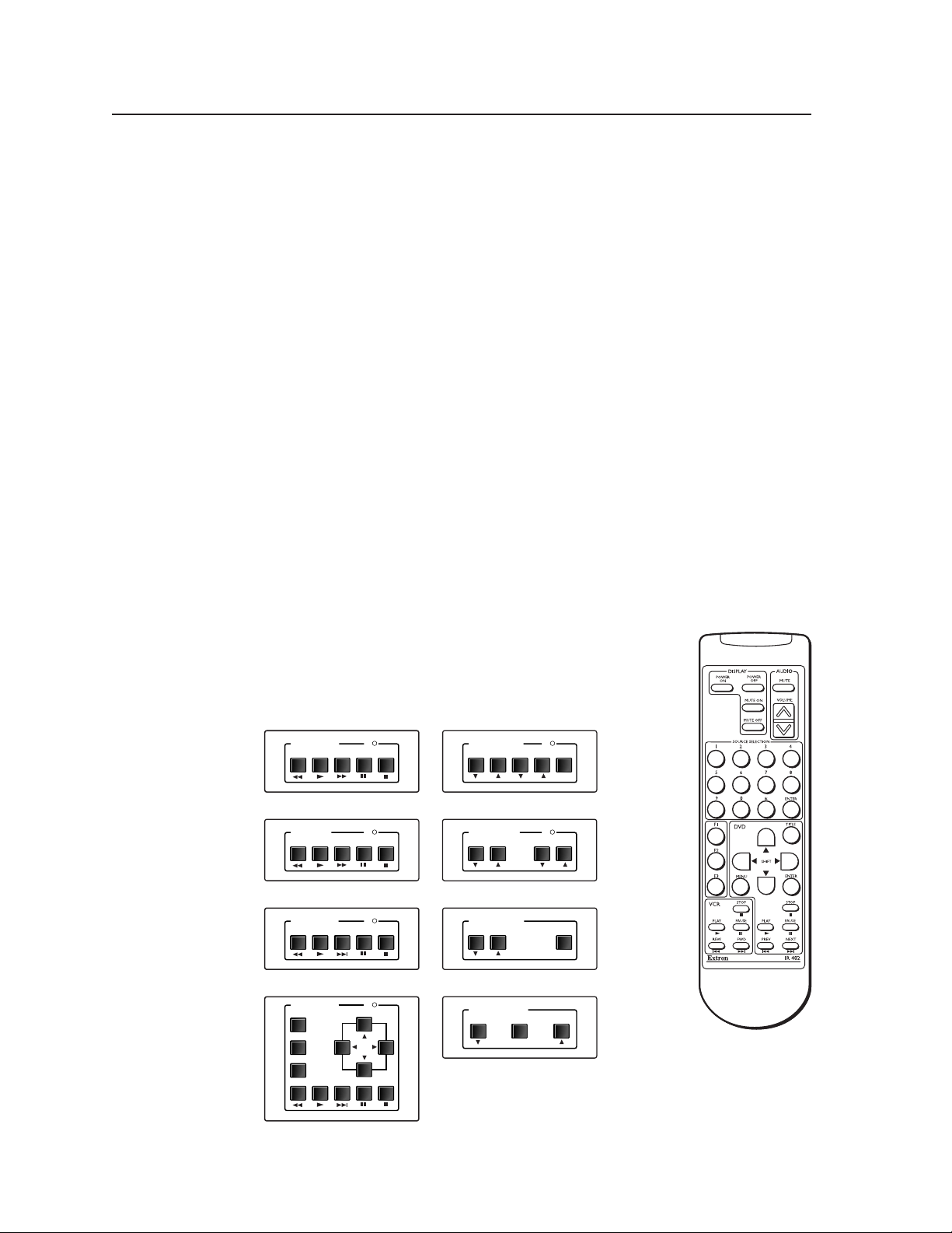
PRELIMINARY
l
l
Operation, cont’d
Confi guration port
Confi g (host control) port — This is a front panel version of the rear panel
g
Host Control port (the 9-pin D connector), and it is independent of that port.
This port makes it possible to upload and confi gure device drivers and also to
initiate IR learning via a front panel connection after the MLC has been installed.
Connect a Windows-based PC or an RS-232 control system to this 2.5 mm
mini stereo-style (tip-ring-sleeve) connector. You can use the Extron 9-pin D
to 2.5 mm stereo mini TRS RS-232 cable (part #70-335-01) or make your own
cable. See page 2-4 for a wiring diagram and port protocol.
N
N
Optional Control Modules and IR 402 Remote Control
The MLC can “learn” IR commands from a VCR’s, DVD’s, tape deck’s or other
device’s remote control, allowing you to create an IR driver fi le that can be
incorporated into the MLC’s event scripts. A command can be associated with
each of the buttons on an optional infrared control module (such as the Extron
IRCM-VCR, IRCM-DVD, IRCM-DVD+, or IRCM-DV+) in order to allow limited
control of source devices. ACM control modules provide limited remote control of
adjustments to a slaved MediaLink Switcher (MLS).
A total of four control modules (a maximum of four control
module addresses) can be installed with this MLC. Refer to the
Control Modules User’s Manual and the IRCM-DV+ Control
Module User’s Manual for installation details. See chapter 4 of
this manual for special instructions for the IRCM-DV+.
VCR CONTROL
REW PLAY FWD PAUSE STOP
This port requires 38400 baud communication, a higher speed than many other
Extron products use. The MLC confi guration software automatically sets
the connection for the appropriate speed. If using HyperTerminal or a similar
application, make sure the PC connected to these ports is set for 38400 baud.
Extron recommends confi guring and controlling the MLC via the LAN
connector. Ethernet connections are faster and more reliable.
Tx
AUDIO CONTROL
INPUT LEVEL MIX LEVEL MUTE
MAX/
MIN
3-6
IRCM-VCR
TAPE DECK
REW PLAY FWD PAUSE STOP
IRCM-Tape
DVD CONTROL
REW PLAY NEXT PAUSE STOP
IRCM-DVD
DVD CONTROL
MENU
TITLE
ENTER
PLAY NEXT PAUSE STOP
REW
IRCM-DVD+
A few optional IRCM, ACM, and RCM control modules
MLC 226 IP Series • Operation
ACM-Level
Tx
Tx
Tx
TONE CONTROL
BASS TREBLE
ROOM CONTROL
SCREEN POSITION LIGHTING
SCREEN POSITION
DOWN UPSTOP
MAX/
MIN
ACM-Tone
ON / OFF
RCM-SCLT
RCM-SC
IR 402
IR 402
IR remote contro
IR remote contro
Page 37

The buttons on the optional IR 402 remote duplicate the MLC’s front panel controls
and also those of a VCR and a DVD player for normal operation. The IR 402 can
also be used to control a MediaLink Switcher. The controller or switcher responds
to commands from the IR 402 remote as if the corresponding button or knob were
pressed or turned on the controller or switcher.
From a distance of no more than 30 feet and within 40° of the axis, the IR 402 sends
infrared (IR) signals to
• a MediaLink Controller via the controller’s front panel IR pickup device or the IR
pickup device of an optional IR signal repeater.
• a MediaLink Switcher via a connected IR signal repeater. The switcher can
receive signals from the IR 402 remote control only via an IR signal repeater.
N
The IR 402 remote’s Display Power buttons, Display Mute buttons, and the VCR
and DVD control buttons will not function until they have been programmed using
GC version 2.2 or higher and uploaded into the MLC.
Setup operations cannot be performed from the remote control.
N
N
IR commands are transmitted from the MLC’s Display RS-232/IR port and IR ports
(via IR Emitters or optional IR Broadcaster) when the corresponding button is
pressed on the remote or on the controller’s, SCP’s, or control module’s front panel.
Refer to the Control Modules User’s Manual.
Pressing the remote’s Display Mute On and Display Mute Off buttons sends the
1M and 0M SIS commands (respectively) to the MLC.
To increase audio volume, press the Volume up (
Volume knob clockwise, or select a larger number in the Control tab of the
MLC’s embedded Web page.
) button, rotate the MLC’s
^
Front Panel Security Lockout ( Executive Mode)
To prevent accidental changes to settings, the MLC features front panel security
lockout (executive) modes for disabling access to controls. When panel lockout
is enabled, no one can make changes using the buttons or volume knobs on the
MLC’s front panel, an IR 402 remote control, SCPs control pad, or control modules.
When the front panel is locked, functions and adjustments can be made only via
RS-232, Telnet, or Web browser control. The Simple Instruction Set (SIS™) command
3X corresponds to this mode (see page 5 -10). For details, see chapters 4 and 5. The
only way to override a front panel lockout via the front panel is to enter a personal
identifi cation number (PIN) to unlock the panel, if conditions allow that.
Enabling and disabling front panel lockout via the embedded Web pages and the front panel
When front panel lockout is enabled, if a button is pressed, the button fl ashes red,
but no change occurs. Nothing—not input switching, projector control, room
control, volume adjustment, or any other knob- or button-executable function—
results from front panel actions when lockout is active. Changes can still be made
via RS-232 or Ethernet (Telnet or Web browser) control.
Front panel lockout can be enabled/disabled using the embedded Web pages
whether or not a PIN has been set. However, a PIN must be set up before you can
enable or disable lockout using the front panel buttons.
PRELIMINARY
MLC 226 IP Series • Operation
3-7
Page 38
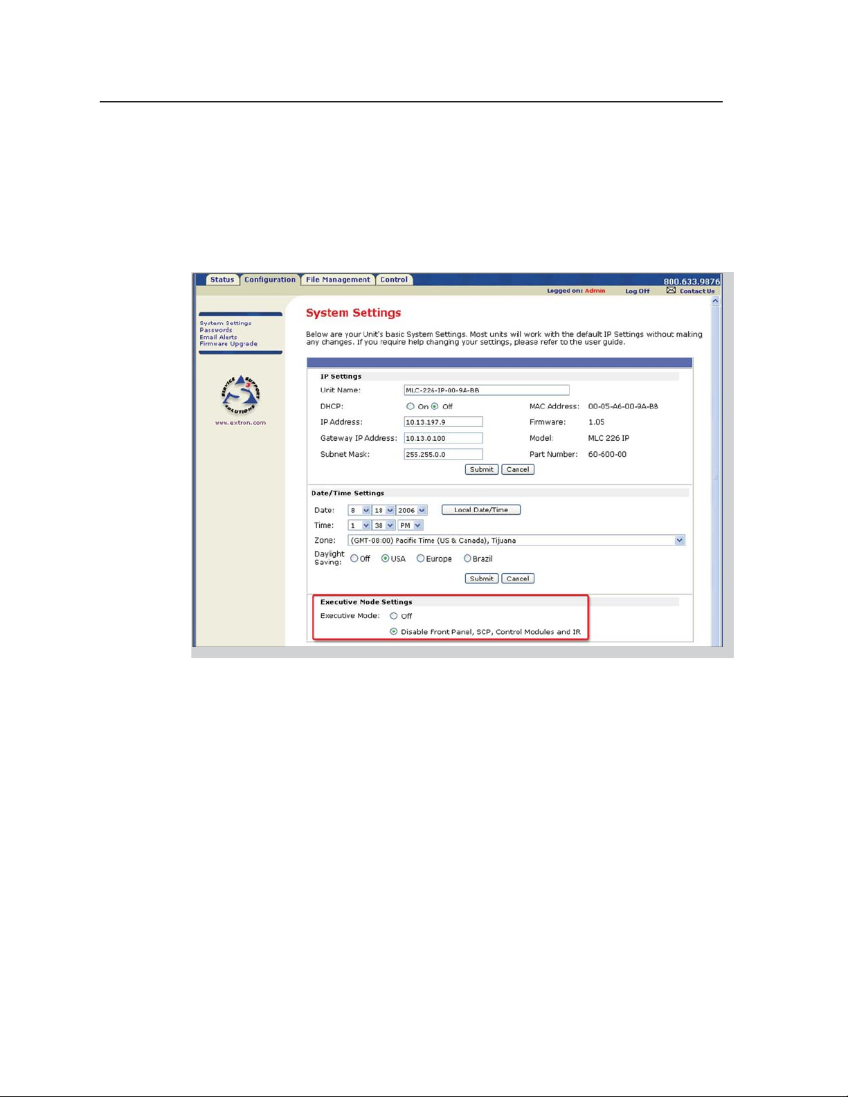
Operation, cont’d
Using the Web pages
1. Using a Web browser, enter the MLC’s IP address and open the MLC’s
embedded Web page. If an administrator password has been set and if you
are prompted to do so, type in the administrator password.
2. Click on the Configuration tab, which opens to the System Settings page.
3. Select either Off or Disable Front Panel, SCP, Control Modules and IR in the
Executive Mode settings area. See the following picture.
PRELIMINARY
N
If Disable Front Panel, SCP, Control Modules and IR is selected via the
System Settings factory default Web page, front panel lockout can’t be enabled/
disabled via the front panel unless PIN Mode is enabled. See pages 5-39 to 5-40
to fi nd the SIS commands for PIN enabling/disabling.
3-8
MLC 226 IP Series • Operation
Page 39

Using the front panel
One or more PINs must be confi gured before this procedure can be used. See
“Preparing the MLC for front panel lockout“ later in this chapter.
N
Locking the Front Panel of an
MLC 226 IP Series Controller
1 2
Press and hold both
Projector On/Off buttons
simultaneously.
The Projector On/Off
buttons light green, the
other buttons dim, and the
bottom Volume LED blinks.
Make sure the projector is off before using a PIN to lock the front panel.
1
DISPLAY
OFF
LIGHT
ON
LIGHT
OFF
AUTO
IMAGE
ON
VOLUME
Unocking the Front Panel of an
MLC 226 IP Series Controller
1 2
Press and hold both
Projector On/Off buttons
simultaneously.
The Projector On/Off
buttons light green, the
other buttons dim, and the
bottom Volume LED blinks.
1
DISPLAY
OFF
LIGHT
ON
LIGHT
OFF
AUTO
IMAGE
ON
VOLUME
While still pressing the
Projector buttons, enter the
PIN. Use the input selection
buttons as a 6-key numeric
keypad; press one button at
a time.
One green Volume LED
lights at a time as the buttons
are pressed.
2a 2b
VCR
1
4
LAPTOP
VIDEO
3
2
5
6
LECTERN
PC
PC
AUX
DVD
2c 2d
This example shows the
default administrator PIN:
1 2a , 3 2b , 4 2c , 6 2d .
Release
all
buttons.
Release
all
buttons.
If the correct PIN is entered, the green Volume LEDs flash and all
buttons flash red 3 times, indicating that front panel is locked, then
return to the way the
ON
If an incorrect PIN is entered, no buttons flash, the green Volume
LEDs turn off, and the red (top) LED blinks. Then the buttons light
as they were lit before front panel lockout was set.
ON
If the correct PIN is entered, the green Volume LEDs flash and all
buttons flash green 3 times, indicating that front panel is locked, then
return to the way they were lit before front panel lockout was set.
ON
If an incorrect PIN is entered, no buttons flash, the green Volume
LEDs turn off, and the red (top) LED blinks. Then the buttons light
as they were lit before front panel lockout was set.
ON
y were lit before front panel lockout was set.
DISPLAY
AUTO
OFF
IMAGE
VOLUME
DISPLAY
VOLUME
DISPLAY
VOLUME
DISPLAY
VOLUME
OFF
OFF
OFF
MUTE
AUTO
IMAGE
MUTE
AUTO
IMAGE
MUTE
AUTO
IMAGE
MUTE
VCR
1
4
LAPTOP
VCR
1
4
LAPTOP
VCR
1
4
LAPTOP
VCR
1
4
LAPTOP
DVD
PC
DVD
PC
DVD
PC
DVD
PC
AUX
VIDEO
3
2
5
6
LECTERN
PC
AUX
VIDEO
3
2
5
6
LECTERN
PC
AUX
VIDEO
3
2
5
6
LECTERN
PC
AUX
VIDEO
3
2
5
6
LECTERN
PC
PRELIMINARY
N
N
The PIN can be entered via either the MLC or the SCP.
Failure to confi gure the On or Off buttons to send display/projector commands
upon button release (instead of button press) may cause problems with the PIN
Mode feature. (If one On/Off button is pressed before the other, and the buttons
are confi gured to send commands at the button press, the fi rst button’s actions
can be executed, preventing you from locking the front panel until the display’s
warmup or cooldown period fi nishes.)
MLC 226 IP Series • Operation
3-9
Page 40
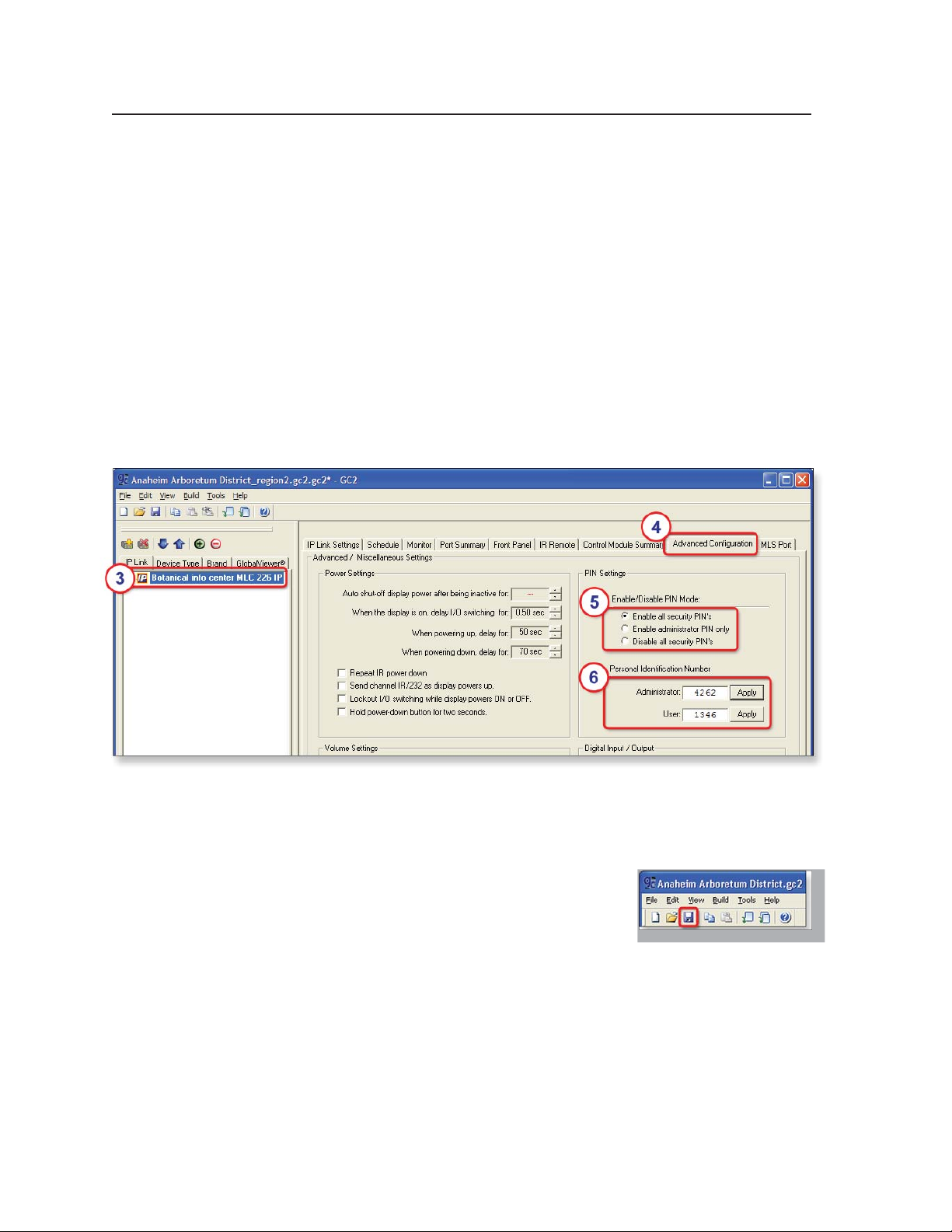
Operation, cont’d
Preparing the MLC for front panel lockout
To allow access to front panel changes to specifi c personnel while the front panel is
locked, you can set a user and/or administrator PIN and set which type of PIN, if
any, is allowed to unlock the panel.
Setting up and enabling or disabling PINs
1. Install and start the Extron Global Confi gurator (GC) software. See chapter 4.
2. Open an existing GC project or start a new project. Refer to the GC help fi le or
the MLC 226 IP Series Setup Guide for instructions.
3. In the IP Link tab area on the left side of the screen, click on the name of the
MLC you want to set up.
4. Click on the Advanced Configuration tab.
5. Select which PIN to enable (which PIN will be allowed to unlock the front
panel), or disable both PINs so that no one can access the front panel during
front panel lockout.
PRELIMINARY
6. Type in the four-digit PINs for the administrator and for users. Each digit of
the PIN must be a number from 1 to 6 because they represent the MLC’s six
input buttons, which will be used as a numeric keypad. By default, both PINs
are set to 1346.
7. Complete the rest of the confi guration, then save
the project: click File and then Save or click the
Save icon, shown at right.
8. Upload (build) the confi guration to the MLC.
3-10
MLC 226 IP Series • Operation
Page 41

Scheduling front panel lockouts
You can set the MLC’s front panel to be automatically locked at certain times and
days by setting up a schedule and uploading it to the MLC.
1. Start the Extron Global Confi gurator (GC) software. See chapter 4.
2. Open an existing GC project or start a new project. Refer to the GC help fi le or
the MLC 226 IP Series Setup Guide for instructions.
3. In the IP Link tab area on the left side of the screen, click on the name of the
MLC you want to set up.
4. Click on the Schedule tab in the right side of the screen, as shown below.
5. Click Add Schedule. The Scheduled Actions Wizard window appears.
PRELIMINARY
MLC 226 IP Series • Operation
3-11
Page 42

Operation, cont’d
6. Type in a name for the schedule that will automatically lock the MLC’s panel.
7. In the Schedule Times area, select the days and hours when front panel
lockout should start.
PRELIMINARY
8. Click Next.
9. Set up the front panel lockout action for the MLC. See the illustration on the
following page.
a. Check the Action check box.
b. Select the MLC, itself, from the Subject Ports list.
c. Click on Lockout Front Panel in the Available Options list. A default
description appears in the Action Name area. If desired, you can change
the name assigned to this action.
d. Click Apply Action.
e. Click Done. The Scheduled Actions Wizard window closes.
3-12
MLC 226 IP Series • Operation
Page 43

10. Click Add Schedule. The Scheduled Actions Wizard window reappears.
11. Type in a name for the schedule that will automatically unlock the MLC’s
panel.
12. In the Schedule Times area, select the days and hours when the front panel
should be unlocked.
13. Click Next.
14. Set up the front panel unlock action for the MLC.
a. Check the Action check box.
b. Select the MLC, itself, from the Subject Ports list.
c. Click on Unlock Front Panel in the Available Options list. If desired, you
can change the name assigned to this action in the Action Name area.
d. Click Apply Action.
e. Click Done. The Scheduled Actions Wizard window closes.
15. Save the project: click File and then Save or click the Save icon.
16. Upload the project to the MLC.
a. Click the Build menu and select one of the options (Build Changed
Configurations or Build All Configurations).
b. Click the Begin button.
c. When the uploading is fi nished, click Close.
PRELIMINARY
MLC 226 IP Series • Operation
3-13
Page 44

Operation, cont’d
PRELIMINARY
3-14
MLC 226 IP Series • Operation
Page 45

MLC 226 IP Series
Chapter Four
4
Software-based Confi guration
and Control
Confi guration and Control: an Overview
The Basic Steps: A Guide to this Chapter and Other Resources
Confi guring the MLC for Network Communication
Global Confi gurator Software for Windows
®
PRELIMINARY
Advanced Confi guration
Controlling the MLC
Customizing the MLC’s Control Web Pages
Page 46

Software-based Confi guration and Control
Confi guration and Control: an Overview
An MLC 226 IP Series controller must be confi gured before use or it will not be
able to control other devices. The MLC 226 IP can be confi gured and controlled via
a host computer attached to the rear panel Host Control port or LAN port, or the
front panel Confi g port. See chapter 2 for pin assignments and other details on the
confi guration and control ports.
PRELIMINARY
N
• The primary means for confi guring the controller is by using the Extron Global
N
• Alternatively, the default Web pages embedded within the MLC 226 IP provide
N
• The third way to control and confi gure the controller is by using Simple
Extron recommends confi guring and controlling the MLC via the LAN
connector. Ethernet connections are faster and more reliable.
Confi gurator (GC) software. This method requires a properly confi gured PC
with Windows
Global Confi gurator generates GlobalViewer™ Web pages that are uploaded
to the MLC and can be used to control the MLC and make adjustments to its
settings.
Microsoft Internet Explorer is currently the only Web browser that supports
a means to perform some setup, adjustment, and control via a Web browser
(Netscape Navigator version 6.0+, Internet Explorer version 5.5+, or Mozilla
Firefox version 1.0+) from any type of network-enabled computer.
Netscape and Firefox cannot be used for viewing the Serial Control pages of the
Instruction Set (SIS) commands via Telnet, a Web browser, or RS-232. SIS
commands are discussed in detail in chapter 5.
©
2000, Windows XP, or a higher version of Windows installed.
GlobalViewer pages.
factory-embedded Web page. Run Internet Explorer to use those pages.
The Basic Steps: a Guide to this Chapter and Other Resources
1
Confi gure the MLC for network communication. See “Confi guring the MLC
for Network Communication“ in this chapter.
2
Download or install Global Confi gurator and other Extron software (IR
Learner) and device drivers. See chapter 1 of the MLC 226 IP Series Setup
Guide, the software disk(s) that were shipped with the unit, and the Extron
Web site (www.extron.com) for instructions.
N
The printed MLC 226 IP Series Setup Guide is shipped with the MLC. It
is also available as a PDF fi le on the Extron Web site (www.extron.com). The
CD included with the unit contains software, device drivers, a PDF fi le of the
full user’s manual, and additional documentation available when the unit was
shipped. The setup guide outlines most of the common tasks required to set up
an MLC.
4-2
3
Create a Global Confi gurator project and confi gure basic settings and
functions. See the MLC 226 IP Series Setup Guide, chapter 3, for step-by-step
procedures.
4
Confi gure additional or advanced functions, if desired. See “Advanced
Confi guration,” later in this chapter, for information on IR learning and on
advanced confi guration options in Global Confi gurator.
5
Save and upload the confi guration to the MLC. See the MLC 226 IP Series
Setup Guide, chapter 3.
MLC 226 IP Series • Software-based Confi guration and Control
Page 47

6
Control the MLC and devices connected to it by using the MLC’s embedded
Web pages or its GlobalViewer (GV) Web pages. See “Controlling the MLC,”
later in this chapter.
Confi guring the MLC for Network Communication
To function together, both the PC and the MLC 226 IP must be confi gured correctly.
Unless you use an RS-232 connection for all setup and communication with the
controller, the PC must be network-capable with the proper protocols, and the
MLC 226 IP must be set up so it can be connected to a LAN (local area network).
When you power on the MLC 226 IP for the fi rst time, you have a choice of several
ways to set up the controller’s IP address:
• Use the Global Confi gurator software via an Ethernet connection.
• Use the ARP command with an Ethernet connection.
• Use a Web browser with an Ethernet connection.
• Use SIS commands via an RS-232 connection, or Telnet with an Ethernet
connection.
If you use a Web browser or Telnet the fi rst time you connect a PC to the controller
via IP, you must temporarily confi gure the PC to communicate with the controller.
See “Setting up the PC for IP communication with an MLC” later in this chapter.
Then you must change the controller’s default settings (IP address, subnet mask,
and [optional] administrator name and password) in order to use the unit on an
intranet (LAN) or on the Internet (WAN). After you have set up the MLC 226 IP for
network communication, you can reset the PC to its original network confi guration.
MLC 226 IP’s RS-232 protocol:
• 38400 baud
• 8 data bits
• 1 stop bit
• No parity
• No fl ow control
PRELIMINARY
N
MLC 226’s LAN port defaults:
• MLC’s IP address: 192.168.254.254
• Gateway’s IP address: 0.0.0.0
• Subnet mask: 255.255.0.0
• DHCP: off
• Link speed and duplex level: autodetected
Once the controller has been confi gured, an Ethernet (intranet or Internet)
connection can subsequently be used to contact, confi gure, or control it.
N
The following instructions assume that you have already connected the Windowsbased PC to the MLC 226 IP’s LAN port or to the Host Control port or Confi g port,
and powered on the controller and the PC.
Both confi guration ports require 38400 baud communication. This is a
higher speed than many other Extron products use. The Global Confi gurator
program automatically sets the connection for the appropriate speed. If using
HyperTerminal or a similar application, make sure the PC or control system
connected to these ports is set for 38400 baud.
Both your computer and the MLC must be connected to the same LAN.
Alternatively, you can use a crossover Ethernet cable to connect the controller
directly to your computer’s Ethernet card.
MLC 226 IP Series • Software-based Confi guration and Control
4-3
Page 48

PRELIMINARY
Software-based Confi guration and Control, cont’d
Confi guring the MLC for network communication via Global
Confi gurator software
You can confi gure the controller’s IP address via an IP/Ethernet connection using
the Extron Global Confi gurator (GC) Windows-based software.
Read the Global Confi gurator help fi le for basic information on using
Global Confi gurator software and setting up a project. Also read the MLC 226 IP
Series Setup Guide, revision B or higher, included with the controller, for step-by-step
instructions of how to use GC to set up the MLC 226 IP’s IP address.
Confi guring the MLC for network communication using the
ARP command
You can use the ARP (address resolution protocol) command to set up an IP
address for the controller. The ARP command tells your computer to associate the
controller’s MAC (media access control) address with the assigned IP address. You
must then use the ping utility to access the controller, at which point the controller’s
IP address is reconfi gured.
Use ARP to confi gure the MLC 226 IP’s IP address as follows:
1. Obtain a valid IP address for the controller from your network administrator.
2. Obtain the controller’s MAC address (UID #) from the label on its rear, top, or
side panel. The MAC address should have this format: 00-05-A6-xx-xx-xx.
3. If the MLC has never been confi gured and is still set for factory defaults, go
to step 4. If not, perform a Mode 4 system reset. For detailed information on
reset modes, see “Resetting the Unit” in chapter 2, “Installation.”
C
4. At the PC, access the MS-DOS command prompt, then enter the arp –s
arp –s 10.13.197.9 00-05-A6-00-9A-BB
The MLC 226 IP must be confi gured with the factory default IP address
(192.168.254.254) before the ARP command is executed, as described below.
command. Enter the desired new IP address for the MLC and the
MLC 226 IP’s MAC address. For example:
4-4
N
After the arp -s command is issued, the controller changes to the new address
5. Execute a ping command by entering “ping” followed by a space and the new
ping 10.13.197.9
You must ping the MLC in order for the IP address change to take place.
MLC 226 IP Series • Software-based Confi guration and Control
The MAC address is listed on the controller’s rear or bottom panel.
and starts responding to the ping requests, as described in the next step.
IP address at the command prompt. For example:
The response should show the controller’s new IP address, as shown in the
following picture.
Page 49

You can reconnect using either Telnet or a Web browser to verify that the
update was successful.
6. After verifying that the IP address change was successful, enter and issue the
arp –d command at the DOS prompt. For example:
arp –d 10.13.197.9 removes 10.13.197.9 from the ARP table
or
arp –d* removes all static IP addresses from the ARP table.
Confi guring the MLC for network communication via a Web
browser
The default Web pages that are preloaded on the MLC 226 IP are compatible
with popular Web browsers such as Netscape Navigator (version 6.0 or higher),
Internet Explorer (version 5.5 or higher), or Mozilla Firefox (version 1.0 or higher).
However, the MLC and the PC must both be part of the same subnet before they
can communicate via the LAN port. You must change the PC’s IP address to one
that is on the same subnet as the default IP address of the MLC (192.168.254.254).
PRELIMINARY
N
1. Temporarily change the host PC’s IP address. See “Setting up the PC for
2. Obtain a valid IP address for the controller from your network administrator.
3. Launch the Web browser on the connected PC (for which you set up the
4. Select the Configuration tab, then select System Settings from the menu on
This method requires a crossover cable. See page 2-14 for cabling details.
IP communication with the MLC” later in this chapter for step-by-step
instructions.
network confi guration earlier), and enter “http://192.168.254.254/” in the
address box. The MLC 226 IP’s default Web page is displayed.
the left of the screen. A Web page appears. The top half of a typical screen is
shown in the following picture.
MLC 226 IP Series • Software-based Confi guration and Control
4-5
Page 50

PRELIMINARY
Software-based Confi guration and Control, cont’d
5. Set the MLC for the new IP address using either step 5a or step 5b.
a. Enter the new IP address for the MLC, the corresponding subnet mask,
and the gateway address, then click on the Submit button. IP addresses,
subnet mask, and e-mail addresses follow standard naming and
numbering conventions/protocol. The IP network administrator should
provide the IP addresses and subnet mask to be used with this controller.
It takes a minute or so for the controller to store the new settings. Once
the controller’s IP address is changed, you lose communication with the
controller.
b. Select DHCP On, then click Submit. It takes a minute or so for the
controller to store the new settings. Once the controller’s IP address is
changed, you lose communication with the controller.
6. Close the browser.
7. After changing the controller’s IP settings, change your PC’s TCP/IP settings
back to their original confi guration.
4-6
Confi guring the MLC for network communication using SIS
commands
RS-232
The MLC can also be confi gured using serial (RS-232) communication and a
terminal emulation program such as HyperTerminal, which is installed with
Windows. For information on RS-232 port requirements (including 38400 baud)
and on Simple Instruction Set (SIS) commands, variables, and syntax, see chapter 5.
Telnet
The MLC and the PC must both be part of the same subnet before they can
communicate via the LAN port. You must change the PC’s IP address to one that is
on the same subnet as the default IP address of the MLC (192.168.254.254).
N
1. Temporarily change the host PC’s IP address. See “Setting up the PC for
MLC 226 IP Series • Software-based Confi guration and Control
This method requires connecting the MLC to the PC’s LAN port using a
crossover network cable. See pages 2-13 and 2-14 for cabling details.
IP communication with an MLC” later in this chapter for step-by-step
instructions.
Page 51
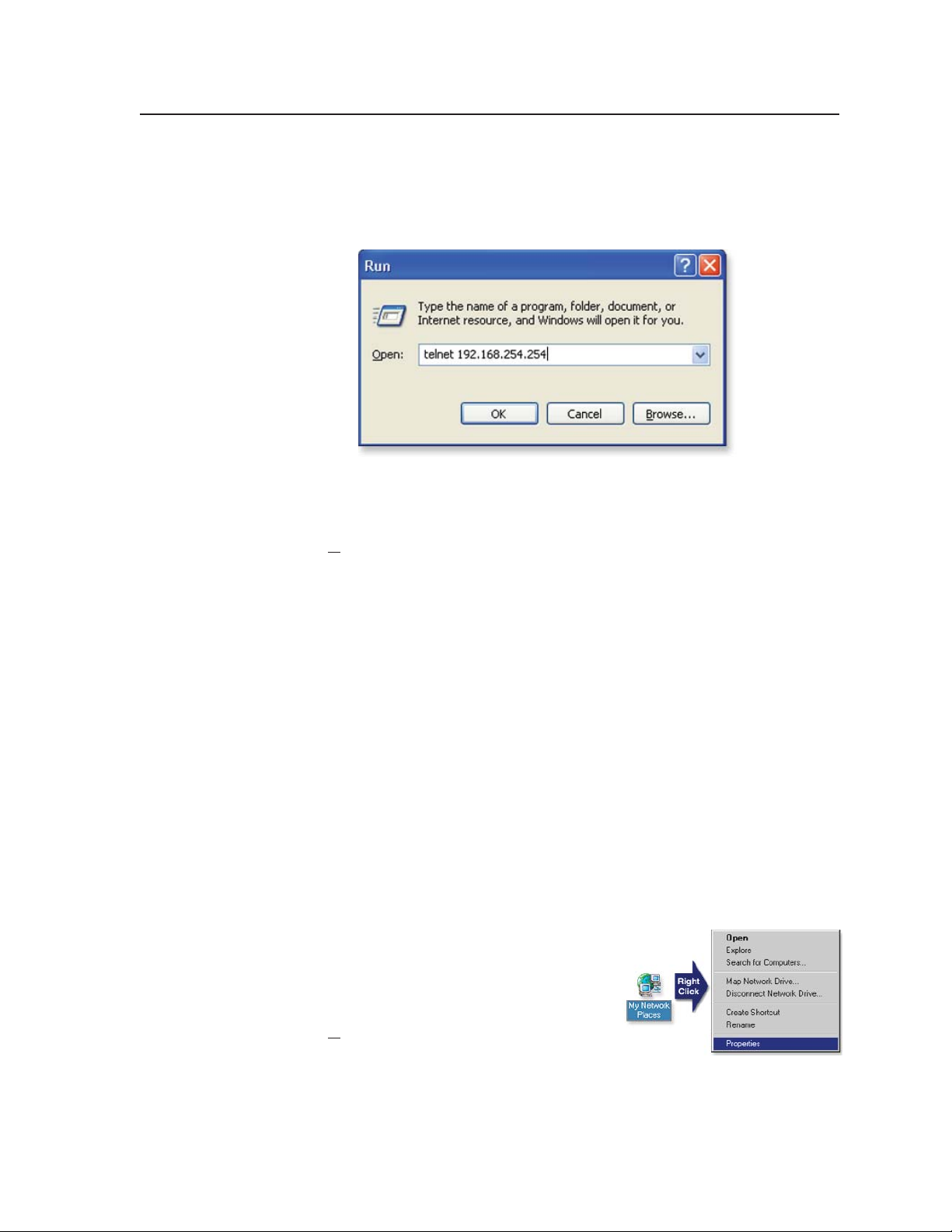
2. Start Telnet on the PC
a. Click the Start menu and select Run. The Run dialog box appears.
b. Ty pe telnet, a space, and the default IP address (192.168.254.254) into the
Open area, and click OK.
3. Set the MLC for the new IP address by doing one of the following:
• Enter SIS command
chapter 5, “SIS™ Programming and Control”) to set the IP address.
or
• Enter SIS command 1DH
4. After changing the controller’s IP address, change your PC’s TCP/IP settings
back to their original confi guration.
E X1$
}
CI
, where
}
to enable DHCP.
X1$
is the new IP address (see
Setting up the PC for IP communication with an MLC
You need a Windows-based (Windows 2000, XP, or higher) PC equipped with an
operating network adapter. To allow your PC to work with Extron’s Ethernetcontrolled products, the TCP/IP protocol must be installed and properly
confi gured.
When setting up the MLC for network communication via a Web browser or Telnet
connection, you must change the IP address of the PC to one that is on the same
subnet as the MLC. This is not required if you are setting up the MLC for network
communication via Global Confi gurator, the ARP command, or SIS commands via
an RS-232 connection.
If you use an existing Ethernet LAN intranet, your network administrator can
provide you with a unique IP address for the controller or confi rm whether you
need to set up the MLC 226 IP for DHCP (Dynamic Host Confi guration Protocol) to
have an address assigned automatically when you sign on.
1. Open the Network Connections page as follows:
• Locate and right-click on My Network
Places on the Windows (2000, XP,
or higher) desktop, then click on
Properties.
or
• Click on the Start menu, click on
Settings (if needed), click on Control Panel, then double-click on
Network and Dial-up Connections (Windows 2000) or Network
Connections (Windows XP).
PRELIMINARY
MLC 226 IP Series • Software-based Confi guration and Control
4-7
Page 52

PRELIMINARY
Software-based Confi guration and Control, cont’d
2. Right-click on Local Area Connection, then select Properties.
3. Select Internet Protocol (TCP/IP)
and click on the Properties button.
If Internet Protocol (TCP/IP) is not
on the list, it must be added
(installed). Refer to the Windows
user’s manual or the Windows
online help system for information
on how to install the TCP/IP
protocol.
4. Write down the PC’s current IP
address and subnet mask below.
If your PC is set to “Obtain an IP
address automatically,” make a note
of that, instead. You will need to
restore these settings to the PC later.
IP address:
. . . .
Subnet mask:
. . . .
5. Change the PC’s IP address so it can communicate with the MLC 226 IP and
change the controller’s IP settings.
a. Select the “Use the following IP address:” radio button.
b. Enter the following values, as shown in the following picture:
IP address: 192.168.254.253
Subnet mask: 255.255.0.0
Default gateway: blank or 0.0.0.0
4-8
MLC 226 IP Series • Software-based Confi guration and Control
Page 53

c. Click the OK button to save the changes and exit the network setup.
Reboot the PC, if required, for the changes to become effective.
6. Plug one end of a Category 5 network/Ethernet crossover cable into the
MLC’s Ethernet (LAN) connector. Refer to chapter 2 for RJ-45 LAN connector
wiring. Plug the other end of the Ethernet cable into the Ethernet port on the
PC.
N
7. Set up the MLC’s IP address using a Web browser or SIS commands as
8. Restore the PC’s previous IP confi guration by following steps 1, 2, 3, and 5 but
If a network hub or switch is used between the PC and the MLC 226 IP, use a
straight-through Category 5 cable instead of a crossover cable.
described earlier in this chapter.
using the PC’s original IP address settings you wrote down in step 4.
Global Confi gurator Software for Windows®
The included Extron Global Confi gurator (GC) program for Windows offers the
most complete way to confi gure and customize the controller via either RS-232
or IP connection. GC provides the ability to generate a Web browser-based
GlobalViewer™ (GV) application and Web pages for each IP Link-based device (IP
Link interface, System 5 IP, MLC 226 IP, MLC 104 IP, or other Extron device) on a
network. Once an MLC 226 IP is confi gured, its GlobalViewer Web pages allow the
user to manage, monitor, and control the MLC and the devices connected to it.
Global Confi gurator offers the best and easiest way to confi gure the controller.
Other setup options include using Simple Instruction Set (SIS
MLC’s factory-embedded Web pages, but many setup features are available only
via Global Confi gurator. GC includes some functions found on the controller’s
front panel and many additional features that are available only through the software.
™
) commands and the
PRELIMINARY
Downloading the software and getting started
Global Confi gurator software is included with the controller. Global Confi gurator
software updates and a large variety of device drivers can be downloaded at no
charge from the Extron Web site (http://www.extron.com).
N
Device drivers (for controlling projectors, VCRs, DVD players, etc.) can be used
by other Extron IP Link
site as an IP Link driver package. You may also want to download the optional
™
products, so they may be listed on the Extron Web
MLC 226 IP Series • Software-based Confi guration and Control
4-9
Page 54

PRELIMINARY
Software-based Confi guration and Control, cont’d
IR Learner™, a free software utility for capturing infrared codes from a handheld
IR remote control to create custom drivers for operating IR-controlled devices
like the MLC that use IP Link® and GlobalViewer.
N
Refer to the MLC 226 IP Series Setup Guide for specifi c information on how to
download the software. Refer to that guide and to the Global Confi gurator help
fi le for details and step-by-step procedures on how to start a GC project and
perform basic setup tasks for an MLC 226 IP. Both the setup guide and the help
fi le contain instructions on how to set the MLC’s IP address, gateway IP address,
subnet mask, mail server IP address, domain name, Telnet port, Web port, SMTP
username, and SMTP password so that the MLC is able to communicate with
the network. Obtain these parameters from your network administrator before
continuing.
PC system requirements
The MLC 226 IP and Global Confi gurator have the following hardware and
software requirements:
• Intel
• Microsoft
• Microsoft Internet Explorer
• Microsoft Windows Script 5.6
• 512 MB of RAM
• 50 MB of available hard disk space
• A network connection with a minimum data transfer rate of 10 Mbps (100 Mbps
C
Do not change the directory or the name of the directory where the software fi les
are installed by default.
®
Pentium® III 1 GHz processor
®
Windows® operating system
• Windows NT service pack 4, or
• Windows 2000 service pack 2, or
• Windows XP service pack 2
®
6.0 with ActiveX® enabled
is recommended)
Do not run this software on a PC that uses an earlier version of Windows.
4-10
Using Global Confi gurator: helpful tips
Resources and notes
• Some items in Global Confi gurator correspond directly to the front panel
controls. See chapter 3, “Operations,” for features and settings.
• The Global Confi gurator help fi le provides information on settings and on how
to use the Global Confi gurator program, itself.
• Basic setup steps are covered in the MLC 226 IP Series Setup Guide, which is
shipped with the MLC. It includes instructions and examples on how to use the
basic tabs in GC.
• If you will confi gure the MLC at the installation site, Extron recommends using
the driver subscription function to download drivers for all manufacturer and
device types before you go out into the fi eld.
• The Global Confi gurator project fi le contains confi guration settings, and it can be
saved to a directory or folder for backup or for installation on another MLC 226
Series controller. Saving a confi guration is recommended before you perform a
fi rmware upgrade.
MLC 226 IP Series • Software-based Confi guration and Control
Page 55
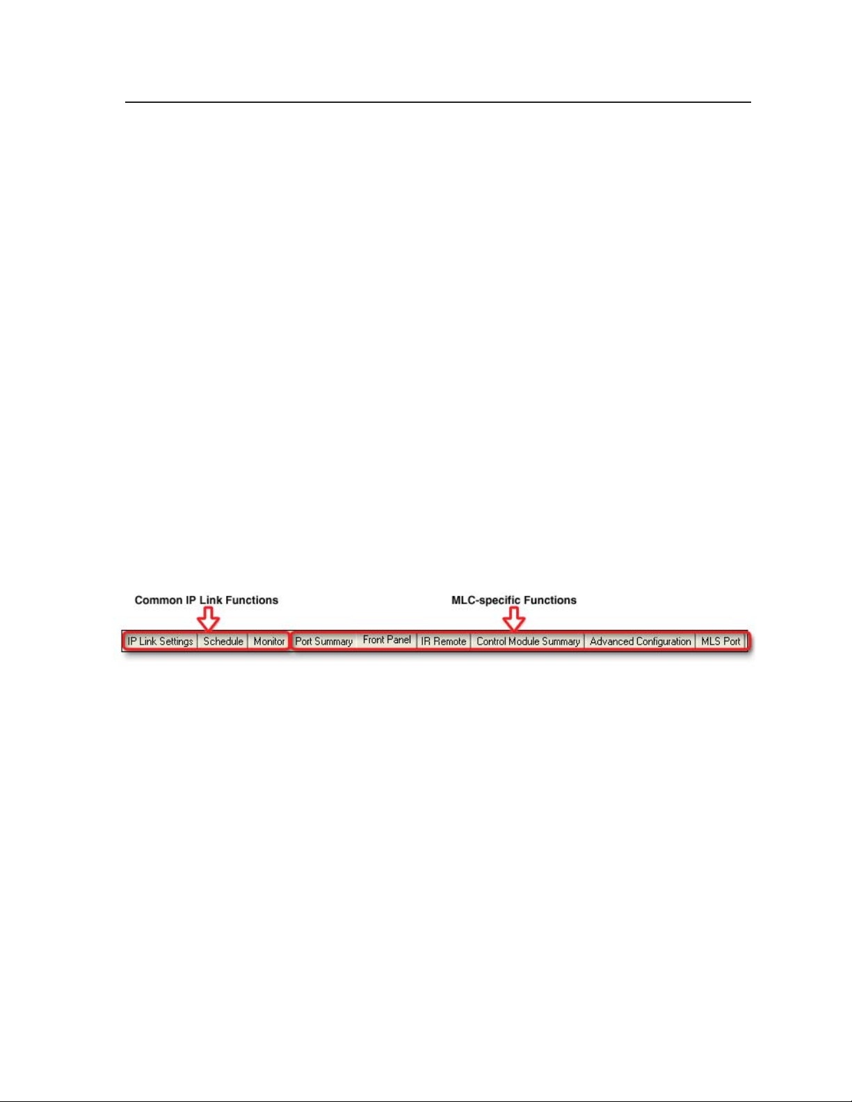
• The MLC can be set up to allow confi guration access to administrators only,
and to prevent other users from making changes to the controller’s settings,
events, and drivers. If an administrator password is set for the controller, nonadministrator end users can select inputs and adjust output volume but are
prevented from making any other changes using GlobalViewer Web pages.
• IP addresses, subnet mask, and e-mail addresses follow standard naming and
numbering protocol. The network administrator provides the IP addresses and
subnet mask to be used with this controller.
• The unit name is any name (e.g., Room107MLC226IP, Lab1234mlc226IP,
ConfRoomSystem, LectureHall8-cntrlr, etc.) that you want to use to label a
specifi c MLC controller unit. The default is a combination of the product
name and part of the hardware address. This can be changed to your choice of
alphanumeric characters and hyphens (-).
• Spaces are not permitted within a unit’s name.
• Underscores (_) are not permitted.
• Valid characters are A-Z, a-z, 0-9, and - (hyphen).
• The name cannot start with a number or a hyphen, and it cannot end with a
hyphen.
• Maximum name length is 24 characters.
A brief guide to Global Confi gurator’s tabs
In the upper right side of the GC software window are several tabs that divide
the program into groups of functions you can view and confi gure. The left three,
IP Link Settings, Schedule, and Monitor, are displayed for all IP Link-enabled
products. Any tabs to the right of those three vary in quantity, type, and layout,
depending on the product being confi gured. See the illustration below for an
example of the tabs that may be available when you confi gure an MLC.
IP Link Settings shows all the IP-related settings, as well as the unit part number,
MAC address and fi rmware version. You can view the IP address of the
controller and the unit administrator and user passwords here. However, the
IP address, passwords, and other items (gateway address, domain name, mail
server; unit name; system time, and the like) must be set by selecting Change
Device Settings from GC’s Tools drop-down menu.
Schedule is the tab where you select the days of the week and times for the MLC
to automatically turn the projector or other devices on and off, send e-mails, and
lock/unlock the front panel.
Monitor is the tab where you set up conditions/ports for the MLC to monitor. You
also use this part of the software to set up actions and confi gure appropriate
e-mails to send out in response to various conditions like projector disconnection
or excessive projector lamp hours.
Port Summary is an information-only tab. Click on it to display the following
items:
• names of the MLC’s ports (Display; IR/RS-232 output ports A, B, and C; and
MLS) or the devices connected to them
• port signal type (IR or serial)
• serial communication mode (RS-232 or RS-422)
• any device driver associated with that port
PRELIMINARY
MLC 226 IP Series • Software-based Confi guration and Control
4-11
Page 56

Software-based Confi guration and Control, cont’d
Front Panel allows you to confi gure and label each front panel button and to
associate actions, commands, drivers, and relay functions with the MLC’s front
panel buttons.
N
System Remote is the tab where you can confi gure and label each button on the
Control Module Summary displays a summary of which, if any, control modules
Advanced Configuration provides a way to confi gure power-up/power-down
Auxiliary Port allows you to select and confi gure a model of MediaLink Switcher
Failure to confi gure the On or Off buttons to send their commands upon button
release (instead of at the button press) may cause problems with the PIN Mode
feature.
IR 402 remote control and associate commands, drivers, and assorted functions
with the remote’s buttons.
(IRCMs, CMs, ACMs, RCMs) are to be used with the selected MLC, what
their DIP switch addresses are, and how many (if any) commands have been
associated with each module so far. This tab also lets you remove or add control
modules to the system, as long as you don’t exceed the four allowed addresses
(up to four modules). A visual example of each control module appears when
you click on the name of the module in the Available Control Modules area.
cycle settings, personal identifi cation numbers (PINs) and PIN enabling, volume
adjustment parameters, digital ports, and miscellaneous settings. See “Advanced
confi guration options in Global Confi gurator,“ later in this chapter.
(MLS) or PoleVault
MLS RS-232 port). See “Confi guring an auxiliary switcher,” later in this chapter.
™
Switcher (PVS) to control using the MLC (via the MLC’s
PRELIMINARY
Advanced Confi guration
IR learning to create customized IR driver fi les
If you do not fi nd a driver on the Extron Web site for the device you plan to
use, you can create your own IR driver fi le. Extron IR Learner™ software lets
you create a customized driver fi le of IR commands that can be used with the
Global Confi gurator software for port setup and button confi guration. Visit
http://www.extron.com to download IR Learner and install it on your PC.
Once IR Learner is installed on the PC, you can start the program directly
by double-clicking the IR Learner icon, shown at right.
Or, you can select Run IR Learner from Global Confi gurator’s Tools
menu, as shown at right. The IR Learner utility opens in a new window. With this
tool you can create a driver fi le of IR
commands that can then be loaded into
the driver list and used for port setup
and button confi guration in the MLC.
Additional information on how to
use the software is available in the IR
Learner help fi le.
Advanced confi guration options in Global Confi gurator
In Global Confi gurator in the Advanced Configuration tab you can set
• what happens during power-up and power-down cycles and for how long
• personal identifi cation numbers (PINs) and whether or not each PIN is enabled
during front panel lockout (executive mode) (see page 3-9 for details)
• volume adjustment parameters
• confi guration for each digital port
4-12
MLC 226 IP Series • Software-based Confi guration and Control
Page 57
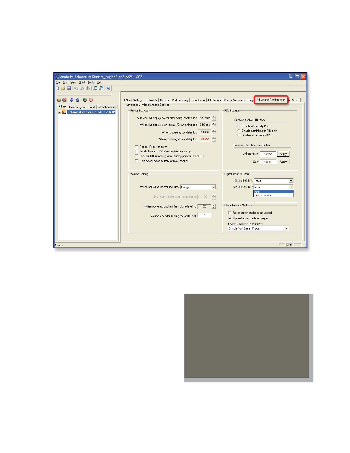
• miscellaneous settings, including whether to reset button statistics or upload the
enhanced Web pages when the confi guration is uploaded to the MLC
Display power up/power down settings (Power Settings)
All the settings in this section affect what happens during display power on/up
and power off/down cycles.
Auto shut-off period — This feature at the top of the Power Settings area lets you
set the length of time that
the display or projector can
be inactive before the MLC
automatically turns it off.
Settings can be 30 to 720
minutes or -- (0).
I/O switching delay
periods — The second
item in this area controls
whether and how long to
prevent (lock out) input
switching after an input
has been switched. This
delay can be set to 0 to 5
seconds in half-second intervals, and it is similar to special SIS command 54# on
page 5-40.
PRELIMINARY
MLC 226 IP Series • Software-based Confi guration and Control
4-13
Page 58

Software-based Confi guration and Control, cont’d
Most projectors do not accept commands during warm up and cool down
periods. The next two settings in this area specify the amount of time (0 to 300
seconds in 2-second intervals) for the MLC to wait between issuing a projector
power-on or power-off command and when the next input button press can
occur. These delays can also be set using special SIS commands (see pages 5-34,
and 5-39 through 5-40).
Repeat IR power down — Select this setting to have the MLC send out infrared
power-off commands to the display or projector twice in a row instead of once.
The MLC must be confi gured to send the IR power off command upon display
power off button release (not at the button press).
Send channel IR/232 as display powers up — Select this setting to make the
MLC send out commands associated with the currently selected input button
while the projector or display is powering on. Using this setting ensures that the
MLC’s and the display device’s inputs are coordinated.
Lockout I/O switching while display powers On or Off — To prevent users from
changing inputs during the entire power-on or power-off period, select this
setting.
Hold power-down button
for two seconds — Select
this setting to require
users to press and hold the
Display Off button for two
seconds to start the display
power-down process.
This prevents users from
shutting down the display
or projector by accidentally
pressing the button.
PRELIMINARY
Volume settings
When adjusting the volume, use — Volume control for a projector, display, or
audio output device involves one of two methods: selecting a setting within a
specifi c range of values, or sending a simple command to increase or decrease the
volume by a fi xed increment. Select the appropriate method for the equipment
you are using. Refer to the user’s manual for the display or audio device.
If you choose Range, you can set the maximum quantity of volume change
steps. You can also set the specifi c level the audio output should not exceed
when the projector/display is powered on.
N
Volume encoder scaling factor (0-255) — This feature allows you to slow down
The power-up volume limit is limited by the maximum volume setting (SIS
special command 47#). If the maximum volume (47# command) is set, the
limit audio level feature (SIS special command 11#) is automatically set to 25%
of the maximum volume (47#). See pages 5-34 and 5-39.
the volume knob (the encoder) on the MLC’s front panel. The value entered in
the encoder scale area is the encoder speed scaling factor. A value of 1 scales the
speed down by a factor of 2 (the MLC issues commands at 1/2 speed), a value of
2 scales by a factor of 3 (the MLC issues volume commands 1/3 speed), and so
forth. A factor of zero sets the MLC for no scaling: the volume encoder works at
full speed.
4-14
MLC 226 IP Series • Software-based Confi guration and Control
Page 59

This feature addresses a problem that occurs with some projectors that use
range type volume control. When the MLC’s knob controls projector volume,
sometimes the MLC sends the volume commands faster than the projector can
detect and process them. The projector does not detect some of the volume
change commands, resulting in a choppy volume ramp.
Encoder scaling gives the programmer the ability to slow the knob down to a
speed the projector can handle. The drawback is that users must turn the knob
more times to change from minimum to maximum volume. It is up to the user
to fi nd a balance between smooth audio ramping and the number of knob turns
needed to cover the volume range. This requires trial and error for each projector
exhibiting this problem.
Although this feature is mainly for range type volume control, it applies to any
range type command programmed to be executed by the volume knob.
Digital I/O port settings
Digital input/output port 1 consists of pin 1 and the ground pin of the rear panel
Host Control 15-pin HD connector.
For digital I/O port 1, you can
choose one of the four options
(shown at right) for how the port
will function. See pages 2-3 to 2-4
for details on wiring and using this
port.
Digital input port 2 consists of the power sense (Pwr Sns) pin and the Ground pin
of the bottom panel Display RS-232/IR port. Because these pins can be used either
for digital input or for power
sensing, you must use this setting
in Global Confi gurator to select
between digital input and the
power sensor function. See pages
2-6 and 2-7 for details on wiring
and using this port.
PRELIMINARY
Miscellaneous settings
In this area of the Advanced Configuration tab you can choose whether to reset
button statistics (which track how many times each front panel button is pressed)
when uploading the latest confi guration fi le, and/or whether to upload the
enhanced Web pages (which show
photo-like versions of the MLC’s
and control modules’ front panels)
when the confi guration is
uploaded to the MLC.
For more information on button statistics, see “Statistics” on page 4-21. See
page 4-25 for examples of both basic and enhanced Web pages.
MLC 226 IP Series • Software-based Confi guration and Control
4-15
Page 60
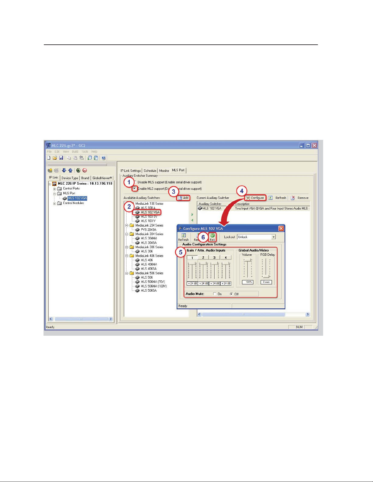
Software-based Confi guration and Control, cont’d
Confi guring an auxiliary switcher
An Extron MediaLink Switcher (MLS) or PoleVault switcher (PVS) can be
connected to the MLC to expand the number of inputs available to the projector/
display. However, if the MLS or PVS switcher is disabled, the MLS RS-232 port can
be used as an auxiliary, bidirectional RS-232 port, just like the Display port.
To enable and confi gure an auxiliary switcher, follow these steps:
1. In the Global Viewer MLS Port tab, select the Enable MLS Support radio
button. If the MLC and its attached MLS or PVS switcher are powered on and
connected to the network, GC automatically detects the switcher, and you can
skip to step 4. If not, proceed to step 2.
PRELIMINARY
2. Click on a switcher’s model name in the Available Auxiliary Switchers area.
3. Click the Add button.
4. Click the Configure button or double-click the switcher’s name in the Current
Auxiliary Switcher area. The Confi gure MLS modelname window appears.
5. Click and drag the slider bars to change the per-input audio input gain/
attenuation, the overall audio volume, and the RGB switching delay time.
Select Audio Mute On or Off.
6. Click Exit (at the top of the window) to return to GC, where you can continue
confi guring the MLC or save the project.
4-16
MLC 226 IP Series • Software-based Confi guration and Control
Page 61

Setting up passwords
1. Install and start the Extron Global Confi gurator (GC) software. See page 4-9.
2. Open an existing GC project or start a new project. Refer to the GC help fi le or
the MLC 226 IP Series Setup Guide for instructions.
3. Click Tools and select Change Device Settings from the drop-down menu.
4. In the Device Settings window, select (click on) the desired MLC in the list
that appears on screen.
5. Click Settings and choose Set Administrator
Password from the drop-down menu, as shown
at right. A Set for <IP address> window appears.
6. Type the Administrator password into both areas
of the window and click OK.
The Set for... window closes.
7. Click the Close button.
8. Complete the rest of the confi guration, then save the project: click File and
then Save or click the Save icon, shown below
9. Upload (build) the confi guration to the MLC. The Upload Manager window
appears, as shown below.
10. Click Exit after the fi les have been uploaded.
PRELIMINARY
MLC 226 IP Series • Software-based Confi guration and Control
4-17
Page 62

PRELIMINARY
Software-based Confi guration and Control, cont’d
Printing a wiring block diagram
Once you have confi gured a system using Global Confi gurator, you can generate
and print a simple block diagram of what products to wire to which of the MLC’s
ports. The diagram includes model names, DIP switch settings for control modules,
and the type of communication (IR or RS-232) confi gured for each port.
N
1. In Global Confi gurator, click on the File drop-down menu and select Print
2. Click on the check boxes to
3. Click the Print button at
4. Print the diagram(s), save the
5. In the Global Confi gurator Print Wiring Diagrams window, click Close.
This procedure requires Microsoft
provide that software. It is not an Extron product.
and then Wiring Diagram, as shown below.
A Print Wiring Diagrams
window appears, as shown at
right.
select one or more devices for
which to generate diagrams.
Or click the Select All button
to select all of the listed
devices.
the bottom of the window.
Global Confi gurator
processes the information
about the selected device(s),
generates a document
containing the wiring
diagram, and opens that
document in Word.
fi le, if desired, and exit Word.
®
Word software. The installer or user must
4-18
Updating fi rmware
If the need arises, you can replace the MLC 226 IP’s fi rmware without opening
the unit or changing fi rmware chips. See appendix B, “Firmware Updates”, for
instructions on how to update the controller’s fi rmware.
N
Save the existing confi guration project before replacing the fi rmware.
Saving and uploading the confi guration
This is not an advanced confi guration function, but when you fi nish creating the
confi guration in Global Confi gurator, you must save the GC project and upload
the confi guration to one or more MLC units. See chapter 3 of the MLC 226 IP Series
Setup Guide (shipped with the MLC) for instructions.
MLC 226 IP Series • Software-based Confi guration and Control
Page 63

Controlling the MLC
You can control the MLC and devices connected to it by using the MLC’s factoryembedded Web pages or its GlobalViewer (GV) Web pages that were created when
you uploaded the GC confi guration or a customized graphical user interface (GUI).
Embedded Web pages
The MLC 226 IP features an embedded Web server, which includes factory set Web
pages. These pages can be replaced with user-designed fi les, but the default Web
pages provide many basic features for monitoring, confi guring, and controlling
the MLC via a Web browser. These Web pages provide some of the features of the
confi guration program. This section provides an overview of the embedded Web
pages.
To access the embedded Web pages,
1. Launch a Web browser (Internet Explorer, Netscape Navigator, Mozilla
Firefox) on the connected PC, and enter the MLC’s IP address in the address
fi eld.
2. In the Enter Network Password dialog
box, shown at right, enter the MLC’s IP
address or text of your choice in the User
Name fi eld, type in the administrator
password in the Password fi eld, and click
OK. The MLC 226 IP’s default Web page
appears.
N
N
Passwords must contain 4 to 12
alphanumeric characters. Symbols
and spaces are not allowed, and the
passwords are case sensitive.
Administrators have access to all of the Web pages and are able to make
changes to settings. Users can access the System Status and Control: User
Mode pages only.
PRELIMINARY
MLC 226 IP Series • Software-based Confi guration and Control
4-19
Page 64

Software-based Confi guration and Control, cont’d
Status
These Web pages provide only settings information. Changes must be made
via the Configuration Web page or via the Global Confi gurator software or SIS
programming. Personnel who have user access can view these pages but do not
have access to confi guration pages.
System Status
The System Status page provides information about the MLC’s model, part
number, fi rmware level, voltages and internal temperatures, port and IP settings,
and the status of projector lamp hours and the display connection, as shown in the
following example. This information is useful when troubleshooting problems.
PRELIMINARY
N
Projector lamp hours are a refl ection of time elapsed since the lamp was changed
as determined by the driver/events associated with the MLC’s Display RS-232/
IR port.
4-20
MLC 226 IP Series • Software-based Confi guration and Control
Page 65
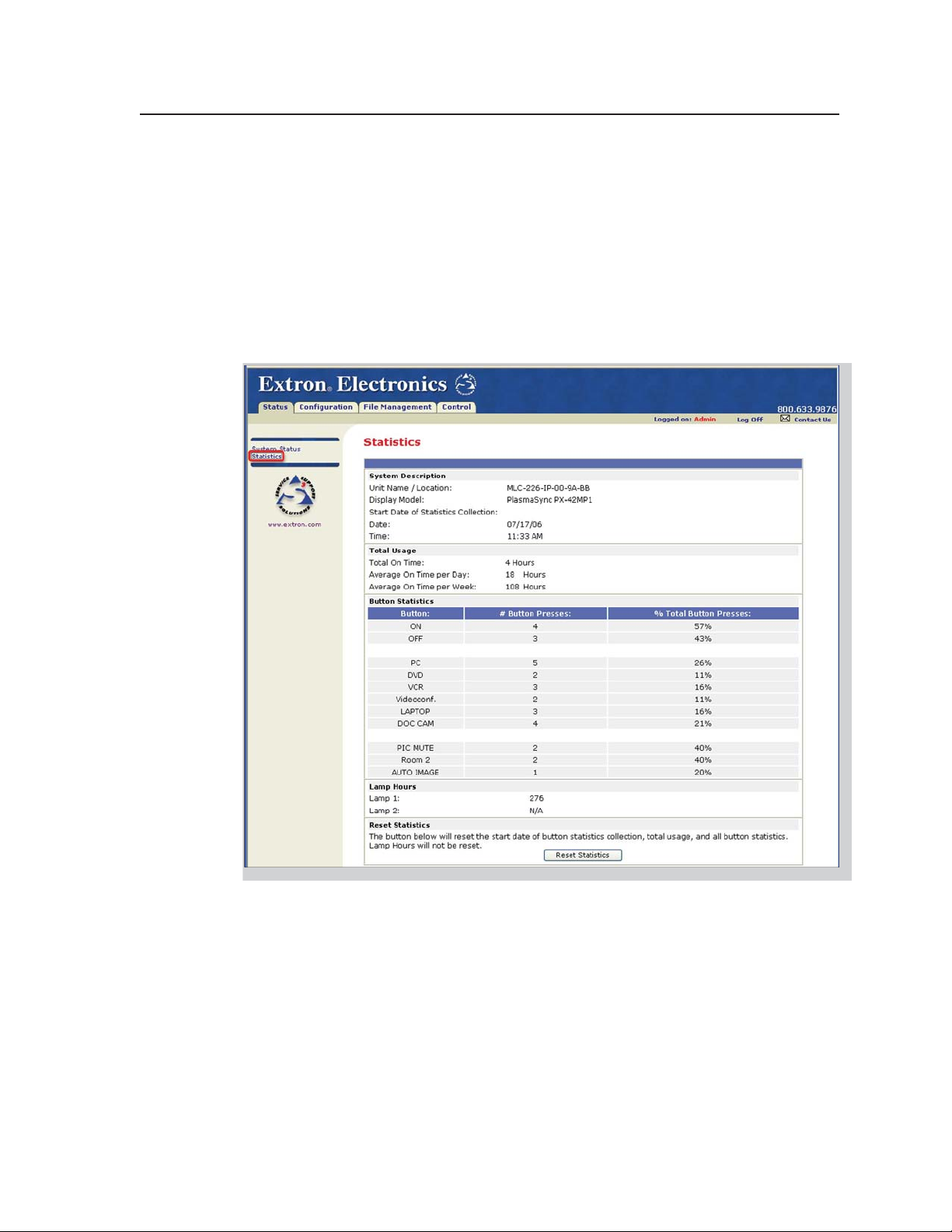
Statistics
The Statistics page is mainly for administrators and maintenance personnel. It
shows information about system usage: the number of hours the system has been
turned on, how many hours the projector lamp has been used, how much time per
day and per week the system is turned on, and how many times each button on the
MLC has been pressed, either physically or virtually (via confi guration software,
SIS commands, or event scripts). All of the button press and system use statistics
(with the exception of lamp hours) can be reset to 0 by clicking the Reset Statistics
button at the bottom of this screen.
N
This page is not available unless the MLC has been confi gured with Global
Confi gurator ver. 2.x or higher.
PRELIMINARY
MLC 226 IP Series • Software-based Confi guration and Control
4-21
Page 66

Software-based Confi guration and Control, cont’d
Confi guration
There are four Confi guration Web pages, which only administrators can access:
• System Settings for IP, date/time, and executive mode (front panel lockout)
setting changes
PRELIMINARY
N
Unit Name is any name (e.g., Room107MLC226IP, Lab1234mlc226IP,
ConfRoomSystem, LectureHall8-cntrlr) you use to label this specifi c MLC. The
default is a combination of the product name and part of the hardware address.
This can be changed to your choice of alphanumeric characters and hyphens (-).
• Spaces ( ) and underscores (_) are not permitted within a unit’s name.
• Valid characters are A-Z, a-z, 0-9, and - (hyphen).
• The name cannot start with a number or hyphen. It cannot end with a hyphen.
• Maximum name length is 24 characters.
4-22
MLC 226 IP Series • Software-based Confi guration and Control
Page 67

• Passwords, where you can change the administrator and/or user passwords
N
• Email Alerts, in which you can specify the Web server’s IP address and domain
N
Passwords must contain 4 to 12 alphanumeric characters. Symbols and
spaces are not allowed, and the passwords are case sensitive. A minimum of 4
characters are required when creating passwords via the Web pages.
name, set up SMTP verifi cation credentials, and specify e-mail alert recipients’
addresses and which e-mail fi le they will be sent
The MLC must fi rst be confi gured with Global Confi gurator before e-mail
addresses and e-mail fi le names appear on this page.
PRELIMINARY
MLC 226 IP Series • Software-based Confi guration and Control
4-23
Page 68
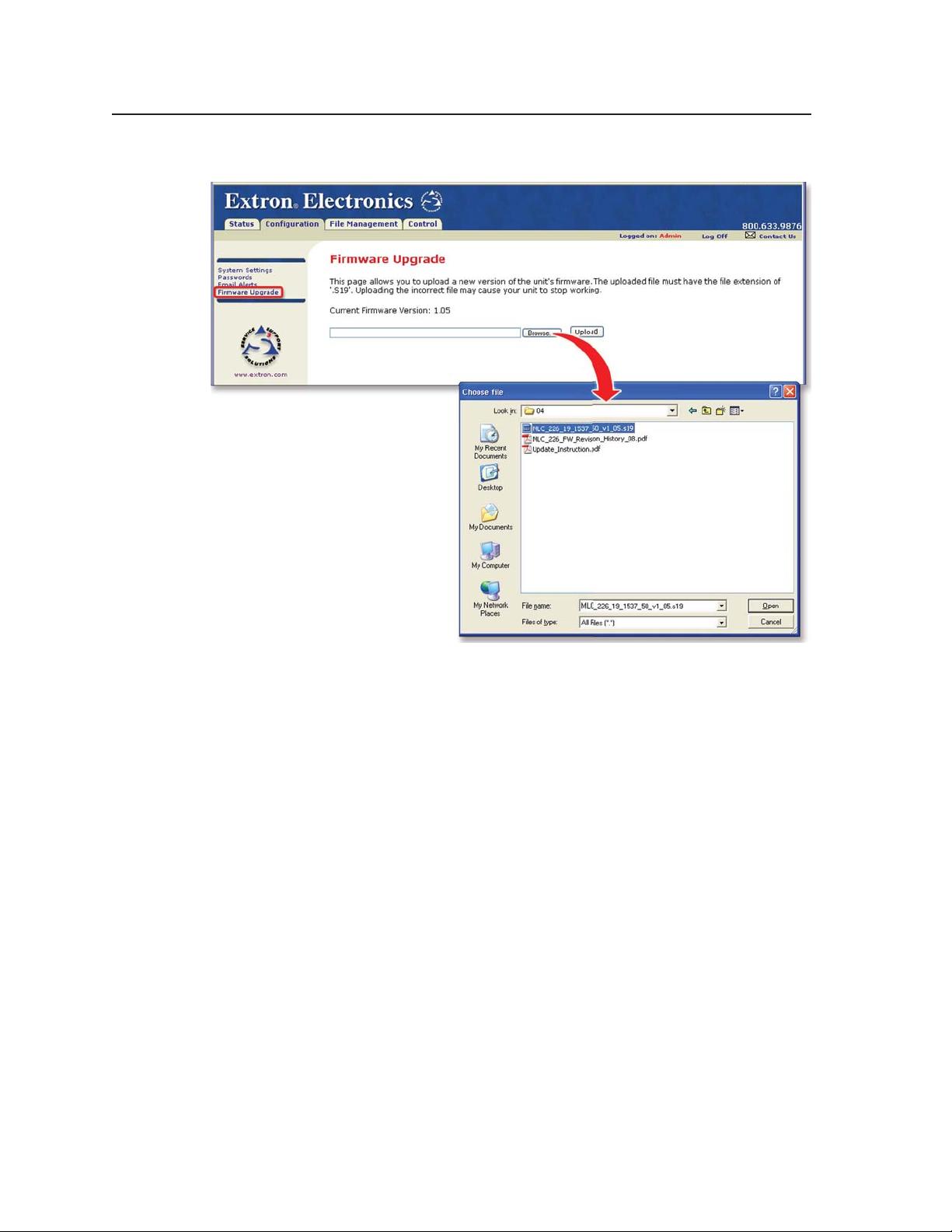
Software-based Confi guration and Control, cont’d
• Firmware Upgrade, through which you can locate and load new fi rmware to the unit
PRELIMINARY
N
N
File Management
This Web page allows you to sort by fi le type (see the Filter by File Extension
drop-down box). Personnel with administrator access can view these pages and
make changes. Those with user-level privileges are not able to see this page. See
appendix A for an explanation of fi le types.
See appendix B, “Firmware Updates,” for instructions on how to update the
controller’s fi rmware.
Save the existing confi guration project before replacing the fi rmware.
4-24
MLC 226 IP Series • Software-based Confi guration and Control
Page 69
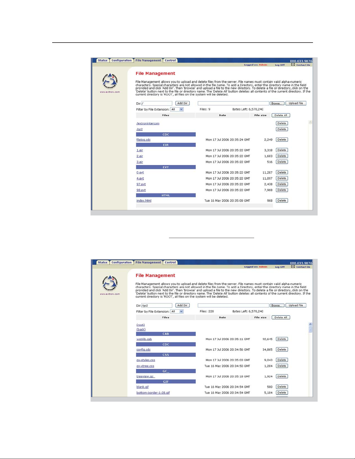
C
C
You can also view fi les in subfolders, including those containing GlobalViewer fi les
or IP Intercom fi les, if they have been installed on the MLC.
____. cdc fi les should NOT be deleted.
Event fi les should NOT be deleted. They are necessary for the controller’s
operation. Never delete the main event fi le (0.evt).
PRELIMINARY
MLC 226 IP Series • Software-based Confi guration and Control
4-25
Page 70

Software-based Confi guration and Control, cont’d
Control
• User Mode — The fi rst of the Control Web pages is User Mode, which is a
representation of the controller’s front panel buttons, volume control, and any
optional control modules (IRCMs, RCMs, ACMs) that are part of the system.
Clicking on a button on screen emulates a button press on the corresponding
device. This page is accessible to both administrators and users.
From the factory, the MLC 226 IP comes with a preloaded Web page with a basic
representation of the MLC 226’s front panel controls and the buttons of any
optional attached control modules. See the example below.
PRELIMINARY
Typical User Mode page
Web pages that show a more
lifelike representation of the
MLC’s front panel and of control
modules (as shown at right) are
included with the confi guration
software. These pages (over 200
fi les) can be uploaded into the
MLC if you select Upload
Enhanced Web Pages from the
Advanced Configuration page
in Global Confi gurator before
you build the confi guration and
load it into the MLC.
Enhanced User Mode page
4-26
MLC 226 IP Series • Software-based Confi guration and Control
Page 71

• IR Drivers — This Web page lists IR driver fi les only and allows you to select a
fi le to see and execute the commands stored in them. This page is available only
to those logged in with administrator level access.
N
An example for a specifi c IR driver is shown below.
The MLC must fi rst be confi gured with Global Confi gurator before this page can
be used.
• Serial Devices’ Drivers — Once the ports have been set up in the confi guration
program, each confi gured serial port (projector control port and any IR/Serial
control ports) is listed in this section of the Control page
menu.
Click on a port name to bring up a page that shows the
available commands for the device cabled to that port. See
the sample screen shots on the next page.
If you want to execute a command that is available in the driver (whether
associated with an MLC button or not) for a confi gured device, you can click on a
button or select an option from a pull-down menu to execute that command.
N
You must use Microsoft Internet Explorer version 6.0 or higher with Active X
enabled in order to use the serial devices’ control pages.
PRELIMINARY
MLC 226 IP Series • Software-based Confi guration and Control
4-27
Page 72

Software-based Confi guration and Control, cont’d
PRELIMINARY
Example of a page for an RS-232 controlled teleconferencing unit
connected to the MLC’s IR/Serial Out port B
4-28
Example of a page for a projector driver
MLC 226 IP Series • Software-based Confi guration and Control
Page 73

GlobalViewer™ Web Pages
The MLC 226 IP controller can be used as part of a network of devices based on
Extron IP Link™ technology, such as IP Link interfaces. Global Confi gurator (GC) is
a Windows-based program used for confi guring and customizing the Web browserbased GlobalViewer (GV) application for each IP Link interface, System 5 IP,
MLC 226 IP, MLC 104 IP Plus, or other IP Link-based device on a network. Once an
MLC 226 IP is confi gured, its GlobalViewer Web pages allow the user to manage,
monitor, and control the MLC and the devices connected to it.
Refer to the Global Confi gurator help fi le and the MLC 226 IP Series Setup Guide for
specifi c information on how to use the software and perform basic setup tasks for an
MLC 226 IP.
N
N
Four screens for the MLC are available via Global Viewer: Control, Monitor,
Schedule, and Info (
are described on the following pages.
To work with Global Viewer Web pages, you must use Microsoft Internet Explorer
version 6.0 or higher with Active X enabled.
If the MLC has been confi gured with passwords, the GlobalViewer Web pages are
password protected. Although default embedded Web pages are accessible via the
GlobalViewer Web pages, nonadministrators (people with only user access) are
able to access the Control and Status pages only.
). These screens
PRELIMINARY
MLC 226 IP Series • Software-based Confi guration and Control
4-29
Page 74

Software-based Confi guration and Control, cont’d
Control
PRELIMINARY
A typical GlobalViewer Control page
• The GlobalViewer tree view area at the left of the screen displays a list of other
IP Link-based devices in the same network that have GlobalViewer Web pages
installed. Listed beneath each device are any connected devices that can be
remotely controlled or monitored.
• The larger Control window on the right side of the screen functions just like
the Control embedded Web page. It provides buttons that correspond to those
on the MLC’s front panel, volume control, and additional buttons that let you
execute any command uploaded for each connected and confi gured device (the
projector/display and input devices).
4-30
MLC 226 IP Series • Software-based Confi guration and Control
Page 75

Monitor
A typical GlobalViewer Monitor page
• The Monitor window on the right side of the screen displays information
on what things (projector disconnection, lamp hours, and the like) are being
monitored, under what conditions, and who will receive an e-mail notifi cation
about each condition. This information appears only if the MLC 226 IP has been
confi gured to monitor such conditions.
PRELIMINARY
MLC 226 IP Series • Software-based Confi guration and Control
4-31
Page 76
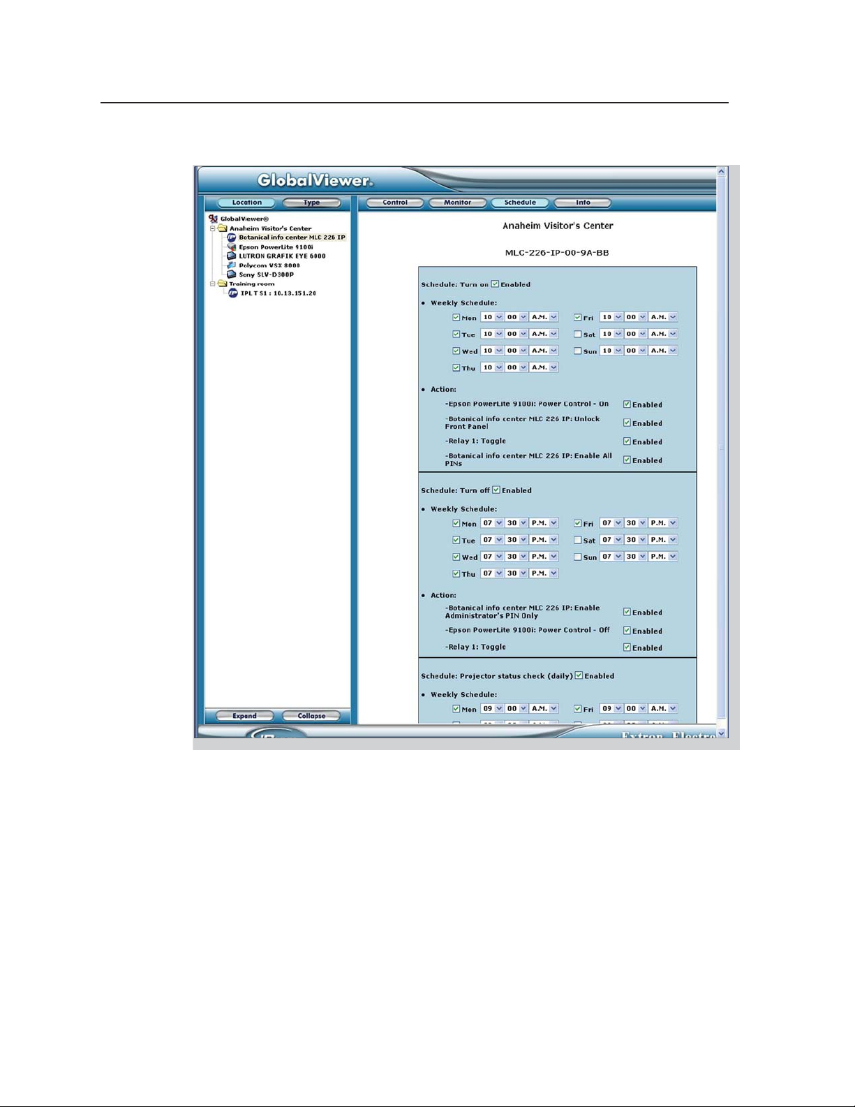
Software-based Confi guration and Control, cont’d
Schedule
PRELIMINARY
A typical GlobalViewer Schedule page
• The Schedule window on the right side of the screen displays and allows you
to change (if you are logged in as an administrator) the times the projector or
panel display is automatically powered down each day, and also the times when
the MLC’s front panel controls are locked and unlocked. You can also see what
actions are associated with each schedule and to enable or disable each action.
4-32
MLC 226 IP Series • Software-based Confi guration and Control
Page 77

Info
N
A GlobalViewer Info page showing a disconnected projector
To view the Info page, you must click on the location folder (in the GlobalViewer
area on the left of the screen) rather than on the MLC’s device name.
A GlobalViewer Info page showing a connected projector and other
equipment
PRELIMINARY
MLC 226 IP Series • Software-based Confi guration and Control
4-33
Page 78

Software-based Confi guration and Control, cont’d
•
The GlobalViewer tree area at the left of the screen shows a list of IP Link-based
devices within the network that have GlobalViewer Web pages
• The larger Info window on the right side of the screen displays basic information
about the MLC 226 IP, its IP settings, fi rmware version, attached devices,
display/projector (or other device) connection status, display power status, and
elapsed projector lamp hours.
• Projector or display power connection status is indicated by one of two icons:
connected (
MLC 226 IP obtains by power polling the display.
• The Power Status column indicates whether the projector/display is on, off,
warming up, cooling down, or unavailable (either because the projector is
disconnected or because it does not support power polling).
) or disconnected ( ). This status refl ects information the
Customizing the MLC’s Control Web Pages
Extron offers Web page templates that can be customized using standard HTML
editing tools to provide a different interface to the customer while still using
GlobalViewer functions. An experienced Web developer can add images, modify
text, and change background colors to create a look and feel that refl ects your brand
or your user’s specifi c requirements. For example, a university with dozens of
devices and rooms to control may wish to create customized Web pages with the
university’s school colors and logo. End users can control the system using these
customized pages instead of the standard GV pages.
Alternatively, Extron can create a customized graphical user interface (GUI) for you
to upload to each MLC in the system. End users can view the Web pages of this
customized GUI while administrators and installers still have access to the factoryset Web pages and the standard GV Web pages in addition to the customized ones.
For a small, one-time fee, Extron will turn the following items into fi les ready to
upload to the MLCs:
installed.
PRELIMINARY
• your Global Viewer project fi le containing system confi guration details
• your choice of available color schemes
• your choice of labels for panel buttons
• a company or institution logo
These customized Web pages, whether created by Extron or modifi ed by an outside
HTML developer from Extron-supplied templates, can also include button sets for
any control modules (IRCMs, ACMs, RCMs, CMs, etc.) used in the system.
Visit the Extron Web site (http://www.extron.com/product/archive.asp?id=customguifp)
or contact an Extron customer support representative for more information on this
service and on available template options.
4-34
MLC 226 IP Series • Software-based Confi guration and Control
Page 79

MLC 226 IP Series
Chapter Five
5
SIS™ Programming and Control
Host-to-MLC Communications
Commands and Responses
PRELIMINARY
Page 80

SIS™ Programming and Control
The MLC 226 IP Series controller can be remotely set up and controlled via a host
computer or other device (such as a control system) attached to the rear panel
Confi g/RS-232 port or LAN port, or the front panel Confi g port.
The MLC 226 IP must be confi gured before use. As shipped the controller can
trigger basic input switching on an optional MLS switcher, but it cannot control any
other devices before being confi gured.
The MLC 226 IP can be set up and controlled by using Extron’s Simple Instruction
Set (SIS) commands or the Extron Global Confi gurator software (version 2.2 or
higher), and both of those methods can be accessed via RS-232 or Ethernet LAN
connection. See chapter 2, “Installation,” for pin assignments and other details on
the confi guration and control ports. For information on the software and the MLC
226 IP’s embedded Web pages, see chapter four.
MLC 226 IP’s RS-232 protocol:
• 38400 baud
• 8 data bits
• 1 stop bit
• no parity
• no fl ow control
PRELIMINARY
N
LAN port defaults:
• MLC’s IP address: 192.168.254.254
• gateway’s IP address: 0.0.0.0
• subnet mask: 255.255.0.0
• DHCP: off
Both confi guration ports require 38400 baud communication. This is a higher
speed than many other Extron products use. The Global Confi gurator (version
2.2 or higher) software automatically sets the connection for the appropriate
speed. If using HyperTerminal or a similar application, make sure the PC or
control system connected to these ports is set for 38400 baud.
Host-to-MLC Communications
SIS commands consist of one or more characters per fi eld. No special characters
are required to begin or end a command sequence. When the MLC determines
that a command is valid, it executes the command and sends a response to the host
device. All responses from the MLC to the host end with a carriage return and
a line feed (CR/LF = ]), which signals the end of the response character string.
A string is one or more characters.
MLC-initiated messages
If you are communicating with the MLC 226 IP via RS-232 or via a verbose Telnet
connection, when a local event such as a front panel selection or adjustment takes
place, the MLC responds by sending a message to the host. No response is required
from the host. The MLC-initiated messages are listed here (underlined).
X!]
Chn
The unit sends this response when an input is switched.
(c) Copyright 2006, Extron Electronics, MLC 226 IP, Vx.xx, 60-600-00
Day, DD Mon YYYY HH:MM:SS
Vx.xx is the fi rmware version number.
The MLC sends the boot and copyright messages under the following
circumstances:
(where X! is the input number)
]
5-2
MLC 226 IP Series • SIS Programming and Control
Page 81

• If the MLC is off and an RS-232 connection is already set up (the PC is cabled
to the MLC and a serial terminal emulation program such as HyperTerminal
is open), the connected unit sends these messages via RS-232 when it is fi rst
powered on.
• If the MLC is on, it sends the boot and copyright messages when you fi rst open
a Telnet connection to the MLC. You can see the day of the week, date, and time
if the MLC is connected via Telnet, but not via RS-232. If you are using a Telnet
connection, the copyright message, date, and time are followed by a password
prompt.
Additional messages may be sent by the MLC in response to front panel selections
and volume adjustments and when scripts are executed during scheduled events.
Password information
The “]Password:” prompt requires a password (administrator level or user level)
followed by a carriage return. The prompt is repeated if the correct password is not
entered.
If the correct password is entered, the unit responds with “
or “]Login User]”, depending on the password entered. If passwords are the same
for both administrator and user, the unit will default to administrator privileges.
]
Login Administrator ]”
Error responses
When the MLC 226 IP receives a valid SIS command, it executes the command and
sends a response to the host device. If the MLC is unable to execute the command
because the command is invalid or it contains invalid parameters, it returns an
error response to the host.
The error response codes and their descriptions are as follows:
E01 – Invalid input channel number (the number is too large)
E12 – Invalid port number
E13 – Invalid value (the number is out of range/too large)
E14 – Not valid for this confi guration
E17 – System timed out
E22 – Busy
E24 – Privilege violation
E25 – Device is not present
E26 – Maximum number of connections has been exceeded
E27 – Invalid event number
E28 – Bad fi lename or fi le not found
E30 – Hardware failure (followed by a colon and a descriptor number) (This is an
unsolicited response.)
Error response references
The following superscripted numbers are used within the command descriptions
on the following pages to identify commands that may respond as shown:
14
= Commands that give an E14 (not valid for this confi guration) response if the
unit’s current confi guration doesn’t support that command.
22
= Commands that yield an E22 (busy) response.
24
= Commands that give an E24 (privilege violation) response if you are not logged
in at the administrator level.
27
= Commands that may yield an E27 (invalid event number) response.
28
= Commands that may give an E28 (fi le not found) response.
PRELIMINARY
MLC 226 IP Series • SIS Programming and Control
5-3
Page 82
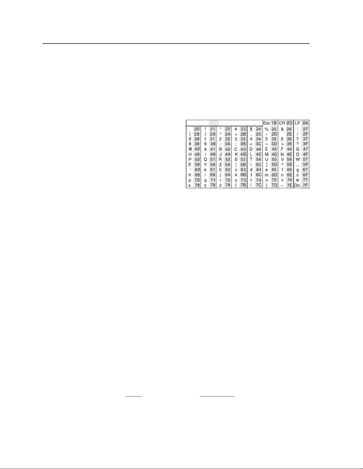
SIS™ Programming and Control, cont’d
Commands and Responses
Using the command/response tables
The MLC 226 IP can be controlled via either a Telnet (port 23) or RS-232 connection
using ASCII commands. Or it can be controlled via a Web browser (port 80)
connection using URL-encoded commands. The ASCII and URL commands listed
in the tables starting on page 5-8 perform the same functions, but they are encoded
differently to accommodate the requirements of each port (Telnet or browser).
The ASCII to hexadecimal
(HEX) conversion table shown
at right is for use with the
command/response tables.
The command/response tables list valid ASCII (for Telnet or RS-232) command
codes, the corresponding URL (uniform resource locator) encoded (for Web
browsers) command codes, the MLC 226 IP’s responses to the host, and a
description of the command’s function or the results of executing the command.
ASCII to Hex Conversion Table
ASCII to Hex conversion table
•
PRELIMINARY
• Upper and lower case characters may be used interchangeably in the command
fi eld unless otherwise specifi ed.
• Commands may be sent back-to-back without spaces (for example, 2!65V1Z).
• Numbers can be entered as 1, 2, or 3 digits, e.g., 8V = 08V = 008V.
• There are a few differences in how to enter the commands depending on whether
you are using Telnet or a Web browser.
• When using these commands through a Web browser, the URL reference
is used to shorten the examples. “URL” refers to the full URL of the
control interface and Web page reference including all path information
(e.g., http://192.168.100.10/myform.htm).
• To send any of the commands using a Web browser you must prefi x them
with the full URL followed by ?cmd=.
• For control via a Web browser, all non-alphanumeric characters must be
represented as the hexadecimal equivalent, %xx, where xx represents the
two-character hex byte. A comma (,), for example, would be represented
as %2C.
Characters such as %, +, and the space character ( ) must be encoded as
hex bytes, or they will be misinterpreted by the MLC. For example, the
ASCII command +V must be encoded as %2BV for Web browser use.
• Some characters differ depending on the method you use to send the
commands:
Telnet Web browser
Escape (hex 1B) W [must not be hex encoded]
Carriage return (hex 0D) Pipe character (
|
) [must not be hex encoded]
5-4
MLC 226 IP Series • SIS Programming and Control
Page 83

Symbol defi nitions
]
= CR/LF (carriage return/line feed) (hex 0D 0A)
}
= Carriage return (no line feed, hex 0D)
(For URL-encoded commands, use the
pipe character,
• = Space character
|
= Pipe (vertical bar) character
E
= Escape key (hex 1B)
(Use W instead of Esc for Web browsers.)
X!
= Specifi c port number or relay number (01 – 99)
X@
= Command data section.
N
X#
= Greenwich Mean Time (GMT) offset value
X%
= On/off status
X*
= Volume level (0 – 100 steps). The maximum
X1!
Relays:
1 = relay 1, 2 = relay 2, 3 = relay 3,
4 = relay 4, 5 = relay 5, 6 = relay 6
Other ports:
1 = rear host (Confi g/RS-232 port)
2 = front panel Confi g port
3 = slaved switcher (MLS port)
4 = display/projector port
(Proj RS-232/IR)
5 = IR/Serial port A
6 = IR/Serial port B
7 = IR/Serial port C
For Web encoding only: data is directed to
the specifi ed port and must be encoded (URL
encoding) if it is non-alphanumeric. Change
any non-alphanumeric character (%, +,
|, }
, etc.) within the data section into the
corresponding hexadecimal equivalent, %xx,
where xx represents the two-character hex byte.
For example, a space (hex: 20) would be encoded
as %20 (hex: 25 32 30) and a plus sign (hex: 2B)
would be encoded as %2B or hex 25 32 42.
(-12.00 to +14.00) represents the time
difference in hours and minutes
(+/-hh:mm) relative to Greenwich,
England. The leading zero is optional.
For example, 5:30 = 05:30. Do not use a
plus (+) sign if the GMT offset is positive.
0 = off/disable
1 = on/enable
volume level is limited by the max.
volume range command (
Default volume = 25.
= Version (typically listed to two decimal
places, e.g., x.xx)
N
With Telnet you can use either an “Escape” (
E
) command or a “W”
command, and the carriage return or the pipe character. With the Web browser,
you are required to use a “W” command and the pipe character.
In either method, {Data} = data that will be directed to a specifi ed port
and must be hex encoded if non-alphanumeric.
N
If you make adjustments (changes to volume, etc.), whether via the front panel
or via RS-232 or IP communication, it will take 1 minute 40 seconds (100
seconds) for the data in the MLC 226 IP’s RAM to be saved to fl ash memory.
X1@
= MLC’s name. The name is a text string of up
to 24 characters drawn from the alphabet
(A-Z), digits (0-9), and minus sign/
|
, instead.)
X?
X1#
Set format (MM/DD/YY-HH:MM:SS).
Read format (day of week, date month year
X1$
X1%
X1&
N
X1*
X1(
X2)
*47#).
N
hyphen (-). No blank or space characters
are permitted as part of a name. No
distinction is made between upper and
lower case. The fi rst character must be
a letter. The last character must not be a
minus sign/hyphen.
= Local date and time format
Example: 01/18/05-10:54:00.
HH:MM:SS). Example: Tue, 18 Jan 2005
18:19:33.
= IP address (xxx.xxx.xxx.xxx). Leading zeros
in each of four fi elds are optional in
setting values, and they are suppressed in
returned values.
MLC’s default address: 192.168.254.254
Default broadcast address:
255.255.255.255.
= E-mail domain name; for example, extron.com
= Time in tens of milliseconds to wait until the
fi rst response character is received via a
serial port before terminating the current
receive operation (Default = 10 = 100 ms,
max. = 32767.) The response includes
leading zeros.
For commands that use both
variables must be zero or both must be non-zero.
In the RS (send data) command,
as long as
= Hardware (MAC) address (xx-xx-xx-xx-xx-xx)
= Subnet mask (xxx.xxx.xxx.xxx). Leading
= Time in tens of milliseconds to wait between
For commands that use both
variables must be zero or both must be non-zero.
In the RS (send data) command,
as long as
X2)
is also missing.
(00-05-A6-xx-xx-xx)
zeros are optional in setting values in each
of four fi elds, and they are suppressed in
returned values. Default = 255.255.0.0.
characters being received via a serial port
before terminating the current command
or receive operation. The response
includes leading zeros.
(Default = 2 = 20 ms, max. = 32767)
X2)
is also missing.
X1&
X1&
and
X1&
is optional
and
X1&
is optional
X2)
X2)
PRELIMINARY
, both
, both
MLC 226 IP Series • SIS Programming and Control
5-5
Page 84

SIS™ Programming and Control, cont’d
PRELIMINARY
X2!
= Parameter (#L or #D) to set either the Length
of message to receive or the Delimiter
value. # = byte count (for L) or
# = a single ASCII character expressed in
decimal form (for D).
The parameter is case sensitive; you must
use capital D or capital L.
Byte count # can be from 0 to 32767,
default = 0.
The ASCII decimal # can be from 0 to
00255, default = 00000L.
Examples:
X2@
N
X2#
X2%
X2^
X2&
X2*
X3#
N
X3$
A 3-byte length = 3L.
A delimiter of ASCII 0A = 10D.
The response from the MLC includes
leading zeros.
= Verbose/response mode status:
0 = clear/none, default for Telnet
connections; responses are not echoed to
the host
1 = verbose mode is on, default for RS-232
host control; responses are echoed to the
host and displayed to the user
2 = send tagged responses for queries
3 = verbose mode is on and tagged
responses are sent for queries
If tagged responses are enabled, all read
commands return the constant string + data,
the same as for setting a value. For example,
E
CN }, the response is Ipn•
for
rather than just the data.
= Priority status for receiving timeouts:
0 = use send data string command
parameters (0 = default)
1 = use confi gure receive timeout command
parameters
= Baud rate: 300, 600, 1200, 1800, 2400, 3600,
4800, 7200, 9600, 14400, 19200, 28800,
38400, 57600, or 115200
= Parity (only the fi rst letter is needed):
Odd
Even
None (default)
Mark
Space
= Data bits: 7, 8 (default = 8)
= Stop bits: 1, 2 (default = 1)
= Password (minimum length = 4 characters,
maximum length = 12 characters,
no special characters are allowed)
A user password cannot be assigned if no
administrator password exists; the E14 error
code will be returned. If the administrator
password is cleared, then the user password is
also removed.
= Daylight saving time (DST) is a region-
specifi c 1-hour offset that begins in spring
and ends in fall.
0 = off/ignore
1 = USA on – traditionally starts on the
fi rst Sunday of April at 2 am and ends at
2 am on the last Sunday of October. For
example, time in California is GMT -8:00
from April to October and GMT -7:00
from November to March. However, in
2007 DST starts on the second Sunday
X1@ ]
in March and ends the fi rst Sunday in
November. DST should be turned off in
Hawaii, American Samoa, Guam, Puerto
Rico, the Virgin Islands, the eastern time
zone portion of the state of Indiana, and
the state of Arizona (excluding the Navajo
Nation).
2 = Europe on – begins on the last Sunday
in March, ends on the last Sunday in
October. DST should be turned off for
Iceland.
X3%
= Event number, range = 0 - 99
(valid only while events are running)
X4)
= I/O mode
0 = input
1 = output (digital I/O on 9-pin D
connector only)
2 = input and pull-up resistor
(digital I/O on 9-pin D connector only)
3 = output and pull-up resistor (digital
I/O on 9-pin D connector only)
8 = power sensor digital input
X4!
= Password to display on screen (response to
password query or set). When the MLC
connects to a host device via RS-232, the
password (
When the connection is via IP,
asterisks (****) if a password has been
X4#
X4%
X4^
X4&
X4(
X5@
X5&
X5*
X5(
assigned, or it is an empty fi eld ( ) if a
password hasn’t been assigned.
= I/O state
0 = off
1 = on
= E-mail event number or mailbox (1 - 64). The
response is two digits with a leading zero.
= E-mail recipient’s address (e.g.,
JDoe@extron.com) for the person to whom
messages will be sent. The e-mail address
has a 31 character maximum.
= Name (numeral) of e-mail fi le to be sent
= Default name: a combination of the model
name and the last 3 pairs of the MLC’s
MAC address (e.g., MLC-226-IP-00-02-3D)
= Connection’s security level
11 = user
12 = administrator
= IR playback fi le number (0 to 99) (no
extension) The response includes leading
zeros.
= IR playback function number (1 to 137) The
response includes leading zeros. IR
function numbers 0 and 127 or higher can
return information only.
0 = return all data
129 = manufacturer
130 = model
131 = class
132 = remote
133 = creation date
134 = comments
137 = user fi le name (a descriptive name
the user/installer gave the fi le).
= IR playback mode
0 = play once
1 = play continuously
X3#
), itself, is the response.
X4!
is 4
5-6
MLC 226 IP Series • SIS Programming and Control
Page 85

X6#
= Pulse time in 20 ms per count. If this
parameter is missing or = 0, then pulse
length = default = 25 = 500 ms. 1 =
20 ms (minimum pulse time) to 65535 =
1310700 ms (maximum pulse time).
X6$
= Broadcast repetition interval in seconds
(0 to 255, default = 0 = off)
X6%
= Date and time returned in 7 hex bytes for
month, day, year, hour minutes, seconds,
day of the week (1 = Sunday, 7 = Saturday)
X6(
= IP connection timeout period in seconds.
Each step is specifi ed in 10-second
intervals (1 - 65000, default = 30 = 300
seconds). If no data is received during the
specifi ed period, the Ethernet connection
closes. Responses are returned with
leading zeros.
X7)
= The number to insert into an email message
if a ____.eml fi le has an embedded serverside include “<!--#echo var = “WCR
-->” (the
parameters.) The numeral is a 16-bit
number to be employed as the user
defi nes.
This is an optional parameter. Use 0 as a
placeholder if the optional
is used but
= 65535.
X7#
= An e-mail account username of up to 31
characters. Do not use commas. This
parameter is optional during setup and is
used for SMTP authentication.
X7$
= An e-mail account password (for SMTP
authentication) of up to 31 characters.
Do not use commas. This parameter is
optional during setup.
X20)
= Specifi c input number (1 – 6)
1 = input 1
2 = input 2
3 = input 3
4 = input 4
5 = input 5
6 = input 6
X20%
= Lamp hours elapsed (0 to 99999 hours)
The fi ve-digit response includes leading
zeros. The default is 99999 hours, which
yields an “N/A” response.
X20^
= Voltage (in volts)
X20&
= Temperature in degrees Celsius (the response
is 3 digits including leading zeros)
X20*
= Display (projector) power status
0 = display power is off
1 = display power is on
2 = display is powering down/off (cooling
down)
3 = display is powering up/on (warming
up)
X20(
= Front panel lockout (executive mode) status
0 = off/unlocked (default)
3 = on, disable/lock entire front panel
(buttons, volume control) and optional
connected SCP, control module(s), and IR
remote control
E
CR} command with no
X4&
X7)
is not needed. Maximum
|
”
variable
X21)
= IR/serial port confi guration
0 = IR ports (0 V – 5 V)
(default for IR/Serial Output ports A-C)
1 = RS-232 ports (±5 V)
(default for the Display RS-232/IR port)
X21!
= Status (in hexadecimal characters) of script
or fi rmware button control. This variable
is an 8-digit hexadecimal character
calculated from a binary bit map. It is
case-sensitive. Use capital letters. See
page 5-30 for details.
X21@
= Status (in hexadecimal characters) of control
of all button lights).
This variable is an 8-digit hexadecimal
character calculated from a binary bit
map, and it is case-sensitive. Use capital
letters. See page 5-32 for details.
X21#
= Power sensor status:
00 = power sensor is connected and is not
sensing projector power
01 = power sensor is connected and is
sensing projector power
02 = power sensor is disconnected or
sensor is connected but the sensitivity is
set too high
X21$
= Power sensor signal pin status
00 = voltage is low
01 = voltage is high
Leading zeros are used in responses to
commands that use this variable.
X21%
= IR/Serial Output port number
1 = projector/display port
2 = port A
3 = port B
4 = port C
X21^
= Display mute or connection status
0 = off/disconnected
1 = on/connected
2 = unknown/unavailable (default for
connection status)
X21&
= Firmware’s event status polling period from
0 to 255 in 20 ms increments.
optional: if it is not set, it defaults to
100 (2 seconds) and is not shown in the
command’s response. If
the fi rmware does not poll for event
status.
The event number that is polled is set by
N
X22#
the EN command.
= Digital I/O port (specifying which port)
1 = rear panel Host Control port (9-pin D
connector)
2 = Pwr Sns pin on the Display RS-232/IR
port
X21&
X21&
is
is set to 0,
X3%
PRELIMINARY
in
MLC 226 IP Series • SIS Programming and Control
5-7
Page 86

SIS™ Programming and Control, cont’d
= 1, 2, 3, 4, 5, 6)
X20)
(
PRELIMINARY
X20)
= The MLC responds with an E14 error
(audio and video).
code (invalid for this confi guration) if the
desired input is not set up to switch inputs
Additional description
Select input
14
]
(is not in input button mode). Events are
X20)
Response
(switcher to host)
%21 Chn
URL Encoded (Web)
(host to switcher)
X20)
= The MLC sends a “busy” response (E22)
still triggered, though.
if switching functions are locked.
22
On (discrete).
Off (discrete).
Show the display power status.
Example: the display is powering off.
This command is used only by scripts. It
provides a way to set the power status to
match the actual state of the projector.
X20*]
Pwr
X20*]
Pwr
]
X20*]
2
X20*]
%2A0P Pwr
X20*
, 0 = display power is off
X20*
1 = display power is on
2 = display is powering down/off
For
3 = display is powering on (warming up).
= 0 (off), 1 (on), or 2 (unknown).
X21^
Mute.
Unmute.
Show display mute status.
This command is used only by scripts. It
provides a way to set the status to match the
actual state of the projector.
]
X21^]
X21^]
X21^
X21^]
Mut
Mut
%2A0M Mut
X21^
!
(host to switcher)
Command/response table for SIS commands
Command ASCII (Telnet)
5-8
MLC 226 IP Series • SIS Programming and Control
X20)
14, 22
Select an input
Input selection
PP
Example:
Turn display power on 1P 1P
Turn display power off 0P 0P
Display (projector) power
View display power status P P
*0P
X20*
This command does not trigger the warm up/cool down (power on/power off) sequences or the button’s events.
N
Set power status
commands to function.
The 1M and 0M commands emulate the IR 402’s Display Mute On and Display Mute Off buttons. You must program these buttons on the remote for the 1M and 0M
N
Display mute
Turn display mute on 1M 1M
Turn display mute off 0M 0M
View display mute status M M
*0M
X21^
This command does not trigger button events.
N
Set mute status
Page 87
*47#).
X?
= 1-6, to
X!
on.
off.
X!
X!
on/off.
X!
= volume level (0 to 100). Default
Additional description
This command sets a specifi c volume level
for the audio output at either the display
device or via an optional slaved Extron
MediaLink (MLS) switcher.
X*
volume = 25.
X*]
Response
(switcher to host)
URL Encoded (Web)
(host to switcher)
V Vol
X*
When no MLS is detected at the MLS port,
the maximum volume level is limited by the
max. volume range command (
Example: set volume to 27.
]
Vol027
Show the output volume.
Increase audio output.
Decrease audio output.
X*]
X*]
Vo l
Vo l
X*]
Increase audio output.
X*]
Vo l
Decrease audio output.
X*]
Vo l
Show the output volume.
X*]
Mute all audio outputs. This is not the same
as selecting input 0.
]
Amt1
= 0 (off) or 1 (on).
Unmute all audio outputs.
Show the status of audio mute.
X%
]
X%]
Amt0
Turn relay number
match the corresponding relay number.
Toggle relay
]
*0
X!
%2A0 O Rly
X!
X%]
*
X!
%2A2O Rly
X!
*1 Turn relay number
X!
%2A1 O Rly
X!
= 1 (on) or 0 (off).
X%
PRELIMINARY
(host to switcher)
Command/response table for SIS commands (continued)
Command ASCII (Telnet)
V
X*
14
Set the overall output volume
level
Volume adjustment (discrete, for volume mode = 0)
27V 27V
MLC is in increment/decrement volume mode (volume mode 1).
The MLC responds with an E14 (not valid for this confi guration) error if you attempt to set a discrete volume level while the
Example:
N
Increment the volume +V %2BV
Decrement the volume -V %2DV
The MLC responds with an E14 (not valid for this confi guration) error if you attempt to set a discrete volume level while the
View the volume level V V
N
Increment the volume +V %2BV
Volume adjustment (for volume mode = 1)
MLC 226 IP Series • SIS Programming and Control
MLC is in increment/decrement volume mode (volume mode 1).
Mute off 0Z 0Z
Decrement the volume -V %2DV
View the volume level V V
Mute on 1Z 1Z
Audio mute
View the audio mute status Z Z
Relay functions
*1O
X!
Force relay on
*0O
X!
Force relay off
*2O
X!
Toggle relay
5-9
Page 88
SIS™ Programming and Control, cont’d
) in
X6#
) relay’s pulse time (
X!
PRELIMINARY
20 ms increments from 1 (20 ms, minimum)
to 65535 (1310700 ms, maximum).
Additional description
Set a specifi c (
X%]
*
X!
Response
(switcher to host)
O Rly
Default pulse length is 25 = 500 ms.
X%]
*
X!
Rly
X%]
X6#
URL Encoded (Web)
%2A3%2A
(host to switcher)
X!
O
X!
= The MLC responds with an E24 error
(privilege violation) if the connected user is
Default setting. Adjustments and selections
can be made from the front panel in
addition to via RS-232, Telnet, or Web
]
Exe 0
not logged in at administrator security level.
browser.
24
Lock all front panel selections and
adjustments via MLC, control modules, SCP,
]
Exe 3
= 0 (off, unlocked) or 3 (front panels,
control modules, and remote control
and IR remote. Make selections, changes,
and confi gure features via RS-232 or Web/
Ethernet only. All front panels in the control
system are locked.
Show lockout (executive mode) status.
X20(
X20(]
locked/disabled).
Executive mode is off.
]
0
represents the number of elapsed
hours of projector lamp use. The MLC
responds with two sets of lamp hours only
if two lamp hours have been set. If a lamp’s
status has not been set, it is shown as the
default (99999 hours) or “N/A”.
X20%] X20%
*
X20%
or
X20%]
O
X6#
*3*
(host to switcher)
X!
Command/response table for SIS commands (continued)
5-10
Pulse relay
Command ASCII (Telnet)
MLC 226 IP Series • SIS Programming and Control
O
X!
original state.
If the verbose mode is enabled, there are two responses from the unit because the relay is pulsed. During a pulse, the relay is toggled to its opposite state and then back to the
N
View the relay state
0X 0X
24
Disable lockout modes
Front panel security lockout modes (executive modes)
3X 3X
24
Enable lockout mode 3
XX
Example:
View the lockout mode status X X
View lamp hours status 6S 6S
Status commands
Page 89

):
X21$
represents the fi ve-digit numeric
= The MLC responds with an E24 error
(privilege violation) if the connected user is
Additional description
value for elapsed lamp use hours, and it
is used by script to determine the number
sent in response to the “view lamp hours”
command (6S).
] X20%
not logged in at administrator security level.
24
X20%
Response
(switcher to host)
%2A 6S Lhr*
= 0 (disconnected), 1 (connected), or 2
This command lets you know whether
the MLC’s scripts have determined if the
X20%]
*
(unknown).
display is still connected to the MLC.
X21^
X20%
) used by scripts.
X21^
This command is used to reset the
0 = projector not connected.
projector/display connection status fl ag
(
X21^]
1 = projector is connected.
2 = undetermined status.
X21^]
%2A 6S Lhr*
X20%
%2A
%2A 7S Pcs
is as follows:
X21#
00 = power sensor is connected and is not
sensing projector power.
01 = power sensor is connected and sensing
projector power.
02 = sensor is disconnected or sensor is
connected but sensitivity is too high.
If the MLC is connected to an Extron Power
Sensor that monitors the projector/display,
this tells you whether the display is still
powered on.
X21#]
00 = voltage is low.
Power sensor signal pin status (
X21$]
= voltage in volts.
X20^
01 = voltage is high
The response includes leading zeros.
View all voltages and the MLC’s internal
temperature at once.
Display the operating voltage of the MLC’s
power input.
]
X20^]
responses from commands
12S•13S•14S•15S•16S•20S
+
PRELIMINARY
URL Encoded (Web)
(host to switcher)
X20%
*6S
(host to switcher)
X20%
24
Command/response table for SIS commands (continued)
Set lamp hours status for 1 lamp
Command ASCII (Telnet)
X20%
*6S
X20%
*
X20%
24
Set lamp hours status for 2 lamps
View connection status 7S 7S
X21^
*7S
X21^
24
Set display connection status
MLC 226 IP Series • SIS Programming and Control
View power sensor status 8S 8S
9S 9S
View power sensor signal pin
status
11S 11S
12S 12S
View all voltage and
temperature status
View +12 V power supply
voltage
5-11
Page 90

SIS™ Programming and Control, cont’d
= temperature in degrees Celsius (the
PRELIMINARY
Additional description
X20^]
Response
(switcher to host)
URL Encoded (Web)
(host to switcher)
X20^]
+
+
Display the operating voltage for the IR/
Serial and projector ports.
X20^]
X20^]
+
-
Display the internal operating temperature.
X20&
X20&]
response is 3 digits including leading zeros).
(host to switcher)
13S 13S
14S 14S
View +5 V IR receiver port
voltage
View +3.3 V IP Link/FPGA
voltage
View +1.5 V FPGA voltage 15S 15S
View -10 V IR/Serial bus voltage 16S 16S
Command/response table for SIS commands (continued)
Command ASCII (Telnet)
5-12
MLC 226 IP Series • SIS Programming and Control
View internal temperature status 20S 20S
Page 91

= specifi c port number (01 – 99)
1 = rear host (Host Control RS-232 port)
2 = front panel Confi g port
3 = slaved switcher (MLS port)
Additional description
4 = display port (Projector RS-232/IR)
]
| X@
Response
(switcher to host)
RS
response from command
X2!
%2A
X2)
%2A
X1&
%2A
} X@ X!
X!
RS
X2!
*
X2)
*
X1&
*
E X!
W
URL Encoded (Web)
(host to switcher)
(host to switcher)
= time in tens of ms for the MLC to wait
5 = IR/Serial port A
= command data section (< 200 bytes).
6 = IR/Serial port B
7 = IR/Serial port C
X@
X1&
until receipt of the fi rst response character
before terminating the current receive
operation (default = 10 = 100 ms, max. =
32767). The response includes leading zeros.
]
response from command
<data>
|
is also missing. If these three variables are not specifi ed, the
must both a) equal zero or b) be nonzero.
X2)
X2)
and
X1&
is optional only if
X1&
, convert nonalphanumeric characters to hex numbers. A space (hex = 20) is encoded as %20.
W05%2A4%2A7%2A3L RS
<data>
}
05*4*7*3L RS
E
X@
is optional.
X2!
*
X2)
*
X1&
*
A plus sign (hex = 2B) is encoded as %2B.
For Web encoding for
Example:
default values are used. For this command,
) in this RS command is limited to 200 bytes.
X@
The data string (
= time in tens of ms for the MLC to
X2)
wait between characters being received via
a serial port before terminating the current
receive operation (default = 2 = 20 ms,
= #L or #D. The letter parameter is case
max. = 32767). The response includes
leading zeros.
X2!
sensitive (requires a capital “D” or capital
“L”). The response includes leading zeros.
L = Length of the message to be received.
D = Delimiter value.
# = byte count (for L) or a single ASCII
ASCII to Decimal Conversion Table
To find the decimal equivalent of the ASCII character, add
the row heading and column heading numbers together.
0 1 2 3 4 5 6 7 8 9
10 LF CR
20 Esc
30 space ! “ # $ % & ’
40 ( ) * + , - . / 0 1
50 2 3 4 5 6 7 8 9 : ;
character expressed in decimal form (for D).
Byte count # can be from 0 to 32767, default
= 0. The ASCII decimal delimiter # value
can be from 0 to 00255, default = the byte
count.
Examples: A 3-byte length = 3L. A delimiter of
ASCII 0A = 10D.
})
LF = line feed
CR = carriage return (
Esc = escape
Del = delete
100 d e f g h i j k l m
110 n o p q r s t u v w
60 < = > ? @ A B C D E
70 F G H I J K L M N O
80 P Q R S T U V W X Y
90 Z [ \ ] ^ _ ‘ a b c
120 x y z { | } ~ Del
PRELIMINARY
N
These commands apply to any port that uses RS-232 communication: both 1-way (output) and 2-way (bidirectional) RS-232 communication.
Send data string
Command/response table for SIS commands (continued)
Command ASCII (Telnet)
Serial data port confi guration and use
N
N
MLC 226 IP Series • SIS Programming and Control
5-13
Page 92
SIS™ Programming and Control, cont’d
PRELIMINARY
.
X!
), data bits
X2^
) for port
X2*
), parity (
X2%
), and stop bits (
= 300, 600, 1200, 1800, 2400, 3600, 4800,
Additional description
X2&
Set baud rate (
X2%
(
|
CP
X2*
Response
(switcher to host)
%2C
= parity (only the fi rst letter is needed):
Odd
X2^
Even
7200, 9600, 14400, 19200, 28800, 38400, 57600,
or 115200 baud.
]
X2*
,
X2&
,
X2^
,
X2%
•Ccp
X!
Cpn
X2&
%2C
X2^
%2C
X2%
}
%2A
CP
X2*
,
X2&
,
X2^
,
X2%
*
E X!
24
X!
W
URL Encoded (Web)
(host to switcher)
(host to switcher)
= data bits: 7, 8 (default = 8).
None (default)
Mark
Space.
X2&
= waiting time in
X1&
= stop bits: 1, 2 (default = 1).
X2*
Set the projector control port for 9600 baud,
no parity, 8 data bits, and 1 stop bit.
Set the time to wait (
tens of ms until receipt of the fi rst response
character before terminating the receive
]
X2!
|
CE
X2!
%2A
X2#
X2)
X1&
X!
]
]
X2(
,
X2&
,
X2^
|
,
Cpn4•Ccp9600,N,8,1
X2#
%2A
X2)
%2A
X1&
}
| X2%
CP
%2A
CE
X!
X!
X2!
W4%2A9600%2CN%2C8%2C1CP
}
4*9600,N,8,1CP
E
W
}
CP
E X!
*
X2#
*
X2)
*
X1&
*
E X!
W
= waiting time in
X2)
: 0 = default, use send data string
X2#
tens of ms between characters before
operation,
,
,
,
•Cce
Cpn
command parameters; 1 = use confi gure
terminating) and priority status
(
= #L or #D (see previous page).
X2!
.
X!
receive timeout command parameters) for
port
The response includes leading zeros.
]
X2!
X2#
X2)
X1&
|
X!
}
E X!
= IR
X5*
= IR playback
X5(
(1 = display port, 2 =
X21%
= the IR fi le number (0-99),
Send an IR command via IR/Serial Output
port number
X5&
port A, 3 = port B, 4 = port C).
mode (0 = play once, 1 = play continuously).
function number (1-137),
) = 0. Also, the response includes leading zeros.
X5(
]
,
,
,
|
IR
X5(
%2C
X5(
,
X5*
,
X5&
,
X21%
Irs
X5*
%2C
X5&
}
IR
X5(
,
X5*
,
X5&
,
X21%
%2C
X21%
W
CE
W
CE
E
Example:
Command/response table for SIS commands (continued)
5-14
Confi gure serial port parameters
Command ASCII (Telnet)
MLC 226 IP Series • SIS Programming and Control
24
View serial port parameters
Confi gure receive timeout
28
View receive timeout
Send an IR command
IR/serial data port
To stop mode 1 IR command playback (continuous playback), send the IR command again but with playback mode (
N
Page 93

= the IR fi le number (0-99), as in fi les
Additional description
The response to this command is the name/
description (e.g., Power On, Power Off,
Enter, Play, Stop, RGB, Menu) of the specifi c
command you ask about.
X5&
1.eir, 2.eir, 3.eir, etc. stored in the controller.
Each ___.eir fi le contains commands for a
specifi c device.
]
Response
(switcher to host)
{descriptive text}
|
IR
X5*
%2C
X5&
URL Encoded (Web)
(host to switcher)
W
.
X5*
= IR function number (1-137), which
= 0, the MLC returns all data. See page
X5*
corresponds to a specifi c function/
command set contained within the fi le. If
X5*
5-7 for additional details on
Command/function 1 in fi le 3.eir is the
Command/function 2 in fi le 3.eir is not
Power command.
defi ned or does not exist, so the controller
returns E13, the invalid value error number.
]
]
POWER
E13
|
|
W3%2C1IR
W3%2C2IR
= 1) output.
X21)
(1 = display port, 2 = port A,
= 0) or RS-232 (
X21%
includes a placeholder zero in the
X21)
This command sets IR/Serial Output port
number
3 = port B, 4 = port C) for either
]
X21)
*
X21%
Irc
IR (
response.
] X21)
View the projector port’s confi guration,
which is RS-232 in this example.
]
01
|
IC
X21)
%2A
X21%
W
| X21)
IC
X21%
W
|
W1 IC
PRELIMINARY
}
IR
}
3,1IR
E
Example:
Example:
}
3,2IR
E
An IR driver must be loaded into the MLC before IR command information can be read.
N
X5*
,
(host to switcher)
E X5&
28
Command/response table for SIS commands (continued)
Get IR command info
Command ASCII (Telnet)
MLC 226 IP Series • SIS Programming and Control
}
IC
X21)
*
E X21%
24
Confi gure an IR/Serial Out port
}
IC
E X21%
View an IR/Serial port’s confi g.
}
1 IC
E
Example
5-15
Page 94

SIS™ Programming and Control, cont’d
return the E13 error response.
X6(
PRELIMINARY
= IP connection timeout period in
Additional description
The global port timeout is the default
timeout period for all Telnet sessions.
X6(
seconds. Each step is specifi ed in 10-second
intervals (1 - 65000, default = 30 = 300
seconds). If no data is received during the
X6( ]
Response
(switcher to host)
Pti 1*
|
TC
X6(
URL Encoded (Web)
(host to switcher)
W1%2A
specifi ed period, the Ethernet connection
closes. Responses are returned with leading
zeros.
This timeout period is applicable only when
the MLC is connected via Ethernet, and you
must be logged in as an administrator to
change this setting.
The current port timeout period applies
to the currently open Telnet session only.
When you start another Telnet session, it
]
X6(
]
Pti 0*
|
TC
X6(
| X6(
W1TC
W0%2A
= timeout period in seconds. See
the description above. This variable is
applicable only when the MLC is connected
via Ethernet. If the MLC is connected via
RS-232 protocol, only the global timeout
commands apply, and any commands
uses the default global port timeout period.
X6(
involving
]
| X6(
W0TC
}
TC
X6(
1*
(host to switcher)
Command/response table for SIS commands (continued)
Command ASCII (Telnet)
5-16
MLC 226 IP Series • SIS Programming and Control
E
24
Set global IP port
timeout period
Ethernet data port confi guration and use
}
TC
}
X6(
1TC
0*
E
E
View global IP port
timeout period
Set current port’s timeout
13, 24
period
}
0TC
E
13
View current port’s
timeout period
Page 95

) for a
X4)
).
X22#
=
Additional description
Set the input/output mode (
X22#
specifi c port (
1 = rear panel Host Control port (9-pin D
X4)]
*
X22#
Response
(switcher to host)
%5B Iom
X4)
%2A
URL Encoded (Web)
(host to switcher)
X22#
[
X4)
*
=
0 = input (default)
1 = output
2 = input and pull-up resistor
3 = output and pull-up resistor
8 = power sensor (used only with an Extron
Display Power Sensor connected to the
connector) Digital I/O port 1
2 = Pwr Sns pin on the Display RS-232/IR
X4)
port Digital I/O port 2
3 = Digital I/O port 3
MLC’s Pwr Sns port).
X4)]
%5B
X22#
= 2), the digital input can be triggered by an external switch. When the
X4)
[
= Pulse time in 20 ms per count. If
this parameter is missing or = 0, then pulse
Briefl y change the I/O state.
X6#
X4# ]
*
X22#
%5D Sio
= I/O state:
length = default (25 = 500 ms).
65535 (1310 s) = max. pulse time.
X4#
0 = off
Switch the input/output state from on to off
1 = on
]
X4#
*
X22#
or from off to on.
]
*1
X22#
]
*0
X22#
X6#
%2A3%2A
X22#
]
%2A2%5D Sio
X22#
%2A1%5D Sio
X22#
%2A0%5D Sio
X22#
X6#
*3*
*2]
*1]
*0]
X4#]
PRELIMINARY
%5D
X22#
]
(host to switcher)
Command ASCII (Telnet)
Digital I/O data port (pin 1 of the 9-pin D connector, the Power Sense port on the bottom panel, or the dedicated Digital I/O ports)
Command/response table for SIS commands (continued)
X22#
An input voltage below 2.0 VDC is considered to be logic low. An input voltage above 2.8 VDC is considered to be logic high. These thresholds are not adjustable.
24
N
Set the input/output (I/O)
confi guration and use
mode
switch closes, the voltage drops from 5 V to 0 V.
When set for output with pull-up resistor, the MLC’s digital I/O port can drive devices such as relays and LEDs.
When set for input with pull-up resistor (
N
When set for power sensor, the input state is triggered when the optional Display Power Sensor connected to the power
sense port detects a state change.
MLC 226 IP Series • SIS Programming and Control
X22#
X22#
14
This and the following three commands are valid only when the port is in output mode or in output with pull-up mode.
View the digital I/O mode
Pulse the digital I/O state
N
X22#
X22#
X22#
X22#
14
14
14
Set the I/O state to on
Set the I/O state to off
Toggle the I/O state
View the I/O state
5-17
Page 96
SIS™ Programming and Control, cont’d
)
X1!
]
]
) under IP setup commands later in this
}
Additional description
CV
X2@
E
Show the MLC’s fi rmware version (
to two decimal places. This query yields the
number of the currently running version of
the user-updatable fi rmware
Show the bootstrap, factory-installed, and
updated fi rmware versions.
See 2Q, 3Q, and 4Q below.
The bootstrap fi rmware is not user-
]
X1! ]
replaceable, but you may need this
X1! ]
]
]
]
information during troubleshooting.
Factory-installed fi rmware is different from
the bootstrap fi rmware, but it is also not user-
replaceable. This fi rmware was installed at
the factory; it is the version the controller
reverts to after a mode 1 reset (see ch. 2).
In this example the factory fi rmware version
is 1.00 and the IP Link kernel version is 1.18
for the MLC 226, dated 20 January 2005.
(kernel version–model description–date time of upload)
X1!
PRELIMINARY
Response
(switcher to host)
URL Encoded (Web)
(host to switcher)
(host to switcher)
X1! ]
or Ver01*
or Ver01*1.01
1Q 1Q 1.01
{response from 2Q}–{response from 3Q}–{response from 4Q}
or Ver00*{response from 2Q}–{response from 3Q}–{response from 4Q}
0Q 0Q
(kernel version–model description–date time of upload)
]
X1! ]
or Ver02*
X1!
-Tue, 14 Jun 2005 00:54:58 GMT)
0Q 0Q 1.03-1.00(1.18-MLC226 -Thu, 20 Jan 2005 09:41:47 GMT)-1.01*(1.31-MLC226
2Q 2Q
1.03
2Q 2Q
or Ver03*
1.00(1.18-MLC226 -Thu, 20 Jan 2005 09:41:47 GMT)
3Q 3Q
A question mark (? or ?.??) indicates that the factory default fi rmware is the only fi rmware loaded in the MLC.
A carat (^) indicates the version of fi rmware that should be running, but, since a mode 1 reset was performed, the factory default fi rmware version is loaded and running instead.
In a query response, an asterisk (*) after the version number indicates the version that is currently used.
N
Command/response table for SIS commands (continued)
Command ASCII (Telnet)
5-18
Firmware version, part number and information requests
MLC 226 IP Series • SIS Programming and Control
table.
An exclamation point (!) indicates that the fi rmware is corrupted.
Responses to commands differ depending on which, if any, verbose response mode the MLC is in. See the CV command (
Query fi rmware version number Q or 1Q Q or 1Q
Example:
Query verbose fi rmware version information
N
Example:
Query bootstrap fi rmware
Example:
version
Example:
Query factory fi rmware version 3Q 3Q
Page 97
]
]
]
Additional description
Use this command to fi nd out which version
of the fi rmware, if any, was uploaded into
the controller after it left the factory
In this example the current fi rmware version
is 1.01, the IP Link kernel version is 1.31, for
the MLC 226 IP, dated 28 February, 2005.
Show the fi eld-programmable gate array
(FPGA) fi rmware version to two decimal
places (x.xx).
Show the MLC’s part #.
]
(kernel version–model description–date time of upload)
X1!
(kernel version–model description–date time of upload)
Response
(switcher to host)
X1!
or Ver04*
URL Encoded (Web)
(host to switcher)
1.01*(1.31-MLC226 -Mon, 28 Feb 2005 23:16:55 GMT)
X1! ]
60-818-00
]
60-600-00
is the input number. The MLC
responds with an E14 error if no input
buttons are set up for fi rmware control
Show which input is active (selected).
X20)
]
(input switching).
MLC 226 IP
MLC 226 with IP control.
]
]
60-818-00
]
]
]
]
X20) ]
Chn
or Pno60-600-00
or Inf01*MLC 226 IP
MLC 226 IP
# bytes used out of # of kbytes
or Inf02*MLC 226 w/ IP
MLC 226 w/ IP
]
Show amount of memory used and total
]
available memory for system operations.
Show amount of user memory used and
total available user memory.
]
or Inf03*# bytes used out of # of kbytes
or Inf04*# bytes used out of # of kbytes
# bytes used out of # of kbytes
PRELIMINARY
(host to switcher)
Command/response table for SIS commands (continued)
Query updated fi rmware version 4Q 4Q
Command ASCII (Telnet)
4Q 4Q
Example:
Query FPGA version 32Q 32Q
Request the MLC’s part number N N
Request A/V input number I I
MLC 226 IP Series • SIS Programming and Control
4I 4I 217856 Bytes Used out of 7232 KBytes
Example:
Request the model name 1I 1I
Request the model description 2I 2I
Request system memory usage 3I 3I
Request user memory usage 4I 4I
5-19
Page 98

SIS™ Programming and Control, cont’d
09 = MLS 102 VGA
10 = MLA-VC10
11 = MLS 304MA
12 = MLS 406
13 = MLS 406MA
14 = MLS 406SA
15 = MLS 304SA
16 = PVS 204SA
99 = unrecognized.
]
or
]
•IPI???
]
), such as “AuditoriumMLC”,
X1@
PRELIMINARY
Additional description
Response
(switcher to host)
URL Encoded (Web)
(host to switcher)
Show the absence of or types of connected
devices.
For :
00 = not present
01 = MLS 306
P1##•P2##•K1##•K2##•K3##•K4##•S
P1##•P2##•K1##•K2##•K3##•K4##•S
08 = IRCM-Tape
09 = CM-5BB
For ##:
00 = not present
01 = present (SCP)
02 = MLS 506
03 = MLS 506MA 70 V
04 = MLS 506SA
05 = MLS 506MA 100 V
06 = MLS 100 A
10 = CM-20BB
11 = IRCM-DV+
12 = CM-9BLB
13 = CM-3BLB
14 = CM-19AC
or IRCM-VCR
02 = IRCM-DVD
03 = IRCM DVD+
04 = ACM-Level
05 = ACM-Tone
07 = MLS 103 V
08 = MLS 103 SV
nt,
but unrecognized.
99 = a device is prese
06 = RCM-SC
07 = RCM-SCLT
]
This example includes one SCP (P101), an
IRCM-DVD (K102), an IRCM-VCR (K201),
an IRCM-Tape (K308), and an RCM-SCLT
(K407). There is no slaved switcher.
This example includes one SCP (P201),
an IRCM-DVD+ (K111 and K211), an
IRCM-DVD (K302), an IRCM-VCR (K401),
000 = not present 101 = IPI 101 AAP 104 = IPI 104 AAP
For ???:
P101 P200 K102 K201 K308 K407 S00
P100 P201 K111 K211 K302 K401 S09 IPI104
an MLS 102 VGA (S09), and an IPI 104 AAP.
For ???:
000 = not present
101 = IPI 101AAP
104 = IPI 104 AAP.
]
IPI???
Change the MLC’s name to one of your
choosing (
“Rm316-AVcenter”, or “exec-boardroom-
ctrl”. The name consists of up to 24
alphanumeric characters (and the minus
sign). The fi rst character must be a letter,
the last character cannot be a minus sign
(hyphen). Case does not matter.
X1@ ]
Ipn•
|
CN
X1@
W
}
CN
(host to switcher)
32I 32I
a slaved MLS switcher.
Prefixes for connected devices:
P1 = SCP #1, address 0
P2 = SCP #2, address 1
K1 = control module #1, address 0
K2 = control module #2, address 1
K3 = control module #3, address 2
K4 = control module #4, address 3
S = MediaLink device, typically
Command/response table for SIS commands (continued)
5-20
Request status of attached hardware
Command ASCII (Telnet)
MLC 226 IP Series • SIS Programming and Control
32I 32I
Examples:
32I 32I
Query IPI module 33I 33I
E X1@
24
Set the unit name
IP setup commands
Page 99
) for the MLC’s location. GMT
X#
= the name the MLC was shipped with:
MLC-226-IP-##-##-##, a combination of
Additional description
the model name and the last 3 pairs of hex
is the MLC’s current, user-defi ned unit
is the MLC’s factory default name.
numbers in the controller’s MAC address
(e.g., MLC-226-IP-00-02-3D).
name.
X4(
X4( ] X1@
= Local date and time format.
= Local date and time format. The
offset (-12.00 to +14.00) represents the time
difference in hours and minutes (+/-hh:mm)
Set the Greenwich Mean Time (GMT) offset
The set format is MM/DD/YY-HH:MM:SS.
Example: 09/07/06-10:54:00.
Read format is day of week, DD month year
HH:MM:SS.
value (
Example: Fri, 08 Sept 2006 18:19:33.
relative to Greenwich, England. The leading
zero is optional. For example, 5:30 = 05:30.
Do not use a plus (+) sign if the GMT offset
is positive.
X4( ] X4(
Response
(switcher to host)
Ipn•
|
URL Encoded (Web)
(host to switcher)
W%20CN
}
•CN
(host to switcher)
E
24
or
| X1@ ]
WCN
}
CN
E
X1# ] X1#
Ipt•
|
CT
X1#
W
}
CT
E X1#
X1# ] X1#
|
W CT
}
CT
E
X# ]
CZ| Ipz
X#
W
}
CZ
E X#
]
X3$
]
Ipx
|
CX
|X#
X3$
WCZ
W
}
CX
}
CZ
E
24
E X3$
= Daylight saving time (DST) is a region-specifi c 1-hour offset that begins in spring and ends in fall.
0 = off/ignore
1 = USA on – starts on the fi rst Sunday of April at 2 am and ends on the last Sunday of October. For example, time in California is GMT
X3$
-8:00 from April to October and GMT -7:00 from November to March. However, in 2007 DST starts on the second Sunday in March and
]
| X3$
W CX
}
CX
ends the fi rst Sunday in November. DST should be turned off in Hawaii, American Samoa, most equatorial regions, Guam, Puerto Rico,
the Virgin Islands, the eastern time zone portion of the state of Indiana, and the state of Arizona (excluding the Navajo Nation).
2 = Europe on – begins on the last Sunday in March, ends on the last Sunday in October. DST should be turned off in Iceland.
E
PRELIMINARY
24
Command/response table for SIS commands (continued)
Set unit name to factory default
Command ASCII (Telnet)
Read the unit name
Set date/time
Read date/time
24
Set GMT offset
MLC 226 IP Series • SIS Programming and Control
Read GMT offset
Set daylight saving time
Read daylight saving time
5-21
Page 100

SIS™ Programming and Control, cont’d
:
X2@
PRELIMINARY
= IP address (xxx.xxx.xxx.xxx). Leading
= 0 (off) or 1 (on).
zeros in each of the four fi elds are optional
Additional description
]
]
1
0
]X%
Response
(switcher to host)
Idh
|
Idh
|
|X%
in setting values.
] X1$
X1$
CI| Ipi•
X1$
URL Encoded (Web)
(host to switcher)
W1DH
W0DH
WDH
W
= hardware (MAC) address (xx-xx-xx-
Leading zeros in each of the four fi elds are
]
| X1$
W CI
xx-xx-xx).
suppressed in returned values.
X1*
]
or
X1*
]
Iph•
| X1*
WCH
= subnet mask (xxx.xxx.xxx.xxx).
Syntax is the same as for IP addresses.
] X1(
X1(
Ips•
|
CS
X1(
W
= IP address (xxx.xxx.xxx.xxx).
Leading zeros are optional in setting values.
Leading zeros are suppressed.
] X1$
X1$
Ipg•
|
CG
| X1(]
X1$
WCS
W
Enable or disable the verbose mode via this
Leading zeros are optional.
command. For
0 = clear/none, default for Telnet connections;
responses are not echoed to the host
]
X2@
Vrb
|
CV
| X1$ ]
X2@
WCG
W
1 = verbose mode is on, default for RS-232
host control; responses are echoed to the
host and displayed to the user
2 = send tagged responses for queries
3 = verbose mode is on and tagged
responses are sent for queries.
]
rather than just the data.
X1@ ]
| X2@
WCV
}
}
DH
DH
1
0
(host to switcher)
E
E
24
24
Set DHCP on
Command/response table for SIS commands (continued)
Command ASCII (Telnet)
5-22
MLC 226 IP Series • SIS Programming and Control
Set DHCP off
}
CI
}
DH
E
E X1$
24
Changing DHCP from on to off also resets the IP address to the factory default (192.168.254.254).
N
View DHCP mode
Set IP address
}
CI
E
Read IP address
}
CS
}
X1(
CH
E
E
24
Set subnet mask
Read hardware address (MAC)
}
CG
}
X1$
CS
E
E
24
Read subnet mask
Set gateway IP address
}
CV
}
X2@
CG
E
E
24
Read gateway IP address
Set verbose response mode on/
off
}
, the response is Ipn•
}
CN
CV
E
E
For example, for
the controller can send out unsolicited information (such as notice of a volume or input change or a change in some other setting). That is an example of a verbose (wordy)
relationship between the controller and a connected device. Verbose mode creates more network traffi c than usual, which can slow down network performance.
Verbose mode is usually enabled for troubleshooting and disabled for daily use.
• For a direct RS-232 connection, the controller is set for verbose mode by default.
• When the MLC is connected via Ethernet, verbose mode is disabled (by default) in order to reduce the amount of communication traffi c on the network.
If tagged responses are enabled, all read commands return the constant string + data, the same as for setting a value.
Verbose mode is a communication mode in which the device responds with more information than it usually would—more than the device, itself, requires. For example,
N
N
If you want to use the verbose mode with a controller connected via Ethernet, this mode must be set to “on” each time you reconnect to the controller.
Read verbose mode status
 Loading...