

Page 1
Setup Guide — MLC 206
Camera
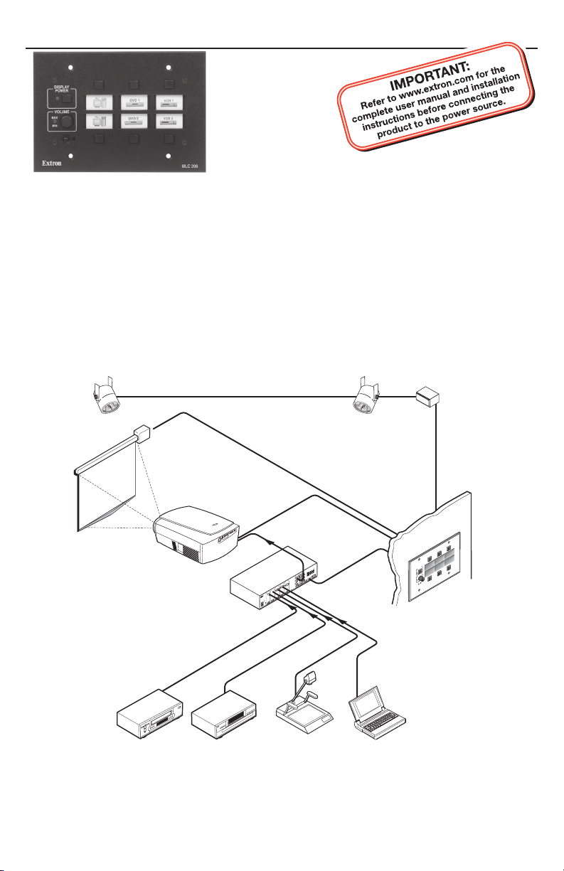
The Extron MediaLink™ Controller (MLC 206) provides infrared (IR) and RS‑232
remote control of a display device, contact closure control of items in a room, tally
outputs, and MediaLink Switcher control.
This guide provides instructions for an experienced installer to set up and operate
the MLC 206 MediaLink Controller.
When possible in the following pages, line drawings are used to clarify steps
discussed in the text.
Lighting
Control
Screen
Control
Projector
Control
VCR
1
T
U
P
IN
Y
-
R
O
E
D
I
V
R
L
z
H
0
/6
0
5
A
.2
0
V
40
-2
00
Extron
Switcher
1
DVD Laptop
5
T
U
P
IN
4
T
U
P
IN
3
T
U
P
IN
2
T
U
P
IN
R
B
L
Y
-
R
O
E
Y
D
I
V
R
L
Y
-
B
Y
R
L
R
L
Document
OUTPUT
V
0
7
m
h
o
8
m
h
o
4
O
E
MONO AMPLIFIED
M
D
I
M
V
O
C
V
U
Y
O
E
RS232
B
D
I
G
V
-
R
S
E
Y
R
LOSUR
E
CT C
A
T
D
/
ON
COMM LINK
C
H
C
Y
B
V
H
A
R
Y
R
UDIO OUT
A
L
V
C
G
Y
R
-
UX/MIX
B
A
L
N
R
U
T
E
EFFECTS
R
B
D
N
E
R
S
L
R
L
MLC 206 typical application diagram
Switcher
Control
p
to
p
a
L
D
DV
R
C
V
Y
A
L
P
R
IS
E
D
W
O
P
6
20
C
L
M
E
M
U
L
VO
/
X
A
M
N
I
M
Extron
Extron MLC 206
68-601-50
Rev. A
11 09
Page 2
MLC 206 Setup Guide, cont’d
MLC IR-IRCM wiring_01-05.eps
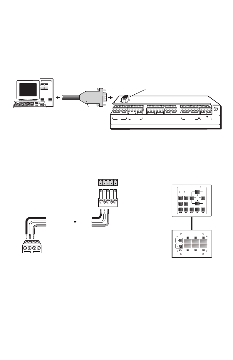
Step 1 — Computer Connection
The MLC 206 must be connected to a PC in order to configure the controller. The
configuration port, shown in the rear panel view below, is used for system control
and for loading configuration and driver files into the MLC.
1. Connect a host computer to the MLC 206 Config port via the rear
panel 9‑pin HD female RS‑232 connector. Use a serial cable with
9‑pin D connectors.
RS-232
Configuration Port
Config
Host Desktop
Computer
2. Connect all control modules that will be used in the system.
N
Control modules must be connected at this time so they can be configured
with the software. Connections for IR and serial control can be installed
after configuration.
9-pin
D Connector
A B C D E A B C
IR
Display/Source Control
D E A B C A BD
RS-232
1A 1B 2A 2B 3A 3B
Relays IR /RCM
1 2 3 4 5 6
Tally Out
Extron Switcher Control
33-644-01 A
07 01
MLS
/Power
A B C D
IR / RCM
A
+12 VDC
Ground ( )
B
Control signal (IRCM)
MLC 206
IR / RCM
port
A
B
CC
MLC 206 to a control module
A B C D E
Control
module
connector
IRCM control
module(s)
Total distance from
MLC: 150' (45.7 m) max.
DVD & VCR CONTROL
TITLE MENU
ENTER
PREV/REW
DVD VCR
TV/VCR
PLAY NEXT/FWD PAUSE STOP
Tx
TUNER
IRCM-DV+
DISPLAY
POWER
VCR DVD Laptop
VOLUME
MAX
MIN
Extron
MLC 206
MLC 206
2
Page 3
A B
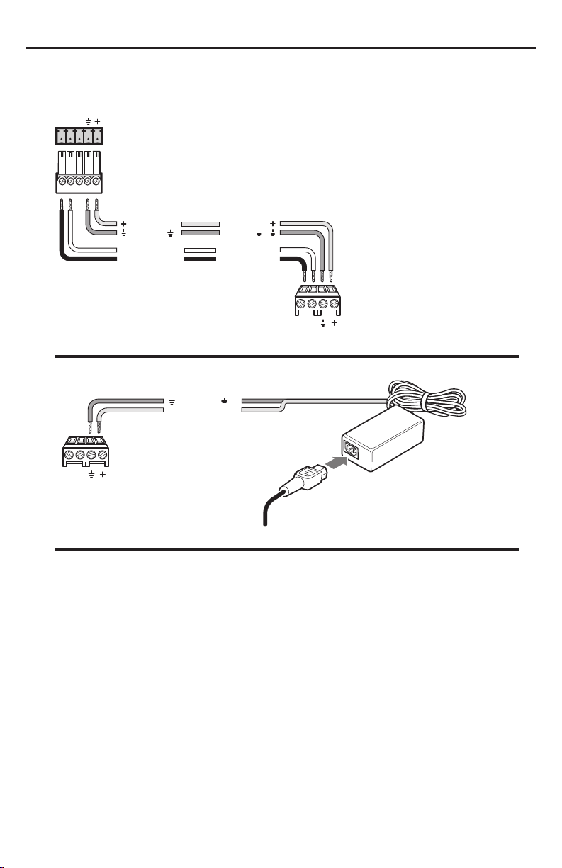
3. To power the MLC, connect a 12 VDC power supply or an optional
MediaLink Switcher (MLS) to the MLS/Power port, and connect the power
supply or the switcher to a power source.
MediaLink Switcher
MLC/RS-232
+12VDC
Ground ( )
B
Receive (Rx)
A
Transmit (Tx)
+12VDC
Ground ( )
Transmit (Tx)
Receive (Rx)
B
A
0 A ground wire must be connected
between the MLC and MLS.
A B
MLS / Power
MLC 206 powered by a MediaLink Switcher
Ground ( )
+12 VDC input
MLC
MLS/Power
A B
MLS / Power
port
Ground all devices
Connecting an MLC 206 to an external power supply
MLC 206
MLS/Power
port
An external
power supply
(12 VDC, 1 A max.)
Step 2 — Software Installation
The MLC must be configured before it can send commands to the projector or other
devices. Install the MediaLink Control Program software on the host PC. To install
the software, run SETUP.EXE from the Extron‑provided disk. Follow the instructions
that appear on the screen.
N
The software is also available at
www.extron.com.
3
Page 4

MLC 206 Setup Guide, cont’d
Step 3 — Setting up projector control
Device drivers allow the MLC 206 to control projectors and other source devices via
RS‑232 or IR.
N
To load a driver and configure the MLC 206:
1. Start the MediaLink Control Program.
The appearance of the screens varies depending on which
MLC 206 without accessories MLC 206 with an MLS switcher,
2. Load a projector driver: select the third tab, Controller (MLC) Config, and
It is strongly recommended that an RS-232 control (filenameRS1.mll) file for
controlling a projector be used whenever possible.
accessories (control modules and/or MediaLink Switcher)
are connected to the MLC, as shown in the following
pictures.
IRCM-DV+, and RCM-SC connected
select the Load Extron Driver button, as shown in the following illustration.
Choose the appropriate projector driver (filename.mll) from the on‑screen
menu. If the projector brand and model are not listed, check the Extron Web
site to see if a new driver is available or enter user‑defined RS‑232 strings. See
“Advanced Projector Config” in chapter 4 of the User’s Manual for details.
4
Page 5

3. Configure the buttons. Use the
drop‑down box associated with each
button to select the command to be
issued or function to perform, as
shown at right.
Each configured button has a green or red dot on it.
N
4. Choose a volume control option. Select Projector if
If a button has been previously configured, it will have a red (IR) or
green (RS-232) dot to indicate that an IR or RS-232 code has been associated
with it.
planning to use the projector display speakers or if using
the projector display as a preamp. Select Switcher (MLS)
when using an external switcher as an audio preamp or
amplifier.
Step 4 — IR learning
If there are no drivers available, the MLC can learn IR commands to control
projectors or other devices. IR learning is required to configure control modules to
control devices such as DVD players.
1. Select the third tab, Controller (MLC) Config.
2. Click on the appropriate button on the control module or the MLC to learn IR
codes.
N
If a button has been previously configured, it will have a red (IR) or
green (RS-232) dot to indicate that an IR or RS-232 code has been associated
with it.
5
Page 6

MLC 206 Setup Guide, cont’d
3. Click on the button labeled Learn IR to Button. A dialog box appears
indicating the button to which IR codes will be learned.
d
c
4. Click on OK to begin the learning process.
During IR learning hold the device remote control 4 inches to 14 inches
(10 cm to 36 cm) away from and directly in front of the MLC’s IR pickup
device.
DISPLAY
POWER
VCR DVD Laptop
VOLUME
MAX/
MIN
Extron
Aim the remote
control at the MLC’s
IR pickup devices,
press the remote’s
button, follow
on-screen prompts
4"–14"
(10–36 cm)
1 2 3
4 5 6
7 809
MLC 206
MLC 206
MediaLink Controller
Once the IR commands have been successfully
learned, the button will be shown with a red dot
(shown at right) and the button/function may be
named.
5. Repeat steps 2 through 4 to set up additional buttons.
6
OR
Page 7

MLC RS-232 display ctrl wiring_112202.eps
Step 5 — Completing the installation
1. Save the configuration by selecting Save CONFIGURATION as..., and name it
appropriately.
2. Connect the MLC 206 to the projector for RS‑232 projector control.
a. Disconnect the power from the MLC (and the optional MediaLink Switcher,
if applicable) and from the projector.
b. Plug the 9‑pin D connector of the RS‑232 projector control cable (such as an
Extron UC 50’ cable) into the projector RS‑232 port. A cable adapter may be
required.
c. Connect the other end of the projector control cable to the MLC
Display/Source Control RS‑232 port. Wiring depends on the projector. See
the diagrams below and on page 8, and the pin assignments in the projector
user manual. Also see the display driver setup document available from
the download page of the Extron Web site.
N
In most cases only the transmit (Tx), receive (Rx) and ground connections will
be needed. Wiring varies depending on the projector model.
Transmit (Tx)
A
Receive (Rx)
B
Request to send (RTS)
C
Clear to send (CTS)
D
Ground ( )
A B C D E A B C
IR
Display/Source Control
D E A B C A BD
RS-232
1A 1B 2A 2B 3A 3B
Relays IR/ RCM
E
To the RS-232 port of
the display/projector
1 2 3 4 5 6
Tally Out
Extron Switcher Control
MLS/Power
33-644-01 A
07 01
7
Page 8

MLC 206 Setup Guide, cont’d
MLC-IR emitter_wiring_QS_112202.eps
The UC cable pin assignments are shown in the following illustration.
To the
MLC 206
9
Black
8
Grey
Purple
7
6
Blue
5
Green
4
Yellow
Orange
Red
Brown
3
2
1
Pin #Color
Shield
UC Cable
Connector Shell
UC 50', 100' Cable Color Codes
3. Install the IR Emitter(s) in the IR port as shown in the following illustration,
and attach the head of each IR Emitter to an IR‑controlled device (VCR,
DVD player, projector).
N
Place the IR emitter directly over the IR pickup device of the equipment.
110 feet (33.5 m) maximum
Modulated IR
A
Ground
D
White striped wire only
0 Connect up to a maximum
To the
projector
1
5
Emitter
of 4 IR Emitters
6
9
IR
33-644-01 A
A B C D E A B C
IR
Display/Source Control
RS-232
1A 1B 2A 2B 3A 3B
D E A B C A BD
Relays IR/ RCM
1 2 3 4 5 6
Tally Out
Extron Switcher Control
MLS
07 01
/Power
4. Install any optional accessories (IR Link, relays, tally out) that will be connected
to the MLC 206. Refer to chapter two of the MLC 206 User’s Manual and to the
accessory manual(s) for wiring diagrams and installation details.
5. Reconnect the power supply or optional MediaLink Switcher (MLS) to the
MLS/Power port and connect power to all controlled devices.
6. Verify the system operates correctly when selections and adjustments are made
at the front panel and/or from the User Mode section of the control software.
Adjust cabling or retry IR learning as needed.
7. Disconnect the host PC from the MLC 206, remove power from the MLC
(unplug the power supply or switcher), and label the inputs (see the
MLC 206 User’s Manual for details).
8. Mount the MLC and accessories into the wall or furniture, and restore power.
8
Extron USA - West
Headqua rters
+800.6 33.9876
Inside USA / Canada Only
+1.714.491.1500
+1.714.491.1517 FAX
Extron USA - East
+800.6 33.9876
Inside USA / Canada Only
+1.919.863.1794
+1.919.863.1797 FA X
Extron Euro pe
+800.3 987.6673
Inside Europe Only
+31.33.4 53.4040
+31.33.4 53.4050 F AX
Extron Asia
+800.7 339.8766
Inside Asia Only
+65.63 83.440 0
+65.63 83.466 4 FAX
© 2009 Extron Electronics. All rights reserved.
Extron Japa n
+81.3.35 11.7655
+81.3.35 11.7656 FAX
Extron Chi na
+400. 883.1568
Inside China Only
+86.21. 3760.1568
+86.21. 3760.1566 FA X
Extron Mid dle East
+971.4.2 991800
+971.4.2 991880 FA X
 Loading...