

Page 1

MLC 104 MediaLink™ Controllers
Chapter Five
5
SIS™ Programming and Control
Host-to-MLC Communications
Command Tables
Page 2

PRELIMINARY
SIS™ Programming and Control
The MLC 104 Series controller can be remotely set up and controlled via a host
computer or other device (such as a control system) attached to the rear panel
Config/RS-232 port or LAN port, or the front panel Config port.
The MLC 104 or MLC 104 IP must be configured before use. As shipped the
controller can trigger basic input switching but cannot control any other devices
before being configured.
The MLC can be set up and controlled by using Extron’s Simple Instruction Set
(SIS) commands or the Extron Global Configurator software (version 2.0 or higher),
and both of those methods can be accessed via RS-232 or Ethernet LAN connection.
See chapter 2 for pin assignments and other details on the configuration and
control ports. For information on the software and the MLC’s embedded Web
pages, see chapter four.
MLC’s RS-232 protocol:
• 38400 baud
• 8 data bits
• 1 stop bit
• no parity
• no flow control
Both configuration ports require 38400 baud communication. This is a higher
speed than many other Extron products use. The Global Configurator (version
2.0 or higher) software or MLC 226/104 control software automatically sets
the connection for the appropriate speed. If using HyperTerminal or a similar
application, make sure the PC or control system connected to these ports is set
for 38400 baud.
LAN port defaults:
• MLC’s IP address: 192.168.254.254
• gateway’s IP address: 0.0.0.0
• subnet mask: 255.255.0.0
• DHCP: off
Host-to-MLC Communications
SIS commands consist of one or more characters per field. No special characters
are required to begin or end a command sequence. When the MLC determines that
a command is valid, it executes the command and sends a response to the host
device. All responses from the MLC to the host end with a carriage return and a
line feed (CR/LF = ), which signals the end of the response character string.
A string is one or more characters.
MLC-initiated messages
If you are communicating with the MLC via RS-232 or via a verbose Telnet
connection, when a local event such as a front panel selection or adjustment takes
place, the MLC responds by sending a message to the host. No response is
required from the host. The MLC-initiated messages are listed here (underlined).
(c)Copyright 2004, Extron Electronics, MLC 104 IP, Vx.xx
Day, DD Mon YYYY HH:MM:SS
Vx.xx is the firmware version number.
The MLC sends the boot and copyright messages under the following
circumstances:
• If the MLC is off and an RS-232 connection is already set up (the PC is cabled to
the MLC and a serial communication program such as HyperTerminal is open),
the connected MLC sends these messages via RS-232 when it is first powered on.
MLC 104 Series • SIS™ Programming and Control5-2
Page 3

• If the MLC is on, it sends the boot and copyright messages when you first open a
Telnet connection to the MLC. You can see the day of the week, date, and time if
the MLC is connected via Telnet, but not via RS-232. If you are using a Telnet
connection, the copyright message, date, and time are followed by a password
prompt.
X1
Chn
The MLC sends this response when an input is switched.
(where X1 is the input number)
Password information
The “ Password:” prompt requires a password (administrator level or user level)
followed by a carriage return. The prompt is repeated if the correct password is not
entered.
If the correct password is entered, the unit responds with “
Administrator
If passwords are the same for both administrator and user, the unit will default to
administrator privileges.
” or “ Login User ”, depending on password entered.
Error responses
When the MLC receives a valid SIS command, it executes the command and sends
a response to the host device. If the MLC is unable to execute the command
because the command is invalid or it contains invalid parameters, it returns an
error response to the host.
The error response codes and their descriptions are as follows:
E01 – Invalid input channel number (the number is too large)
E12 – Invalid port number
E13 – Invalid value (the number is out of range/too large)
E14 – Not valid for this configuration
E17 – System timed out
E22 – Busy
E24 – Privilege violation
E25 – Device is not present
E26 – Maximum number of connections has been exceeded
E27 – Invalid event number
E28 – Bad filename or file not found
Login
PRELIMINARY
Error response references
The following superscripted numbers are used within the command descriptions
on the following pages to identify commands that may respond as shown:
14
= Commands that give an E14 (not valid for this configuration) response if the
MLC’s current configuration doesn’t support that command
22
= Commands that yield an E22 (busy) response.
24
= Commands that give an E24 (privilege violation) response if you are not logged
in at the administrator level.
27
= Commands that may yield an E27 (invalid event number) response.
28
= Commands that may give an E28 (file not found) response.
Command Tables
Using the command/response tables
The MLC 104 IP can be controlled via either a Telnet (port 23) connection or a Web
browser (port 80) connection. All MLC 104 Series models can be controlled via
5-3MLC 104 Series • SIS™ Programming and Control
Page 4
SIS™ Programming and Control, cont’d
RS-232. The ASCII and URL commands listed in the tables starting on page 5-8
perform the same functions, but they are encoded differently to accommodate the
requirements of each port (Telnet or browser).
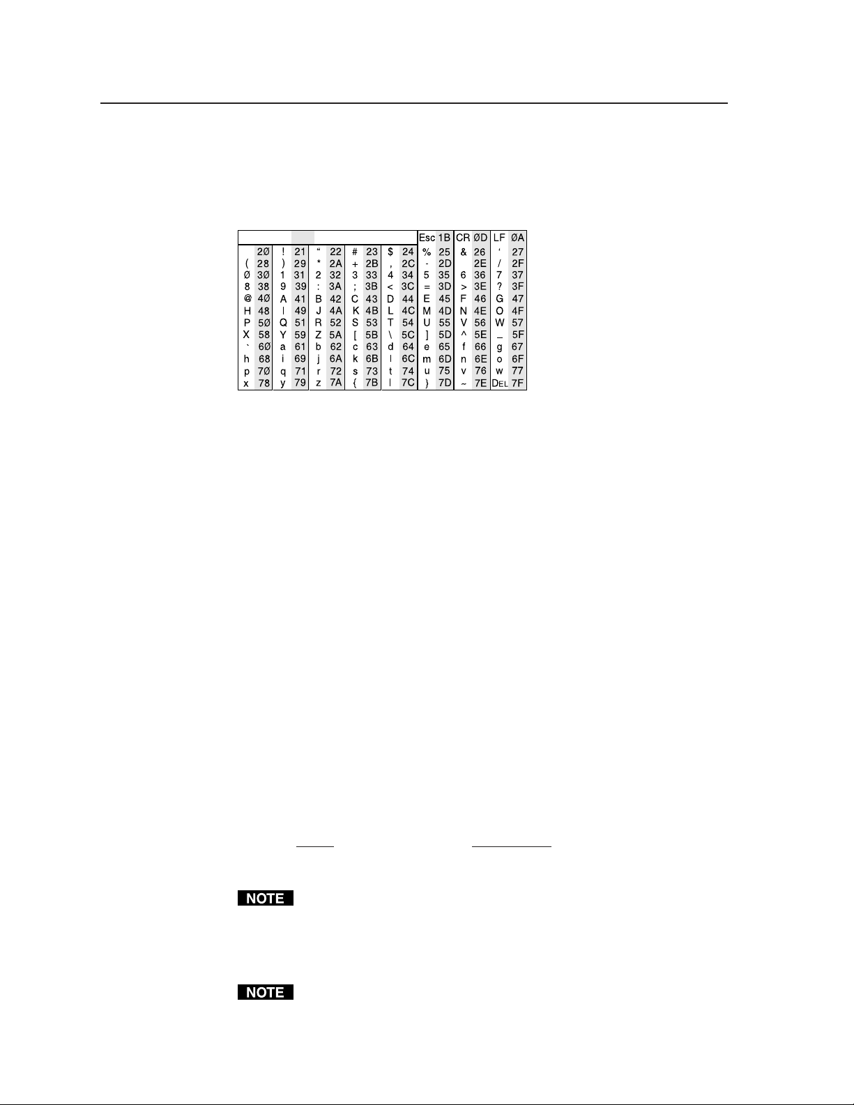
The following ASCII to hexadecimal (HEX) conversion table is for use with the
command/response tables.
ASCII to HEX Conversion Table
•
ASCII to Hex conversion table
The command/response tables list valid ASCII (for Telnet or RS-232) command
codes, the corresponding URL (uniform resource locator) encoded (for Web
browsers) command codes, the MLC’s responses to the host, and a description of
the command’s function or the results of executing the command.
PRELIMINARY
• Upper and lower case characters may be used interchangeably in the command
field unless otherwise specified.
• Commands may be sent back-to-back without spaces (for example, 2!65V1Z).
• Numbers can be entered as 1, 2, or 3 digits, e.g., 8V = 08V = 008V.
• There are a few differences in how to enter the commands depending on whether
you are using Telnet or a Web browser.
• When using these commands through a Web browser, the URL reference
is used to shorten the examples. “URL” refers to the full URL of the
control interface and Web page reference including all path information
(e.g., http://192.168.100.10/myform.htm).
• To send any of the commands using a Web browser you must prefix them
with the full URL followed by ?cmd=.
• For control via a Web browser, all non-alphanumeric characters must be
represented as the hexadecimal equivalent, %xx, where xx represents the
two-character hex byte. For example, a comma (,) would be represented
as %2C. Characters such as %, +, and the space character ( ) must be
encoded as hex bytes, or they will be misinterpreted by the MLC.
• Some characters differ depending on the method you use to send the
commands:
Telnet Web browser
Escape (hex 1B) W [must not be hex encoded]
Carriage return (hex 0D) Pipe character ( | ) [must not be hex encoded]
With Telnet you can use either an “Escape” command or a “W” command, and
the carriage return or the pipe character. With the Web browser, you are
required to use a “W” command and the pipe character.
In either method, {Data} = Data that will be directed to a specified port
and must be hex encoded if non-alphanumeric.
If you make adjustments (changes to volume, etc.), whether via the front panel
or via RS-232 or IP communication, it will take 1 minute 40 seconds (100
seconds) for the data in the MLC’s RAM to be saved to flash memory.
MLC 104 Series • SIS™ Programming and Control5-4
Page 5
X17
Symbol definitions
= CR/LF (carriage return/line feed) (hex 0D 0A)
= Carriage return (no line feed, hex 0D)
(use the pipe character, | , instead for Web
browser commands)
• = Space character
= Pipe (vertical bar) character
|
= Escape key (hex 1B)
Esc
X1
X2
X3
X5
X8
X11
X12
X13
X14
X15
(use W instead of Esc for Web browsers)
= Specific port number or relay number (01 – 99)
represented as two ASCII characters (two bytes)
Ports:
01 = rear host (Config/RS-232 port)
02 = front panel Config port
03 = slaved switcher (MLS port)
04 = projector port (Proj RS-232/IR)
= Command data section.
For Web encoding only: data will be directed to the
specified port and must be encoded (URL encoding)
if it is non-alphanumeric. Change any non-
alphanumeric character (%, +, |, , etc.) within
the data section into the corresponding hexadecimal
equivalent, %xx, where xx represents the twocharacter hex byte. For example, a space (hex: 20)
would be encoded as %20 (hex: 25 32 30) and a plus
sign (hex: 2B) would be encoded as %2B or hex 25
32 42.
= Greenwich Mean Time (GMT) offset value
(-12.00 to +14.00) represents the time difference
in hours and minutes (+/-hh:mm) relative to
Greenwich, England. The leading zero is
optional. For example, 5:30 = 05:30. Do not use
a plus (+) sign if the GMT offset is positive.
= On/off status
0 = off/disable
1 = on/enable
= Volume level (0 – 100 steps). When no MLS is
detected at the MLS port, the range is limited by
the max. volume command (X*47#).
Default volume = 40 when no MLS switcher is
detected at the MLS port.
Default volume = 100 when slave mode (X*41*)
is active and an MLS switcher is detected at the
MLS port.
= Version (typically listed to two decimal places,
e.g., x.xx)
= MLC’s name. The name is a text string of up to 24
characters drawn from the alphabet (A-Z),
digits (0-9), and minus sign/hyphen (-). No
blank or space characters are permitted as part
of a name. No distinction is made between
upper and lower case. The first character must
be a letter. The last character must not be a
minus sign/hyphen.
= Local date and time format
Set format (MM/DD/YY-HH:MM:SS).
Example: 01/18/05-10:54:00.
Read format (day of week, date month year
HH:MM:SS). Example: Tue, 18 Jan 2005
18:19:33.
= IP address (xxx.xxx.xxx.xxx). Leading zeros in each
of four fields are optional in setting values, and
they are suppressed in returned values.
MLC’s default: 192.168.254.254
= E-mail domain name; for example, extron.com
= Time in tens of milliseconds to wait until the first
response character is received via a serial port
before terminating the current receive
operation (Default = 10 = 100 ms, max. =
32767.) The response includes leading zeros.
For commands that use both
variables must be zero
or both must be non-zero.
In the RS (send data) command,
= Hardware (MAC) address (xx-xx-xx-xx-xx-xx)
X18
X17
and
is optional.
X20
X20
(00-05-A6-xx-xx-xx)
= Subnet mask (xxx.xxx.xxx.xxx). Leading zeros are
X19
optional in setting values in each of four fields,
and they are suppressed in returned values.
Default = 255.255.0.0.
= Time in tens of milliseconds to wait between
X20
characters being received via a serial port
before terminating the current command or
receive operation. The response includes
leading zeros.
(Default = 2 = 20 ms, max. = 32767)
For commands that use both
X17
and
X20
variables must be zero or both must be non-zero.
In the RS (send data) command,
= Parameter (#L or #D) to set either the Length of
X21
is optional.
X20
message to receive or the Delimiter value.
# = byte count (for L) or
# = a single ASCII character expressed in
decimal form (for D).
The parameter is case sensitive; you must use
capital D or capital L.
Byte count # can be from 0 to 32767,
default = 0.
The ASCII decimal # can be from 0 to 00255,
default = 00000L.
Examples:
A 3-byte length = 3L.
A delimiter of ASCII 0A = 10D.
The response from the MLC will include
leading zeros.
= Verbose/response mode status:
X22
0 = clear/none, default for Telnet connections;
responses are not echoed to the host
1 = verbose mode is on, default for RS-232
host control; responses are echoed to the host
and displayed to the user
2 = send tagged responses for queries
3 = verbose mode is on and tagged responses
are sent for queries
If tagged responses are enabled, all read commands
return the constant string + data, the same as for
setting a value. For example, for
the response is Ipn•
X12
CN ,
Esc
rather than just the
data.
= Priority status for receiving timeouts:
X23
0 = use send data string command parameters
(0 = default)
1 = use configure receive timeout command
parameters
= IP address converted from four octets to a single
X24
to a decimal number; e.g.:
10.13.0.254 = [(10*256*256*256) + (13*256*256)
+ (0*256) + (254)] =
[(10*2563) + (13*2562) + (0*2561) + (254*2560)] =
168,624,362 (decimal)
, both
, both
PRELIMINARY
5-5MLC 104 Series • SIS™ Programming and Control
Page 6
SIS™ Programming and Control, cont’d
X70
PRELIMINARY
= Baud rate: 300, 600, 1200, 1800, 2400, 3600, 4800,
X25
7200, 9600, 14400, 19200, 28800, 38400, 57600, or
115200
= Parity (only the first letter is needed):
X26
Odd
Even
None (default)
Mark
Space
= Data bits: 7, 8 (default = 8)
X27
= Stop bits: 1, 2 (default = 1)
X28
= Password (minimum length = 4 characters,
X33
maximum length = 12 characters,
no special characters are allowed)
A user password cannot be assigned if no
administrator password exists; the E14 error code
will be returned. If the administrator password is
cleared, then the user password and all extended
security level passwords are also removed.
= Daylight saving time (DST) is a region-specific 1-
X34
hour offset that begins in spring and ends in
fall. DST should be turned off in Hawaii,
American Samoa, Guam, Puerto Rico, the Virgin
Islands, the eastern time zone portion of the
state of Indiana, and the state of Arizona
(excluding the Navajo Nation).
0 = off/ignore
1 = USA on – starts on the first Sunday of April
at 2 am and ends at 2 am on the last Sunday of
October. For example, time in California is
GMT -8:00 from April to October and GMT -7:00
from November to March.
2 = Europe on – begins on the last Sunday in
March, ends on the last Sunday in October.
3 = Brazil on – beginning and ending dates vary
from year to year (October through March or
September through February). DST is not used
in equatorial areas.
= Event number, range = 0 - 99
X35
(valid only while events are running)
= I/O mode
X40
0 = input
8 = power sensor (triggered when an input
pulse starts/stops)
= Password to display on screen (response to
X41
password query). When the MLC connects to a
host device via RS-232, the password (
itself, is the response. When the connection is
via IP,
is 4 asterisks (****) if a password has
X41
been assigned, or it is an empty field ( ) if a
password hasn’t been assigned.
= E-mail event number or mailbox (1 - 64). The
X45
response will be two digits with a leading zero.
= E-mail recipient’s address (e.g., JDoe@extron.com)
X46
for the person to whom messages will be sent.
= Name (numeral) of e-mail file to be sent
X47
For CR (e-mail configuration) commands:
1.eml, 2.eml, ... 64.eml; and within the file the first
line contains the subject, the rest is the body of
the e-mail.
For SM (e-mail sending) commands: xxx,
where xxx = a number 1 to 999 corresponding to
the e-mail’s filename (xxx.eml). If xxx = 0 or no
parameter is given, the MLC sends the file that
was set via the CR command.
If file
.eml is not found when the SM command
X47
is executed, the MLC will send a default e-mail
message.
X33
= Default name: a combination of the modelname
X49
and the last 3 pairs of the MLC’s MAC address
(e.g., MLC-104-IP-00-02-3D)
= Extended-security (password) levels (1 to 10).
X51
The response will be two digits with a leading
zero.
= Connection’s security level
X52
0 = anonymous
1 – 10 = extended security levels 1 through 10
11 = user
12 = administrator
The response is two digits with a leading zero.
= IR playback file number (0 to 99) (no extension)
X57
The response includes leading zeros.
= IR playback function number (1 to 137). The
X58
response includes leading zeros. IR function
numbers 0 and 127 or higher can return
information only.
0 = return all data
129 = manufacturer
130 = model
131 = class
132 = remote
133 = creation date
134 = comments
137 = user file name (a descriptive name the
user/installer gave the file)
= IR playback mode
X59
0 = play once
1 = play continuously (send IR command
again with mode = 0 to stop mode 1 playback)
= IP connection timeout period in seconds. Each
X69
step is specified in 10-second intervals (1 65000, default = 30 = 300 seconds). If no data
is received during the specified period, the
Ethernet connection will be closed. Responses
are returned with leading zeros.
This variable is applicable only when the MLC
is connected via Ethernet. If the MLC is
connected via RS-232 protocol, only the global
timeout commands apply, and any commands
involving
= The number to insert into an email message if a
X70
return the E13 error response.
X69
____.eml file has an embedded server-side
include “<!--#echo var = “WCR|” -->” (the
command with no parameters.) The
Esc
),
numeral is a 16-bit number to be employed as
the user defines.
This is an optional parameter. Use 0 as a
placeholder if the optional
used but
= Specific input number (1 – 4)
X200
is not needed.
variable is
X47
1 = input 1
2 = input 2
3 = input 3
4 = input 4
= Lamp hours elapsed (as a five-digit number, max.
X205
= 99999 hours) The response includes leading
zeros. The default (99999 hours) is the
response to SIS commands (via Telnet or RS-
232) if elapsed lamp hours have not been set.
In the MLC’s internal Web pages, “N/A” is
displayed if lamp hours have not been set.
= Voltage
X206
= Temperature in degrees Celsius (the response is
X207
3 digits including leading zeros)
MLC 104 Series • SIS™ Programming and Control5-6
Page 7

= Display (projector on/off) status as tracked by the
X208
X209
X210
X211
X212
X213
X214
X215
X216
display driver
0 = display power is off
1 = display power is on
2 = display is powering down/off (cooling
down)
3 = display is powering up/on (warming up)
= Front panel lockout (executive mode ) status
0 = off/unlocked (default)
3 = on, disable/lock entire front panel (buttons,
volume control) and optional connected SCP
= IR/serial port configuration
0 = IR ports (0 V – 5 V) (default)
1 = RS-232 ports (±5 V)
= Status (in hexadecimal characters) of script or
firmware button control. This variable is an 8-
digit hexadecimal character calculated from a
binary bit map. See page 5-27 for details.
= Status (in hexadecimal characters) of control of
lamp enabling (control of all button lights).
This variable is an 8-digit hexadecimal character
calculated from a binary bit map. See page 5-29
for details.
= Power sensor status:
00 = power sensor is connected and is not
sensing projector power (detector voltage is low,
signal pin voltage is high)
01 = power sensor is connected and is sensing
projector power (detector voltage is high)
02 = power sensor is disconnected or sensor is
connected but the sensitivity is set too high
(voltage is low at both the detector and signal
pin)
= Power sensor signal pin status
00 = voltage is low
01 = voltage is high
Leading zeros will be used in responses to
commands that use this variable.
= IR/Serial Output port number
1 = projector port
= Display mute or connection status
0 = off/disconnected
1 = on/connected
2 = unknown/unavailable
PRELIMINARY
5-7MLC 104 Series • SIS™ Programming and Control
Page 8
SIS™ Programming and Control, cont’d
X200
X200
X208
X208
X208
= 1, 2, 3, 4)
X200
(
, 0 = display power is off
X208
= The MLC responds with an E14 error
code (invalid for this configuration) if the
desired input isn’t part of the switching
14
(audio and video).
= The MLC sends a “busy” response (E22)
rotation (is not set up to switch inputs).
Events are still triggered, though.
if switching functions are locked.
22
The display is powering off.
provides a way to set the power status to
match the actual state of the projector.
For
1 = display power is on
2 = display is powering down/off
= 0 (off), 1 (on), or 2 (unknown)
X216
provides a way to set the status to match the
3 = display is powering on (warming up).
actual state of the projector.
PRELIMINARY
Select input
%21 Chn
X200
!
X200
(host to switcher) (host to switcher) (switcher to host)
On (discrete).
Off (discrete).
This command is used only by scripts. It
Show the display power status.
X208
%2A0P Pwr
X208
*0P
X208
Mute.
Unmute.
This command is used only by scripts. It
X216
X216
X216
Show display mute status.
X216
%2A0M Mut
X216
*0M
X216
14, 22
Command/response table for SIS commands
Command ASCII (Telnet) URL Encoded (Web) Response Additional description
Select an input
Input selection
Turn display power on 1P 1P Pwr
Turn display power off 0P 0P Pwr
Display (projector) power
MLC 104 Series • SIS™ Programming and Control5-8
Example:PP 2
View display power status P P
Set power status
Turn display mute on 1M 1M Mut
View display mute status M M
Set mute status
Turn display mute off 0M 0M Mut
Display mute
Page 9
X8
= The MLC responds with an E14 error
X8
X8
14
= volume level (0 to 100). Default = 40 if
X8
code (invalid) if the MLC is in volume
increment/decrement mode (vol. mode 1).
no switcher is connected, 100 if an MLS
switcher is connected. The maximum level
is limited by the X*47# command.
Example: set volume to 27.
Increase audio output.
Show the output volume.
Decrease audio output.
Show the output volume.
as selecting input 0.
Unmute all audio outputs.
= 0 (off) or 1 (on).
X5
can be made from the front panel in
addition to via RS-232, Telnet, or Web
= The MLC responds with an E24 error
(privilege violation) if the connected user is
not logged in at administrator security level.
browser.
24
Specify the volume for audio output.
V Vol
X8
V
X8
(host to switcher) (host to switcher) (switcher to host)
14
Decrease audio output.
X8
Show the status of audio mute.
X5
PRELIMINARY
0X 0X Exe 0 Default setting. Adjustments & selections
24
Command/response table for SIS commands (continued)
Command ASCII (Telnet) URL Encoded (Web) Response Additional description
Set the overall output volume
Volume adjustment (discrete, for volume mode = 0)
Example: 27V 27V Vol027
Increment the volume +V %2BV Vol
Decrement the volume -V %2DV Vol
View the volume level V V
Increment the volume +V %2BV Vol+ Increase audio output.
Decrement the volume -V %2DV Vol-
Volume adjustment (increment/decrement, for volume mode = 1)
View the volume level V V ---
Mute on 1Z 1Z Amt1 Mute all audio outputs. This is not the same
Mute off 0Z 0Z Amt0
Audio mute
View the audio mute status Z Z
Disable lockout modes
Front panel security lockout modes (executive modes)
5-9MLC 104 Series • SIS™ Programming and Control
Page 10
SIS™ Programming and Control, cont’d
X205
X205
X205
) used by scripts.
X216
PRELIMINARY
adjustments via MLC and SCP. Make
selections, changes, and configure features
via RS-232 or Ethernet only. All front panels
in the control system are locked.
= 0 (off, unlocked) or 3 (front panels
X209
locked/disabled)
Executive mode is off.
represents the number of elapsed hours
X205
of projector lamp use. The MLC responds
with 2 sets of lamp hours. The number of
Show lockout (executive mode) status.
X209
*
X205
represents the five-digit numeric value
elapsed hours are shown if a lamp’s status is
X205
set. If a lamp’s status has not been set, it is
shown as the default (99999 hours).
for elapsed lamp use hours, and it is used by
script to determine the number sent in
X205
*
= The MLC responds with an E24 error
(privilege violation) if the connected user is
response to the “view lamp hours”
command (6S).
not logged in at administrator security level.
24
X205
*
This command lets you know whether the
X216
%2A 6S Lhr *
X205
%2A 6S Lhr *
X205
%2A
X205
= 0 (disconnected), 1 (connected), or
X216
MLC’s scripts have determined if the
display is still connected to the MLC.
connection status flag (
2 (unknown)
0 = projector not connected.
1 = projector is connected.
2 = undetermined status.
This command is used to reset the projector
X216
%2A 7S Pcs
X216
*6S
3X 3X Exe 3 Lock all front panel selections and
(host to switcher) (host to switcher) (switcher to host)
24
X205
24
Example:X 0
Command/response table for SIS commands (continued)
Enable lockout mode 3
Command ASCII (Telnet) URL Encoded (Web) Response Additional description
View the lockout mode status X X
View lamp hours status 6S 6S
Status commands
Set lamp hours status for 1 lamp
MLC 104 Series • SIS™ Programming and Control5-10
*6S
X205
*
X205
24
View connection status 7S 7S
Set lamp hours status for 2 lamps
*7S
X216
24
Set projector connection status
Page 11
is as follows:
X207
X213
= voltage.
X206
= temperature in degrees Celsius (the
Power Sensor that monitors the projector/
display, this tells you whether the display is
still powered on.
00 = power sensor is connected and is not
sensing projector power (detector voltage is
low, signal pin voltage is high).
01 = power sensor is connected and sensing
projector power (detector voltage is high).
02 = sensor is disconnected or sensor is
connected but sensitivity is too high (voltage
is low at both the detector and signal pin).
If the switcher is connected to an Extron
X213
Power sensor signal pin status:
X214
00 = voltage is low.
01 = voltage is high.
View all voltages and the MLC’s internal
temperature at once.
X206
power input.
Display the operating voltage of the MLC’s
Serial and projector ports.
Display the operating voltage for the IR/
X206
X206
response is 3 digits including leading zeros).
Display the internal operating temperature.
X207
PRELIMINARY
(host to switcher) (host to switcher) (switcher to host)
Command/response table for SIS commands (continued)
View power sensor status 8S 8S
Command ASCII (Telnet) URL Encoded (Web) Response Additional description
View power sensor signal pin status 9S 9S
View all voltage & temp. status 11S 11S responses from commands 12S•14S•16S•20S
View +12 V power supply voltage 12S 12S +
View -10 V IR/Serial bus voltage 16S 16S -
View +3.3 V IP Link/FPGA voltage 14S 14S +
View internal temperature status 20S 20S
5-11MLC 104 Series • SIS™ Programming and Control
Page 12

SIS™ Programming and Control, cont’d
must both a) be missing, b) equal zero, or c) be nonzero.
X20
and
X17
PRELIMINARY
X2
|
RS
X21
%2A
X20
%2A
X17
%2A
X2
X1
W
RS
X21
*
X20
*
X17
*
X1
(host to switcher) (host to switcher) (switcher to host)
Esc
response from command
response from command
<data>
|
, convert nonalphanumeric characters to hex numbers. A space (hex = 20) is encoded as %20. A plus sign (hex = 2B) is
X2
W04%2A4%2A7%2A3L RS
are not specified, the default values are used. For this command,
X20
and
X17
04*4*7*3L RS <data>
Esc
Example:
is optional. If
X21
*
X20
*
= specific port number (01 – 99)
X17
X1
*
01 = rear host (Config/RS-232 port)
02 = front panel Config port
= command data section. For Web encoding for
X2
03 = slaved switcher (MLS port)
04 = projector port (Proj RS-232/IR)
encoded as %2B.
= time in tens of ms for the MLC to wait until receipt of the first response character before terminating the current receive operation (default = 10 = 100 ms, max. = 32767).
= time in tens of ms for the MLC to wait between characters being received via a serial port before terminating the current receive operation
X17
X20
The response includes leading zeros.
(default = 2 = 20 ms, max. = 32767). The response includes leading zeros.
= #L or #D. The letter parameter is case sensitive (requires a capital “D” or capital “L”). The response includes leading zeros.
X21
Length of the message to be received.
L =
Examples: A 3-byte length = 3L. A delimiter of ASCII 0A = 10D.
Delimiter value.
# = byte count (for L) or a single ASCII character expressed in decimal form (for D).
Byte count # can be from 0 to 32767, default = 0. The ASCII decimal delimiter # value can be from 0 to 00255, default = the byte count.
D =
These commands apply to any port that uses RS-232 communication: both 1-way (output) and 2-way (bidirectional) RS-232 communication.
Command/response table for SIS commands (continued)
Command ASCII (Telnet) URL Encoded (Web) Response Additional description
Send data string
Serial data port configuration and use
MLC 104 Series • SIS™ Programming and Control5-12
Page 13

X1
X25
.
X28
X1
X17
X1
), data bits
X26
) for port
X28
), parity (
X25
), and stop bits (
= 300, 600, 1200, 1800, 2400, 3600, 4800,
X27
(
= parity (only the first letter is needed):
X25
X26
Odd
Even
None (default)
Mark
7200, 9600, 14400, 19200, 28800, 38400, 57600,
or 115200 baud.
Space.
= waiting time in
X17
= data bits: 7, 8 (default = 8).
= stop bits: 1, 2 (default = 1).
X27
X28
no parity, 8 data bits, and 1 stop bit.
= #L or #D (see
X21
.
X1
: 0 = default, use send
X23
= waiting time in tens of ms
X20
between characters before terminating) and
character before terminating the receive
operation,
priority status (
data string command parameters; 1 = use
configure receive timeout command
parameters) for port
tens of ms until receipt of the first response
previous page). The response includes
leading zeros.
Set baud rate (
X28
,
X27
,
X26
,
|
•Ccp
CP
X28
Cpn
%2C
X27
%2C
X26
%2C
X25
%2A
X1
CP
W
X28
,
X27
,
X26
,
X25
*
X1
Esc
(host to switcher) (host to switcher) (switcher to host)
24
Set the time to wait (
X21
,
X23
,
X20
|
CE
X21
,
•Cce
Cpn
,
X27
,
X26
|
,
X25
Cpn4•Ccp9600,N,8,1 Set the projector control port for 9600 baud,
%2A
X23
%2A
X20
%2A
X17
|
CP
%2A
X1
X1
CE
W
X21
*
X23
*
X20
*
X17
CP W
*
X1
4*9600,N,8,1CP W4%2A9600%2CN%2C8%2C1CP
Esc
Esc
X1
Esc
X21
,
X23
,
X20
,
X17
|
CE
X1
CE W
X1
Esc
PRELIMINARY
24
Example:
Command/response table for SIS commands (continued)
Configure serial port parameters
Command ASCII (Telnet) URL Encoded (Web) Response Additional description
Configure receive timeout
View serial port parameters
View receive timeout
5-13MLC 104 Series • SIS™ Programming and Control
Page 14

SIS™ Programming and Control, cont’d
X215
X215
= IR
X58
= IR playback
X59
(1 = projector port).
X215
= the IR file number (0-99),
X57
port number
mode (0 = play once, 1 = play continuously).
function number (1-137),
description (e.g., Power On, Power Off,
) = 0. Also, the response includes leading zeros.
X59
Send an IR command via IR/Serial Output
X59
,
X58
,
X57
,
|
IR
X59
Irs
{descriptive text} The response to this command is the name/
= the IR file number (0-99), as in files
X57
Enter, Play, Stop, RGB, Menu) of the specific
command you ask about.
1.eir, 2.eir, 3.eir, etc. stored in the controller.
= IR function number (1-137), which
X58
Each ___.eir file contains commands for a
specific device.
= 0, the MLC will return all data. See
X58
corresponds to a specific function/
command set contained within the file. If
=
X59
.
X58
(1 = projector port) for either
X215
Power command.
defined or does not exist, so the controller
page 5-6 for additional details on
IR playback mode.
returns E13, the invalid value error number.
number
This command sets IR/Serial Output port
X210
*
POWER Command/function 1 in file 3.eir is the
E13 Command/function 2 in file 3.eir is not
Irc
= 1) output.
X210
= 0) or RS-232 (
includes a placeholder zero in the
X210
X210
response.
IR (
which is RS-232 in this example.
X210
01 View the projector port’s configuration,
PRELIMINARY
%2C
X58
%2C
X57
%2C
X215
IR
W
X59
,
X58
,
X57
,
X215
(host to switcher) (host to switcher) (switcher to host)
Esc
28
|
IR
X58
%2C
X57
W
IR
X58
,
X57
Esc
28
To stop mode 1 IR command playback (continuous playback), send the IR command again but with playback mode (
Command/response table for SIS commands (continued)
Command ASCII (Telnet) URL Encoded (Web) Response Additional description
Send an IR command
IR/serial data port
Get IR command info
|
|
3,1IR W3%2C1IR
3,2IR W3%2C2IR
Esc
Esc
Example:
Example:
|
IC
X210
%2A
X215
|
IC
X215
|
IC W
X210
24
*
X215
Esc
IC W
X215
Esc
1 IC W1 IC
Esc
An IR driver must be loaded into the MLC before IR command information can be read.
Example:
Configure an IR/Serial Out port
View an IR/Serial port’s config.
MLC 104 Series • SIS™ Programming and Control5-14
Page 15

=
X69
timeout period for all Telnet sessions.
IP connection timeout period in seconds.
Each step is specified in 10-second intervals
(1 - 65000, default = 30 = 300 seconds). If no
data is received during the specified period,
the Ethernet connection will be closed.
Responses are returned with leading zeros.
This variable is applicable only when the
MLC is connected via Ethernet, and you
must be logged in as an administrator to
change this setting.
return the E13
X69
= timeout period in seconds. See the
X69
the currently open Telnet session only.
When you start another Telnet session, it
uses the default global port timeout period.
description above.
This variable is applicable only when the
MLC is connected via Ethernet. If the MLC
is connected via RS-232 protocol, only the
global timeout commands apply, and any
commands involving
error response.
The global port timeout is the default
X69
Pti 1*
|
TC
X69
TC W1%2A
X69
1*
Esc
(host to switcher) (host to switcher) (switcher to host)
24
The current port timeout period applies to
X69
X69
Pti 0*
|
TC
X69
|
TC W0%2A
X69
1TC W1TC
0*
Esc
Esc
24
X69
PRELIMINARY
|
0TC W0TC
Esc
Set global IP port timeout period
Command/response table for SIS commands (continued)
Ethernet data port configuration and use
Command ASCII (Telnet) URL Encoded (Web) Response Additional description
Set current port’s timeout period
View global IP port timeout period
View current port’s timeout period
5-15MLC 104 Series • SIS™ Programming and Control
Page 16

SIS™ Programming and Control, cont’d
=
X40
).
X40
= digital input state:
X43
Set the input/output mode (
0 = input (default)
8 = power sensor
When set for power sensor, the input state is
triggered when the input pulse starts or
stops at the power sense port.
X40
0 = off
X40
)
X11
1 = on
to two decimal places. This query yields the
number of the currently running version of
the user-updatable firmware.
Show the MLC’s firmware version (
X11
{response from 2Q}–{response from 3Q}–{response from 4Q}
Show the bootstrap, factory-installed, and
updated firmware versions. See 2Q, 3Q, and
4Q below.
-Thu, 15 Sep 2005 22:42:14 GMT)
replaceable, but you may need this
information during troubleshooting.
The bootstrap firmware is not user-
X11
Factory-installed firmware is different from
the bootstrap firmware, but it is also not user-
replaceable. This firmware was installed at
the factory; it is the version the controller
(kernel version–model description–date time of upload)
X11
reverts to after a mode 1 reset (see chpt. 2).
In this example the factory firmware version
is 1.00 and the IP Link kernel version is 1.18
for the MLC 104, dated 20 January 2005.
PRELIMINARY
%5B Iom 2*
X40
[2%2A
X40
(host to switcher) (host to switcher) (switcher to host)
2*
24
An input voltage below 1.2 VDC is considered to be logic low. An input voltage above 1.2 VDC is considered to be logic high. These thresholds are not adjustable.
Example: 1Q 1Q 1.01
Command/response table for SIS commands (continued)
Command ASCII (Telnet) URL Encoded (Web) Response Additional description
Set the input (I) mode
Digital input data port (power sense port)
View the digital input mode 2[ 2%5B
View the digital input state 2] 2%5D
Query firmware version number Q or 1Q Q or 1Q
Firmware version, part number & information requests
Query verbose version information 0Q 0Q
Example: 0Q 0Q 1.03-1.00(1.18-MLC104 -Thu, 20 Jan 2005 09:41:47 GMT)-1.00*(1.18-MLC104
Query bootstrap firmware version 2Q 2Q
Example: 2Q 2Q 1.03
Example: 3Q 3Q 1.00(1.18-MLC104 -Thu, 20 Jan 2005 09:41:47 GMT)
Query factory firmware version 3Q 3Q
MLC 104 Series • SIS™ Programming and Control5-16
Page 17

Use this command to find out which version
X200
of the firmware, if any was uploaded into
the controller after it left the factory.
In this example the current firmware version
is 1.00, the IP Link kernel version is 1.18, for
the MLC 104, dated 15 September, 2005.
(FPGA) firmware version to two decimal
places (x.xx).
is the input number.
Show the MLC’s part #. 60-573-00 =
X200
MLC 104 IP, 60-665-00 = MLC 104.
Show which input is active (selected).
or MLC 104
available memory for system operations.
Show amount of user memory used and
total available user memory.
14 = MLS 406 SA
08 = MLS 103 SV
09 = MLS 102 VGA
10 = MLA-VC10
11 = MLS 304 MA
Show the absence of or types of connected
devices.
For :
00 = not present
01 = MLS 306
02 = MLS 506
03 = MLS 506 MA 70 V
12 = MLS 406
13 = MLS 406 MA
04 = MLS 506 SA
05 = MLS 506 MA 100 V
15 = MLS 304 SA
06 = MLS 100 A
07 = MLS 103 V
(kernel version–model description–date time of upload)
X11
(host to switcher) (host to switcher) (switcher to host)
Show the field-programmable gate array
X11
For ##:
00 = not present
Prefixes for connected devices:
P1 = SCP #1, address 0
the MLC 104 Series because they do not support
control modules (IRCMs, ACMs, CCs, RCMs)
* 00 is the value (##) for K1, K2, K3, and K4 for
a slaved MLS switcher.
P2 = SCP #2, address 1
K1 = control module #1, address 0*
K2 = control module #2, address 1*
K3 = control module #3, address 2*
K4 = control module #4, address 3*
S = MediaLink device, typically
PRELIMINARY
In a query response, an asterisk (*) after the version number indicates the version that is currently used.
A question mark (? or ?.??) indicates that the factory default firmware is the only firmware loaded in the switcher.
A carat (^) indicates the version of firmware that should be running, but, since a mode 1 reset was performed, the factory default firmware version is loaded and running instead.
An exclamation point (!) indicates that the firmware is corrupted.
Example: 4Q 4Q 1.00*(1.18-MLC104 -Thu, 15 Sep 2005 22:42:14 GMT)
Command/response table for SIS commands (continued)
Query updated firmware version 4Q 4Q
Command ASCII (Telnet) URL Encoded (Web) Response Additional description
Query FPGA version 32Q 32Q
Request the MLC’s part number N N 60-xxx-00
Request A/V input number I I Chn
Example: 4I 4I 217856 Bytes Used out of 7232 KBytes
Request the model description 2I 2I MLC 104 w/ IP MLC 104 with IP control.
Request the model name 1I 1I MLC 104 IP
Request system memory usage 3I 3I # bytes used out of # of kbytes Show amount of memory used and total
Request user memory usage 4I 4I # bytes used out of # of kbytes
Request status of attached hardware 32I 32I P1##•P2##•K1##•K2##•K3##•K4##•S
5-17MLC 104 Series • SIS™ Programming and Control
Page 18

SIS™ Programming and Control, cont’d
), such as “AuditoriumMLC”,
X12
PRELIMINARY
This example includes one SCP (P101) and
no slaved switcher.
This example includes one SCP (P201) and
an MLS 102 VGA (S09).
= the name the MLC was shipped with:
choosing (
“Rm316-AVcenter”, or “exec-boardroom-
ctrl”. The name consists of up to 24
alphanumeric characters (and the minus
sign). The first character must be a letter,
Change the MLC’s name to one of your
X12
Ipn•
|
X49
MLC-104-IP-##-##-## or MLC-104-##-##-##,
a combination of the model name and the
last 3 pairs of hex numbers in the
the last character cannot be a minus sign
(hyphen). Case does not matter.
controller’s MAC address (e.g., MLC-104-IP-
X49
Ipn•
|
CN
X12
is the MLC’s factory default name.
is the MLC’s current, user-defined unit
X12
00-02-3D).
= Local date and time format.
X49
X13
name.
The set format is MM/DD/YY-HH:MM:SS.
X49
or
X12
X13
Ipt•
|
|
CT
X13
= Local date and time format.
X13
Example: 03/08/05-10:54:00.
The Read format is day of week, DD month
year HH:MM:SS.
Example: Tue, 08 Mar 2005 18:19:33.
X13
|
CN W
X12
(host to switcher) (host to switcher) (switcher to host)
32I 32I P100 P201 K100 K200 K300 K400 S09
Esc
24
•CN W%20CN
Esc
24
Examples: 32I 32I P101 P200 K100 K200 K300 K400 S00
Command/response table for SIS commands (continued)
Command ASCII (Telnet) URL Encoded (Web) Response Additional description
Set the unit name
IP setup commands
Set unit name to factory default
MLC 104 Series • SIS™ Programming and Control5-18
CT W
CN WCN
Esc
Read the unit name
X13
Esc
24
Set time/date
CT WCT
Esc
Read time/date
Page 19

X3
) for the MLC’s location. GMT
X3
= Daylight saving time (DST) is a
value (
offset (-12.00 to +14.00) represents the time
difference in hours and minutes (+/-hh:mm)
relative to Greenwich, England. The leading
zero is optional. For example, 5:30 = 05:30.
Do not use a plus (+) sign if the GMT offset
X34
is positive.
region-specific 1-hour offset that begins in
spring and ends in fall. DST should be
turned off in Hawaii, American Samoa, most
equatorial regions, Guam, Puerto Rico, the
Virgin Islands, the eastern time zone portion
of the state of Indiana, and the state of
Arizona (excluding the Navajo Nation).
0 = off/ignore
1 = USA on – starts on the first Sunday of
April at 2 am and ends on the last Sunday of
October. For example, time in California is
GMT -8:00 from April to October and GMT -
7:00 from November to March.
2 = Europe on – begins on the last Sunday in
March, ends on the last Sunday in October.
3 = Brazil on – beginning and ending dates
vary from year to year. DST is not used in
equatorial areas.
= IP address (xxx.xxx.xxx.xxx). Leading
= 0 (off) or 1 (on).
X14
X5
zeros in each of the four fields are optional
in setting values.
= hardware (MAC) address (xx-xx-xx-
X18
suppressed in returned values.
xx-xx-xx).
Set the Greenwich Mean Time (GMT) offset
Ipz
|
CZ
X3
CZ W
X3
Esc
(host to switcher) (host to switcher) (switcher to host)
X34
X3
Ipx
|
CX
|
X34
CX W
X34
CZ WCZ
Esc
Esc
24
X34
|
CX WCX
Esc
X5
Idh 1
Idh 0
|
|
|
1 DH W1DH
0 DH W0DH
DH WDH
Esc
Esc
Esc
X14
Ipi•
X14
|
CI
X14
|
CI W
X14
Esc
Esc
Leading zeros in each of the four fields are
X18
|
PRELIMINARY
CI WCI
CH WCH
Esc
24
Command/response table for SIS commands (continued)
Set GMT offset
Command ASCII (Telnet) URL Encoded (Web) Response Additional description
Set daylight saving time
Read GMT offset
24
Set DHCP on
Read daylight saving time
24
24
Set DHCP off
View DHCP mode
Set IP address
Read hardware address (MAC)
Read IP address
5-19MLC 104 Series • SIS™ Programming and Control
Page 20

SIS™ Programming and Control, cont’d
X12
:
X22
CN , the response is Ipn•
Esc
= subnet mask (xxx.xxx.xxx.xxx).
X19
Syntax is the same as for IP addresses.
= IP address (xxx.xxx.xxx.xxx). Leading
X14
Leading zeros are optional in setting values.
Enable or disable the verbose mode via this
zeros are optional
command. For
0 = clear/none, default for Telnet connections;
responses are not echoed to the host
1 = verbose mode is on, default for RS-232
host control; responses are echoed to the
host and displayed to the user
2 = send tagged responses for queries
3 = verbose mode is on and tagged
responses are sent for queries.
:
X52
For
00 = anonymous
01 – 10 = extended security levels 1 through
10
11 = user
12 = administrator
The response is two digits with a leading 0.
PRELIMINARY
X19
Ips•
Leading zeros are suppressed.
X19
|
CS
X19
|
CS W
X19
Esc
(host to switcher) (host to switcher) (switcher to host)
CS WCS
Esc
X14
X14
Ipg•
|
CG
|
X14
CG W
X14
CG WCG
Esc
Esc
24
X22
Vrb
|
CV
X22
CV W
X22
Esc
24
X22
[total number of client connections]
002 Example: This shows two client connections.
|
|
|
CV WCV
CC WCC
CC WCC
Esc
Esc
Esc
X52
|
CK WCK
Esc
24
Command/response table for SIS commands (continued)
Set subnet mask
Command ASCII (Telnet) URL Encoded (Web) Response Additional description
Set gateway IP address
Read subnet mask
Set verbose response mode on/off
Read gateway IP address
If tagged responses are enabled, all read commands return the constant string + data, the same as for setting a value. For example, for
rather than just the data.
MLC 104 Series • SIS™ Programming and Control5-20
The controller can send out unsolicited information (such as notice of a volume or input change or a change in some other setting). That is called a verbose (wordy) relationship
between the controller and a connected device. For a direct RS-232 connection, the controller is set for verbose mode by default. When connected via Ethernet, verbose mode is
disabled (by default) in order to reduce the amount of communication traffic on the network. If you want to use the verbose mode with a controller connected via Ethernet, this
mode must be set to “on” each time you reconnect to the controller.
Example:
Get a connection listing
Read verbose mode status
Read connection’s security level
Password and security settings
Page 21

,
X33
X41
), itself, is the
X33
= Password to display on
X41
is 4 asterisks (****) if a password has been
assigned, or it is an empty field ( ) if a
screen (response to password query). When
the MLC connects to a host device via RS-
232, the password (
4 to 12 alphanumeric characters). The
password is case sensitive. Special
characters (spaces, symbols) are not
allowed.
response. When the connection is via IP,
password hasn’t been assigned.
Set the administrator access password (
X41
Ipa•
Ipa• Clear/remove all passwords (administrator
and user).
X41
= Password
X41
is 4 to 12
X33
Set the user password (
alphanumeric characters). The password is
case sensitive. Special characters (spaces,
symbols) are not allowed.
to display on screen.
X41
Ipu•
X41
Ipu• This clears the user password only.
|
CA
X33
CA W
X33
Esc
(host to switcher) (host to switcher) (switcher to host)
24
|
|
|
CU
X33
CU W
•CA W%20CA
Esc
24
X33
CA WCA
Esc
Esc
14, 24
A user password cannot be assigned if an administrator password does not exist. Also, if the administrator password is cleared, the user password is also cleared.
Command/response table for SIS commands (continued)
Set administrator password
Command ASCII (Telnet) URL Encoded (Web) Response Additional description
Clear administrator password
Set user password
Read administrator password
|
|
•CU W%20CU
CU WCU
Esc
Esc
24
A user password cannot be assigned if an administrator password does not exist. Also, if the administrator password is cleared, the user password is also cleared.
Clear user password
Read user password
PRELIMINARY
5-21MLC 104 Series • SIS™ Programming and Control
Page 22

SIS™ Programming and Control, cont’d
CAUTION
PRELIMINARY
conflict with any other ports.
Pmt {port#} Select a number for the port that will not
|
port.
Pmt 00023 This resets the Telnet port to port 23.
Pmt 00000 Setting the port number to 0 disables the
{port#}
Pmh {port#}
Pmh 00080 This resets the Web port to port 80.
Pmh 00000
{port#}
Pmd {port#}
Pmd 02001 This resets the direct access port to
|
|
|
|
|
|
|
|
|
port 2001.
00000
Pmd
{port#}
|
|
{port#}MT W{port#}MT
23MT W23MT
0MT W0MT
MT WMT
{port#}MH W{port#}MH
80MH W80MH
0MH W0MH
MH WMH
{port#}MD W{port#}MD
2001MD W2001MD
Esc
Esc
Esc
Esc
Esc
Esc
Esc
Esc
Esc
(host to switcher) (host to switcher) (switcher to host)
24
24
24
Do not set two or more ports to the same port number. Setting two ports to the same number could cause networking conflicts and will also result in an E13 (invalid
parameter) error.
For security reasons the network administrator may wish to assign new/different port numbers to the controller’s Telnet, Web browser, and direct access ports or to disable
Command/response table for SIS commands (continued)
Command ASCII (Telnet) URL Encoded (Web) Response Additional description
one or more ports. Typically Telnet uses port 23, Web access is via port 80 (HTTP), and direct access is via port 2001.
Remapping port designations
Set the Telnet port map
Reset the Telnet port map
Disable the Telnet port map
Read the Telnet port map
24
24
24
Set the Web port map
Reset the Web port map
Disable the Web port map
Esc
24
24
Read the Web port map
Set the Direct Access port map
Reset the Direct Access port map
MLC 104 Series • SIS™ Programming and Control5-22
0MD W0MD
MD WMD
Esc
Esc
24
Read the Direct Access port map
Disable the Direct Access port
Page 23

full path, not just the name of
alphanumeric characters and may include
the minus sign (hyphen, -). The first
character must be a letter. Case does not
matter. No blank or space characters are
permitted in the name.
Include the
the directory. Nonalphanumeric characters
in the path (e.g. /) must be encoded to hex.
characters for use with a Web browser.
|
In this case, the path is majordirectory/
subdirectory/next-level. The directory that
was just created or changed to is called next-
level.
storing the user’s custom-made HTML files.
The directory that was just created is called
HTMLfiles.
|
Dir•directorypath/ The directory’s name must be composed of
|
W directorypath%2F CJ
directorypath/ CJ
Esc
(host to switcher) (host to switcher) (switcher to host)
Dir•majordirectory/subdirectory/next-level/
W majordirectory%2Fsubdirectory%2Fnext-level%2F CJ
majordirectory/subdirectory/next-level/ CJ
Esc
A directory does not rully exist until a file has been copied into that path.
Also, the MLC operates differently from PC operating systems: files stored in and directories created in the MLC may have the same names.
custompages/HTMLfiles/ CJ
Esc
Dir•custompages/HTMLfiles/ This example just created a subdirectory for
W custompages %2F HTMLfiles %2F CJ
Dir • oak
Dir•/
Dir•directorypath/
|
|
|
oak/ CJ W oak%2F CJ
/ CJ W%2F CJ
.. CJ W%2E%2E CJ
Esc
Esc
Esc
directorypath/
|
CJ WCJ
Esc
The current directory is determined on a per-connection basis. At the beginning of each IP connection/session, the current directory is selected as the root directory .
PRELIMINARY
Example:
Command/response table for SIS commands (continued)
Command ASCII (Telnet) URL Encoded (Web) Response Additional description
Change or create a directory
Directory commands
Example:
Example:
Change back to the root directory
Go up one directory level
View the current directory
5-23MLC 104 Series • SIS™ Programming and Control
Page 24

SIS™ Programming and Control, cont’d
Each line of the response lists a different
filename and its corresponding file size.
The last line of the response indicates how
much available file space there is.
PRELIMINARY
Del • filename
|
24,28
filename EF Wfilename EF
24,28
(host to switcher) (host to switcher) (switcher to host)
Esc
Ddl
Ddl
|
|
24,28
/EF W%2F EF
//EF W%2F%2F EF
Esc
Esc
var file=new Array();
[filename 1]• [day, date time] GMT • [file size 1]
[filename 2]• [day, date time] GMT • [file size 2]
[filename 3]• [day, date time] GMT • [file size 3]
…
[filename n]• [day, date time] GMT • [file size n]
[space remaining (to 7-digits)] • Bytes Left
|
DF WDF
Esc
file[1]=“[filename 1],[day, date time1] GMT,[file size 1]”;
file[2]=“[filename 2],[day, date time2] GMT,[file size 2]”;
file[3]=“[filename 3],[day, date time3] GMT,[file size 3]”;
…
file[n]=“[filename n],[day, date timen] GMT,[file size n]”;
file[n+1]=”[space remaining (to 7-digits)],Bytes Left;
4.evt Tue, 01 Mar 2005 02:03:07 GMT 42233
1.eml Tue, 01 Mar 2005 02:03:34 GMT 200
2.eml Tue, 01 Mar 2005 02:03:34 GMT 300
2.eir Tue, 01 Mar 2005 02:03:34 GMT 1683
6.evt Tue, 01 Mar 2005 02:03:36 GMT 17956
4.eir Tue, 01 Mar 2005 02:03:47 GMT 6849
MLCmain.sc Tue, 01 Mar 2005 02:03:52 GMT 8515
0.evt Tue, 01 Mar 2005 02:03:56 GMT 34413
99.eml Tue, 01 Mar 2005 02:04:19 GMT 178
buttons.xml Tue, 01 Mar 2005 02:04:19 GMT 17214
MLC.cfg Wed, 16 Mar 2005 21:34:45 GMT 7188
|
DF WDF
Esc
6568448 Bytes Left
Erase the user-supplied Web page and files
Erase the current directory and its files
Erase the current directory and its subdirectories
Command/response table for SIS commands (continued)
Command ASCII (Telnet) URL Encoded (Web) Response Additional description
File handling commands
List files from the current directory Retrieve a list of files stored in the controller.
MLC 104 Series • SIS™ Programming and Control5-24
When working with the MLC’s embedded Web pages, he response visible in HTML source code follows this structure:
Example (via Telnet or Hyperterminal):
Page 25

path/directory preceds filenames for files
X47
within the subdirectories.
DF , above. The response is the same except that the
Esc
(See responses to
{The response is raw data from the file.}
|
= e-mail event number (1 - 64).
X45
X46
= e-mail recipient’s address (e.g.,
= name of e-mail file to be sent
X47
JDoe@extron.com) for the person to whom
messages will be sent.
(first line of the file = the subject,
the rest = the body of the e-mail).
jdoe@extron.com.
|
,
X46
,
X45
{data from the file mypage.html.}
|
{response from command}
Ipr
|
Ipr 5, jdoe@extron.com, 7.eml For e-mail event 5, send file 7.eml to
X47
,
X46
CR
X47
|
Upl
28
24, 28
LF WLF
Esc
(host to switcher) (host to switcher) (switcher to host)
+ UF filesize, filename {raw, unprocessed data in a file of up to filesize}
Esc
filename SF {4 bytes of filesize, and then raw data from the file}
Esc
Send a Post command on port 80 followed by the delimited data to be written to the file in flash memory.
Send a Page Get command on port 80 followed by WSF
File streaming commands should be used by advanced programmers only.
List files from the current directory and its subdirectories
Command/response table for SIS commands (continued)
Command ASCII (Telnet) URL Encoded (Web) Response Additional description
Load a file to user flash memory via Telnet or RS-232
File streaming commands
Retrieve a file from user flash memory via Telnet or RS-232
Load a file to user flash memory via port 80 (HTTP, Web browser)
Example: http://192.168.254.254/mypage.html?cmd=WSF
Retrieve a file from user flash memory via port 80 (HTTP, Web browser)
Web browser-specific commands
|
UB WUB
Esc
Read response from last URL command
E-mail
%2C
X46
%2C
X45
W
CR
X47
,
X46
,
X45
Esc
24
Configure e-mail events (mailbox)
|
CR
X45
W 5%2Cjdoe%40extron%2Ecom%2C 7%2Eeml CR
CR W
X45
5, jdoe@extron.com, 7.eml CR
Esc
Esc
Example:
Read/view e-mail events
PRELIMINARY
5-25MLC 104 Series • SIS™ Programming and Control
Page 26

SIS™ Programming and Control, cont’d
X15
PRELIMINARY
variable is
command with
Esc
X47
= The number to insert into an email
X70
message if a ____.eml file has an embedded
server-side include “<!--#echo var =
“WCR|” -->” (the
no parameters.) The numeral is a 16-bit
number to be employed as the user defines.
This is an optional parameter. Use 0 as a
placeholder if the optional
X45
X45
Eml
Eml
|
SM
X47
%2C
X70
|
SM
%2C
X45
X45
24
is not needed.
X70
= IP address (xxx.xxx.xxx.xxx). Leading
= E-mail domain name, e.g., extron.com
= IP address (xxx.xxx.xxx.xxx). Leading
X14
X15
used but
zeros are optional in setting values.
X14
,
X14
Ipm•
X15
,
X14
|
CM
X15
%2C
X14
|
= E-mail domain name, e.g., extron.com
X15
zeros are suppressed in returned values.
Ego
|
.
.EVT) to be used to track
X35
after a system reset is 255.
X35
= event number (0 - 99). The default
running events, and it includes leading
zeros. For example, if two events are
running, the response is 00002
If desired, use this command to designate an
X35
Est
##### The response is the quantity of currently
24
Ehk
X35
event script (
value of
and react to hardware happenings and MLC
button presses.
|
|
|
EN
X35
SM W
X47
,
X70
SM W
,
X45
X45
Esc
(host to switcher) (host to switcher) (switcher to host)
Esc
24
24
CM W
X15
,
X14
Esc
CM W CM
Esc
1AE W1AE
0AE W0AE
Esc
Esc
AE WA E
Esc
EN W
X35
Esc
) to hook to front panel button presses (hardware-script interactions)
X35
This command is optional. You do not have to use this command to set up the MLC. By default during configuration, the configuration software associates the main event script
file (0.EVT) with hardware events and button presses. Once that event file has been compiled, it is capable of receiving information from the MLC’s register that tracks hardware
actions and button presses. In response to a detected button press or other hardware happening, the event script can then tell the MLC to issue commands, or make some other
change. You would use this command only to associate a different event script file with tracking and responding to hardware/button actions.
Send e-mail file named in mailbox
Command/response table for SIS commands (continued)
Command ASCII (Telnet) URL Encoded (Web) Response Additional description
Send a different e-mail file (one not named in the mailbox)
Set e-mail server IP address and user domain name
Read/view e-mail server IP address and user domain name
27
27
Start events
Event control
Stop events
Query quantity of events running
Set the event number (
MLC 104 Series • SIS™ Programming and Control5-26
Page 27

).
X211
Input 6
Input 5
X35
LZ
= Status of which buttons are
X211
controlled by script(s) and which are
controlled by firmware. This variable is an
8-digit hexadecimal number. Refer to the
diagram to see how this number is
Read the event number/event script (
This command determines whether the
firmware or a script (software-generated
instructions) controls the functions and
lighting of a given button.
X35
Bse
calculated.
Insert
Convert
|
LZ
|
X211
number
binary to
Power Off
into
command.
hexa-
decimal.
Power On
00000#0#
Esc
00000#0#
Add 5 leading
Control bits (X)
0 = firmware control
1 = script control
XX000000XXXX
zeros to the hex
total of 8
characters for a
00000003 LZ
Esc
into
Insert
number
command.
characters.
hexa-
decimal.
Convert
binary to
Power On
Power Off
00000003
Add 5 leading
zeros for a total of
110000000000
8 characters.
PRELIMINARY
030
LZ W
X211
EN WEN
Esc
(host to switcher) (host to switcher) (switcher to host)
Command/response table for SIS commands (continued)
Command ASCII (Telnet) URL Encoded (Web) Response Additional description
Esc
Read the number of the event that’s hooked to hardware/front panel changes
Select firmware or script control of buttons
Input 1
Input 2
Binary bit map for
script control of
Input 3
Input 4
Input 5
Input 6
button enabling
Hex Nibble Hex NibbleHex Nibble
Input 1
Input 2
Input 3
Input 4
Example:
Change the Power On and
Power Off buttons'
functions from
firmware control to
script control.
5-27MLC 104 Series • SIS™ Programming and Control
Page 28

SIS™ Programming and Control, cont’d
PRELIMINARY
LZ
00000C00
Esc
into
Insert
number
command.
8 characters.
Add 5 leading
00000C00
zeros for a total of
hexa-
decimal.
Convert
binary to
Power On
Power Off
000000000011
Insert
Convert
number
binary to
Power Off
into
command.
hexa-
decimal.
Power On
LZ
00000F03
Esc
00000F03
X211
110000001111
|
00C
Input 1
(host to switcher) (host to switcher) (switcher to host)
Command/response table for SIS commands (continued)
Command ASCII (Telnet) URL Encoded (Web) Response Additional description
Input 2
Input 3
Input 4
Example:
Change the input 3 - 4
buttons from firmware
control to script
control.
Input 1
Input 2
Example:
Change all front panel
buttons from firmware
Input 3
control to script
Input 4
control.
MLC 104 Series • SIS™ Programming and Control5-28
03F
LZ WLZ
Esc
Read firmware/script button control status
Page 29
X212
11 = both LEDs light, button is amber
10 = red LED lights
Control bits (XX)
00 = off – no LED is lit, button is unlit
01 = green LED lights
= an 8-digit hexadecimal number
X212
representing the status of button lamp
This command specifies which front panel
buttons (Power On, Power Off, Function/
Room, and/or input selection buttons) light
and in what colors. You can change the
LEDs.
lighting of one, several, or all buttons at once.
Powe r On
Insert
number
00##000#
the numbers from the
Add 2 leading zeros to
Convert
binary to
XXXX000000000000
into
command.
6 hex nibbles for a
total of 8 characters.
hexa-
decimal.
LC
00##000#
Esc
LC
1
2
3
4
PC
AUX
VIDEO
VIDEO
OFF
ON
PROJECTOR
VOLU ME
IMAGE
CONFIG
MUTE
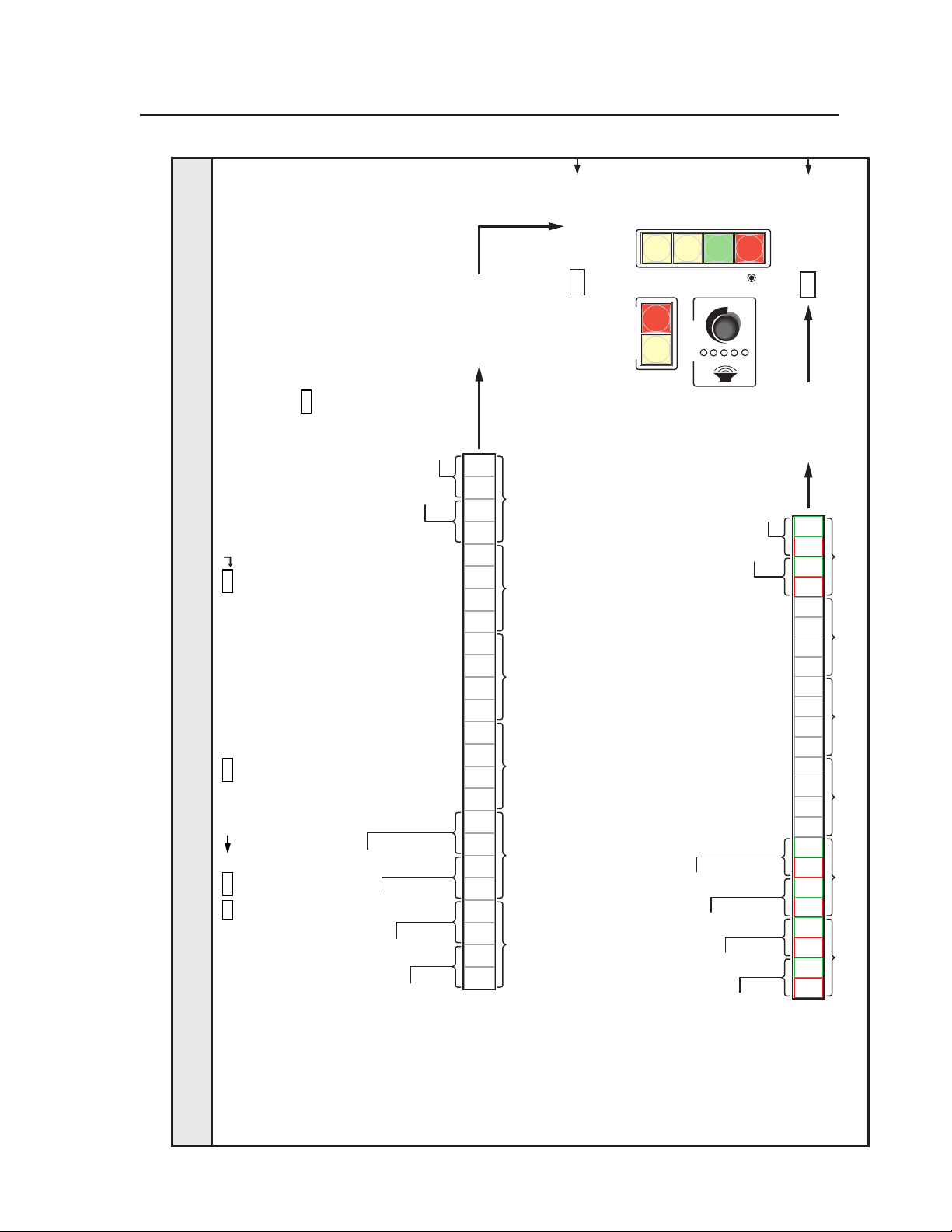
MLC 104 IP Front Panel
009F000B
Esc
Insert number
into command.
zeros.
Add 2 leading
009F000B
Lse
|
LC
X212
LC W
X212
Esc
(host to switcher) (host to switcher) (switcher to host)
Input 1
Input 2
Input 3
Power Off
to hex.
Hex NibbleHex Nibble
0
Hex Nibble
0
Hex Nibble
0
Powe r On
Power Off
XXXXXXXX
Convert
1101000000000000
B
Hex Nibble
0
Hex Nibble
0
Hex Nibble
0
Hex Nibble
PRELIMINARY
11111001
F
Input 1
Input 2
Hex Nibble Hex Nibble
Input 3
Hex Nibble
9
Hex Nibble
Input 4
Binary bit map for
button LED
status
Command/response table for SIS commands (continued)
Button LED control
Command ASCII (Telnet) URL Encoded (Web) Response Additional description
Example
Light buttons:
• Power On = amber
• Power Off = red
• Inputs 1, 2 = amber
• Input 3 = green
• Input 4 = red
Input 4
5-29MLC 104 Series • SIS™ Programming and Control
Page 30

SIS™ Programming and Control, cont’d
not affect IP settings or flash memory.
PRELIMINARY
X212
X212
Lbk*1*
X212
|
LX
X212
|
|
LX W 1%2A
X212
LC W LC
1*
1LX W 1LX
Esc
Esc
(host to switcher) (host to switcher) (switcher to host)
Esc
X212
Lbk*2*
|
LX
X212
LX W 2%2A
X212
2*
Esc
X212
|
2LX W 2LX
Esc
does
Zpf
Zpx The “reset all settings” command
|
|
ZFFF WZFFF
ZXXX WZXXX
24
Esc
Esc
command resets everything (all settings,
adjustments, PINs, the IP address, and
Zpq Reset all settings/memories. The ZQQQ
|
ZQQQ WZQQQ
Esc
subnet mask) to the factory default values.
Files in flash memory are also erased by this
command. The firmware version doesn’t
change.
The IP address is reset to 192.168.254.254,
the subnet mask is reset to 255.255.0.0. This
command is identical to reset mode 5,
discussed in “Resetting the unit” in chapter 2.
24
24
24
The command to make a button LED blinik fast takes precedence over the comand to make it blink slowly. If a button’s LEDs are set to blink both fast and slowly, the LED will
blink fast.
Read button LED status
Set button LEDs to blink slowly
Read which button LEDs are set to blink (whether slowly or fast)
Set button LEDs to blink fast
Command/response table for SIS commands (continued)
Command ASCII (Telnet) URL Encoded (Web) Response Additional description
Read which button LEDs are set to blink fast
Erase the flash memory
Reset all device settings to factory defaults
Reset (zap) commands and erase commands
24
The ZXXX command does not reset any IP-related settings such as the IP address, subnet mask, and gateway IP address. It also does not affect user files stored in flash memory.
Absolute system reset
MLC 104 Series • SIS™ Programming and Control5-30
Page 31

The syntax for setting a special function for an MLC is X? * __ # where X? is the value and __ is the
function number. To view a function’s setting, use __#, where __ is the function number. In the
X?
following table the values of the
variable are different for each command/function. These values
are given in the rightmost column.
Command/response table for special function SIS commands
(accessible via RS-232 only)
Command ASCII Command Response
(host to MLC) (MLC to host) and additional descriptions
X?
values
Delay times
Most projectors require a certain amount of time during warm-up and cool-down during which they do not accept
commands. Once you have set the input selction lock during power on/off command (53#, page 5-35), send this
command (1#) to specify the amount of time for the MLC to wait between sending the projector a power-on or power-off
command and when the next input button press can occur.
Power on delay
Example: 8*1# WarmUp*008 Example: set a 16 second power on delay.
Example: 1# WarmUp*023 Example: view the power on delay
Power off delay
Example: 23*2# CoolDown*023 Example: set a 46 second power off
Power off button delay
24
24
24
X?
*1 # WarmUp* X? 0 = 0 seconds,
1 = 2 seconds,
2 = 4 seconds,
... in 2 second steps up to
150 = 300 seconds (5 minutes).
setting.
X?
*2 # CoolDown* X? 0 = 0 seconds,
1 = 2 seconds,
2 = 4 seconds,... in 2 second
steps up to 150 = 300 seconds.
delay.
X?
*22 # PwrOffDly* X? 0 = the power off button
requires no hold delay (default),
1 = the power off button
requires a 2-second hold delay
before starting the power-off
sequence.
PRELIMINARY
Audio settings
24
Limit audio level on display power-on
The MLC responds with an E14 error code when volume mode = 1 (increment/decrement).
The maximum X? is limited by the maximum volume setting (47#). You must set the maximum volume (47#
command) before setting the limit audio level feature (11# command). See page 5-34.
Example: 28*11# VolLimit*028 Example: limit power-up volume
X?
*11 # VolLimit* X? If this feature is enabled, the
maximum initial power-up
volume level does not exceed
the level specified by this
command.
0 = audio off, ...,
20 = default value, ...,
100 = no limit on audio level at
power-on.
to 70% of maximum volume.
MLC 104 Series • SIS™ Programming and Control
5-31
Page 32

SIS™ Programming and Control, cont’d
Command/response table for special function SIS commands, continued
Command ASCII Command Response
(host to MLC) (MLC to host) and additional descriptions
Miscellaneous settings
Enable switcher slaving
Volume knob mode
Max. volume
24
24
Maximum volume cannot be changed while an MLS switcher is detected at the MLC’s MLS slave switcher port.
When the maximum volume is changed, the volume level and the volume limit during display power-up (11#) are set
to 25% of the new maximum volume setting.
X?
*41 # Slave*X? For X?,
X?
*46 # VolMode*X? For X?,
X?
*47 # VolMax*X? For maximum volume,
X?
values
0 = disable control of a slaved
Extron MLS switcher,
1 = enable (default) MLS slaved
switcher control
0 = discrete volume values
1 = continuous increment/
decrement.
X?
is 1 to 100.
40 = stand-alone MLC default,
100 = default for an MLC with a
slaved, detected MLS switcher.
PRELIMINARY
5-32
MLC 104 Series • SIS™ Programming and Control
Page 33

Command/response table for special function SIS commands, continued
Command ASCII Command Response
X?
values
(host to MLC) (MLC to host)) and additional descriptions
Button press/release emulation
Emulating a button press or release causes the commands and actions that are associated with the button via the main
event script to be executed. Button emulation triggers only what has been set up via the Button Config. part of the
Windows-based configuration program or via Global Configurator 2.0 or higher. Emulation does not trigger the built-in
SIS input switching commands (
See the diagrams below and on the next page to determine the number of the memory block associated with each button.
The input button register numbering shown in the following illustrations is for a stand-alone MLC.
MLC 104 IP,
MLC 104,
or
SCP 104
Front
X200
!) or the projector power on/off commands (1P or 0P).
Button/Switch Memory Block Numbering for the
MLC 104 Series, SCP 104 Series, and IR 402
1 2
PROJECTOR
ON
VOLUME
OFF
CONFIG
VIDEO
AUX
VIDEO
PC
IMAGE
MUTE
1
2
3
4
MLC 104 IP
9
10
11
12
25 24
Clock-
Counter-
wise
clockwise
CONFIG
HOST/
Tx
Rx
GROUND
Tx/IR
PROJECTOR
Rx
RS-232/IR
GROUND
PWR SNS
GROUND
+12V OUT
A B E
COMM
+V
SCP
G
MLS PWR
SCP
A B
RS-232 12V
Rx
Tx
GROUND
GROUND
+12V IN
MLC 104 IP
Right Side
(rotated)
LAN
TWEEKER TO REMOVE
PRESS TAB WITH
106
Power Sense/
Digital Input
Emulate a button/switch press
X?
*42 # SwPrs*X? This command causes the MLC
to issue the commands
associated with a button press.
X?
= the number of the memory
block for the button/switch for
which you want to emulate a
press (1 - 128).
Emulate a button/switch release
X?
*43 # SwRls*X? This makes the MLC issue the
commands associated with a
button release.
X?
= the button’s/switch’s
memory block number.
Emulate a button press-and-releaseX? *44 # SwCmd*X? The MLC issues the commands
associated with both the press and
the release of the specified button.
X?
= the button’s/switch’s
memory block number.
PRELIMINARY
MLC 104 Series • SIS™ Programming and Control
5-33
Page 34

SIS™ Programming and Control, cont’d
Command/response table for special function SIS commands, continued
PRELIMINARY
Command ASCII Command Response
(host to MLC) (MLC to host) and additional descriptions
X?
values
Button control
Set slave map
24
Example: 6*34# SlaveMap4*6 Map input 6 (an input on a
Set and trigger a button press repeat
Example: 9*850*45# RptRate*9*850 The commands associated with
The button repeat SIS command (X? * Y? *45 #) must be entered each time you want to have a button press trigger
repeated command releases. Also, only one button at a time can be set to repeat: multiple buttons can not be in repeat
mode simultaneously.
The Repeat while held every... feature found in the configuration software (in the Button Config. tab) and Global
Configurator 2 is based on this command. However, through scripting the MLC sets the repeat mode on in response to
a specific button press, and it sets the repeat mode to 0 when the button is released or input is no longer selected.
X?
* 3Y? # SlaveMapY? *
values values
X? Y?
Default: X? = Y?
00 = input 0
01 = input 1
02 = input 2
...
98 = input 98
99 = input 99
X?
* Y? *45 # RptRate*X? *
1 = input button 1
2 = input button 2
3 = input button 3
4 = input button 4
X? X?
Y?
is the actual input channel
(including inputs on a slaved
switcher) to select when button
Y?
is pressed. The values for
these variables are shown at left.
slaved switcher) to the MLC’s
input button 4. When button 4
is pressed, the A/V system
switches to input 6, and any
instructions (DVD or VCR
control commands, for example)
associated with input button 4
on the MLC are executed.
This command tells the MLC to
repeat a specific button’s
commands at a fixed interval (a
set frequency).
X?
= the number of the button/
switch (1 - 128). See the
diagram on page 5-34.
Y?
is the repeat interval: 0 to
65535, in 20 ms steps.
1 = 20 ms, 2 = 40 ms, 3 = 60 ms,...
65535 = 1,310,700 ms = 21.845
minutes.
If Y? = 0, the MLC stops
repeating the selected button’s
commands.
the input 1 button are executed
every 850x20 ms (= 17,000 ms =
17 seconds) until the repeat rate
for that button is set to 0
(“cleared”).
X?
Query button repeat rate status 45#
Y?
*
See the variables for the
command shown above.
Clear (turn off) the button repeat240*0*45# RptRate*000*00000 This command clears the button
repeat setting and turns off the
button repeat function.
5-34
MLC 104 Series • SIS™ Programming and Control
Page 35

Command/response table for special function SIS commands, continued
Command ASCII Command Response
X?
and
Y?
values
(host to MLC) (MLC to host) and additional descriptions
Front panel button LED control
Query button LED control status
X?
* Y? *51 # Lmp Y? * X?
values values
X? Y?
0 = all LEDs are off
1 = green LED is on
2 = red LED is on
3 = green & red LEDs are
on (button glows amber)
4 = slowly blinking green
5 = slowly blinking red
6 = slowly blinking amber
7 = fast blinking green
8 = fast blinking red
9 = fast blinking amber
Y?
* 51 #
1 = power on button
2 = power off button
9 = input button 1
10 = input button 2
11 = input button 3
12 = input button 4
X?
See the variables for the
X?
is the LED state,
Y?
is which projector power,
input, or room/function button
to control. See the list of values
at left.
24
command shown above.
Front panel lockout
Lock out input selection during power-on/power off
X?
* 53 # PwrLock * X? For X?:
This command applies to input selection buttons in the switching rotation only (input buttons that are not controlled
by scripts).
24
Input switching lockout duration
X?
* 54 # IODelay * X? This command locks out
This command applies to input selection buttons in the switching rotation only (input buttons that are not controlled
by scripts).
Example: 25*54# IODelay*25 Inputs cannot be switched for
Enable PIN
24
X?
* 60 # PINEnable * X? For X?,
PIN access can be used only while display power is off.
Set PIN
24
X?
* Y? * 61 # PINNum * X? * Y? For X?,, 0 = administrator level,
24
0 = off (default)
1 = on
(prevents changes to) input
switching for the specified
duration after an input has been
switched. X? is the lockout
duration of from 0 to 65535, in
20 ms steps.
1 = 20 ms, 2 = 40 ms, 3 = 60 ms,...
65535 = 1,310,700 ms = 21.845
minutes. Default = 25 = 0.5 s.
0.5 seconds after an input
change.
0 = personal identification
number (PIN) access is enabled
for all levels (administrator and
user)
1 = administrator PIN only is
enabled
2 = PIN access is disabled
(default)
1 = user level.
For Y?, the PIN is any 4-digit
combination of the numbers 1
through 4.
Administrator default PIN =
1423.
User default PIN = 0
PRELIMINARY
MLC 104 Series • SIS™ Programming and Control
5-35
Page 36

SIS™ Programming and Control, cont’d
Command/response table for special function SIS commands, continued
Command ASCII Command Response
(host to MLC) (MLC to host) and additional descriptions
Query PIN
24
X?
* 61 #
Y?
For X?,, 0 = administrator level,
X?
1 = user level.
Y?
PIN.
Y?
and
is the corresponding 4-digit
values
PRELIMINARY
5-36
MLC 104 Series • SIS™ Programming and Control
 Loading...