

Page 1
Product Category
MGP Pro and WindoWall® Pro Series • Setup Guide
The MGP Pro and WindoWall Pro Series are multi-window video signal processors that can display multiple video sources
on a single screen in picture-in-picture or picture-by-picture format. The processors can switch among inputs and presets.
The available models are listed below. The MGP 464 Pro and WindoWall Pro models display up to four windows while the
MGP 462 Pro models display one or two.
The WindoWall Pro Series products are designed for videowall systems and are available in sets of two or three processors.
These models have no front panel controls and are controllable only via software.
The following input congurations are available:
z Standard MGP 464 Pro, MGP 462 Pro, and WindoWall Pro — Four sets of BNC inputs that accept RGB, component
video, S-video, and composite video signals
z MGP 464 Pro DI, MGP 462 Pro DI, and WindoWall Pro DI — Four sets of BNC inputs and four HDMI inputs
z MGP 464 Pro 3G-SDI and MGP 462 Pro 3G-SDI — Four sets of BNC inputs, two 3G/HD-SDI inputs, and two HDMI
inputs
All MGP Pro models have 15 virtual inputs on BNC connectors.
This guide provides procedures for installing all MGP 464 Pro and MGP 462 Pro models, and for conguring all models except the
WindoWall Pro series. To congure the WindoWall Pro models (done only using software), see the WindoWall Console help le or
the WindoWall Console Quick Reference card.
NOTE: For full installation, configuration, and operation details, see the MGP Pro Series User Guide or the WindoWall Pro
Series User Guide, available at www.extron.com.
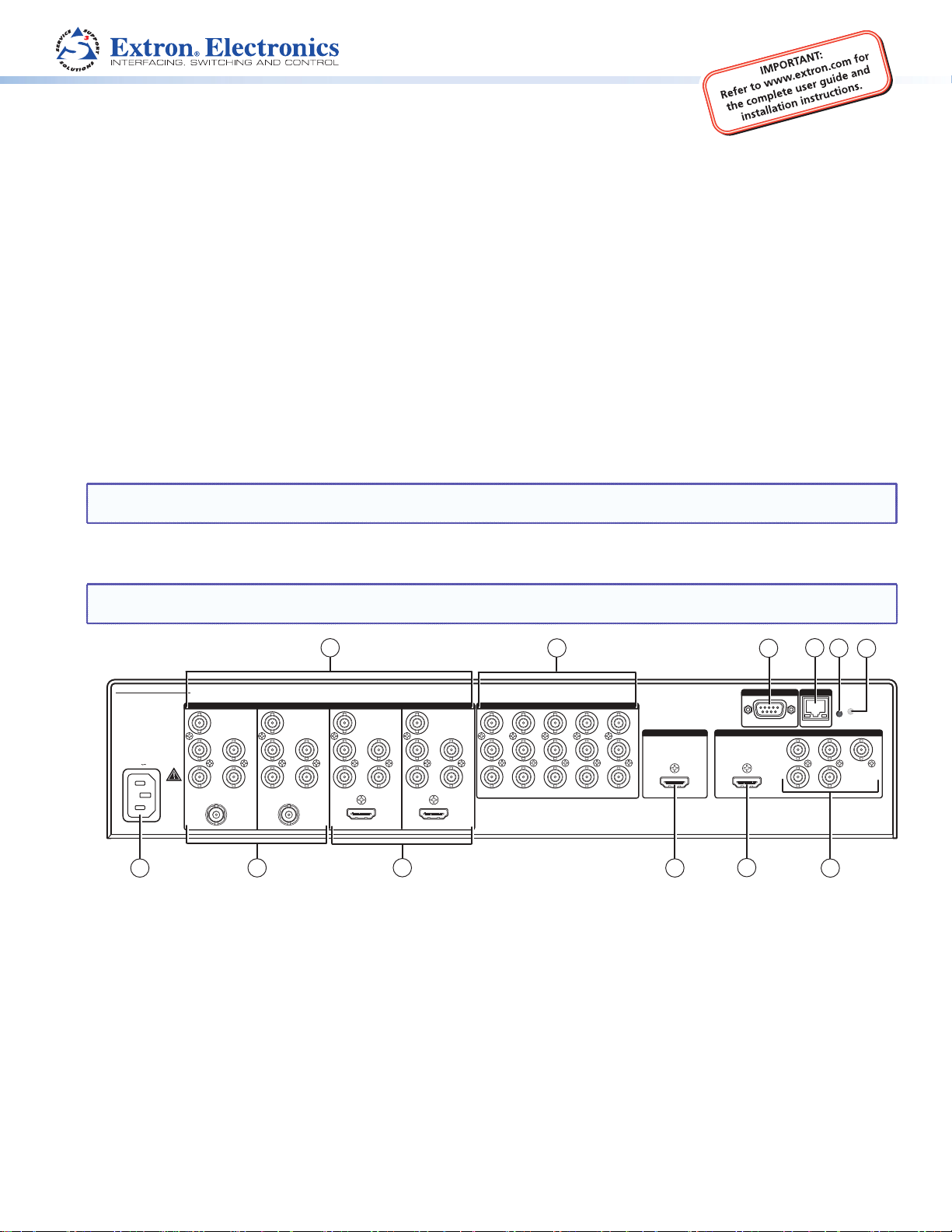
Rear Panel Features and Connections
NOTE: The illustration below shows an MGP 464 Pro 3G-SDI. The rear panels of the other MGP Pro and WindoWall Pro
models are the same except for the number and types of input connectors.
MGP/WINDOWALL PRO SERIES
1
100-240V
-A MAX
3G/HD-SDI3G/HD-SDI
50/60 Hz
12
BNC inputs 1 through 4
a
LAN connector
d
BNC output connectors
g
HDMI inputs (DI and SDI models only)
j
2
R
R-Y
G/Y
VID
B/C
B-Y
R
R-Y
G/Y
H/HV
VID
V
B/C
B-Y
11
INPUTS
H/HV
V
1
3
HDMI
4
R
R-Y
G/Y
VID
B/C
B-Y
R-Y
H/HV
G/Y
VID
V
B/C
B-Y
HDMI
5
R
VID
Y
6
H/HV
VID
B-Y
C
7
V
VID
R-Y
10
Virtual inputs 5 through 19
b
Reset button
e
HDMI output connector
h
3G/HD-SDI inputs (3G-SDI models only)
k
8
9
10
2
VIRTUAL INPUTS
11
VID
Y
12
VID
B-Y
C
13
VID
R-Y
3
14
17
VID
VID
Y
15
VID
B-Y
C
16
VID
R-Y
VID
Y
Y
VID
B-Y
C
VID
R-Y
BACKGROUND
HDMI HDMI
18
VID
B-Y
C
19
VID
R-Y
9
Remote RS-232/422 connector
c
Reset LED
f
HDMI live background input
i
AC power connector
l
RS-232/422
8
Installation Steps
OUTPUTS
4
5
6
LANREMOTE
RESET
B/
G/Y
R/
R-Y
H/
HV
B-Y
V
7
1. Install the four rubber feet on the bottom of the MGP Pro, or mount the unit using the supplied rack mounting brackets (see
the instructions provided with the mounting kit).
2. Turn off power to the input and output devices, and remove the power cords from them.
1
Page 2
MGP Pro and WindoWall® Pro Series • Setup Guide (Continued)
3. Connect input sources to the BNC, HDMI, and 3G/HD-SDI input connectors. The inputs can accept the following signals:
z RGB, HD/SD component, S-video, and composite video inputs 1, 2, 3, and 4 — RGB, component video,
S-video, or composite video (fully congurable)
11111
R/R-Y
G/Y
VID
B/C
B-Y
RGBHV
Video
H/HV
V
R/R-Y
G/Y
VID
B/C
B-Y
RGBS or
RGBcvS
Video
H/HV
V
RGsB or
Component
R/R-Y
G/Y
VID
B/C
B-Y
Video
H/HV
V
S-Video Composite
R/R-Y
G/Y
VID
B/C
B-Y
H/HV
V
R/R-Y
G/Y
VID
B/C
B-Y
z HDMI inputs 1, 2, 3, and 4 (DI and SDI models only) — Any of these inputs can be used instead of or in combination
with analog inputs 1 through 4. However, the MGP Pro cannot process input from two different source devices
connected to HDMI or 3G-SDI and BNC connectors with the same input number (for example, input 1) at the same time.
z 3G-SDI inputs 1 and 2 (SDI models only) — Either of these inputs can be used instead of or in combination with
analog input 1 or 2.
NOTE: Standard definition SDI is not supported on these 3G/HD-SDI inputs.
z Live Background input — HDMI for live background video only (available on all models). The two or four MGP Pro
windows are displayed in front of this background image. When a live background is used, the MGP Pro output is locked
to the input rate of the live background. This input is not scaled.
NOTE: This input connector can be used only to receive the background image. The input is not scaled or
processed. To process HDMI input signals, you must use a DI or SDI model.
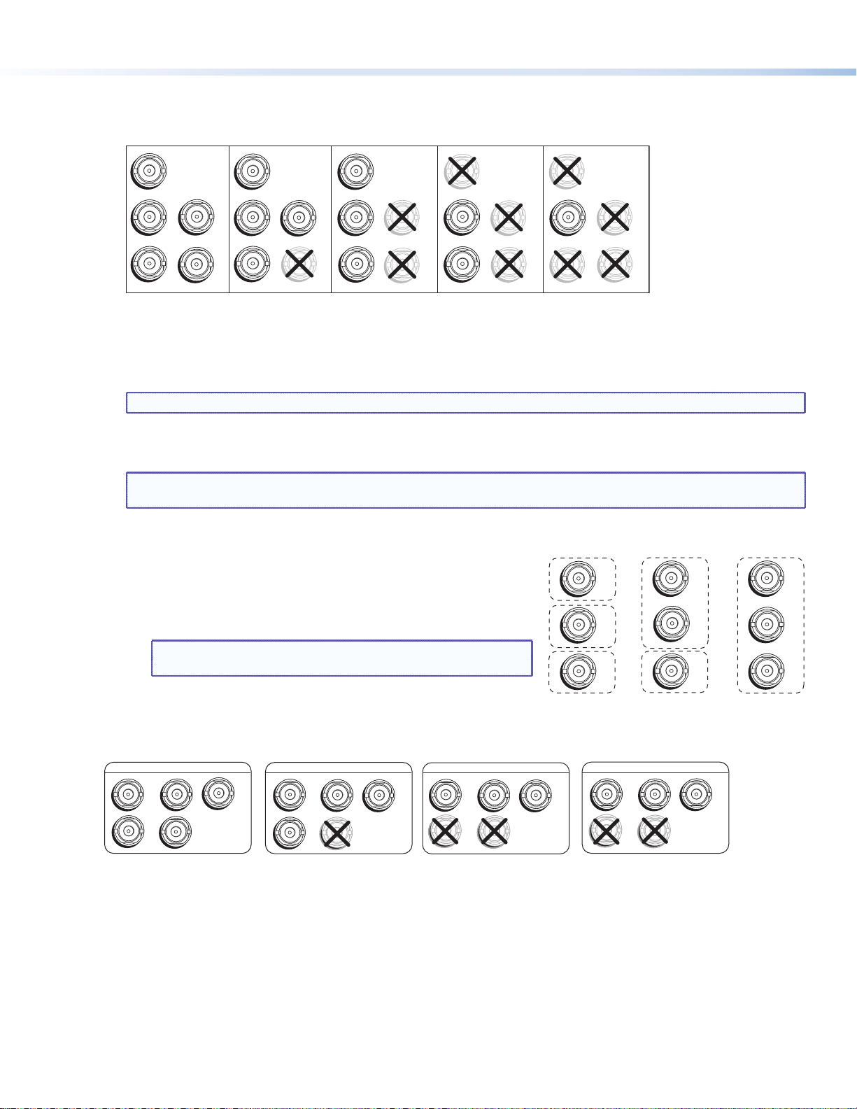
z Virtual inputs (not supported on WindoWall Pro models) — Component
video, S-video, or composite video. These virtual inputs can be
congured only via the Windows-based control software or SIS (Simple
Instruction Set) commands. In each column of connectors, you can
connect inputs as follows:
z Three composite video
z One S-video and one composite video
NOTE: The S-video input must be connected to the top two
BNC connectors in the column (Y on top, C second).
Composite
5
6
7
VID
VID
B-Y
VID
R-Y
Y
C
z One interlaced component video (connects to all three BNC
connectors in the column)
4. Attach an output device to the analog BNC connectors (shown below) or to the HDMI output connector.
RGBHV
RGBS
RGsB
HD YUV Component Video
Video
H/HV
V
S-video and
Composite
5
6
7
VID
VID
B-Y
VID
R-Y
Y
C
Component
5
6
7
R-Y
VID
VID
B-Y
VID
Y
C
R
/R-Y
H
/HV
G
B
/Y
/B-Y
V
R
/R-Y
H
/HV
G
B
/Y
/B-Y
V
R
/R-Y
H
/HV
G
B
/Y
/B-Y
V
R
/R-Y
H
/HV
G
B
/Y
/B-Y
V
5. If the MGP Pro will be connected to a computer or to a host controller for remote control, connect an RS-232 cable from the
host to the 9-pin D RS-232/422 rear panel connector or the front panel 2.5 mm TRS Cong port. The default protocol for both
ports is 9600 baud, 1 stop bit, no parity, 8 data bits, and no ow control.
Alternatively, you can connect an RJ-45 network cable to the rear panel LAN port for remote control.
6. Connect power to the MGP Pro by plugging a standard IEC power cord (provided) from a 100 to 240 VAC, 50-60 Hz power
source into the power receptacle (l on the rear panel diagram on page 1).
7. Connect power to all other devices and power them on.
2
Page 3

Product Category
Front Panel Buttons (Non-WindoWall Pro Models Only)
The MGP 464 Pro (shown below) and MGP 462 Pro front panels contain the following buttons to control and congure the
MGP Pro. When you press a button, the LCD panel displays the settings that you can change.
1
2
3
4
5
6
7
VIRTUAL INPUTS
FREEZE
1234
INPUTS
5
679
8
10
11
12
13
14
15
16
Freeze — Freeze the input in the currently selected window. To unfreeze the input, press this button again.
a
Inputs 1, 2, 3, and 4 — Select fully congurable inputs 1 through 4. On the MGP Pro DI models, these buttons can also
b
17
18
19
WINDOW SELECT
1 2
1
3 4
PRESET
RECALL
/SAVE
ENTER
WINDOW/
IMAGE
SIZE
WINDOW/
IMAGE
POSITION
CONFIG
10
BRIGHT
/CONT
COLOR
/TINT
DETAIL
WINDOW/
IMAGE
ZOOM
MENU
ADJUST
NEXT
MGP 464 Pro
MULTI-GRAPHIC PROCESSOR
9
8
select the four HDMI inputs. On the MGP Pro 3G-SDI models, input buttons 1 and 2 can select the SDI inputs and buttons
3 and 4 can select the HDMI inputs. To mute (turn off) the input in a window, press its button twice (or once, if the button is
already lit). The button ashes while the input is muted.
Virtual Inputs (5 through 19) — Select virtual inputs 5 through 19. These inputs can be
c
congured via control software or SIS commands to accept S-video, composite video, or
standard denition component video only.
Window Select — Select a window to freeze and unfreeze, mute and unmute, select an
d
input for, or to adjust using Picture Control buttons. The MGP 464 Pro models have four of
these buttons and the MGP 462 Pro models have two.
Preset Recall/Save and Enter — In combination, save the current settings to memory
e
(preset) or recall a stored preset (up to 128).
Picture controls — Adjust window and image size, position, brightness, contrast, detail
f
(sharpness), color, tint, and zoom. Use the horizontal ([) and vertical ({) Adjust knobs to
adjust the settings shown on the left and right sides of the LCD screen, respectively.
LCD screen — Displays messages, menu information, and your selections.
g
Horizontal and vertical Adjust knobs — Turn these knobs to scroll through submenu
h
options and preset memory slots, and to adjust picture controls.
Menu navigation buttons — Press Menu to step through the menus. From each menu,
i
press Next to step through its submenus.
Config port — RS-232 port that is an alternative to the rear panel RS-232/422 port but
j
does not support RS-422
Setting Up the MGP Pro Using the Front Panel
After you have installed and connected the MGP Pro, use the MGP Pro front panel to congure
and adjust the unit for use. If installing a WindoWall Pro, see the WindoWall Console help le or
the WindoWall Console Quick Reference card for information on conguring via software.
Press the Menu button to access the Main menu (shown at right). Then, repeatedly press
the Menu button to cycle through the menus and access the Input Conguration, Output
Conguration, and Advanced Conguration menus to perform steps 1 through 4.
1. Use the Input Conguration menu to congure inputs 1 through 4.
NOTE: The virtual inputs (5 through 19) can be configured only via the
Windows-based control software or SIS commands.
2. Use the Output Conguration menu to congure the output signal type and the output rate
for the desired resolution.
3. From the Advanced Conguration menu, Test Pattern submenu, select the Alternating Pixels (Alt. Pixels) test pattern. Adjust
the active pixels, total pixels, and pixel phase settings of your display for optimal picture quality.
3
Page 4

4. From the Advanced Conguration menu, change the test pattern to Crop and adjust the positioning of your display until all
four sides of the crop pattern are visible.
5. Select input 1 for all windows on the processor.
6. Perform an Auto-Image adjustment.
a. Press the Menu button once to access the Auto-Image menu.
b. Press Next and use the Adjust knobs to select a window.
c. Press Next again to initiate the adjustment.
d. Repeat for all inputs on the MGP Pro.
7. Use the Input Conguration menu to make any desired advanced adjustments, including Horizontal and Vertical Start, Pixel
Phase, Total Pixels, Active Pixels, and Active Lines.
8. Use the Picture Controls to size and position each window as desired for your application
9. Save your conguration as a window preset (see below).
10. Size and position windows as desired for each of your applications. Save each one to any of the remaining 127 window
preset names for easy recall of window settings (see below).
Saving and Recalling Presets
To save the current conguration as a preset:
1. Press and hold the Preset Recall/Save button until the LCD screen displays Window Preset/Save to #nnn.
2. Rotate either Adjust knob to select the preset number or name to which you want to save this conguration.
3. Press the Enter button.
To recall and apply a saved preset, press the Preset Recall/Save button and immediately release it. The LCD window displays
Window Preset/Recall #nnn. Rotate either Adjust knob to select a preset number, then press Enter.
SIS (Simple Instruction Set) Commands
As an alternative to the front panel controls, you can issue SIS commands via RS-232, RS-422, or Ethernet from your computer to
set up the processor (see your MGP Pro or WindoWall Pro user guide at www.extron.com for a complete list of SIS commands).
Command ASCII (Telnet) Response Additional Description
Select an input
Mute (blank) a window
Unmute a window
Perform Auto-Image
Save window preset
Recall window preset
Set IP address
Read IP address
Set subnet mask
Read subnet mask
Set gateway address
Read gateway address
X!
= Input number (1-19)
X@
= Window number (1-2 or 1-4). 0 = all windows (mute, input selection, and freeze only)
X1$
= Window preset number (1-128)
X10&
= IP address (nnn.nnn.nnn.nnn). Leading zeros are optional in each octet.
X11#
= Subnet mask (nnn.nnn.nnn.nnn). Leading zeros are optional in each octet.
X!
* X@ ! Out
X@
* 1B
X@
* 0B
X@
55
*
# Img X@
X1$
2 *
2
E X10&
E
E X11#
E
E X10&
E
*
X1$
CI
CS
CG
,
.
}
}
}
CI
CS
CG
}
}
}
X@
X@
Blk1
X@
Blk0
*
Spr2
Rpr2 *
Ipi •
X10&
]
Ips •
X11#
]
Ipg •
X10&
]
* In X!
]
]
]
X1$ ]
X1$ ]
X10& ]
X11# ]
X10& ]
]
Select input
X!
in window X@.
Blank (mute) window X@.
Unmute window
X@
.
Perform Auto-Image on input in window X@.
).
X11#
X1$
).
Save window settings as preset
Recall window preset
Set unit IP address
View the unit IP address (
Set unit subnet mask
View the unit subnet mask (
Set IP address
View the gateway IP address for your unit.
X10&
X1$
.
X10&
(nnn.nnn.nnn.nnn)
X10&
X11#
(nnn.nnn.nnn.nnn)
for your gateway.
.
Extron Headquarters
+1.800.633.9876 (Inside USA/Canada Only)
Extron Europe
+31.33.453.4040
© 2013 Extron Electronics — All rights reserved. All trademarks mentioned are the property of their respective owners. www.extron.com
4
Extron Asia
+65.6383.4400
Extron Japan
+81.3.3511.7655
Extron China
+86.21.3760.1568
Extron Middle East
+971.4.299.1800
Extron Korea
+82.2.3444.1571
Extron India
+91.80.3055.3777
68-2469-50
Rev. A 06 13
 Loading...