

Page 1

MediaPort 200
HDMI and Audio to USB Scaling Bridge
User Guide
Scalers
68-2755-01 Rev. C
12 16
Page 2

Safety Instructions
Safety Instructions • English
WARNING: This symbol, , when used on the product, is intended to
alert the user of the presence of uninsulated dangerous voltage within
the product’s enclosure that may present a risk of electric shock.
ATTENTION: This symbol, , when used on the product, is intended
to alert the user of important operating and maintenance (servicing)
instructions in the literature provided with the equipment.
For information on safety guidelines, regulatory compliances, EMI/EMF
compatibility, accessibility, and related topics, see the Extron Safety and
Regulatory Compliance Guide, part number 68-290-01, on the Extron
website, www.extron.com.
Sicherheitsanweisungen • Deutsch
WARNUNG: Dieses Symbol auf dem Produkt soll den Benutzer
darauf aufmerksam machen, dass im Inneren des Gehäuses dieses
Produktes gefährliche Spannungen herrschen, die nicht isoliert sind und
die einen elektrischen Schlag verursachen können.
VORSICHT: Dieses Symbol auf dem Produkt soll dem Benutzer in
der im Lieferumfang enthaltenen Dokumentation besonders wichtige
Hinweise zur Bedienung und Wartung (Instandhaltung) geben.
Weitere Informationen über die Sicherheitsrichtlinien, Produkthandhabung,
EMI/EMF-Kompatibilität, Zugänglichkeit und verwandte Themen finden Sie in
den Extron-Richtlinien für Sicherheit und Handhabung (Artikelnummer
68-290-01) auf der Extron-Website, www.extron.com.
Instrucciones de seguridad • Español
ADVERTENCIA: Este símbolo, , cuando se utiliza en el producto,
avisa al usuario de la presencia de voltaje peligroso sin aislar dentro del
producto, lo que puede representar un riesgo de descarga eléctrica.
ATENCIÓN: Este símbolo, , cuando se utiliza en el producto, avisa
al usuario de la presencia de importantes instrucciones de uso y
mantenimiento recogidas en la documentación proporcionada con el
equipo.
Para obtener información sobre directrices de seguridad, cumplimiento
de normativas, compatibilidad electromagnética, accesibilidad y temas
relacionados, consulte la Guía de cumplimiento de normativas y seguridad
de Extron, referencia 68-290-01, en el sitio Web de Extron, www.extron.com.
Instructions de sécurité • Français
AVERTISSEMENT : Ce pictogramme, , lorsqu’il est utilisé sur le
produit, signale à l’utilisateur la présence à l’intérieur du boîtier du
produit d’une tension électrique dangereuse susceptible de provoquer
un choc électrique.
ATTENTION : Ce pictogramme, , lorsqu’il est utilisé sur le produit,
signale à l’utilisateur des instructions d’utilisation ou de maintenance
importantes qui se trouvent dans la documentation fournie avec le
matériel.
Pour en savoir plus sur les règles de sécurité, la conformité à la
réglementation, la compatibilité EMI/EMF, l’accessibilité, et autres sujets
connexes, lisez les informations de sécurité et de conformité Extron, réf.
68-290-01, sur le site Extron, www.extron.com.
Istruzioni di sicurezza • Italiano
AVVERTENZA: Il simbolo, , se usato sul prodotto, serve ad
avvertire l’utente della presenza di tensione non isolata pericolosa
all’interno del contenitore del prodotto che può costituire un rischio di
scosse elettriche.
ATTENTZIONE: Il simbolo, , se usato sul prodotto, serve ad
avvertire l’utente della presenza di importanti istruzioni di funzionamento
e manutenzione nella documentazione fornita con l’apparecchio.
Per informazioni su parametri di sicurezza, conformità alle normative,
compatibilità EMI/EMF, accessibilità e argomenti simili, fare riferimento
alla Guida alla conformità normativa e di sicurezza di Extron, cod. articolo
68-290-01, sul sito web di Extron, www.extron.com.
Instrukcje bezpieczeństwa • Polska
OSTRZEŻENIE: Ten symbol, , gdy używany na produkt, ma na celu
poinformować użytkownika o obecności izolowanego i niebezpiecznego
napięcia wewnątrz obudowy produktu, który może stanowić zagrożenie
porażenia prądem elektrycznym.
UWAGI: Ten symbol, , gdy używany na produkt, jest przeznaczony do
ostrzegania użytkownika ważne operacyjne oraz instrukcje konserwacji
(obsługi) w literaturze, wyposażone w sprzęt.
Informacji na temat wytycznych w sprawie bezpieczeństwa, regulacji
wzajemnej zgodności, zgodność EMI/EMF, dostępności i Tematy pokrewne,
zobacz Extron bezpieczeństwa i regulacyjnego zgodności przewodnik, część
numer 68-290-01, na stronie internetowej Extron, www.extron.com.
Инструкция по технике безопасности • Русский
ПРЕДУПРЕЖДЕНИЕ: Данный символ, , если указан
на продукте, предупреждает пользователя о наличии
неизолированного опасного напряжения внутри корпуса
продукта, которое может привести к поражению
электрическим током.
ВНИМАНИЕ: Данный символ, , если указан на продукте,
предупреждает пользователя о наличии важных инструкций
по эксплуатации и обслуживанию в руководстве,
прилагаемом к данному оборудованию.
Для получения информации о правилах техники безопасности,
соблюдении нормативных требований, электромагнитной
совместимости (ЭМП/ЭДС), возможности доступа и других
вопросах см. руководство по безопасности и соблюдению
нормативных требований Extron на сайте Extron: ,
www.extron.com, номер по каталогу - 68-290-01.
安全说明 • 简体中文
警告: 产品上的这个标志意在警告用户该产品机壳内有暴露的危险 电压,
有触电危险。
注意: 产品上的这个标志意在提示用户设备随附的用户手册中有
重要的操作和维护(维修)说明。
关于我们产品的安全指南、遵循的规范、EMI/EMF 的兼容性、无障碍
使用的特性等相关内容,敬请访问 Extron 网站 , www.extron.com,参见
Extron 安全规范指南,产品编号 68-290-01。
Page 3

安全記事 • 繁體中文
警告: 若產品上使用此 符號,是為了提醒使用者,產品機殼內存在著
可能會導致觸電之風險的未絕緣危險電壓。
注意 若產品上使用此符號,是為了提醒使用者,設備隨附的用戶手冊中有
重要的操作和維護(維修)説明。
有關安全性指導方針、法規遵守、EMI/EMF 相容性、存取範圍和相關主題的詳細資
訊,請瀏覽 Extron 網站:www.extron.com,然後參閱《Extron 安全性與法規
遵守手冊》,準則編號 68-290-01。
安全上のご注意 • 日本語
警告: この記 号 が製品上に表示されている場合は、筐体内に絶縁されて
いない高電圧が流れ、感電の危険があることを示しています。
注意:この記号 が製品上に表示されている場合は、本機の取扱説明書
に 記載されている重要な操作と保守( 整備)の 指示についてユーザーの
注意を喚起するものです。
安全上のご注意、法規厳守、EMI/EMF適合性、その他の関連項目に
つ い て は 、エ ク スト ロ ンの ウェブ サ イト www.extron.com よ り 『 Extron Safety
and Regulatory Compliance Guide』 ( P/N 68-290-01) をご覧ください。
안전 지침 • 한국어
경고: 이 기호 가 제품에 사용될 경우, 제품의 인클로저 내에 있는
접지되지 않은 위험한 전류로 인해 사용자가 감전될 위험이 있음을
경고합니다.
주의: 이 기호 가 제품에 사용될 경우, 장비와 함께 제공된 책자에 나와
있는 주요 운영 및 유지보수(정비) 지침을 경고합니다.
안전 가이드라인, 규제 준수, EMI/EMF 호환성, 접근성, 그리고 관련 항목에
대한 자세한 내용은 Extron 웹 사이트(www.extron.com)의 Extron 안전 및
규제 준수 안내서, 68-290-01 조항을 참조하십시오.
Copyright
© 2016 Extron Electronics. All rights reserved.
Trademarks
All trademarks mentioned in this guide are the properties of their respective owners.
The following registered trademarks(
®
), registered service marks(
SM
), and trademarks(TM) are the property of RGBSystems, Inc. or
ExtronElectronics (see the current list of trademarks on the Terms of Use page at www.extron.com):
Registered Trademarks
(®)
Extron, AVTrac, Cable Cubby, ControlScript, CrossPoint, DTP, eBUS, EDID Manager, EDID Minder, Flat Field, FlexOS, Global Configurator,
GlobalScripter, GlobalViewer, Hideaway, Inline, IPIntercom, IPLink, KeyMinder, LinkLicense, LockIt, MediaLink, MediaPort, NetPA,
PlenumVault, PoleVault, PowerCage, PURE3, Quantum, SoundField, SpeedMount, SpeedSwitch, SystemINTEGRATOR, TeamWork,
TouchLink, V-Lock, VersaTools, VN-Matrix, VoiceLift, WallVault, WindoWall, XTP, and XTPSystems
Registered Service Mark
(SM)
: S3 Service Support Solutions
Trademarks (™
)
AAP, AFL (Accu-RateFrameLock), ADSP(Advanced Digital Sync Processing), Auto-Image, CableCover, CDRS(ClassD Ripple
Suppression), DDSP(Digital Display Sync Processing), DMI (DynamicMotionInterpolation), DriverConfigurator, DSPConfigurator,
DSVP(Digital Sync Validation Processing), eLink, Entwine, EQIP, FastBite, FOX, FOXBOX, IP Intercom HelpDesk, MAAP, MicroDigital,
Opti-Torque, ProDSP, QS-FPC(QuickSwitch Front Panel Controller), Room Agent, Scope-Trigger, ShareLink, SIS, SimpleInstructionSet,
Skew-Free, SpeedNav, Triple-Action Switching, True4K, Vector™ 4K , WebShare, XTRA, ZipCaddy, and ZipClip
Page 4

FCC Class A Notice
This equipment has been tested and found to comply with the limits for a Class A digital
device, pursuant to part15 of the FCC rules. The ClassA limits provide reasonable
protection against harmful interference when the equipment is operated in a commercial
environment. This equipment generates, uses, and can radiate radio frequency energy and,
if not installed and used in accordance with the instruction manual, may cause harmful
interference to radio communications. Operation of this equipment in a residential area is
likely to cause interference. This interference must be corrected at the expense of the user.
NOTE: For more information on safety guidelines, regulatory compliances, EMI/
EMF compatibility, accessibility, and related topics, see the “Extron Safety and
Regulatory Compliance Guide” on the Extron website.
Page 5

Conventions Used in this Guide
Notifications
The following notifications are used in this guide:
WARNING: Potential risk of severe injury or death.
AVERTISSEMENT : Risque potentiel de blessure grave ou de mort.
WARNING: Potential risk of severe injury or death.
AVERTISSEMENT : Risque potentiel de blessure grave ou de mort.
ATTENTION:
• Risk of property damage.
• Risque de dommages matériels.
NOTE: A note draws attention to important information.
TIP: A tip provides a suggestion to make working with the application easier.
Software Commands
Commands are written in the fonts shown here:
^AR Merge Scene,,Op1 scene 1,1 ^B 51 ^W^C
[01] R 0004 00300 00400 00800 00600 [02] 35 [17] [03]
E X! *X1&* X2)* X2#* X2! CE}
Computer responses and directory paths that do not have variables are written in the font
shown here:
Variables are written in slanted form as shown here:
Selectable items, such as menu names, menu options, buttons, tabs, and field names are
written in the font shown here:
Specifications Availability
Product specifications are available on the Extron website, www.extron.com.
Extron Glossary of Terms
A glossary of terms is available at http://www.extron.com/technology/glossary.aspx.
NOTE: For commands and examples of computer or device responses mentioned
in this guide, the character “0” is used for the number zero and “O” is the capital
letter “o.”
Reply from 208.132.180.48: bytes=32 times=2ms TTL=32
C:\Program Files\Extron
ping xxx.xxx.xxx.xxx —t
SOH R Data STX Command ETB ETX
From the File menu, select New.
Click the OK button.
Page 6

Contents
Introduction ...............................................1
About this Guide .................................................. 1
About the MediaPort 200 .................................... 1
Features .............................................................. 2
USB Video ........................................................... 5
Audio Functions................................................... 5
Application Diagrams ........................................... 6
Theory of Operation ................................... 7
MediaPort 200 Operational Modes ...................... 7
Speakerphones and AEC (Acoustic Echo
Cancellation) ....................................................... 8
Standalone Mode ................................................ 8
External DSP with AEC Mode .............................. 8
MediaPort 200 Signal Flow .................................. 9
Matrix Routing ................................................. 9
Mixing and Control......................................... 10
Master Volume Controls ................................. 13
Setting Audio Modes ......................................... 17
Standalone Mode .......................................... 17
External DSP with AEC Mode ........................ 17
Installation ............................................... 18
Rear Panel Connections .................................... 19
Securing the HDMI Connectors Using the
LockIt HDMI Lacing Brackets ........................... 23
Connecting for Remote Control ......................... 23
Connecting to the LAN Port ........................... 23
Connecting to the USB Config Port ............... 23
Connecting to the RS-232 Port ..................... 26
Configuring Windows for MediaPort 200 ........... 27
Configuring Skype for Business
(Microsoft® Lync®) for MediaPort 200 ................ 32
Product Configuration Software (PCS) ..... 34
Downloading the PCS Software ......................... 34
Starting the PCS Software ................................. 36
Updating Firmware via PCS ............................... 38
Input/Output Configuration Tab .......................... 40
HDMI Input .................................................... 41
HDMI Loop .................................................... 42
USB Output ................................................... 42
Test Patterns ................................................. 43
EDID Minder Tab ............................................... 43
Filter .............................................................. 44
Favorites ........................................................ 44
Connected Outputs ....................................... 44
Available EDID ............................................... 45
Input .............................................................. 45
Picture Config Tab ............................................. 46
Adjust Graphically .......................................... 47
Adjust Numerically ......................................... 48
Picture Controls ............................................. 49
Signal Sampling and Overscan ...................... 49
Input Presets ................................................. 50
Audio Config Tab ............................................... 51
Input Tab ....................................................... 51
Input DSP Window ........................................ 53
Mix Tab .......................................................... 56
Output Tab .................................................... 57
Preset and Digital I/O Tab .............................. 58
General Settings Tab ......................................... 59
Front Panel Operation ..............................61
Front Panel Features .......................................... 61
Powering On ..................................................... 62
Default Cycle ................................................. 62
Menus on the LCD Screen ................................ 63
Menu System Overview ................................. 63
Quick Setup Menu ......................................... 65
Input Presets Menu........................................ 66
Picture Control Menu ..................................... 68
Input Configuration Menu .............................. 70
Output Configuration Menu............................ 73
Audio Configuration Menu ............................. 74
viMediaPort 200 • Table of Contents
Page 7

Advanced Configuration Menu ....................... 76
View Comm Settings Menu ........................... 77
Edit Comm Settings Menu ............................. 78
Front Panel Lockout (Executive Mode) ............... 80
Resetting .......................................................... 80
No Signal Indicator (USB Output) ....................... 82
Video Presets .................................................... 82
Auto Memories .............................................. 82
Standalone MediaPort 200
Application Setup ....................................83
Overview ........................................................... 83
Video Input and Output ..................................... 83
HDMI Input .................................................... 83
HDCP-Compliant HDMI Loop-Out ................. 83
Mic/Line Input .................................................... 84
USB Communications Input .............................. 84
Audio Line Inputs ............................................... 84
USB Playback Input ....................................... 84
Line Input (analog) ......................................... 84
HDMI Input .................................................... 84
Audio Line Outputs ............................................ 85
Analog Line Output ........................................ 85
USB Line Output ........................................... 85
Ref and Aux Outputs ..................................... 85
Application Setup Example ................................ 86
Application 1 — Standalone
MediaPort 200 .............................................. 86
Gain Structure ............................................... 87
Input Tab ....................................................... 87
Mix Tab .......................................................... 87
Output Tab .................................................... 88
Sound Reinforcement System ........................... 88
Setting Mix and Listening Levels using the
PCS Software .................................................. 89
PCS Mix Screen ............................................ 89
Adjusting Mix Levels ...................................... 91
MediaPort 200 with External DSP
with AEC Application Setup ..................... 93
Overview ........................................................... 93
Video Input and Output ..................................... 93
HDMI Input .................................................... 93
HDCP-Compliant HDMI Loop-Out ................. 94
Mic/Line Input .................................................... 94
USB Communications Input .............................. 94
Audio Line Inputs ............................................... 94
USB Playback Input ....................................... 94
Line Input (analog) ......................................... 94
HDMI Input .................................................... 95
Audio Line Outputs ............................................ 95
Analog Line Output ........................................ 95
USB Line Output ........................................... 95
Ref and Aux Outputs ..................................... 95
Application Setup Examples .............................. 96
Application 1 — MediaPort 200 with
External DSP with AEC ................................. 96
DSP Routing for Application 1 ....................... 98
Control for Application 1 .............................. 100
Application 2 — MediaPort 200 with
External DSP with AEC with Hardware
and Software Codecs ................................. 102
DSP Routing for Application 2 ..................... 104
Control for Application 2 .............................. 106
Setting Mix and Listening Levels Using
the PCS Software .......................................... 108
PCS Mix Screen .......................................... 108
Adjusting Mix Levels .................................... 110
Remote Configuration and Control ........112
SIS Commands ............................................... 112
Power-Up Message ..................................... 112
MediaPort-Initiated Messages ...................... 113
Error Responses .......................................... 113
Using the Command and Response
Table........................................................... 114
Symbol Definitions ....................................... 114
Command and Response Table for SIS
Commands .................................................... 122
Input Configuration ...................................... 122
Picture Control ............................................. 123
Output Configuration ................................... 127
Advanced Configuration .............................. 129
Audio SIS Commands ..................................... 141
Audio Command Structure .......................... 141
Audio Command Symbol Definitions ............ 141
Command and Response Table for DSP
SIS Commands .............................................. 144
MediaPort 200 Web Page ............................... 149
Accessing the Web Page ............................. 149
Web Page Components .............................. 150
Special Characters ...................................... 155
Mounting ................................................156
Mounting Options ............................................ 156
MediaPort 200 • Table of Contents vii
Page 8

Introduction
This section provides an overview of the MediaPort 200 HDMI and Audio to USB Scaling
Bridge. The following topics are discussed:
• About this Guide
• About the MediaPort 200
• Features
• USB Video
• Audio Functions
• Application Diagrams
About this Guide
The MediaPort 200 User Guide describes the Extron MediaPort 200 HDMI and Audio to
USB Scaling Bridge and provides instructions for experienced installers to install, configure,
and operate it.
This guide contains two different work flows that provide unique instructions and
information, one for each mode of operation for the MediaPort 200. These modes are
Standalone MediaPort 200 and Mediaport 200 with external DSP with AEC (see
Theory of Operation on page 7). While much of the information is universally
applicable, pages that contain information unique to a specific audio mode are marked with
Standalone MediaPort 200 or MediaPort 200 with External DSP with AEC on the
right margin on the side of the page.
In this guide, the terms “MediaPort 200” and “MediaPort,” are used interchangeably to refer
to this product. The terms “external DSP matrix processor, “external DSP Processor,” and
“DSP” are also used interchangeably.
About the MediaPort 200
The MediaPort 200 is an HDMI and audio to USB scaling bridge that interfaces between
professional audiovisual equipment and computer-based conferencing software to facilitate
video conferencing with soft codecs. Incoming HDMI video at multiple resolutions is scaled
and output via USB to a computer. Other features include Auto Memory, Auto-Image, and
internal test patterns.
Audio DSP allows for incoming audio signals, both digital (embedded HDMI and USB
playback) and analog (mic/line) to be manipulated and embedded on the USB output.
Setup and control are provided via Extron Product Configuration Software (PCS), front panel
buttons, an LCD screen, and SIS (Simple Instruction Set) commands. The MediaPort can
be configured and controlled by a host PC running the Windows-based PCS configuration
software via the USB Config and Ethernet ports, while SIS commands can be issued via the
RS-232, USB Config, and Ethernet ports.
The 1U high, half rack wide, 9.5 inches (24.1cm) deep enclosure can be placed on or
underneath furniture near table microphones and line level sources, or may be rack
mounted. For information on mounting options and UL rack mounting guidelines see
Mounting on page 156.
MediaPort 200 • Introduction 1
Page 9

Features
• Integrates pro AV sources or systems into software codec applications – Sends
audio and video signals from a presentation source or switcher to a computer, for
integration with software and cloud-based communication platforms.
• Inputs –
• One HDMI with buffered loop-through
• One stereo balanced/unbalanced audio input on captive screw
• One mic or line balanced/unbalanced audio input on captive screw
• One USB 2.0 four-channel audio input with stereo playback and stereo
communications
• Outputs –
• One USB 2.0 for streaming video and two-channel audio output
• One stereo balanced/unbalanced audio output on captive screw
• Balanced/unbalanced mono AEC reference and auxiliary audio mono outputs on
captive screw
• USB 2.0 device connection uses generic USB drivers for universal
compatibility– The MediaPort 200 incorporates industry standard UVC - USB Video
Class and UAC - USB Audio Class drivers, providing universal compatibility with
Windows®, Mac OS®, Linux and other operating systems.
• Video scaling provides USB output from 320x180 to 1080p/24 to match
common software codec requirements – Ensures optimal quality of camera or
computer video content for far-end conferencing.
• Scaled USB streaming video output with MJPEG encoding.
• Integrated audio DSP – Provides audio mixing and signal processing capabilities,
including mixing and routing for 4x2 audio. The DSP is optimized for integration with
mic and program audio sources as well as software codecs, hardware codecs, external
DSP, and sound reinforcement.
• AEC reference output – This output provides far-end audio to an external
AEC-equipped DSP. This audio is used by the external DSP as a reference signal for
AEC-acoustic echo cancellation processing, to ensure echo-free conferencing for
far-end participants.
• HDCP-compliant HDMI input and loop-through – Provides an output signal for local
display, an AV system, or a hardware codec, enabling the content to be monitored or
shared without the need for a separate distribution amplifier. Both the HDMI input and
loop-through are HDCP compliant.
• HDMI audio de-embedding – Embedded HDMI two-channel PCM audio can be
extracted to the integrated DSP for processing and mixing.
• USB 4x2 audio interface – The USB connection provides a 4x2 channel audio
interface with a computer, similar to a standard USB sound card with send and return
audio capability. This allows the MediaPort 200 to send a two-channel audio source mix
to the personal computer, and the computer to deliver its program audio plus
two-channel communication audio from the soft codec’s far-end to the MediaPort 200.
• Supports popular software communications platforms including Microsoft®
Lync®/ Skype® for Business, Adobe® Connect™, and Cisco® WebEx®.
• Accepts HDMI computer and video resolutions up to 1080p/60 and 1920x1200
MediaPort 200 • Introduction 2
Page 10

• High performance deinterlacing for signals up to 1080i – Features highly accurate
deinterlacing for 480i/576i/1080i signals. This ensures absolute detail and fidelity in the
reconstructed progressive video frames, including 3:2 and 2:2 pulldown for interlaced
signals originating from film content.
• Mic/line input with 48 volt phantom power – A mic or line level audio source can
be mixed with program audio. Selectable 48 volt phantom power allows the use of
condenser microphones.
• Front panel LED indicators for HDMI and USB signal status – Provides visual
feedback for HDMI input and loop-through signal presence, HDCP status, plus USB
signal presence for the host computer, video send, audio send, and audio return.
• Logo image display – The MediaPort 200 can be set to automatically display a
user-supplied image file whenever no signal is present at the HDMI input.
• Aspect ratio control – The aspect ratio of the video output can be controlled by
selecting a FILL mode or a FOLLOW mode.
• Auto Input Memory – When activated, the unit automatically stores size, position, and
picture settings based on the incoming signal. When the same signal is detected again,
these image settings are automatically recalled from memory.
• Internal video test patterns and pink noise generator for calibration and setup–
The MediaPort 200 offers several video test patterns to facilitate proper system setup
and calibration, and can provide an active output when an input video source is not
available. The pink noise generator is selectable for all audio outputs, including USB
audio to the computer, and aids in optimizing audio output signals.
• Picture controls for brightness, contrast, horizontal and vertical positioning,
and sizing.
• User-selectable HDCP authorization – Allows the unit to appear HDCP compliant
or non-HDCP compliant to the connected source, which is beneficial if the source
automatically encrypts all content when connected to an HDCP-compliant device.
Protected material is not passed in non-HDCP mode.
• HDCP Visual Confirmation provides a green signal when encrypted content is
sent to a non-compliant destination – A full-screen green signal is sent when
HDCP-encrypted content is routed to the USB output, or to a non-HDCP compliant
display on the HDMI loop output, providing immediate visual confirmation that protected
content cannot be viewed.
• EDID Minder® automatically manages EDID communication between
connected devices – EDID Minder ensures that the source powers up properly and
reliably outputs content for display.
• Auto-Image™ setup – When activated, the unit automatically optimizes the image
by analyzing and adjusting to the video input signal. This can save time and effort in
settings up a newly connected source, particularly in presentation environments where
different guest presenter laptops with various output resolutions will be connected.
• User image presets – 16 memory presets are available to store and recall optimized
image settings.
• Parametric EQ, filters, and compression on all inputs – Equalization and filters are
available to fine-tune acoustic characteristics of microphones and program sources.
Compression is available to compensate for source signals with widely varying or
unpredictable signal levels.
MediaPort 200 • Introduction 3
Page 11

• Parametric EQ, filters, and limiter on USB and line outputs – The MediaPort 200
provides nine-band equalization for room tuning. It also detects actual onset of clipping
by comparing input and output waveforms. Gain is automatically reduced without
audible artifacts to protect the audio system from clipping distortion.
• Microphone and USB audio ducking – Automatically lowers program audio volume
when a microphone or far-end USB audio signal is detected, eliminating the need for a
separate audio ducking processor.
• 24-bit/48 kHz analog-to-digital and digital-to-analog audio converters – High
performance converters preserve audio signal integrity for input and output signal
conversion.
• Fixed, low latency DSP processing – Input to output latency is fixed within the
MediaPort 200, regardless of the number of active channels or processes, maintaining
audio and video synchronization.
• User-definable DSP audio presets allow quick recall of commonly used
configurations – Up to 16 user presets can be created using the Extron PCS software
application. Once created, presets can easily be recalled from the PCS software or a
control system.
• Mute and gain audio group masters – The MediaPort 200 provides pre-configured
group masters for consolidated mute and gain, simplifying real-time system control.
• Soft limits provide optimal master volume adjustment range – When using
external volume control, the master volume range can be regulated with soft limits to
maintain optimal minimum and maximum levels. This prevents operators from working
with digital I/O, RS-232, or Ethernet control from exceeding pre-defined limits.
• Live DSP configuration – Allows live parameter adjustments while previewing or
metering them in real-time. This avoids the need to compile and upload a configuration
file to the device.
• Front panel controls with LCD display – Allows convenient access to configuration
and status of the MediaPort 200.
• Front panel USB configuration port – Enables easy configuration without having to
access the rear panel.
• Two digital input and two digital output control ports – Allow external triggering
such as a mic activation and muting, as well as illuminating mic status LEDs. Digital
inputs can also be used for recalling DSP presets and adjusting volume via contact
closure.
• +12 VDC, 100 mA remote power – Provides remote power for various applications,
such as LED illumination for mic status and mute.
• Front panel security lockout – Locks out all front panel functions; all functions,
however, are available through Ethernet, USB, and RS-232 control.
• RS-232 control port – Enables the use of serial commands for integration into a
control system. Extron products use the SIS™ - Simple Instruction Set command
protocol, a set of basic ASCII commands that allow for quick and easy programming.
• Built-in Web pages – Enables the use of a standard browser for monitoring or updates
over an intuitive Web interface.
• Easy setup and commissioning with Extron PCS - Product Configuration
Software – Conveniently configure multiple products using a single software
application. The software also allows configuration files to be downloaded for archiving
or configuring multiple systems.
MediaPort 200 • Introduction 4
Page 12

USB Video
Audio Functions
• Compact 1U, half rack width metal enclosure – The half rack width enclosure is
designed for flexible mounting using a wide variety of Extron furniture and rack mounting
kits available separately. Passive convection cooling ensures silent operation.
• Includes LockIt® HDMI cable lacing bracket.
• Highly reliable, energy-efficient internal universal power supply – The
100-240 VAC, 50/60 Hz, international power supply provides worldwide power
compatibility.
When the host PC is connected to the MediaPort’s rear panel USB B port, the host PC
requests a list of supported resolutions and refresh rates, which are supplied by the
MediaPort 200. When a Universal Communications (UC) application on the host PC is
launched, it requests the desired video resolution in real time from the MediaPort 200 based
on host PC hardware usage, available network bandwidth, and far-end UC application
window size.
This means that output resolution is determined by the UC application. It is not possible to
force the MediaPort to output a specific resolution.
The MediaPort processes audio outside of the computer via a single USB connector,
enabling it to be used in a PC-based, software video conference without having to take an
analog output from the built-in sound card of the computer.
The audio functions of the MediaPort 200 are unique depending on whether the device is
operating as a standalone device or in conjunction with an external DSP processor with
AEC (see Setting Audio Modes on page 17).
MediaPort 200 • Introduction 5
Page 13

Application Diagrams
MediaPort 200
100-240V 0.4A MAX
50/60 Hz
HDMI
LOOP OUT
MIC/LINE
+48V
LINELRLINE
LR
REMOTE
OUTPUT
LAN
USB
AEC AUX
RESET
RS-232+12V
I/O
Tx
0.1A
MAX
RxG
I1
I2 GO1O2
INPUT
POWER
12V
0.7A MAX
LR
L
8Ω / 4Ω
CLASS 2
WIRING
R
10V
VCG
50mA
L
MPA 152 Plus
R
INPUTS
OUTPUTS
REMOTE
Location BLocation A
Table Microphone
Video
Audio
Video/Audio
Video/Audio
PC
PC
i
Audio
Display
Display
Network
Extron
MPA 152 Plus
Power Amplifier
Extron
SM 3
Full-Range
Speakers
•
P
H
U
S
•
MediaPort 200
POWERSTANDBY
HD Camera
iPod 9:45 AM
iPod
WiFi
1234
WiFi
1234
Audio
POWERSTANDBY
HD Camera
MPA 152 Plus
INPUTS
POWER
12V
0.7A MAX
L
R
Extron
MPA 152 Plus
Power Amplifier
100-240V 0.4A MAX
MediaPort 200
50/60 Hz
HDMI
LOOP OUT
8Ω / 4Ω
CLASS 2
WIRING
L
LR
10V
LINELRLINE
INPUT
OUTPUTS
R
REMOTE
VCG
50mA
I1
I2 GO1O2
AEC AUX
MIC/LINE
LR
+48V
OUTPUT
I/O
LAN
USB
RS-232+12V
RESET
Tx
RxG
0.1A
MAX
REMOTE
Display
Extron
SM 3
Full-Range
Speakers
MediaPort 200
iPod 9:45 AM
iPod
Audio
P
•
U
•
H
S
Table Microphone
Figure 1. Application 1 – Standalone MediaPort 200
Video/Audio
WiFi
1234
PC
Video
Network
Location BLocation A
WiFi
1234
PC
Video/Audio
Display
Location A
100-240V ~ 0.7A MAX
1
MIC +48V
1234
MIC/LINE INPUTS
5678
50/60 Hz
DMP 128 C AT
POWERSTANDBY
HD Camera
MediaPort 200
Audio
P
•
U
S
12
OVER
TEMP
LIMITER/PROTECT
SIGNAL
XPA 1002
4 1
910
DMP 128 C AT
8
11 1273625
OUTPUTS
100-240V - - A MAX
HDMI
LOOP OUT
MediaPort 200
50/60 Hz
P
P
•
•
U
U
•
•
H
•
H
H
S
S
Table Microphones
234
56 78
LINELRLINE
INPUT
iPod 9:45 AM
iPod
P
•
U
•
H
S
12345G6
DIGITAL I/O
111213 14 15 G1617181920G
MIC/LINE
+48V
78910G
XPA 1002
1234
RS-232
TxRxG
REMOTE AT
AEC AUX
LR
P
•
U
•
H
S
Audio
LAN
EXP
USB
OUTPUT
RESET
I1
I2 GO1O2
LAN
RS-232 +12V
RESET
Tx
RxG
REMOTE
Video/Audio
WiFi
1234
Display
PC
I/O
0.1A
MAX
Extron
SM 3
Full-Range
Speakers
Network
WiFi
1234
Video/Audio
PC
Location B
Locat
MODEL 80
FLAT PANEL
Display
Figure 2. Application 2 – MediaPort 200 with External DSP with AEC
MediaPort 200 • Introduction 6
Page 14

Theory of Operation
This section contains a discussion on how the MediaPort 200 can be implemented,
including its two audio modes. Additionally, this section covers the signal flow within the
MediaPort 200 in these two modes. The following topics are discussed:
• MediaPort 200 Operational Modes
• Speakerphones and AEC (Acoustic Echo Cancellation)
• Standalone Mode
• External DSP with AEC Mode
• MediaPort 200 Signal Flow
• Setting Audio Modes
MediaPort 200 Operational Modes
The MediaPort works in conjunction with a computer “soft-conferencing” application to
create a hands-free conferencing environment, and is recognized by the host computer as
either a speakerphone or an echo cancelling speakerphone, depending on which audio
mode is enabled. The MediaPort connects to a sound system and computer to bring the
far end audio and video into the local room, as well as program audio from the computer or
one of the MediaPort line-level inputs. The MediaPort accepts a single microphone at the
Mic/Line input, or can accept a microphone mix from an external DSP matrix processor.
The following MediaPort audio modes are selectable in the Extron Product Configuration
software:
• Standalone (no external DSP) – This is the default setting. In this mode, the
computer recognizes the MediaPort as a Speakerphone and applies echo-cancellation
in the unified communications software. This mode is intended for use with a single
microphone connected to the Mic/Line input.
• External DSP with AEC – In this mode, the computer recognizes the MediaPort as
an Echo Cancelling Speakerphone which is intended to prevent AEC from being
applied in the unified communications software. This mode is intended for use when a
mic mix from an external DSP matrix processor with AEC (acoustic echo cancellation) is
connected to the Mic/Line input.
It is important to select the correct mode before configuring the MediaPort 200 with the
host computer. Changing the audio mode causes the MediaPort to reboot, after which the
computer recognizes the MediaPort as a different device in the newly established mode (see
Setting Audio Modes on page 17 for more information).
MediaPort 200 • Theory of Operation 7
Page 15

Speakerphones and AEC (Acoustic Echo Cancellation)
When a microphone or microphone mix is connected to the MediaPort and the MediaPort
is connected to a sound system to amplify audio from the far end of the conference, the
MediaPort functions in the same way as a speakerphone. In a conference call, when
the far end talker is amplified in the local room, that signal can be picked up by the local
microphones and sent back to the far end. That audio is delayed and then heard by the far
end talker as an echo of their voice.
This echo is often referred to as “acoustic echo” because it travels through the acoustic
space from the sound system to the microphones. A specific type of processing, called
“acoustic echo cancellation,” or AEC, is used to cancel the echo signal and prevent it from
being sent back to the far end.
Standalone Mode
In the Standalone audio mode, the computer recognizes the MediaPort as a
Speakerphone. In this mode, Speakerphone – MediaPort 200 is chosen as the audio
device in a soft conferencing application such as Skype for Business and in Windows. When
a speakerphone is the selected audio device, the host conferencing application uses its
built-in AEC to cancel the acoustic echo.
External DSP with AEC Mode
In the External DSP with AEC audio mode, the computer recognizes the MediaPort as
an Echo Cancelling Speakerphone. In this mode, Echo Cancelling Speakerphone
– MediaPort 200 is chosen as the audio device in a soft conferencing application such
as Skype for Business and in Windows. When an echo cancelling speakerphone is
the selected audio device, the soft conferencing application AEC should be turned off
automatically. In this case, an external DSP is connected to the MediaPort Mic/Line input
with the AEC applied in the external DSP processor.
MediaPort 200 • Theory of Operation 8
Page 16

MediaPort 200 Signal Flow
This section provides a more advanced understanding of the MediaPort signal flow. As
stated, MediaPort fits into multiple conferencing applications, with little or no additional
configuration other than setting proper gain structure and run-time mix level controls.
Matrix Routing
Figure 4 on the next page
default configuration and available processing.
is a basic signal flow block diagram showing the MediaPort
Figure 3
below is an audio matrix routing
table that displays MediaPort 200 audio routing. Viewing the mix matrix routing from the
perspective of the outputs:
•
USB Out
• Set to Dual Mono mode (default, stereo available), left and right signals are
summed. The following line inputs are routed to the USB Out L/R:
• USB Playback
• HDMI In
• Line In
• Mic/Line In is routed to USB Out L/R
NOTE: USB Communications audio is never routed to USB Out.
•
Line Out
• Set to Stereo Mode (default, dual mono available). Line input L is routed to Line
output L; Line input R is routed to Line output R. The following line inputs are routed
to Line output L/R:
• USB Playback
• HDMI In
• Line In
• USB Communications – There is an option to mute this signal to the line output
• Includes both line input signals and USB communications signal (unless USB
communications is muted), which is useful when connected to an external DSP.
NOTE: Mic/Line input is not routed to Line Out.
•
AEC Ref Out — Only the USB Communications signal, summed to mono, is routed to
the Ref output.
•
Aux Out — Only the Mic/Line Input signal is routed to the Aux output.
Matrix Routing Table
USB Out Line Out Ref Out Aux Out
USB Playback Y/N* Y
HDMI Y Y
Line In Y Y
USB Communications Y/N* Y
Mic/Line In Y Y
*Y = Routing with USB Communications set to “Line Out + Ref Out”
N = Routing with USB Communications set to “Ref Out Only”
Figure 3.
MediaPort 200 Matrix Routing Table
MediaPort 200 • Theory of Operation 9
Page 17

R
SIG
GEN
SIG
GEN
SIG
GEN
SIG
GEN
SIG
GEN
SIG
GEN
FLT
FLT
FLT
FLT
LIM
LIM
LIM
LIM
ATT
ATT
ATT
ATT
ATT
ATT
USB OUT L
USB OUT R
LINE OUT L
LINE OUT
REF OUT
AUX OUT
USB PLAYBACK L
USB PLAYBACK R
HDMI IN L
HDMI IN R
LINE IN L
LINE IN R
USB COMMUNICATIONS L
USB COMMUNICATIONS R
MIC/LINE IN
GAIN
GAIN
GAIN
GAIN
GAIN
GAIN
GAIN
GAIN
GAIN DUCKER GAINCOMPFLT
FLT
FLT
FLT
FLT
FLT
FLT
FLT
FLT
COMP
COMP
COMP
COMP
COMP
COMP
COMP
COMP
DUCKER
DUCKER
GAIN
GAIN
GAIN
GAIN
GAIN
GAIN
GAIN
GAIN
Figure 4. Basic Signal Flow Diagram (Example)
Mixing and Control
Setting appropriate input gain can be done in the Input tab of PCS (see Input Tab on
page 51). Once the input gain controls are set for optimal signal levels, mixing and further
run-time level control can be performed from the Mix tab (see Mix Tab on page 56).
MediaPort 200 • Theory of Operation 10
Page 18

Program and Far End Mix
USB COMMUNICATIONS
In figure 5 below, gain control locations are shown for the following mix controls:
Program Mix
• USB Playback
• HDMI
• Line In
From Far End
• USB Communications
PROGRAM MIX
USB
PLAYBACK
HDMI LINE IN
FROM FAR END
USB COMMUNICATIONS
MUTE MUTE MUTE
USB PLAYBACK L
USB PLAYBACK R
HDMI IN L
HDMI IN R
LINE IN L
LINE IN R
MIC/LINE IN
GAIN
GAIN
GAIN
GAIN
GAIN
GAIN
GAIN
L
GAIN
R
GAIN DUCKER GAINCOMPFLT
FLT
FLT
FLT
FLT
FLT
FLT
FLT
FLT
COMP
COMP
COMP
COMP
COMP
COMP
COMP
COMP
DUCKER
DUCKER
GAIN
GAIN
GAIN
GAIN
GAIN
GAIN
GAIN
GAIN
MUTE
Figure 5. Gain Control Locations
The signals associated with these four controls comprise the mix that is sent to the
MediaPort analog Line output. The Program Mix audio, minus the From Far End audio
(USB Communications), comprise the mix that is sent to the USB output.
MediaPort 200 • Theory of Operation 11
Page 19

In figure 6 below, the green circled area illustrates the absence of USB communications
R
L
R
USB COMMUNICATIONS
audio being sent to the USB output, while the red circled area illustrates USB
communications audio routed to the analog Line output. USB communications audio is also
routed to the Ref output.
LIM
TRIM
TRIM
TRIM
TRIM
FLT
FLT
FLT
FLT
LIM
LIM
LIM
ATT
ATT
ATT
ATT
USB OUT L
USB OUT
LINE OUT
LINE OUT
USB COMMUNICATIONS L
USB PLAYBACK L
USB PLAYBACK R
HDMI IN L
HDMI IN R
LINE IN L
LINE IN R
MIC/LINE IN
GAIN
GAIN
GAIN
GAIN
GAIN
GAIN
GAIN
GAIN
R
GAIN DUCKER GAINCOMPFLT
FLT
FLT
FLT
FLT
FLT
FLT
FLT
FLT
COMP
COMP
COMP
COMP
COMP
COMP
COMP
COMP
DUCKER
DUCKER
GAIN
GAIN
GAIN
GAIN
GAIN
GAIN
GAIN
GAIN
Figure 6. USB Communication (Example)
ATTTRIM
ATTTRIM
REF OUT
AUX OUT
= enabled
= disabled
MediaPort 200 • Theory of Operation 12
Page 20

Master Volume Controls
USB COMMUNICATIONS
R
L
R
SIG
A master volume is a control that adjusts multiple sub-controls, and is used to set a listening
level that is appropriate for the end-user. In figure 7 below, master volume controls are
color-coded to associate the master control with the sub-controls that are affected and
can be found in the Mix tab of the Extron Product Configuration Software (see Mix Tab on
page 56). In this case, all of the sub-controls are points in the mix matrix, or “mix-points.”
Master Volume controls shown are as follows:
Near End
• Room Volume (red)
Mix to Far End
• Mic (purple)
• Program (green)
PROGRAM MIX
FROM FAR END
NEAR END
MIX TO FAR END
USB
PLAYBACK
MUTE MUTE MUTE
HDMI LINE IN
USB COMMUNICATIONS
MUTE
ROOM VOLUME
STEREO
DUAL MONO
MUTE
Mix USB Communication Mix USB Playback
USB PLAYBACK L
USB PLAYBACK R
HDMI IN L
HDMI IN R
LINE IN L
GAIN
GAIN
GAIN
GAIN
GAIN
FLT
FLT
FLT
FLT
FLT
COMP
COMP
COMP
COMP
COMP
GAIN
GAIN
GAIN
GAIN
GAIN
MIC PROGRAM
MUTE MUTE
LIM
FLT
GEN
SIG
GEN
SIG
GEN
SIG
GEN
SIG
GEN
SIG
GEN
FLT
FLT
FLT
LIM
LIM
LIM
STEREO
DUAL MONO
ATT
ATT
ATT
ATT
ATT
ATT
USB OUT L
USB OUT
LINE OUT
LINE OUT
REF OUT
AUX OUT
USB COMMUNICATIONS L
LINE IN R
MIC/LINE IN
GAIN
GAIN
GAIN
R
GAIN DUCKER GAINCOMPFLT
FLT
FLT
FLT
COMP
COMP
COMP
DUCKER
DUCKER
Figure 7. Volume Controls
GAIN
GAIN
GAIN
MediaPort 200 • Theory of Operation 13
Page 21

Room Volume (Near End)
This master volume control is shown in red (see figure 7 on the previous page) and the
mix-points it controls are also shown in red. This control is used to set the master volume or
“listening level” in the local, or “near” room.
When the MediaPort is used with an external DSP with AEC, the Line output is no longer
connected to a sound reinforcement system, but is instead connected to the DSP. In
this case, volume control is handled in the DSP. Since the Room Volume control in the
MediaPort is no longer be used for room volume, the Room Volume control should be set
to the 0 dB setting, or unity gain, to achieve the best signal to noise ratio between the
MediaPort and the DSP.
Figure 8 A and B below shows the signal routing scheme for when the USB
communications audio signal is sent to the Line output and Ref output, as well as when it is
just sent to the Ref output.
When the Mix USB Communications in the box in the Near End panel of the Mix tab is
checked, USB communications audio is only sent to the Ref output and the Line output.
This setting is used when the Line output is connected to a sound system, and not to a
DSP.
When the Mix USB Communications box is unchecked, USB communications is not
routed to the Line output, and is sent only to the Ref output. This setting is used when the
Line output is connected to a DSP, and not to a sound system. This is so that program
audio and USB communications audio can be managed separately in the DSP. Alternatively,
this setting can also be used to send program and USB Communications audio to separate
sound systems.
Mix USB Communications
A
Box Checked
Mix USB Communications
B
Box Unchecked
GAIN
GAIN
GAIN
GAIN
GAIN
GAIN
GAIN
GAIN
GAIN
GAIN
GAIN
GAIN
GAIN
GAIN
GAIN
GAIN
GAIN
GAIN
Figure 8. Mix USB Communications Box Routing Options (Example)
MediaPort 200 • Theory of Operation 14
Page 22

Mix to Far End
The following controls facilitate a mix of mic and program audio that is sent to the far end via
USB to the computer (see figure 9 below).
• Mic Volume — This master volume control is shown in purple and the mix-points it
controls are also shown in purple. The mono mic signal is routed to both the left and
right paths of the USB output.
• Program Volume — This master volume control is shown in green and the mix-points
it controls are also shown in green.
PROGRAM MIX
FROM FAR END
NEAR END
MIX TO FAR END
USB
PLAYBACK
MUTE MUTE MUTE
HDMI LINE IN
USB COMMUNICATIONS
MUTE
ROOM VOLUME
STEREO
DUAL MONO
MUTE
Mix USB Communication Mix USB Playback
MIC PROGRAM
STEREO
DUAL MONO
MUTE MUTE
Figure 9. Mix Controls
Typically, mic audio level is set higher than program audio. It is recommended that the Mic
level control be set to 0 dB, or unity gain, which is the optimal level sent to the USB Out and
received by the computer. Program volume is then set relative to the mic volume, providing
a good listening level such that the far end does not need to make an adjustment to their
volume control to compensate for discrepancies between mic and program volume levels.
NOTE: The ducker can be used so that when the microphone (a talker) and program
material are active simultaneously, speech takes precedence over program so that
speech can remain intelligible (see Ducking on page 55 for more information).
MediaPort 200 • Theory of Operation 15
Page 23

AEC Ref and Aux Outputs
USB COMMUNICATIONS
R
L
R
These two outputs provide special routing capabilities that make it easy to use the
MediaPort 200 with an external DSP with AEC and/or a hardware video conferencing device
(video codec). The Ref output carries the only far end USB communications audio, while the
Aux output carries only the audio signal from the MediaPort Mic/Line input.
Figure 10 below highlights the routing to these two outputs. There are no master controls
for these signal paths. Level is set on the input gain controls and the output attenuation
controls.
Set the input gain for optimal signal levels in the Input tab in PCS (see Input Tab on
page 51). Settings for Ref and Aux outputs attenuation controls may remain at 0 dB for
unity gain in most cases. Adjust the output controls if the device connected to these outputs
requires a lower signal level, though it is recommended to adjust the input level of the
connected device in this case.
SIG
GEN
SIG
GEN
SIG
GEN
SIG
GEN
SIG
GEN
SIG
GEN
FLT
FLT
FLT
FLT
LIM
LIM
LIM
LIM
ATT
ATT
ATT
ATT
ATT
ATT
USB OUT L
USB OUT
LINE OUT
LINE OUT
REF OUT
AUX OUT
USB COMMUNICATIONS L
USB PLAYBACK L
USB PLAYBACK R
HDMI IN L
HDMI IN R
LINE IN L
LINE IN R
MIC/LINE IN
GAIN
GAIN
GAIN
GAIN
GAIN
GAIN
GAIN
GAIN
R
GAIN DUCKER GAINCOMPFLT
FLT
FLT
FLT
FLT
FLT
FLT
FLT
FLT
COMP
COMP
COMP
COMP
COMP
COMP
COMP
COMP
DUCKER
DUCKER
GAIN
GAIN
GAIN
GAIN
GAIN
GAIN
GAIN
GAIN
Figure 10. AEC Ref and Aux Out Routing (Example)
MediaPort 200 • Theory of Operation 16
Page 24

Setting Audio Modes
Before beginning the setup and configuration of the MediaPort 200, it is important that
the device be set in the desired audio mode. Depending on which audio mode is selected
(Standalone or External DSP with AEC), Windows sees the MediaPort in each mode as a
different device and does not retain settings made in one mode to another.
NOTE: Beginning configuration of the MediaPort 200 before setting the desired audio
mode requires the configuration process to be repeated, as when the audio mode is
changed, Windows views the MediaPort as a different device.
Standalone Mode
In Standalone audio mode, Windows enumerates the MediaPort 200 as a Speakerphone,
which then signals to the Unified Communications (UC) application that AEC needs to be
applied at the UC application level in the signal chain. See General Settings Tab on
page 59 for information on how to select audio modes.
External DSP with AEC Mode
In External DSP with AEC mode, Windows enumerates the MediaPort 200 as an Echo
Cancelling Speakerphone, which then signals to the UC application that AEC is applied
at the external DSP level in the signal chain. See General Settings Tab on page 59 for
information on how to select audio modes.
NOTES: If the MediaPort 200 is not set in the correct audio mode, two major issues can
occur:
• A MediaPort set in Standalone audio mode, while an external DSP with AEC is in
• A MediaPort set in External DSP with AEC audio mode while no external DSP with
use, produces two echo cancelling stages potentially causing adverse audio effects.
AEC is connected, may prevent an echo cancelling stage from being introduced at
the UC application level, producing unwanted acoustic echo.
MediaPort 200 • Theory of Operation 17
Page 25

Installation
This section provides a description of the MediaPort 200 rear panel connections,
instructions for cabling, instructions for setting the MediaPort 200 audio mode, and
instructions for configuring Windows. The following topics are discussed:
• Rear Panel Connections
• Securing the HDMI Connectors Using the LockIt HDMI Lacing Brackets
• Connecting for Remote Control
• Configuring Host Computer for MediaPort 200
• Configuring Skype for Business (Microsoft Lync) for MediaPort 200
ATTENTION:
• Installation and service must be performed by authorized personnel only.
• L’installation et l’entretien doivent être effectués par le personnel autorisé
uniquement.
MediaPort 200 • Installation 18
Page 26

Rear Panel Connections
HH
G
G
F
F
D
D
CC
AA
EE
JJ
II
KK
BB
Figure 11 below shows the rear panel features of the MediaPort 200.
WARNING:
• Remove power from the system before making any connections.
• Débranchez l’alimentation du système avant de faire n’importe quelle connexion.
ATTENTION:
• Use electrostatic discharge precautions (be electrically grounded) when making
connections. Electrostatic discharge (ESD) can damage equipment, although you
may not feel, see, or hear it.
• Prenez des précautions contre les décharges électrostatiques (soyez
électriquement relié à la terre) lorsque vous effectuez des connexions. Les décharges
électrostatiques (ESD) peuvent endommager l’équipement, même si vous ne pouvez pas le
sentir, le voir ou l’entendre.
MM
100-240V 0.4 A MAX
HDMI
MIC/LINE
+48V
50-60 Hz
MediaPort 200
LOOP OUT
LR
INPUT
LINE
A AC Power Connector
B HDMI Input Connector
C HDMI Loop Out Connector J LAN Port
D Line Level Audio Input Connector
E Mic/Line Audio Input Connector and
Phantom Power LED
F Line Level Audio Output Connector
G USB Connector
REFAUX
LINE
LR
OUTPUT
USB
Reset LED
H
Reset Button
I
RS-232 Port and 12 V Power
K
Digital I/O Connector
L
Ref and Aux Connector
M
RESET
LAN
REMOTE
LL
I1
I2 GO1O2
I/O
RS-232 +12V
Tx
Rx G
0.1A
MAX
Figure 11. MediaPort 200 Rear Panel Connections
AC Power Connector –– Power is supplied via a 100-240 VAC IEC connector. The
A
front panel LCD window lights when power is present.
WARNING:
• Remove power from the system before making any connections.
• Débranchez l’alimentation du système avant de faire n’importe quelle
connexion.
HDMI Input Connector –– This connector receives video and audio signal from an
B
HDMI source.
MediaPort 200 • Installation 19
Page 27

HDMI Loop Out Connector — This HDCP-compliant HDMI Loop Out carries the
Slee
C
signal received from the HDMI input.
The output format for this port can be selected using the PCS software (see
HDMI Loop on page 42), the front panel controls (see HDMI Loop Format on
page 74), or SIS commands (see HDMI loop output format on page 119).
Stereo Line Level Audio Input Connector –– This 5-pole captive screw connector
D
receives balanced or unbalanced stereo analog audio. Connectors are included with the
unit, but the audio cable is not. Figure 12 below shows how to wire a connector for the
appropriate input type.
Tip
Ring
ves
Tip
Ring
LR
Sleeve
Sleeve
Tip
Tip
LR
inch (5 mm)
MAX.
Balanced Stereo Input
Unbalanced Stereo Input
Do not tin the wires!
Figure 12. Wiring the Audio Input Connector
ATTENTION:
• The length of the exposed wires in the stripping process is critical. The ideal
length is 3/16 inch (5 mm). If the exposed portion is longer, the wires may
touch, causing a short circuit between them. If the exposed wires are shorter,
they can be easily pulled out, even if tightly fastened by the captive screws.
• La longueur des câbles exposés est primordiale lorsque l’on entreprend de
les dénuder. La longueur idéale est de 5mm (3/16inches). S’ils sont un peu
plus longs, les câbles exposés pourraient se toucher et provoquer un court
circuit. S’ils sont un peu plus courts, ils pourraient sortir, même s’ils sont
attachés par les vis captives.
• Do not tin the wires. Tinned wire does not hold its shape and can become
loose over time.
• Ne pas étamer les câbles. Les câbles étamés ne sont pas aussi bien fixés
dans les terminaisons des <connecteurs> à vis captives et pourraient sortir.
• For unbalanced audio, connect the sleeves to the ground contact. Do not
connect them to negative (–) contacts.
• Pour l’audio asymétrique, connectez les manchons au contact au sol. Ne
PAS connecter les manchons aux contacts négatifs (–).
Mic/Line Audio Input Connector and Phantom Power LED — This 3-pole,
E
3.5 mm captive screw connector receives balanced and unbalanced mono analog mic/
line audio input. Wire it as shown in figure 13 below.
This connector can provide 48 volts of Phantom Power. The green LED to the left of the
connector lights to indicate when phantom power is present.
Tip
Ring
Sleeve
Tip
Sleeve
Balanced Audio Output Unbalanced Audio Output
Figure 13. Wiring the Mic/Line Input Connector
Line Level Audio Output Connector — At default settings, this output carries the
F
stereo HDMI audio, USB communications, USB playback, and stereo Line input signals.
Wire the connector as shown in figure 14 on the next page.
MediaPort 200 • Installation 20
Page 28

Balanced Audio Output
Slee
Unbalanced Audio Output
No Ground Here
MediaPort 200
100-240V - - A MAX
50/60 Hz
HDMI
G
LAN
H
I
J
Tip
Ring
ves
Tip
Ring
LR
Sleeves
No Ground Here
Tip
Tip
LR
Do not tin the wires!
Figure 14. Wiring for Line Level Audio Output Connector
An adapter such as an Extron CSM 6 (5-pole captive screw to female 3.5 mm mini
stereo jack) or a CSR 6 (5-pole captive screw to female RCA connector) can be
connected to this output. See the example in figure 15 below.
LOOP OUT
L R
LINE
INPUT
MIC/LINE
AEC AUX
+48V
L R
LINE
OUTPUT
USB
RESET
LAN
REMOTE
I1
I2 G O1 O2
I/O
RS-232 +12V
Tx
Rx G
0.1A
MAX
Figure 15. Connecting a 5-pole CSR 6 Adapter to the Line Level Audio Output
Connector
USB Connector — Connect a USB type A to type B cable from the MediaPort rear
panel USB B port to a USB A port of a computer (PC or Mac) for video and bidirectional
audio connection.
The USB output supports audio and video that can be connected directly to a PC
or a Mac running one or more Unified Communications (UC) video conferencing
applications. The rear panel USB 2.0 output port streams video multiple formats,
selectable via PCS (see USB Output on page 42), the LCD menu (see Output
Configuration Menu on page 73), SIS commands (see the USB Output Format
on page 127).
This connector provides audio send and return, which allows audio from the connected
computer to be input to the MediaPort and mixed to the audio outputs without a
separate analog connection.
Reset LED — This green LED lights steadily while power is on. While the reset button
is being pressed and held, it blinks to indicate the reset mode.
Reset Button — Using an Extron Tweeker (a small screwdriver provided with the
system), a pointed stylus, or a ballpoint pen, press this recessed button for manual
resets. The unit has three modes of reset (see Resetting on page 80 for additional
information).
LAN Port — This RJ-45 port connects the unit to a computer network. Ethernet control
allows the user to configure and control the MediaPort from a remote location using SIS
commands, the PCS software, or the embedded Web pages. When connected to an
Ethernet LAN, the MediaPort 200 can be accessed from a computer running a standard
internet browser. Use a patch cable to connect the MediaPort to a switch or router. Use
a straight-through cable to connect it directly to a computer (see figure 16 on the next
page). Firmware can only be updated via this LAN port.
This connector contains two LEDs (see the illustration to the right):
• Act LED — This amber LED blinks to indicate LAN signal activity.
• Link LED — This green LED lights steadily to indicate a LAN connection.
MediaPort 200 • Installation 21
Page 29

reversed) is a "crossover" cable.
le that is wired the same at both ends
because
no pin or pair assignments are swapped.
Inser
Crossover Cable
Straight-through Cable
Input 1 (I1)
Input 2 (I2)
ound (G)
Output 1 (O1)
Output 2 (O2)
Digital I/O Plug
X
K
L
M
To wire an individual device to the Aux output, use one of the provided
3-pole captive screw connectors.
Pins:
12345678
t Twisted
Pair Wires
RJ-45
Connector
Pin
2
3
4
5
6
7
A cable that is wired as T568A at one end
and T568B at the other (Tx and Rx pairs
End 1 End 2
Wire color
1
White-green
Green
White-orange
Blue
White-blue
Orange
White-brown
8
Brown
T568A
Wire color
White-orange
Orange
White-green
Blue
White-blue
Green
White-brown
Brown
T568B
End 1 End 2
Wire color
Pin
1
2
3
4
Blue
5
White-blue
6
White-brown
7
Brown
8
T568B
A cab
is called a "straight-through" cable,
Figure 16. Connecting to the LAN Port
RS-232 and 12 V Power Connector — This 5-pole captive screw
connector contains:
• RS-232 Port — For serial RS-232 control, connect a host computer
or control system to the Tx, Rx, and G pins of this connector (see
Remote Configuration and Control on page 112).
• +12 V Output Power — Connect a device requiring DC power (such
as a digital I/O device that illuminates LEDs for a microphone or switch
plate) to the + and – pins of this connector.
Digital I/O Connector — This 5-pole, 3.5 mm captive screw
connector contains two digital input ports and two digital output ports
with a common ground pin. These ports are for use with microphones that
have logic inputs or outputs for LED and mute control. The input port may
be used to trigger mic mute, group master increment and decrement, or
audio preset recall, while the two output ports provide tally back to indicate
status.
The digital input ports are labeled I1 and I2. The output ports are O1 and
O2. The middle pin, labeled G, is the ground. Connect the wire inputs to
pins I1 and I2 and outputs to pins O1 and O2. Connect the ground wires of
all devices to the G pin. See the illustration at right to wire this connector.
Ref and Aux Connector — This 5-pole, 3.5 mm connector carries
balanced and unbalanced mono audio. It contains the following ports:
• Ref — The Ref line level output carries only the USB
communications audio.
• Aux — The Aux line level output carries only the Mic/Line input
signal.
Wire color
White-orangeWhite-orange
OrangeOrange
White-greenWhite-green
Blue
White-blue
GreenGreen
White-brown
Brown
T568B
(Rear Panel)
I1
REF AU
REF AUX
I2 GO1O2
I/O
Gr
MediaPort 200 • Installation 22
Page 30

Securing the HDMI Connectors Using the LockIt HDMI Lacing Brackets
333
After connecting an input or output device to an HDMI
connector, secure the connector in place with the
provided LockIt bracket (see the illustration at right):
1. Plug one or both HDMI cables into the panel
connection.
2. Loosen the HDMI connection mounting screw
from the panel enough to allow the LockIt lacing
bracket to be placed over it.
3. Place the LockIt lacing bracket onto the screw and slide
it up against the HDMI connectors. Tighten the screw to
secure the bracket.
111
222
555
444
ATTENTION:
• Do not overtighten the HDMI connector
mounting screw. The shield to which
it fastens is very thin and can easily be
stripped.
• Ne serrez pas trop la vis de montage du
connecteur HDMI. Le blindage auquel elle
est attachée est très fin et peut facilement
être dénudé.
4. Loosely place the included tie wrap around the HDMI connectors and the bracket.
5. While holding the connector securely against the lacing bracket, tighten the tie wrap,
then remove any excess length.
Connecting for Remote Control
The MediaPort 200 has three ports through which it can be connected to a computer for
configuration and control: the rear panel LAN port, the front panel USB Config port, and the
rear panel RS-232 port.
Connecting to the LAN Port
The LAN port is located on the rear panel of the MediaPort. It can be used to configure the
MediaPort as well as update the Firmware (see Updating Firmware via PCS on
page 38). To connect to the LAN port, follow instructions found in the LAN Port section
on page 21.
Connecting to the USB Config Port
The USB mini B Config port is located on the MediaPort front panel. It can be used to
configure the MediaPort via SIS commands and connect to the PCS configuration software.
1. Use a USB A to mini-B cable to connect the MediaPort USB Config port to a USB port
on the computer.
MediaPort 200 • Installation 23
Page 31

USB Mini B
MediaPort 200 Front Panel
ADJUS
US
USB Cable
USB A
USB 1
USB
Ports
CONFIG
HDMI
SIGNAL IN
HDCP IN
LOOP OUT
LOOP HDCP
USB
HOST
VIDEO SEND
AUDIO SEND
AUDIO RETURN
MediaPort 200 Front Panel
MENU
NEXT
MedioPort 200
ADJUST
Computer
Figure 17. Connecting to the Front Panel USB Config Port
2. If this is the first time the MediaPort has been connected to this particular USB port on
the computer, one of the following screens may open.
• Windows XP and earlier: If the following screen is displayed, specify whether the
computer should connect to Windows Update to search for the driver to
communicate with the MediaPort via the USB port (this is not necessary if the USB
driver already exists on the computer).
Figure 18. Found New Hardware Wizard Opening Screen
Select one of the following radio buttons:
• Select the Yes, this time only radio button if the computer should connect
to Windows Update only this one time.
• Select Yes, now and every time I connect a device if the computer
should automatically connect to Windows Update every time the MediaPort is
connected to this USB port.
MediaPort 200 • Installation 24
Page 32

• Select No, not this time if the computer should not connect to Windows
Update at this time (for example, if the driver is already installed).
NOTE: The new hardware wizard appears only the first time the MediaPort
connects to each USB port. The wizard does not appear again unless the
MediaPort is connected to a different USB port on the computer.
• Windows 7 and later: A pop-up prompt appears on the Windows taskbar
showing that Windows is searching Windows Update for USB software. If desired,
click the USB icon to view the progress of the search. The Driver Software
Installation window appears:
Figure 19. Driver Software Installation Window for USB Software
3. (Windows XP and earlier) Click Next. On the next screen, make sure that the Install
the software automatically (Recommended) radio button is selected, then click
Next (a disk is not needed).
Figure 20. Selecting the Radio Button to Install the USB Driver Automatically
The computer locates the driver needed for it to communicate with the MediaPort 200
through the USB port.
MediaPort 200 • Installation 25
Page 33

4. Windows XP or earlier: When the Completed screen appears, click Finish to close
RS-232
RS-232 Port
the wizard.
Windows 7 or later: When the USB software has been located and downloaded, the
message Ready to use appears on the Driver Software Installation screen (a
pop-up message appears above the Windows taskbar if the screen is closed). Click
Close to close the status window.
5. Configure the MediaPort as desired, using PCS configuration software (see Product
Configuration Software (PCS) on page 34), the front panel menus (see Menus on
the LCD Screen on page 63), or SIS commands (see SIS Commands on
page 112).
Connecting to the RS-232 Port
To connect the computer or control system to the MediaPort RS-232 port, use an Extron
Universal Control cable or other female 9-pin-to-bare-wire RS-232 cable.
NOTE: The MediaPort RS-232 port has a fixed baud rate of 9600.
1. Wire the unterminated end of the RS-232 cable to the provided 3-pole captive screw
connector as shown in figure 21 below:
MediaPort 200 Rear Panel
G
RS-232 Port
Tx Rx
1 2 3
NOTES:
• If you use cable that has a drain wire, tie
the drain wire to ground at both ends.
• Connect a ground wire between the
MediaPort and the computer.
Ground (G)
Receive (Rx)
Transmit (Tx)
Transmit (Tx)
Receive (Rx)
Computer
Figure 21. Connecting to the RS-232 Port
a. Connect the transmit wire to the left pin of the connector, which plugs into the Tx
(transmit) port on the rear panel.
b. Connect the receive wire to the second pin, which plugs into the Rx (receive) port.
c. Connect the ground wire to the last pin, which plugs into the ground port, marked
with G.
2. Connect the 9-pin connector end of the RS-232 cable to the serial port of the
computer.
3. Plug the wired 3-pole captive screw connector into the first three slots (labeled Tx Rx G)
of the 5-pole RS-232/+12V captive screw connector on the MediaPort rear panel (see
figure 11 K on page 19).
See SIS Commands on page 112 for information on sending configuration and control
commands to this port.
MediaPort 200 • Installation 26
Page 34

Configuring Windows for MediaPort 200
NOTES:
• In this guide, the following steps are performed with the MediaPort 200 in
Standalone audio mode and enumerated as Speakerphone.
• If the MediaPort 200 is in External DSP with AEC audio mode, the steps are the
same. However, Windows enumerates the MediaPort as Echo Cancelling
Speakerphone not Speakerphone as shown in the following steps.
1. Connect a USB type A to B cable from the MediaPort 200 rear panel Type B USB port
to a Type A USB port of the computer running Windows 7. The appropriate drivers
install automatically. Figure 22 below shows the message that is displayed above the
Windows taskbar during driver installation.
Figure 22. Driver Installation Message
When driver installation is complete, another message appears, showing that the drivers
are installed and the device is ready to use.
2. Right-click on the speaker icon (see figure 23 1 below) on the Windows taskbar, and
select Playback Devices (2) from the pop-up menu. The Sound dialog box opens,
displaying the Playback control panel.
Figure 23. Speaker Icon and Menu on Windows Taskbar
NOTE: To access Playback devices from the Windows Start menu:
1. Select Start
2. Select Control Panel
3. Select Sounds
MediaPort 200 • Installation 27
Page 35

4. On the Playback control panel, right-click Speakers – Extron MediaPort 200 (see
figure 24 1 below).
5. From the drop-down menu, select Set as Default Device (2).
Figure 24. Setting Speakers as Default Output Device
MediaPort 200 • Installation 28
Page 36

6. Right-click Speakerphone – Extron MediaPort 200 (see figure 25 1 below) and
select Set as Default Communication Device (2) from the drop-down menu.
Figure 25. Setting Speakerphone as Default Playback Communication Device
MediaPort 200 • Installation 29
Page 37

The Playback control panel opens with the check mark and phone icons on the
MediaPort 200 devices (see figure 26 below).
Figure 26. Default Device and Communications Icons on the Playback Screen
7. Click the Recording tab in the Sound dialog box.
8. On the Recording control panel, right-click Speakerphone – Extron MediaPort 200
(see figure 27 1 below) and select Set as Default Communication Device (2) from
the drop-down menu.
Figure 27. Setting Speakerphone as the Default Recording Device
MediaPort 200 • Installation 30
Page 38

The Recording control panel opens with a check mark (4) beside the Speakerphone
MediaPort 200 device icon (see figure 28 below).
Figure 28. MediaPort 200 (Speakerphone) Selected on Recording Screen
MediaPort 200 • Installation 31
Page 39

Configuring Skype for Business (Microsoft® Lync®) for MediaPort 200
NOTE: If you are using a soft codec other than Skype for Business, visit the
MediaPort 200 Web page at www.extron.com and download the Soft Codec
Configuration PDF.
1. Open the Skype application and select Tools/Options from the menu bar, or
click the Options icon near the right edge of the main dialog box (see the
illustration at right). The Options dialog box opens.
2. Click Audio Device (see figure 29 1 below) in the left panel of the Options dialog
box.
3. From the Audio Device drop-down menu at the top of the screen, select Speaker
Phone (
4. Drag all three sliders all the way to the right, to their maximum settings (3).
2
).
Figure 29. Options Dialog Box, Audio Device Screen
MediaPort 200 • Installation 32
Page 40

5. In the left panel, click Video Device (see figure 30 1 below).
6. From the Video Device drop-down menu, select MediaPort 200 Video (2).
7. Click OK (3). The Options dialog box closes.
Figure 30. Options Dialog Box, Video Device Screen
MediaPort 200 • Installation 33
Page 41

Product Configuration Software (PCS)
The Extron Product Configuration Software (PCS) is a Windows-based application that
allows the user to control the MediaPort 200 as well as configure the input, output, DSP,
and image settings. The following topics are discussed:
• Downloading the PCS Software
• Starting the PCS Software
• Updating Firmware via PCS
• Input/Output Configuration Tab
• EDID Minder Tab
• Picture Config Tab
• Audio Config Tab
• General Settings Tab
Downloading the PCS Software
To use the Product Configuration Software, download the software from the
PCS Download Page and install it on the PC that is to be connected to the MediaPort.
Updates to the PCS software can be downloaded as they become available.
To download the software:
1. Follow the PCS Download page link above or visit www.extron.com and enter PCS in
the search field.
2. Select Download at the right side of the screen (see figure 31 1 on the next page).
MediaPort 200 • Product Configuration Software (PCS ) 34
Page 42
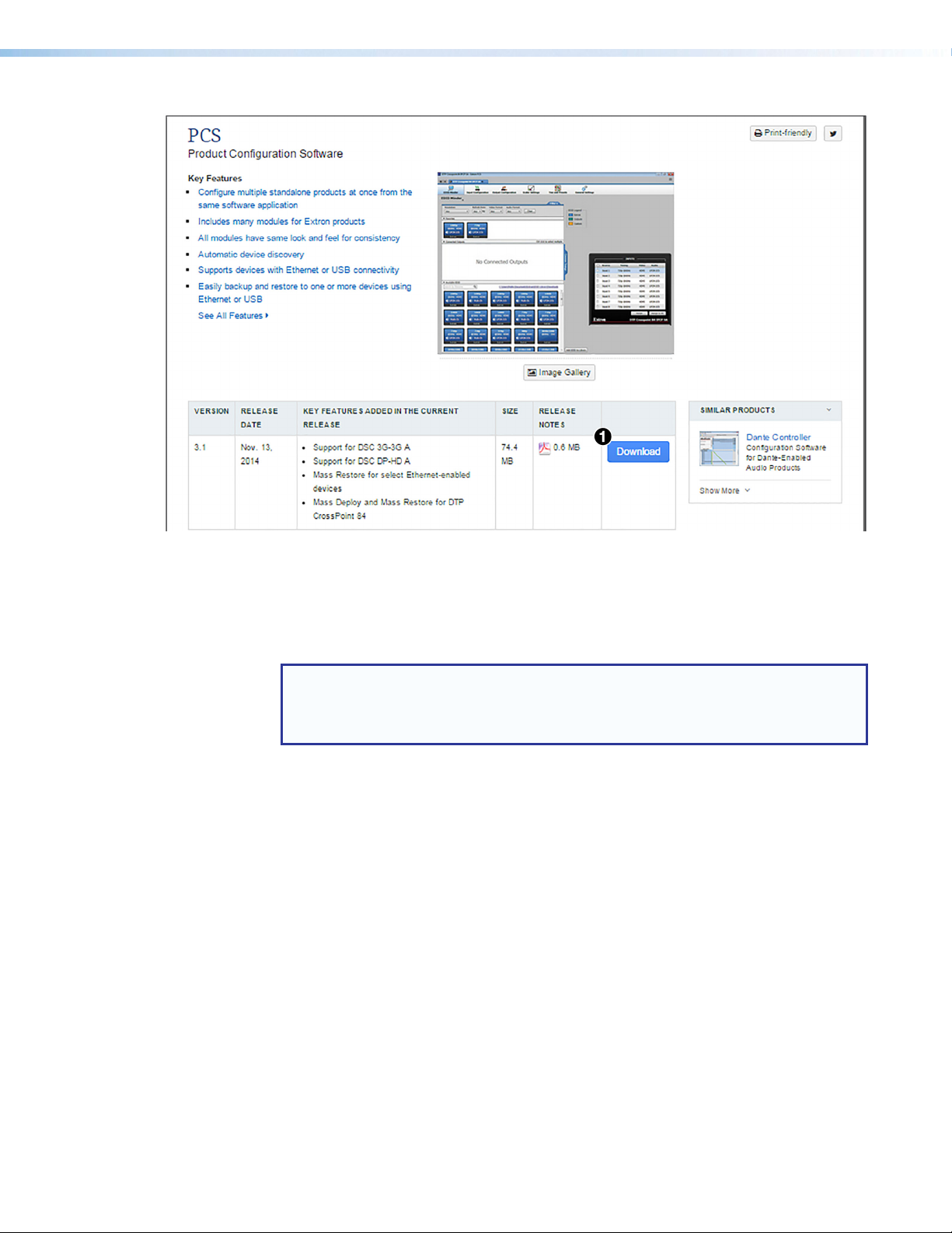
Fif
Figure 31. Download Now Button on the PCS Web Page
3. On the Download Center page that is displayed next, fill in the required information,
then click the Download pcss_vnxn.exe button.
4. If the File Download - Security Warning window appears, click Run to begin
downloading the installer file.
NOTE: To save the installation file to the computer hard drive to run later, click Save.
On the Save As window that opens, save the setup file to the desired location.
When ready to install the software, double-click on the pcss_vnxnxn.exe icon,
click Run on the Download screen that opens, and restart this procedure at step 6.
If, instead, a Download icon at the bottom of the page appears, wait until the icon
displays the name pcss_vnxnxn.exe, then click it.
5. On the next prompt window that opens, click Run to start the installation process.
6. Follow the instructions on the InstallShield Wizard screens to complete the
software program installation. By default the installation creates a folder called “Extron
PCS” in one of the following location on the computer (depending on Windows version):
c:\Program Files (x86)\Extron\Extron PCS or
c:\Program Files\Extron\Extron PCS
If there is not already an Extron folder in the computer Program Files or
Program Files (x86) folder, the installation program creates it.
MediaPort 200 • Product Configuration Software (PCS) 35
Page 43

Starting the PCS Software
1. To run the PCS configuration program, do either of the following:
• Double-click on the EAF.exe file, located on the computer at
c:\Program Files [or Program Files(x86)]\Extron\Extron PCS.
• Access the program from the Start menu on the computer as follows:
a. Click Start on the computer screen.
b. Select All Programs from the Start menu.
c. From the All Programs menu, select Extron Electronics.
d. From the Extron Electronics drop-down submenu, select the Extron
Product Configuration Software folder.
e. From the folder submenu, select Extron Product Configuration Software.
The Extron Product Configuration Software window opens.
2. On the PCS main window, locate the desired MediaPort in the Device Discovery
panel and click its name to select it (see figure 32 1 below).
TIP: If the MediaPort 200 does not have a user defined name (see General
Settings Tab on page 59 for information on naming the MediaPort), it can
be identified by type of connection (USB or TCP/IP) or by accessing the MAC
address, which is printed on the white label located on the back of the MediaPort.
The default name of the MediaPort in PCS ends with the unit’s MAC address.
Figure 32. PCS Software Window with MediaPort 200 Selected
3. Click the Connect button (see figure 32 2 above). The main window for the
MediaPort 200 opens.
If the MediaPort does not appear in the Device Discovery, click the TCP/IP button (see
figure 32 3 above). The TCP/IP login panel opens.
MediaPort 200 • Product Configuration Software (PCS) 36
Page 44

Figure 33. TCP/IP Login Panel
1. Enter the IP address where indicated (see figure 33 1 above) and the password, if one
is required. The default IP address is 192.168.254.254.
2. Click Connect (2). The MediaPort main window opens (see figure 34 below).
Figure 34. PCS Main Window for MediaPort 200
MediaPort 200 • Product Configuration Software (PCS) 37
Page 45

Updating Firmware via PCS
Firmware can be updated via PCS while the MediaPort is connected to the host PC with a
TCP/IP connection.
To download a firmware file:
1. Go to www.extron.com and click the Download tab (see figure 35 1).
2. From the Download page, select Firmware (2).
Figure 35. Extron Download Page
3. From the Download Center page, select M (figure 36 3 below) from the alphabetized
list at the top of the page.
4. Next, click Download (4) in the MediaPort 200 box.
Figure 36. MediaPort 200 Firmware Download Link
5. On the next page, provide the required information and click
Download MediaPort200_FW0x00x0000.exe.
6. Open the downloaded firmware installer and install the firmware file. The default install
location is Program Files (x86) > Extron > Firmware > MediaPort.
MediaPort 200 • Product Configuration Software (PCS) 38
Page 46

To update firmware via PCS:
1. Connect the MediaPort 200 to the host PC via the LAN port (see LAN Port on
page 21).
NOTE: Firmware updates are not possible via the front panel USB Config port.
2. From the PCS main window for MediaPort 200 (see figure 34 on page 37), select
the drop down triangle from the MediaPort 200 (see figure 37 1 below).
3. From the drop-down list, select Update Firmware (2) then Update Firmware to this
Device (
4. Click Continue.
Figure 37. Accessing Update Firmware
5. From the Update Firmware to This Device dialog box, click
Open Firmware File... (see figure 38
file (default location is Program Files (x86) > Extron > Firmware > MediaPort).
6. Select Open.
7. Select Update (5) to update the firmware. The front panel LCD on the MediaPort 200
reads Firmware Update Verify File with a completion percentage. Followed by
Firmware Update Installing with a completion percentage.
3
).
below) and browse the disk for the firmware
4
Figure 38. Update Firmware to This Device Dialog Box
The MediaPort front panel LCD reads Firmware Update Complete and reboots.
MediaPort 200 • Product Configuration Software (PCS) 39
Page 47
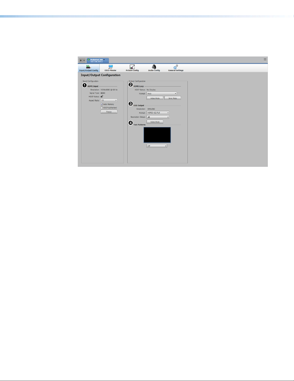
Input/Output Configuration Tab
The Input/Output Config tab provides status indicators and configuration for the
following video inputs and outputs:
HDMI Input on page 41
1
HDMI Loop on page 42
2
Figure 39. Input/Output Config Tab
USB Output on page 42
3
Test Patterns on page 43
4
MediaPort 200 • Product Configuration Software (PCS) 40
Page 48

HDMI Input
Figure 40. HDMI Input Panel
Resolution — This read only field displays the input resolution and refresh rate of the
1
HDMI input.
Signal Type — This read only field displays the type of signal coming into the HDMI
2
input.
HDCP Status — This read only field displays either a closed lock indicating HDCP
3
encrypted content coming through the input, or an open lock (pictured above) indicating
content that is not HDCP encrypted.
Aspect Ratio — This drop-down menu has two options:
4
• Fill — Takes the input signal and scales it to fill the output.
• Follow — Follows the aspect ratio of the input signal, maintaining the input’s native
aspect ratio with regard to the current USB output resolution.
Auto Memory — When checked (default), Auto Memory automatically saves Input
5
Config and Picture Control settings, which automatically recalls the next time the same
input is connected.
HDCP Authorized — If this box is left unchecked (default), sources are blocked from
6
encrypting their output, which may prevent some content from being displayed.
NOTE: If HDCP Authorized is enabled and an HDCP source is present, the encrypted
video can only pass to an HDCP compliant sink connected to the HDMI Loop
output, and is not passed to the USB output.
Freeze — Freezes the HDMI input.
7
MediaPort 200 • Product Configuration Software (PCS) 41
Page 49

HDMI Loop
USB Output
Figure 41. HDMI Loop Panel
HDCP Status — This view only field displays the HDCP capabilities of the display
1
connected to the HDMI Loop, if one is connected.
Format — This drop-down menu defines the video output format sent to the display
2
connected to the HDMI Loop. If left on Auto (default), MediaPort auto detects which
output format is best.
Video Mute — This button mutes the HDMI Loop output to black.
3
Sync Mute — This button mutes the sync signal to the HDMI Loop output as well as
4
the video signal.
Figure 42. USB Output Panel
Resolution — This view only field displays the resolution being sent by the USB
1
Output.
Format — This drop-down menu allows selection of USB video output format.
2
• MJPEG 422 Full (default) • MJPEG 420 Full
• MJPEG 422 Limited • MJPEG 420 Limited
Resolution Group — This drop-down menu allows selection of following USB
3
streaming resolution groups:
• All — All resolutions are available
(default).
• Medium — 640x360/16:9,
640x480/4:3
Video Mute — This button mutes video from the USB Output.
4
MediaPort 200 • Product Configuration Software (PCS) 42
• Low — 320x180/16:9, 320x240/4:3,
424x240/16:9, 640x360/16:9
• High — 640x360/16:9, 960x540/16:9,
1280/720/16:9,1920x1080/16:9
Page 50

Test Patterns
Figure 43. Test Patterns Panel
This panel offers several internal test patterns from a drop-down menu (see figure 43 1
above) to aid in the MediaPort configuration and setup purposes.
EDID Minder Tab
Extron EDID Minder is an EDID management tool that automatically manages the EDID
information between a digital display device and one or more input sources.
The EDID Minder tab allows you to assign EDID to an input, import non-factory default
EDID into the PCS software EDID library, and save the EDID from a connected
MediaPort 200 user-assigned memory slot or the EDID from a display connected to the
MediaPort HDMI Loop output. You can also view the resolution, refresh rate, and audio
support of all HDMI EDID configurations located locally in the PCS EDID library and remotely
on the connected MediaPort 200.
The following panels are available in the EDID Minder tab:
Filter on page 44
1
Favorites on page 44
2
Connected Outputs on page 44
3
Figure 44. EDID Minder Tab
MediaPort 200 • Product Configuration Software (PCS) 43
Available EDID on page 45
4
Input on page 45
5
Page 51

Filter
Favorites
Figure 45. Filter Panel
The Filter panel is a search tool that allows available EDID settings to be filtered according
to following parameters:
• Resolution • Video Format
• Refresh Rate • Audio Format
Figure 46. Favorites Panel
The Favorites panel contains a list of favorite EDID for quick selection without having to
search through all available EDID. EDID can be clicked and dragged from the
Available EDID panel into the Favorites panel to be added as a favorite. To remove a
favorite from the Favorites panel, right click the EDID being removed, and select
Remove from Favorites.
Connected Outputs
Figure 47. Connected Outputs Panel
The Connected Outputs panel displays the EDID of the sink device that is connected to the
HDMI Loop output.
MediaPort 200 • Product Configuration Software (PCS) 44
Page 52

Available EDID
Figure 48. Available EDID Panel
The Available EDID panel displays the library of available EDID configurations located on
the connected MediaPort 200 and the host PC.
Input
Figure 49. Input Panel
The Input panel displays the current EDID configuration of the source connected to the
HDMI input.
MediaPort 200 • Product Configuration Software (PCS) 45
Page 53

Picture Config Tab
The Picture Config tab displays signal sampling parameters, performs Auto-Image, sets
certain picture controls, saves and recalls user and input presets, and applies overscan.
The following panels are available on the Picture Config tab:
Adjust Graphically on page 47
1
Adjust Numerically on page 48
2
Picture Controls on page 49
3
Figure 50. Picture Config Tab
Signal Sampling and Overscan on
4
page 49
Input Presets on page 50
5
MediaPort 200 • Product Configuration Software (PCS) 46
Page 54

Adjust Graphically
Figure 51. Adjust Graphically Panel
Image Adjust Graphic — Allows for the resizing of the input signal. This panel gives
1
the user handles on the top, bottom, sides and corners to adjust the size of the image.
Lock Aspect Ratio — Marking this checkbox locks the aspect ratio of the image so
2
when adjustments are made on one side, the others are automatically adjusted to retain
original aspect ratio.
MediaPort 200 • Product Configuration Software (PCS) 47
Page 55

Adjust Numerically
Figure 52. Adjust Numerically Panel
Horizontal Position — Adjusts the horizontal position of the image with a minimum
1
value of -1920 and a maximum value of 1920. The default is 0 with adjustments made
in 8 pixel increments.
Horizontal Size — Adjusts the horizontal size of the image, with a minimum value of
2
120 and a maximum value of 4096. The default is 640 with adjustments made in 8 pixel
increments.
Vertical Position — Adjusts the vertical position of the image with a minimum value of
3
-1200 and a maximum value of 1200. The default is 0 with adjustments made in 2 pixel
increments.
Vertical Size — Adjusts the vertical size of the image, with a minimum value of 64
4
and a maximum value of 2400. The default is 360 with adjustments made in 2 pixel
increments.
Auto-Image — Performs an Auto-Image function.
5
Auto-Image & Fill — Performs an Auto-Image and fills the entire output raster.
6
Auto-Image & Follow — Performs an Auto-Image and compensates for the native
7
aspect ratio of the applied input.
MediaPort 200 • Product Configuration Software (PCS) 48
Page 56

Picture Controls
The Picture Controls panel adjusts the brightness and contrast of the input signal.
Figure 53. Picture Controls Panel
Brightness Slider — Adjusts the brightness of the input signal with a minimum value of
1
0 and a maximum value of 127. The default is 64.
Contrast Slider — Adjusts the contrast of the input signal with a minimum value of 0
2
and a maximum value of 127. The default is 64.
Signal Sampling and Overscan
The Signal Sampling panel displays the details of the applied HDMI input signal’s active
video area.
The Overscan drop-down menu lists the percentages by which the MediaPort zooms
and crops the SMPTE input resolutions to mask edge effects and ancillary data that are
common in broadcast signals.
Overscan is applied only to SMPTE input rates: 480i (NTSC), 576i (PAL), 480p, 576p, 720p,
1080i, or 1080p.
Figure 54. Signal Sampling and Overscan Panels
MediaPort 200 • Product Configuration Software (PCS) 49
Page 57

Input Presets
The Input Presets panel allows the user to create, name, and save user input presets, as
well as recall presets that have been saved previously. A preset saves certain parameters
of the current MediaPort video configuration. A saved preset can be recalled and applied to
the MediaPort. Presets save and recall the following parameters:
• Image Size • Brightness
• Image Position • Contrast
Figure 55. Input Presets Panel
Preset List — Up to 16 presets can be saved in the Input Presets panel, labeled P1
1
through P16. Empty preset slots appear with the name [UNASSIGNED].
Save Preset — Saves the current settings to the selected preset slot. If the selected
2
preset slot already has a preset saved to it, a dialog box apears with the option to
overwrite the existing preset.
Recall Preset — Recalls the selected preset and applies the parameters saved in the
3
preset.
Clear — Clears the selected preset slot, deleting the preset saved in that slot.
4
MediaPort 200 • Product Configuration Software (PCS) 50
Page 58

Audio Config Tab
The Audio Config tab contains all audio mixing and DSP for the MediaPort 200 within the
following sub-tabs:
This is a general overview of the audio controls. In-depth coverage of this application setup
can be found in Standalone MediaPort 200 Application Setup on page 83 or
MediaPort 200 with External DSP with AEC Application Setup on page 93
depending on your selected audio mode (see Setting Audio Modes on page 17).
Input Tab
The Input tab contains gain, attenuation, mute, and DSP settings for the MediaPort 200
audio inputs.
• Input Tab • Output Tab
• Mix Tab • Preset and Digital I/O Tab
USB Playback Panel
1
HDMI Panel
2
Line In Panel
3
Figure 56. Input Tab
USB Playback Panel — The USB Playback panel provides level and mute control
1
for program audio played from the computer, and communications audio from a
web-based soft codec. This panel contains faders for attenuation of the incoming USB
playback audio from the host PC. At the bottom of the panel there are text fields for
entering desired attenuation levels, individual left and right Mute buttons, a Gang button
which ties left and right channels together, and a Left/Right dBFS meter for monitoring
input signal level.
MediaPort 200 • Product Configuration Software (PCS) 51
USB Communications Panel
4
Mic/Line Panel
5
DSP Icon
6
Page 59

HDMI Panel — The HDMI panel provides level and mute control for audio coming
2
through the HDMI input from a camera with built-in microphone, or a signal from an
HDMI switcher that contains audio. This panel contains faders for providing up to 24dB
of gain or 18 dB of attenuation of the incoming HDMI audio from connected source.
At the bottom of the panel there are text fields for entering desired gain or attenuation
levels, individual left and right Mute buttons, a Gang button which ties left and right
channel controls together, and a Left/Right dBFS meter for monitoring input signal level.
NOTE:
• The HDMI audio input should not be used for microphone audio if a mic is
connected to the Mic/Line input.
• The panel is unavailable (grey) if there is no audio signal detected at the HDMI
input.
Line In Panel — The Line In panel provides level and mute control for program audio
3
coming from a source connected to the stereo Line input, such as an iPod or other
program source. This panel contains faders for providing up to 24 dB of gain or 18 dB
of attenuation to the incoming signal from the Line In input. At the bottom of the panel
there are text fields for entering desired gain or attenuation levels, individual left and right
mute buttons, a gang button that ties left and right channel controls together, and a
Left/Right dBFS meter for monitoring input signal level.
USB Communications Panel — The USB Communications panel provides level and
4
mute control for communications audio received from the far-end, delivered through
the standalone Unified Communication (UC) application being used, and is mixed
separately from the USB playback audio. At the bottom of the panel there are text fields
for entering desired attenuation levels, individual left and right Mute buttons, a Gang
button that ties left and right channel controls together, and a Left/Right dBFS meter for
monitoring input signal level.
Mic/Line Panel — The Mic/Line panel provides level and mute control for
5
microphone audio or microphone mix audio from an external DSP to be sent to the far
end. This panel contains a Phantom Power button, a fader for providing up to 60 dB of
gain and 18 dB of attenuation on the incoming signal. At the bottom of the panel there
is a text field for entering desired gain or attenuation levels, a channel Mute button, and
a mono dBFS meter for monitoring input signal level.
NOTE: Mic/Line is muted by default. Connect a microphone, apply phantom power
if needed, then unmute.
DSP Icon — Each input channel contains DSP that can be accessed by clicking the
6
DSP icon that opens the input DSP window. Within the DSP window, there are up to
three tabs:
• Filters • Compressor • Ducking
MediaPort 200 • Product Configuration Software (PCS) 52
Page 60

Input DSP Window
The DSP window can be accessed by clicking the DSP Icon (see figure 56 6 on
page 51), and opens to the Filters tab. Clicking the DSP Icon hides the Input
DSP window. Each input channel contains its own DSP. All channels contain filter and
compressor DSP, with the USB Communications and Mic/Line channels containing
ducking as well.
Filters
Figure 57. DSP Filter Tab
Filter Graphic — Visually represents the active and inactive filters from the filter list.
1
Also provides frequency, boost/cut, and Q control for filters via handles in the graph and
numbered sliders directly below the graph.
Filter List and Parameters— The Mic/Line input contains 5 slots for filters, while the
2
other line inputs contain 3. Each of the slots allows for any of the available filters to be
applied and adjusted. Duplicate filters are allowed in multiple slots. All parameters for
each filter can be adjusted in this list. In addition, clicking the square in the Active
column engages the selected filter. A blue square in the Active column represents an
active filter. Filters are inactive by default. Available filters include:
• High Pass • Treble (Shelving)
• Low Pass • Parametric
• Bass (Shelving)
Show Filter Selection and Parameters — When this button is engaged (blue), the
3
filter drop-down menus and available parameters are visible. When disengaged, the
filters and parameters are hidden. Filters and parameters are visible by default.
Copy and Paste — Allows a filter type and parameters to be copied and pasted from
4
one slot to another.
MediaPort 200 • Product Configuration Software (PCS) 53
Page 61

Compressor
Figure 58. DSP Compressor Tab
Compressor Graphic — Visually represents the compressor parameters and allows
1
for the adjustment of threshold and ratio by clicking and dragging the yellow-dot
handles.
Compressor Parameters — This panel contains the Bypass button (engaged by
2
default) as well as numerical fields for adjusting Threshold, Ratio, Attack Time,
and Release Time. Attack and Release Time can also be adjusted by clicking and
dragging the sliders next to the text fields.
Reset to Default — Resets all compressor parameters to default.
3
MediaPort 200 • Product Configuration Software (PCS) 54
Page 62

Ducking
Figure 59. DSP Ducking Tab
Ducking Parameters — Text fields are available for adjusting Threshold, Hold Time,
1
and Release Time. Defaults are shown in figure 59 above.
Duck and Duck By — In the Duck column, select which channels should be ducked
2
when signal above the threshold is present. In the Duck By column, enter the amount
each channel should be ducked in dB.
NOTE: Only Mic/Line and USB communications inputs can trigger ducking, therefore
ducking controls are only available on those channels.
MediaPort 200 • Product Configuration Software (PCS) 55
Page 63

Mix Tab
Program Mix Panel
1
From Far End Panel
2
Near End Panel
3
Figure 60. Mix Tab
Program Mix Panel — Contains level and mute control for USB Playback, HDMI, and
1
Line In audio signal for up to 100 dB of attenuation or up to 12 dB of gain to be sent
to local sound reinforcement and the far end. Faders or text fields can be used to set
proper mix level. Mute buttons are also available for each channel. The mix created in
this panel is then sent to the Near End panel as well as to the Program fader of the Mix
to Far End panel.
From Far End Panel — Contains level and mute control for the USBCommunications
2
signal from the far end for up to 100 dB of attenuation or up to 12 dB of gain to be sent
to local sound reinforcement. The fader or text field can be used to set proper mix level.
A Mute button is available for the channel.
Near End Panel— Contains controls to attenuate or mute the near end room volume
3
which acts as a master attenuation for USB Playback, HDMI, Line In and USB
Communications (if Mix USB Communications is selected) signals before being sent
to the Output tab. The fader or text field can be used to set desired attenuation. A Mute
button is available for the channel. Line output signal can be configured as stereo or
dual mono.
Mix to Far End Panel — The Mic fader provides attenuation and mute control for
4
the microphone audio being sent to the far end while the Program fader provides
attenuation and mute control for the mix of USB Playback, HDMI, and Line In
audio being sent to the far end. The faders or text fields can be used to set desired
attenuation. A Mute button is available for both channels. This audio can be configured
as stereo or dual mono.
Mix USB Communications Checkbox —When this box is checked (default), USB
5
communications audio is routed to the rear panel analog Line output and Ref output. If
unchecked, USB communications is only routed to the Ref output.
NOTE: If using an external DSP with AEC, this box should be unchecked so that USB
communications audio is only sent to the Ref output.
Mix to Far End Panel
4
Mix USB Communications Checkbox
5
Mix USB Playback Checkbox
6
MediaPort 200 • Product Configuration Software (PCS) 56
Page 64
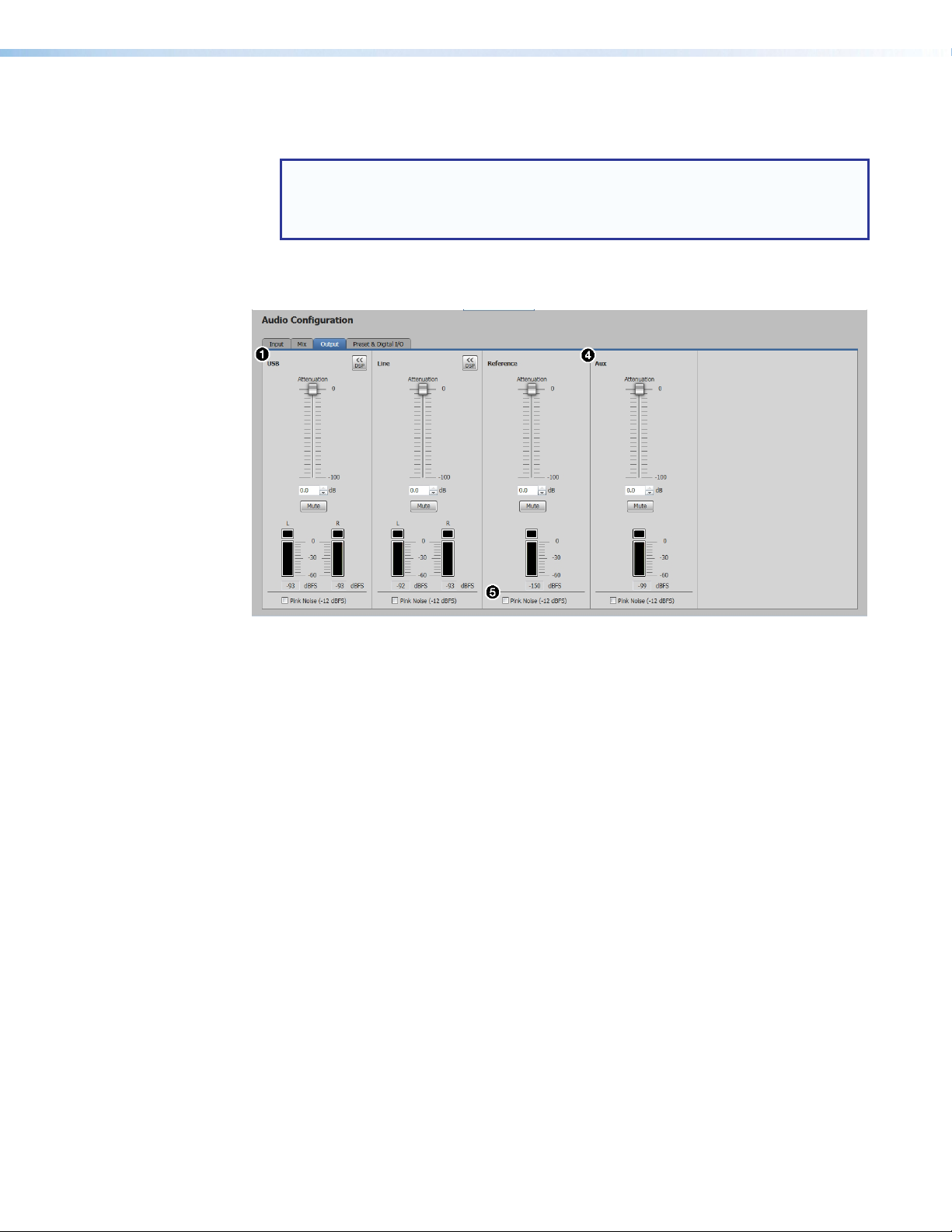
Output Tab
Mix USB Playback Checkbox — When this box is checked (default), USB Playback
6
audio is routed into the mix sent to the far end via the USB output.
NOTE: If using a Web-based soft codec, it may be necessary to uncheck this box,
essentially muting USB playback audio to the far end. Web-based codec audio is
sometimes recognized as playback audio instead of communications audio, and
then creates a feedback loop if sent to the far end.
Figure 61. Output Tab
USB — The USB panel provides attenuation and mute control for all audio being sent
1
through the USB output, which includes: USB Playback, HDMI, Line In, and Mic/Line
audio. The USB panel also contains output filter and limiter DSP which can be accessed
by selecting the DSP Icon. Output DSP functions similar to the DSP on the input
channels (see Input DSP Window on page 53).
Line — The Line panel provides attenuation and mute control for all audio being
2
sent through the Line output, which includes: USB Playback, HDMI, Line In, and USB
Comm audio (if selected in the From Far End panel of the Mix tab). The Line panel
also contains output filter and limiter DSP which can be accessed by selecting the DSP
Icon. Output DSP functions similar to the DSP on the input channels (see Input DSP
Window on page 53).
Reference — The Reference panel provides attenuation and mute control for far end
3
communications audio being sent to the AEC Ref output to an external DSP with AEC.
Aux — The Aux panel provides attenuation and mute control for Mic/Line audio being
4
sent to the Aux output for local speech reinforcement or to a hardware video codec.
Pink Noise Generator — Each output channel contains a checkbox that activates
5
a Pink Noise generator that outputs pink noise at a level of -12 dBFS. The signal is
generated at the output stage, pre-processing. Only output DSP is applied to the pink
noise signal.
MediaPort 200 • Product Configuration Software (PCS) 57
Page 65

Preset and Digital I/O Tab
Figure 62. Preset and Digital I/O Tab
Audio Preset List — Displays the saved presets available for recall and empty preset
1
slots available to save new presets. Empty preset slots appear as [unassigned]. There
are 16 preset slots available.
Save/Recall Preset and Clear — The Save Preset button saves the current audio
2
configurations and DSP settings as a recallable preset to the empty selected preset
slot. The Recall Preset button applies the configurations saved to the selected
preset. The Clear button removes a saved preset and returns the preset slot to
[unassigned].
Configure Digital I/O — Contains the available actions for each digital input and
3
output. Clicking each drop-down menu provides the actions and states available for
each input and output. For more information on configuring digital I/O ports, see the
MediaPort 200 Help file.
MediaPort 200 • Product Configuration Software (PCS) 58
Page 66

General Settings Tab
Hardware Settings
1
HDCP Notification
2
HDCP Mode for HDMI Loop
3
Audio Mode
4
Figure 63. General Settings Tab
Hardware Settings — Provides the following information and configuration options
1
(see MediaPort 200 Help for more information):
• Unit Information — Displays device specific information such as firmware version,
temperature, device name, DHCP status, IP address, and MAC address.
• Device Name — Contains a text field for renaming the selected MediaPort 200.
Only letters, numbers, and hyphens are available for device names.
NOTE: The Device Name also doubles as the TCP/IP hostname.
• USB Name — Contains a text field for assigning a new MediaPort 200 USB device
name recognized by Windows (default is Extron MediaPort 200).
• Date and Time — Displays date, time, and time zone information. All information
can be set manually or parameters can be synced to the host PC.
• Password — Contains fields for setting administrator and user passwords.
HDCP Notification — Contains radio buttons that determine the color (green or black)
2
of the output signal when sending HDCP encrypted content to a non-HDCP compliant
display.
HDCP Mode for HDMI Loop — Contains radio buttons for selecting the HDCP
3
encryption of the HDMI Loop output (see MediaPort 200 Help for more information).
Executive Mode
5
No Signal Indication Mode for USB
6
Output
Manage OSD Image
7
MediaPort 200 • Product Configuration Software (PCS) 59
Page 67

Audio Mode — Contains radio buttons for selecting Standalone or External DSP
4
with AEC audio modes (see Setting Audio Modes on page 17 ).
• Select Standalone (no external AEC) if there is no external DSP with AEC
attached to the MediaPort 200. This causes Windows to enumerate the MediaPort
as a Speakerphone and the host Unified Communications (UC) application to
provide AEC.
• Select External DSP with AEC if there is an external DSP with AEC attached to
the MediaPort 200. This causes Windows to enumerate the MediaPort as an Echo
Cancelling Speakerphone and the external DSP provides AEC.
NOTES:
• The MediaPort restarts after changing the audio mode. The message
Rebooting...Please Wait appears on the MediaPort front panel LCD
and PCS displays a dialog box saying the connection to the MediaPort has
been lost and ask if it should attempt to reconnect. Select Cancel to return
to the Device Discovery menu.
• After changing the audio mode of the MediaPort, Windows recognizes it as
a different device, requiring Windows to be reconfigured with the MediaPort
in its new audio mode (see Configuring Windows for MediaPort 200 on
page 27).
Executive Mode — Contains radio buttons for two executive modes, unlocked and
5
locked (see Front Panel Lockout (Executive Mode) on page 80).
No Signal Indication Mode for USB Output — Contains radio buttons for selecting
6
the default screen displayed when no input signal is detected (see No Signal Indicator
(USB Output) on page 82).
Manage OSD Images — Contains a dialog box for uploading a custom OSD image to
7
be displayed when no USB output signal is detected.
MediaPort 200 • Product Configuration Software (PCS) 60
Page 68

Front Panel
ADJ
US
EE
GG
FF
Operation
This section discusses the functions available through the front panel to configure and
operate the MediaPort 200. The following topics are discussed:
• Front Panel Features
• Powering On
• Menus on the LCD Screen
• Front Panel Lockout (Executive Mode)
• Resetting
• No Signal Indicator (USB Output)
• Video Presets
Front Panel Features
Figure 64 below shows the front panel features of the MediaPort:
BB CC
USB
HOST
VIDEO SEND
AUDIO SEND
AUDIO RETURN
CONFIG
AA
HDMI
SIGNAL IN
HDCP IN
LOOP OUT
LOOP HDCP
HDMI LEDs E Adjust Knobs
A
USB LEDs F Next Button
B
LCD Screen G USB Config Port
C
Menu Button
D
Figure 64. MediaPort 200 Front Panel
DD
MENU
NEXT
MediaPort 200
ADJUST
MediaPort 200 • Front Panel Operation 61
Page 69

HDMI LEDs — When the unit is powered on and any of the following conditions are
A
true, one or more of these four green LEDs lights to indicate the type of input signal that
is present.
• Signal In — An active HDMI input signal is present.
• HDCP In — An HDCP encrypted input signal is being received.
• Loop Out — A sink is detected from the HDMI loop out connector.
• Loop HDCP — The signal coming out of the HDMI loop out is HDCP encrypted.
USB LEDs — These four green LEDs light to indicate the connection and signal status
B
of the rear panel USB port.
• Host — The rear panel USB port is connected to and enumerated with the host
computer.
NOTE: The Host LED blinks when the MediaPort is connected to a device
running Chrome OS and the connection has been put to sleep due to
inactivity. Once activity resumes, the Host light lights steadily.
• Video Send — A video signal is being output to the host via USB.
• Audio Send — An audio signal is being output to the host via USB.
• Audio Return — Audio input is being received from the host via USB.
LCD Screen — This LCD window displays menus, messages, and selections from
C
menus and submenus (see Menus on the LCD Screen on the next page for more
information).
Menu Button — Press this button to access the MediaPort menu system and step
D
through the menus displayed on the LCD screen (C) (see Menus on the LCD Screen
on the next page).
Adjust Knobs — Rotate these horizontal ([) and vertical ({) Adjust rotary encoders
E
to scroll through submenu options and make adjustments to selections.
Next Button — Press this button to step through the submenus displayed on the LCD
F
screen when a menu is selected.
USB Config Port — Connect a computer to this USB mini B port for device
G
configuration.
Powering On
Default Cycle
Apply power by connecting the provided IEC power cord to the MediaPort rear panel power
connector (see figure 11 A on page 19). Connect the MediaPort to an AC power
source.
When power is applied, the LCD screen lights and remains blank for approximately
30 seconds, after which Extron MediaPort 200 is displayed. After approximately
70 seconds, the unit part number and firmware version are displayed briefly (approximately
2 seconds). After these initial screens, the default cycle begins, in which the LCD screen
rotates every 2 seconds through four screens: the input video signal type and rate, the USB
video output rate, the USB audio input status, and the USB output signal status. The default
cycle continues while the menu system is not in use.
MediaPort 200 • Front Panel Operation 62
Page 70

Figure 65 below shows the order in which the screens appear at power-up and during the
default cycle.
Power
On
30 sec.
Extron
MediaPort 200
70 sec.
60-1488-01
FW v1.00
2 sec.
Figure 65. Power-up and Default Cycle Screens Example
Menus on the LCD Screen
The MediaPort 200 menus that are displayed on the LCD screen enable configuration and
operation of the product without the PCS software or SIS commands. The menu navigation
buttons (Menu and Next) are located to the right of the LCD screen. Press these buttons
to cycle through the available menus and submenus, and use the horizontal and vertical
Adjust knobs to select items.
Menu System Overview
The menu system consists of eight menus, each of which have submenus that enable
desired adjustments to be made (see the Menu Flow Diagram on the next page).
Video In: HDMI
1280x720@60Hz
USB Audio Send
No Signal
USB Video Send
2 sec.
USB Audio Return
2 sec.
None
None
Using the Menus
1. To access the menu system, press the Menu button on the front panel. The first menu
(Quick Setup) is displayed on the LCD screen.
2. Select other menus by repeatedly pressing the Menu button until the desired menu is
displayed.
MediaPort 200 • Front Panel Operation 63
Page 71

3. Press the Next button on the front panel repeatedly to cycle through the submenus
within the selected menu.
4. When the desired submenu is displayed,
rotate the horizontal ([) or vertical ({) Adjust
knob clockwise or counterclockwise to cycle
through the submenu options. To return to a
Default
Cycle
menu from within one of its submenus, press
Menu.
5. When the Adjust knob has been rotated to
Menu
display the desired value, do one of the
following to confirm a selection:
• Press Next to display another submenu.
• Press the Menu button to exit the
submenu.
• Wait until the LCD screen times out
to the default cycle (approximately
30 seconds).
Quick
Setup
Menu
Input
Presets
30 sec.
30 sec.
NOTES:
Menu
• The default items on the LCD
menus are usually followed by an
asterisk on the LCD screen.
• The menus time out and the
Picture
Control
Menu
30 sec.
default cycle is displayed after
30 seconds of inactivity. However,
any selections made with the
Adjust knobs are saved and
remain in effect until they are
Input
Configuration
Menu
30 sec.
changed or the unit is reset to
factory defaults (see Resetting on
page 80).
Output
Configuration
Menu
30 sec.
Menu Flow Diagram
The flow diagram at right shows the menus that
are displayed on the front panel LCD screen and
the order in which they appear when the Menu
button is pressed repeatedly.
Audio
Configuration
Menu
Advanced
Configuration
30 sec.
30 sec.
Menu
Menu
View Comm
Settings
Menu
Exit Menu?
Press NEXT
Next
30 sec.
30 sec.
MediaPort 200 • Front Panel Operation 64
Page 72

Quick Setup Menu
Figure 66 below contains a selection of items that are also available on other menus. It
allows several basic configuration adjustments to be made to the MediaPort.
Default
Cycle
Menu
Quick
Setup
Next
Auto-Image
<No>
Next
Activate Auto-Image.
• No
• Yes
Test Pattern
Off
Select a video test pattern.
• Off (Default) • Crosshatch
• Crop • Color Bars
• Alt Pixels • Grayscale
Figure 66. Quick Setup Menu
Rotate either
knob to select a setting.
Next
Next
Adjust
HDMI Input EDID
720p@60Hz
Assign an EDID to the HDMI input.
See the Resolution and Refresh Rate
•
table on page 35 for a complete list
of available resolutions.
• Default: 720p @ 60 Hz
Aspect Ratio
Fill
Select the amount of the display
the image will fill.
• Fill (Default)
• Follow
Next
Next
From this menu, the following can be configured:
• Auto-Image — Performs a one-time Auto-Image on the video input (see Performing
Auto-Image on the next page for more information about this function). Rotate either
Adjust knob to select Yes or No.
• HDMI Input EDID — Select the Extended Display Identification Data (EDID) for the
input, or match it to the output rate (see Input EDID Table on page 72 for EDID
data). The default is 720P @ 60 Hz.
• Aspect Ratio — Specify aspect ratio handling of the HDMI input. Rotate either encoder
to select Fill (fills the entire screen) or Follow (displays with the aspect ratio of the
input).
• Test Pattern — Choose a test pattern to aid in setting up the MediaPort. Rotate either
encoder to select one of the available patterns: Off (no test pattern), Crop, Alt Pixels,
Crosshatch, Color Bars, and Grayscale.
NOTE: On the LCD screen, a default value is indicated by an asterisk (*) next to it.
MediaPort 200 • Front Panel Operation 65
Page 73

Performing Auto-Image
When Auto-Image is performed, the MediaPort 200 attempts to size and position the image
to fill the display screen (Fill mode) or to use the native aspect ratio of the input (Follow
mode). A one-time Auto-Image can be performed on the current input using SIS commands
or the LCD menus.
Only the horizontal and vertical positioning and the horizontal and vertical size are adjusted
by the Auto-Image. All other controls are left unchanged.
• If the aspect ratio has been set to Fill, the H and V position returns to 0,0, and the H
and V Size is set to match the current output rate.
• If the aspect ratio has been set to Follow, the H and V position and size are set to
maintain the native aspect ratio of the input rate with respect to the current output
resolution.
Auto-Image is also useful for centering and sizing an image that has been adjusted out of
default settings.
Auto-Image can be performed by the following methods:
• LCD Menus
1. Press the front panel Menu button on the front panel once to display the Quick
Setup menu.
2. Press the Next button once to display Auto-Image.
3. Rotate either Adjust knob to select <Yes>.
4. Press Next. The LCD screen displays Press Next to Start Auto-Image.
5. Press Next again. When the Auto-Image process is finished, the LCD screen
displays Auto-Image Complete.
After approximately 2 seconds, the screen displays the next menu (HDMI Input
EDID). After another 30 seconds, the default cycle is displayed.
• SIS commands — Enter A, using a communication tool such as Extron DataViewer
(see Auto-Image on page 122 for more information).
Input Presets Menu
Input (user image) presets save the video settings for the current input. Each input has 16
available user image presets which can save settings or recall using this menu or an SIS
command (see Input Preset Name on page 126). The following settings are saved in a
user image preset:
• Preset name • Vertical position
• Contrast • Horizontal size
• Brightness • Vertical size
• Horizontal position
Saved user image presets can be recalled to be applied to the current input.
MediaPort 200 • Front Panel Operation 66
Page 74

Figure 67 below provides an overview of the Input Presets menu and submenus.
Quick
Setup
Menu
Input
Presets
Next
Recall Preset
<N/A>
Select an input preset.
• N/A (Default)
• Range: 1-16
Rotate either Adjust
knob to select a setting.
Next
Save Preset
<Unassigned>
Save the current input
settings to a preset.
• Unassigned (Default)
• Range: 1-16
Next
Figure 67. Input Presets Menu
Saving or Recalling an Input Preset
1. Press the Menu button on the front panel until Input Presets is displayed in the LCD
window.
2. Press the Next button until the desired submenu name is displayed: Recall Preset or
Save Preset.
3. Rotate either Adjust knob until the LCD screen displays the desired number of the user
image preset to save the current settings to, or to be recalled.
4. Press Next to save or recall the preset. When the operation is completed, the Input
Presets menu reappears.
To exit the input presets function without saving a preset, press Menu.
NOTES:
• The user image preset name can be assigned only using SIS commands
(see Input Preset Name on page 126) or the PCS control software (see the
MediaPort 200 Help file).
• User image presets can be saved at one input resolution and rate and recalled
to a different one.
Example: If the current output resolution is 640x480 and a 720p input is
applied, size and center a “letterbox” image for a 16:9 input resolution and save
it to an user image preset. Subsequently, if a 1080p resolution is applied to the
unit, the letterbox preset that was saved at 720p can be recalled with the new
1080p input resolution.
MediaPort 200 • Front Panel Operation 67
Page 75

Picture Control Menu
Adjusting the image size and position alters the image within the output raster. Image
adjustments are relative to the top left corner of the output raster.
The Picture Control menu positions an image (up to 1920x1080) within a virtual pixel
space with a horizontal range of -1920 to 1920, and a vertical range of -1080 to 1080. This
allows positioning of the image so that a portion of it is displayed within the constraints of
the output raster (output resolution), or off the screen entirely.
NOTES:
• The available range of the image position depends on the horizontal and vertical
USB output resolution. The image can be shifted off screen only by the amount of
the horizontal and vertical streaming resolution.
• Size and position values must be divisible by 8 (horizontal) or 2 (vertical).
Figure 68 below shows the line and pixel coordinates at which the image can be positioned.
In this chart:
x = Horizontal streaming resolution
y = Vertical streaming resolution
(-x, -y) (0, -y) (x, -y)
Virtual Pixel Space
(-x, 0) (0, 0)
The video within
this center section
is viewable on the
output.
(-x, y) (0, y) (x, y)
(x, 0)
Figure 68. Image Positioning Space
When the aspect ratio changes, the horizontal size and position values are updated
accordingly.
MediaPort 200 • Front Panel Operation 68
Page 76
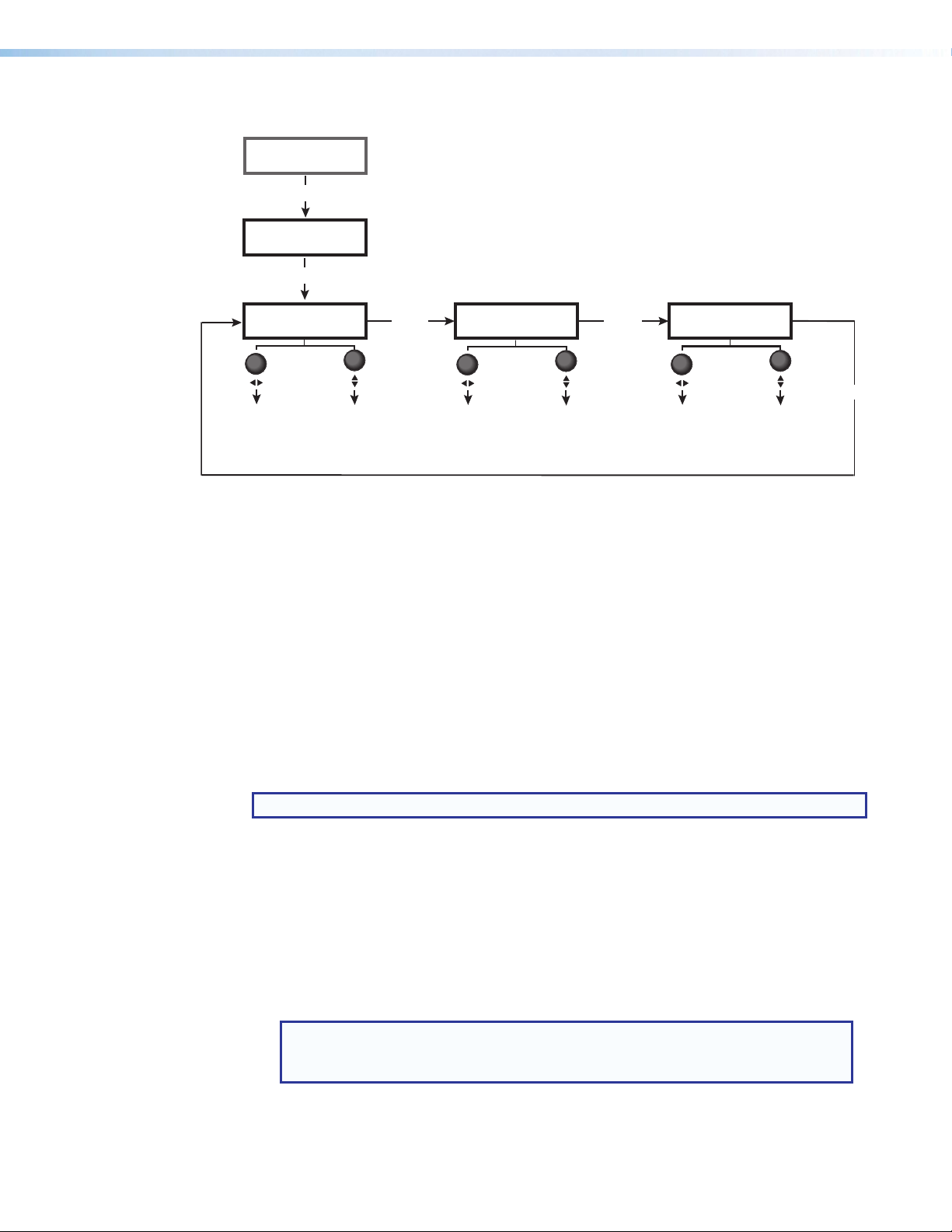
Figure 69 below provides an overview of the Picture Controls menu and its selections.
Input
Presets
Menu
Picture
Control
Next
H Position V
+0000 +0000
Position image relative to display center. Enlarge or shrink the image.
Horizontal
• Default: 0000
• Range: ± horizontal and
vertical streaming
resolution
Vertical
• Default: 0000
• Range: ± horizontal and
vertical streaming
resolution
Rotate the left Adjust knob to select horizontal
size and position or to set brightness.
Rotate the right Adjust knob to select vertical
size and position or to set contrast.
Next
H Size V
+1600 +0800
Horizontal
• Default: 1600
• Range: 0120 – 4096
Vertical
• Default: 0800
• Range: 0064 – 2400
Next
Bright Contrast
0064 0064
Increase or decrease range of image
black, light, and dark values.
Brightness
• Default: 0064
• Range: 000-127
Contrast
• Default: 0064
• Range: 000-127
Next
Figure 69. Picture Control Menu
The following selections are available:
• Horizontal Position — Specify whether the image should display off the screen
and to the left or the right (the amount of pixels depends on the horizontal streaming
resolution). The default is 0000 (the image is not off-screen).
• Vertical Position — Specify whether the image should display off the screen and
to the top or the bottom (the amount of pixels depends on the vertical streaming
resolution). The default is 0000 (the image is not off-screen).
• Horizontal Size — Specify the image width in pixels.
• Vertical Size — Specify the image height in lines.
• Brightness — Specify the black level of the input. The default is 064.
• Contrast — Increase or decrease the range of image light and dark values. The default
is 064.
NOTE: On the LCD screen, a default value is indicated by an asterisk (*) next to it.
Adjusting the Picture Controls
To adjust the picture controls for the current input:
1. Press the Menu button on the front panel repeatedly until the LCD screen displays
Picture Control.
2. Press the Next button until the setting to be changed is displayed.
3. Rotate the horizontal ([) Adjust knob to select the H or Bright value and the vertical
({) Adjust knob to select the V or Contrast value.
NOTE: As the encoder is rotated, horizontal size and position values are adjusted
in increments and decrements of 8 pixels. Vertical size and position values are
incremented or decremented by 2 lines.
4. Repeat steps 1 through 3 for each additional image adjustment.
MediaPort 200 • Front Panel Operation 69
Page 77

Input Configuration Menu
The Input Configuration menu enables adjustments to the input signal. Rotate the
horizontal and vertical Adjust knobs to set the values for the current selection. Figure 70
below shows the selections available from this menu.
Picture
Control
Menu
Input
Configuration
Next
HDMI Input EDID
720p@60Hz
Next
Select an EDID for the HDMI input.
• Default: 720p@60Hz
• See the Input EDID table on
page 73 for available EDIDs.
Tu rn either
to select a setting.
HDCP Authorized
Disabled
Enable or disable HDCP authorization.
• Enabled
• Disabled (Default)
Adjust
knob
Next
H Active V
1024 0768
View the active lines and pixels for the input.
Active Pixels (H)
Active Lines (V)
Next
Next
Auto Memory
On
Enable or disable Auto Memory.
• On (Default)
• Off
Aspect Ratio
Specify how much of the
display the image will fill.
• Fill (Default)
• Follow
Fill
Next
Figure 70. Input Configuration Menu
The following items are available on the Input Configuration menu:
• HDMI Input EDID — Select an EDID (resolution and refresh rate) emulation for the
HDMI input (see the Input EDID Table on page 72 for a list of the available EDIDs).
Rotate the left Adjust knob to select the resolution and the right knob to select the
refresh rate. The default is 720p @ 60 Hz.
NOTE: All factory-provided EDIDs are in HDMI, LPCM-2ch format. If DVI format is
required, use a custom EDID.
• Active Pixels and Lines — (Read only) View the amount of lines and pixels that
constitute the active area of the image for the current HDMI input. On the LCD screen,
active pixels are displayed under H and active lines under V.
• Aspect Ratio — Specify aspect ratio handling of the HDMI input. Rotate either Adjust
knob to select Fill (fills the entire screen) or Follow (displays with the aspect ratio of
the input). The default is Fill.
• In fill mode, to set an aspect ratio adjustment for a single input rate, select the
correct size and position manually from the Picture Controls menu (Size and
Position screens) (see Picture Control Menu on page 68).
MediaPort 200 • Front Panel Operation 70
Page 78

• In follow mode, each input rate is displayed with its native aspect ratio (4:3, 5:4,
15:9, 16:9, 16:10) with the correct letterbox or pillar box settings, visible in the Size
and Position screens of the Picture Controls menu.
For specific input or image raster to fill the screen in follow mode, manually set the
Position item on the Picture Controls menu to 0,0 and set the Size to match
the current output rate X,Y.
NOTE: In follow mode, the MediaPort calculates the aspect ratio at the point
the signal is applied. If the image size or position is changed via the Picture
Control menu, the aspect ratio of the image may no longer match the native
aspect ratio of the input signal. To resize and re-center the image, perform an
Auto-Image (see Performing Auto-Image on page 66).
• Auto Memory — Enables and disables Auto Memory. Auto Memories store the details
of an input signal in scaling bridge memory, so that the unit applies the appropriate
settings when it detects that signal again (see Auto Memories on page 82). Rotate
either Adjust knob to set Auto Memory to On (the default) and Off.
• HDCP Authorized — Disable HDCP communication by causing the MediaPort
HDMI input to report to a source device as a non-authorized HDCP sink (see HDCP
Authorized on the next page). Rotate either Adjust knob to select Enabled or
Disabled. The default is Disabled.
Selecting an input EDID
To select a resolution and rate for input emulation:
1. Select HDMI Input EDID from the Input Configuration menu.
2. Rotate the left Adjust knob to select the resolution and the right knob to select the
refresh rate.
3. Press Next or wait until the LCD screen times out to the default cycle (approximately
30 seconds). The selection is saved and appears next time the HDMI Input EDID
screen is accessed.
MediaPort 200 • Front Panel Operation 71
Page 79

Input EDID Table
Resolution 23.98 Hz 24 Hz 25 Hz 29.27 Hz 30 Hz 50 Hz 59.94 Hz 60 Hz
640x480 X
800x600 X
1024x768 X
1280x768 X
1280x800 X
1280x1024 X
1360x768 X
1366x768 X
1440x900 X
1400x1050 X
1600x900 X
1680x1050 X
1600x1200 X
1920x1200 X
480p X X
576p X
720p X X X X X X X X
1080i X X X
1080p X X X X X X X X
2048x1080 X X X X X X X X
Custom EDIDs
Add custom EDIDs or save the EDID of the HDMI loop output using SIS commands (see the
HDMI Input EDID on page 122) or the PCS control software (see the MediaPort 200 Help
file). These custom EDIDs are then added to the LCD menu.
HDCP Authorized
The MediaPort 200 accepts HDCP compliant signals and outputs them through the HDMI
loop out connection only.
NOTE: The USB output cannot display HDCP encrypted material under any
circumstances. It displays a green or black (user-selectable) screen when an HDCP
encrypted signal is detected.
The HDCP Authorized function can disable HDCP communication by causing the MediaPort
input to report to a source device as a non-authorized HDCP sink (display). This is useful
with devices such as Mac computers, iPhones, iPads, and some Windows 7 sources that
always encrypt their output if the downstream sink is HDCP-capable. If HDCP signals are
not allowed on an input, most content from these types of sources can be passed as a
non-encrypted signal to the USB output.
By disabling HDCP Authorized on the MediaPort HDMI input, the source does not encrypt
its output and non-HDCP protected content can be viewed from the MediaPort video USB
output.
MediaPort 200 • Front Panel Operation 72
Page 80

If HDCP Authorized is disabled and HDCP protected content is selected for the source, the
HDMI RGB 444 Full to an HDMI sink.
source either mutes its video output to black or displays a warning message.
HDCP Authorized can also be adjusted using via the PCS control software (see the
MediaPort200 Help file) or SIS commands (see HDCP Authorized — Input Reporting as
an HDCP Authorized Device on page 123).
Output Configuration Menu
The Output Configuration menu shows the current USB audio and video streaming
resolution and rate, configures the HDMI loop output, and enables or disables the HDCP
notification. Figure 71 below gives an overview of this menu.
Input
Configuration
Menu
Output
Configuration
Next
Next
USB Format
MJPEG 422 Full
Select the USB output
streaming format.
• MJPEG 422 Full (Default)
• MJPEG 422 Limited
• MJPEG 420 Full
• MJPEG 420 Limited
HDCP Note
On
Display or hide the green
HDCP notification screen.
• On (Default)
• Out
Next
Next
Resolution Group
All
Select the USB output
streaming resolution group.
• All (Default)
• Low
• Medium
• High
HDMI Loop Format
Auto
Select the HDMI loop output
format.
• Auto (Default)*
• DVI RGB 444
• RGB 444 Full
• RGB 444 Limited
• YUV 444 Full
• YUV 444 Limited
• YUV 422 Full
• YUV 422 Limited
*Auto outputs DVI to a DVI sink and
Next
Figure 71. Output Configuration Menu
• USB Format — Select the USB video output streaming format. Rotate either Adjust
knob to select between the following formats:
• MJPEG 422 Full (default)
• MJPEG 420 Full
• MJPEG 422 Limited • MJPEG 420 Limited
MediaPort 200 • Front Panel Operation 73
Page 81

• Resolution Groups — Select the resolution streaming group for the USB output from
the following groups:
• All (default) • Low — 320x180 (16:9), 320x240 (4:3),
424x240 (16:9), and 640x360 (16:9)
• Medium — 640x360 (16:9), 640x480
(4:3)
• High — 640x360 (16:9),
960x540 (16:9), 1280x720 (16:9), and
1920x1080 (16:9)
• HDMI Loop Format — Select the digital format of the HDMI loop output. HDMI, DVI,
or YUV video formats can be selected. Any DVI or HDMI video format can be discretely
forced.
NOTES:
• DVI — HDMI input signals are converted to DVI output format: RGB 444 full
8-bit, no audio, no InfoFrames.
• HDMI — HDMI input signals are converted to the set HDMI output format.
This includes the correct AVI InfoFrame data for the current video output
(colorspace, quantization, and so on). Audio signals and audio InfoFrame pass
through unaltered.
• The default setting, Auto, parses the EDID of the connected device and sets
the correct digital format. The Auto setting outputs DVI to a DVI sink and
HDMI RGB 444 Full to any HDMI sink.
• HDCP Note — Provides a means of determining if HDCP content restrictions are
preventing a video signal from passing. Because the USB output cannot display HDCP
encrypted content, the MediaPort notifies if protected content is detected on the input.
The display shows either of the following:
• If HDCP Note is Enabled: A green screen with HDCP Content in a text box is
displayed on the output when the connected device is not HDCP compliant and an
HDCP input is selected.
NOTES:
• The HDCP Content message appears only on a USB output. The HDMI
loop output displays only a green screen.
• The HDCP Content message does not appear if test patterns are enabled.
• The green screen can be displayed only when Enabled is selected for
HDCP Authorized.
• If HDCP Note is disabled: The output mutes to black when the connected device
is not HDCP compliant and an HDCP authorized input with protected content is
selected.
Audio Configuration Menu
The Audio Configuration menu enables audio that is processed through the
MediaPort200 to be adjusted. The volume level of the microphone and program audio
that is sent to the far end, and of the far end and program audio as heard locally, can be
adjusted. Pink noise can also be sent to any audio output to test the audio during system
configuration. Figure 72 on the next page gives an overview of the items on this menu.
MediaPort 200 • Front Panel Operation 74
Page 82

Output
Configuration
Menu
Audio
Configuration
Next
Far End Mix
Program +0dB
Next
Select level for program audio sent
to the far end.
• Default: -6dB
• Range: -100dB – +0dB
Tu rn either Adjust knob
to select a setting.
Next
Select level for microphone audio
sent to the far end.
• Default: +0dB
• Range: -100dB – +0dB
Send pink noise to audio outputs to test.
Audio Channel
• USB
• Line
• Ref
• Aux
Figure 72. Audio Configuration Menu
Far End Mix
Microphone +0dB
Audio Test
USB Off
Pink Noise
• Off (Default)
• On
Next
Near End Volume
Program +0dB
Select volume level for far end and
program audio as heard locally.
• Default: +0dB
• Range: -100dB – +0dB
Next
NOTE: If the MediaPort 200 is being used with external DSP with AEC then all
audio should pass through the MediaPort 200 at unity gain levels, requiring no audio
configuration in the MediaPort 200.
The following selections are available from the Audio Configuration menu:
• Far End Mix, Program — Adjust the level of the program audio that is sent to the far
end. Rotate either Adjust knob to raise or lower the level in increments or decrements
of 1 dB. The default is -6 dB.
• Far End Mix, Microphone — Adjust the level of the microphone audio that is sent
to the far end. Rotate either Adjust knob to raise or lower the level in increments or
decrements of 1 dB. The default is +0 dB.
• Near End Volume, Program — Adjust the volume level of the far end and program
audio as heard locally. Rotate either Adjust knob to raise or lower the volume level in
increments or decrements of 1 dB. The default is +0 dB.
NOTE: For more information on which signals are routed through each section of the
Mix tab, see Mix Tab on page 56.
• Audio Test — Sends a -12 dBFS pink noise signal to any of the audio outputs to
test the audio during system configuration. Rotate the left Adjust knob to select the
audio channel to test. Rotate the right encoder to select On to enable or Off to disable
sending the pink noise.
MediaPort 200 • Front Panel Operation 75
Page 83

Advanced Configuration Menu
The Advanced Configuration menu enables selection of a test pattern and an overscan
setting, view the internal temperature of the unit, and reset the unit. Figure 73 below gives
an overview of the items available on this menu.
Audio
Configuration
Menu
Tu rn either Adjust knob
to select a setting.
Next
Factory Reset
<No>
Reset the unit to factory defaults.
• No (Default)
• Yes
Overscan
Select an overscan for
SMPTE input rates.
• 0.0% (Default)
• 2.5%
• 5.0%
0.0%
Next
Next
60-1488-001
vn.nn.nnnn–bnnn
nnnF nnnC
Internal Temp.
Next
Next
Advanced
Configuration
Next
Test Pattern
Off
Select a test pattern.
• Off (Default)
• Crop
• Alternate Pixels
• Cross Hatch
• Color Bars
• Gray Scale
Figure 73. Advanced Configuration Menu
The following items are available on the Advanced Configuration menu:
• Test Pattern — Select a test pattern to aid in setting up a display when configuring a
system. Rotate either Adjust knob to select a test pattern. The default is Off, meaning
that no test pattern has been enabled.
The following test patterns are available:
Crop
Alternate Pixels
Crosshatch
Color Bars (8)
Grayscale
Figure 74. Test Patterns
NOTES:
• All test patterns include a single pixel wide crop pattern line.
• Test patterns remain in effect through a power cycle.
MediaPort 200 • Front Panel Operation 76
Page 84

• Overscan — Select a default overscan mode to apply to SMPTE input rates (480i,
576i, 480p, 576p, 720p, 1080i, and 1080p). Overscan zooms and crops SMPTE
inputs to mask edge effects and ancillary data that may occur in broadcast signals. The
selections are 0% (the default), 2.5%, and 5%.
NOTE: If the overscan mode is not 0%, when Auto-Image is performed on an
SMPTE input rate, it refers to the default input values for sizing and positioning
instead of performing a true Auto-Image.
• Internal Temp. — (Read only) Shows the internal temperature of the unit in Fahrenheit
(left value) and Celsius (right value).
• Part number and firmware version — (Read only) Displays the unit part number
(60-1488-01) and the firmware version and build (for example, v1.00.0009-b004).
• Reset — Reset the unit to its factory-installed values (removing any user-defined
values) while retaining the current firmware version. Rotate either Adjust knob to select
Factory Reset (see Resetting on page 80 for the complete reset procedure using
these menus).
The equivalent SIS command for this reset is <Esc> ZXXX }. For other reset methods,
see Resetting on page 80.
View Comm Settings Menu
The View Comm Settings menu shows the current communication ports settings, including
the IP, subnet mask, and gateway addresses, the MAC (Media Access Code or hardware)
address, the Dynamic Host Configuration Protocol (DHCP) status, and the serial port baud
rate and type.
NOTE: None of the settings can be changed from this menu. To make adjustments, use
the Edit Comm Settings menu (see Edit Comm Settings Menu on the next page).
Figure 75 below shows the screens and the settings that can be viewed from this menu.
View the RS-232 port parameters.
Next
View the subnet mask IP address.
Advanced
Configuration
Menu
View Comm
Settings
Next
Serial Port
9600 8 N 1
Subnet Mask
255.255.0.0
Next
Next
MAC Address
0005A60989CD
View the Media Access Code (MAC)
hardware address.
Gateway Address
0.0.0.0
View the gateway IP address.
Next
View Dynamic Host
Configuration Protocol (DHCP)
Next
IP Address
192.168.254.254
View the unit internet address.
DHCP Mode
Off
Next
Figure 75. View Comm Settings Menu Flow
MediaPort 200 • Front Panel Operation 77
Page 85

Edit Comm Settings Menu
The Edit Comm Settings menu is an editable version of the View Comm Settings menu.
Any changes to communication settings must be made from this menu.
Accessing the Edit Comm Settings menu
To make changes to the DHCP mode, IP address, gateway address, and subnet mask,
access the editing screens as follows:
1. Press the Menu button until the View Comm Settings menu is displayed.
2. Press the Next button and hold it until Edit Comm Settings appears on the LCD
screen (approximately 5 seconds).
3. Press Next repeatedly to cycle through the Edit Comm Settings menu items.
NOTE: The Serial Port and MAC Address settings cannot be edited and remain
view-only in Edit mode.
4. To change the DHCP mode setting:
a. Press Next until DHCP Mode is displayed on the LCD screen.
b. Rotate either Adjust knob to select On or Off.
NOTE: DHCP must be set to Off to edit the IP address, the gateway address,
or the subnet mask.
5. To enter or change information on any address screen:
• Rotate the horizontal Adjust knob (
setting.
• Rotate the vertical Adjust knob ({) to increment or decrement the setting.
6. When finished editing the settings for the selected item, either press Next to display the
editing screen for the next item, or press Menu to exit edit mode and display the next
menu (Quick Setup).
) to move the focus (blinking) to the desired
[
MediaPort 200 • Front Panel Operation 78
Page 86

Figure 76 below shows an overview of the Edit Comm Settings menu.
Advanced
Configuration
Menu
View Comm
Settings
Press Next and
Next
hold for 5 seconds.
Edit Comm
Settings
Next
Serial Port
9600 8 N 1
Next
View the RS-232 port
parameters (view only).
Subnet Mask
255.255.0.0
Select an Octet
Set the unit IP address.
Increase or decrease
selected number
• Range: 000 - 255
(each octet)
• Default: 255.255.0.0
Rotate either Adjust
knob to select a setting.
Next
Next
MAC Address
0005A60989CD
Gateway Address
Set the unit IP address.
Select an Octet
0.0.0.0
Increase or decrease
selected number
• Range: 000 - 255
(each octet)
• Default: 0.0.0.0
Next
DHCP Mode
Off
Set the DHCP mode.
• Off (Default)
• On
Next
Select an Octet
IP Address
192.168.254.254
Set the unit IP address.
Increase or decrease
selected number
• Range: 000 - 255
(each octet)
• Default: 192.168.254.254
Next
Figure 76. Edit Comm Settings Menu
The Edit Comm Settings menu contains the following items:
• Serial Port: (Read only) Shows the fixed baud rate, data bits, parity bits, and stop bits
settings of the unit.
• MAC Address: (Read only) Shows the Media Access Code (MAC) address of the unit.
This address cannot be changed.
• DHCP Mode: Set DHCP to On or Off. When DHCP is on, it ignores any entered IP
addresses and obtains its IP address from a DHCP server. Ensure that DHCP is set to
Off before attempting to change any network addresses.
• IP Address: Set the MediaPort 200 IP address. An IP address is a 32-bit binary
number that is used to identify each device on an Ethernet network. This number
consists of four decimal numbers called “octets,” each in the range of 0 through 255
and separated by dots. The default address is 192.168.254.254.
• Gateway Address: If required by the network, set the address of the gateway. The
default gateway address is 0.0.0.0.
• Subnet Mask: Set the subnet mask. This number, in the form of an IP address, is
used to compare and determine whether the local and remote devices are on the same
subnet or different subnets. The default is 255.255.0.0.
MediaPort 200 • Front Panel Operation 79
Page 87

Front Panel Lockout (Executive Mode)
To prevent accidental changes to settings, the MediaPort 200 front panel controls can be
locked by placing the unit in lock (executive) mode. While the MediaPort is in lock mode,
Ethernet, RS-232, and USB communication remain available, as well as the ability to exit
lock mode. The front panel lock setting is retained after a power cycle.
• To enable Executive Mode, press and hold the Menu and Next buttons
simultaneously until Executive Mode Enabled appears on the LCD screen
(approximately 5 seconds). This same message is displayed any time a front button is
pressed or a knob is rotated.
• To disable Executive Mode, press and hold the Menu and Next buttons until
Executive Mode Disabled appears in the LCD window (approximately 5 seconds).
Lock mode also can be enabled and disabled via SIS commands (see Front Panel Lock
(Executive Mode) on page 130).
Resetting
Resetting the unit causes various settings to revert to factory defaults. Three methods of
resetting the MediaPort 200 are available:
• Reset Button — There are three reset modes (numbered 1, 4, and 5 for the sake
of comparison with Extron IP Link products) that are available by pressing the Reset
button on the rear panel. This button is recessed, so a pointed stylus, ballpoint pen, or
small screwdriver (such as the provided Extron Tweeker) must be used to press it the
appropriate number of times. The Reset Modes Summary table on the next page
provides an explanation of each reset mode.
• Front Panel Menus — To reset the MediaPort to its factory settings but retain the
current firmware version, press the front panel buttons as follows:
1. Press Menu repeatedly until the Advanced Configuration menu is displayed on
the LCD screen.
2. Press the Next button until Factory Reset is displayed.
3. Rotate either Adjust knob to display <Yes> or <No>.
4. Press Next. The LCD screen displays Press Next for Factory Reset.
5. Press Next again to start the reset.
• While the reset is in process, the screen displays Factory Reset Please Wait.
Do not use any front panel buttons or knobs until the reset is done.
• When the reset is complete, Extron MediaPort 200 is displayed for
30 seconds, followed by the default cycle.
• SIS Commands — Five types of reset are available via SIS commands (see Reset on
page 132):
• Erase all user EDID files from flash memory.
• Reset all device settings to factory defaults except IP and user files (items that are
reset are device-dependent).
• Perform absolute reset but retain IP settings.
• Reset all device settings to factory defaults but retain current firmware version.
• Reset only IP settings to factory defaults.
MediaPort 200 • Front Panel Operation 80
Page 88

Reset Modes Summary
Mode Activation Result Purpose
1 Hold in the rear panel Reset
button while applying power to the
MediaPort 200.
4 Hold in the Reset button until the
Reset LED blinks twice (once after
approximately 3 seconds and
again after 6 seconds). Then, within
1 second, press Reset momentarily
(for less than 1 second).
5 Hold in the Reset button until the
Reset LED blinks three times (once
after approximately 3 seconds, again
after 6 seconds, and then again after
9 seconds). Then, within 1 second,
press Reset momentarily (for less than
1 second).
• Loads the factory firmware version for
a single power cycle.
• Retains all user files and settings,
including drivers, audio adjustments,
and IP settings.
• Sets the IP address, subnet mask,
and gateway address to the factory
defaults.
• Sets port mapping to the factory
default.
• Sets DHCP to Off.
The Reset LED blinks four times in quick
succession during the reset.
Performs a complete reset to factory
defaults except the firmware.
• Does everything that mode 4 does.
• Resets all user-modifiable
configuration to default values,
including IP settings and real-time
adjustments.
• Deletes all user-loaded files, including
images.
The Reset LED blinks four times in quick
succession during the reset.
Use mode 1 to
temporarily load
factory firmware
if incompatibility
issues arise.
Mode 4 sets all
IP information to
factory defaults.
It does not replace
any user-installed
firmware.
This is the
equivalent of
the 1ZQQQ SIS
command.
Mode 5 is useful
to start over
with the default
configuration.
This is equivalent to
the SIS command
ZQQQ.
NOTE: Mode 5 reset clears all user settings. To save these settings, use the PCS control program
and select Backup from the MediaPort 200 tab menu before this reset is performed (see the
MediaPort 200 Help file for more information).
MediaPort 200 • Front Panel Operation 81
Page 89

No Signal Indicator (USB Output)
A no-signal indicator screen is displayed on the USB output when there is no input signal
from the unit. By default, this consists of an Extron logo on a blue background. Other
options can be selected via the PCS configuration software: an all black screen, a blue
field with the message MediaPort 200 No Signal, or custom logo (.png or .jpg file) on a
black background (see the MediaPort 200 Help file for information on selecting a no signal
notification).
The indicator screen turns off when an input signal is detected.
NOTE: The no signal indicator is displayed only on the USB output.
Video Presets
A video preset is a set of video input parameters that are saved either manually or
automatically by the MediaPort as a file in memory. Saved presets can be recalled and their
settings implemented at any time. A preset saves time by enabling a group of video settings
to be applied to the MediaPort at one time. Two types of video presets are available: Auto
Memories and user image presets.
Auto Memories
The MediaPort has 32 memory locations in which the current input configuration and picture
control values are automatically stored, when Auto Memory is enabled. An Auto Memory
preset is recalled when an identical input resolution and rate is applied to the input.
Each Auto Memory preset is stored with a time stamp that is incremented each time its
stored rate is detected. If all Auto Memory slots are occupied and a new rate is applied, the
Auto Memory with the oldest time stamp is overwritten.
Auto Memories can be enabled by using the LCD menus (see Input Configuration Menu
on page 70) or SIS commands (see Auto Memories on page 126). An Auto Memory
stores the following video information:
• Contrast • Output resolution at the time the memory was
• Brightness • Overscan setting at the time the memory was
• Horizontal image position • Aspect ratio setting at the time the memory was
• Vertical image position • Input configuration settings
• Horizontal size (width) • Picture control settings
• Vertical size (height)
saved
saved
saved
NOTE: Auto Memory presets store everything that an user image preset does except for
the preset name.
MediaPort 200 • Front Panel Operation 82
Page 90

Standalone MediaPort 200 Application Setup
The MediaPort 200 can integrate seamlessly into a variety of applications. This section
contains instructions on how to set up the MediaPort 200 for the following application:
• Application 1 — Standalone MediaPort 200
This application is one of many configurations for the Standalone MediaPort and was
designed to give a fundamental understanding of the MediaPort 200 in a common
application.
Overview
This section contains a general discussion of MediaPort 200 inputs and outputs and
their intended uses when the MediaPort is 200 is used as a standalone device. All of the
principles described here are used in the application setup procedure that follows.
NOTE: Ensure the MediaPort 200 is set to Standalone audio mode in PCS before
beginning setup (see General Settings Tab on page 59 for more information about
selecting Standalone audio mode).
Video Input and Output
HDMI Input
The HDMI Input can be fed from a camera, a computer, HDMI switcher, or other HDMI
source. The HDMI source can be a video conference or document camera without audio.
The source can also be a PC or switcher output that includes embedded audio. If the HDMI
input includes microphone audio, the HDMI audio should be muted.
HDCP-Compliant HDMI Loop-Out
The HDCP-Compliant Loop-Out can be used as a local monitor output or can be fed into
a hardware video codec. If required, adjust the HDCP output settings via PCS (see HDMI
Loop on page 42), the front panel (see Output Configuration Menu on page 73) or
SIS Commands (see HDCP Authorized — Input Reporting as an HDCP Authorized
Device on page 123).
MediaPort 200 • Standalone Application Setup 83
Page 91

Standalone MediaPort 200
Mic/Line Input
A dynamic or condenser microphone can be connected to the Mic/Line input that serves
as the conferencing mic. The Mic/Line input is sent via the USB output to the computer
to be sent to the far end. The Mic/Line input is also sent to the Aux output, which can
be connected to a sound reinforcement voicelift system if local speech reinforcement is
needed.
NOTE: Mic/Line Input signal is not sent to the Analog Line Output of the MediaPort 200.
USB Communications Input
USB communications audio from the far end is mixed with the line inputs and sent to the
analog Line output for local sound reinforcement.
Audio Line Inputs
The following MediaPort 200 audio line inputs are typically used for program audio:
• USB Playback — The MediaPort is the computer USB audio playback device.
• Line Input (analog) — The MediaPort accepts balanced or unbalanced line level
signals.
• HDMI — The MediaPort accepts 2-ch PCM audio signals from this digital connection.
These line inputs are mixed to the USB output and sent to the far end and to the Analog
Line Output. The Analog Line Output signal path also mixes in the USB communications
audio from the far end, while the USB audio output path does not.
USB Playback Input
Line Input (analog)
HDMI Input
The local computer can be used as a program audio source via the USB connection.
This PC program audio is independent of the far end USB communication audio sent
from the UC application to the MediaPort 200, allowing program audio and far end USB
Communication audio to be mixed on separate channels in the PCS software.
NOTE: If using a Web-based soft codec, communications audio is sometimes recognized
as playback audio (see From Far End in Mix Tab on page 56).
Connect an analog program audio source to the Line input. This could be the output of
an auxiliary program source such as a CD or DVD player, mobile device, media player, or
switcher.
If the device connected to the HDMI input has embedded microphone audio, it is important
to mute the audio on the HDMI input. All near end speech audio should come from the
microphone connected to the Mic/Line Input.
MediaPort 200 • Standalone Application Setup 84
Page 92

Standalone MediaPort 200
Audio Line Outputs
Analog Line Output
The Analog Line output connects the MediaPort to a local sound reinforcement system and
can be configured to as stereo or dual mono output via PCS (see Output Tab on
page 57). Only the line input program audio sources and the far end USB
communications audio are mixed to the line output.
NOTE: Mic/Line Input audio is not sent to the analog Line output
USB Line Output
The USB Line Output carries all program and speech audio from the near end through the
USB port to the PC to be sent to the far end.
Ref and Aux Outputs
The following outputs are on a shared connector on the MediaPort 200 rear panel:
• The Ref output is designed to be used in conjunction with an external DSP with AEC.
However, the Ref output can be used to send USB communications audio to a separate
sound system.
• The Aux output contains only the Mic/Line input signal from the MediaPort 200. This
output allows the Mic/Line input signal to be sent to a voicelift system if local speech
reinforcement is needed. Alternatively, the Aux output can send the Mic/Line input signal
to a hardware video codec if one is in use.
MediaPort 200 • Standalone Application Setup 85
Page 93

Standalone MediaPort 200
Application Setup Example
iPodCamera
Audio
Application 1 — Standalone MediaPort 200
NOTE: Ensure the MediaPort 200 is set to Standalone audio mode in PCS before
beginning setup (see General Settings Tab on page 59 for more information about
selecting Standalone audio mode).
This is an application for soft codec conferencing, in which the MediaPort 200 operates as a
standalone device.
12
OVER
TEMP
LIMITER/PROTECT
SIGNAL
XPA 1002
XPA 1002
MediaPort 200
POWERSTANDBY
100-240V - - A MAX
50/60 Hz
MediaPort 200
HDMI
LOOP OUT
INPUT
LINE
LR
REF AUX
LINE
LR
OUTPUT
USB
MIC/LINE
+48V
Video/Audio
I1
I2 GO1O2
I/O
LAN
RS-232 +12V
RESET
Tx
Rx G
0.1A
MAX
REMOTE
PC
P
•
U
•
H
S
Table Microphone
iPod 9:45 AM
Figure 77. Application 1 — Standalone MediaPort 200 for Soft Codec Conferencing
To set up Application 1:
1. Connect an HDMI source to the MediaPort HDMI input. Figure 77 above shows an
HDMI video camera as the input.
2. Connect a program audio source to the MediaPort Line input as needed. Figure 77
above shows an iPod as the program audio input.
3. Connect a microphone to the MediaPort Mic/Line input.
4. Connect the MediaPort analog Line output to a sound reinforcement system.
5. Connect a USB cable between the MediaPort rear panel USB type B connector
and a USB type A connector on the PC or Mac computer. Make sure the drivers are
configured properly.
6. Configure the MediaPort 200 as a speakerphone device in Windows (see Configuring
Windows for MediaPort 200 on page 27).
7. Set proper gain structure. Follow instructions provided in Gain Structure on the next
page.
MediaPort 200 • Standalone Application Setup 86
Page 94

Standalone MediaPort 200
Gain Structure
Proper gain structure is essential to achieving optimal performance from the MediaPort 200
and related equipment. Refer to the Extron white paper, Audio Gain Structure for Pro AV
Systems, for detailed information.
NOTE: To view the white paper, an Extron Insider account is required.
Extron Product Control Software (PCS) is used to set gain structure on the MediaPort 200.
From the Audio Configuration (1) tab pictured in figure 78 below, each of the
tabs (2) controls a different gain stage for each input and output on the MediaPort 200.
Figure 78. Extron PCS Audio Configuration Tabs
Input Tab
Setting proper input gain is fundamental to any audio device, and therefore, the Input tab
is placed first in the Audio Config section of PCS. The MediaPort 200 uses digital peak
meters, referenced to 0 dBFS, or “full scale.” Ideal input gain allows the level to approach
0 dBFS without going over. Signal beyond the level of 0 dBFS will clip and experience
undesirable distortion.
In order to achieve this optimal level without clipping, a strong yet safe target signal level
must be established. To derive a dBu equivalent on the MediaPort peak meter referenced to
0 dBFS, the MediaPort max input level of +21 dBu must be considered. Subtracting
17 dB from +21 dBu gives us +4 dBu. Therefore, −17 dBFS on the MediaPort input meters
is the approximate equivalent to +4 dBu.
With −17 dBFS as a target, the average audio signal will be −17 dBFS while varying
approximately ±10 dB above or below that level. That would put the strongest, or “hottest”
signal at about −6 to −8 dBFS. This is a safe level for program or microphone signals. See
Input Tab on page 51 for more information.
Mix Tab
When input gain is properly set, all listening levels can be set and run-time operation can
then be performed from the Mix tab. Line inputs and USB communications levels have
a range of −100 to +12 dB. While there may be cases where extra gain is needed, it
is recommended to avoid going above 0 dB in the Mix tab as this may cause clipping.
The Mix tab contains a Room Volume control, which may be the only control that needs
adjustment once other controls are properly set (see Mix Tab on page 56 for more
information).
MediaPort 200 • Standalone Application Setup 87
Page 95

Standalone MediaPort 200
Output Tab
On the Output tab, levels are set relative to the destination device. In most cases, the
default setting of 0 dB is proper (no adjustment), which is why the Output tab is the last
audio control tab in the Audio Config section. If using the available output DSP, see
Output Tab on page 57 for more information.
Adjusting the Output Levels
Since the USB output and the analog Line output contain mixes of different audio signals, it
is important here to test the system and monitor these outputs to ensure that the signal level
approaches 0 dBFS with enough headroom to avoid clipping. If the meters show clipping,
the fader control on the output can be lowered to bring the signal down below
0 dBFS. If clipping occurs at the input and lowering the output fader control does not
eliminate the clipping, the input gain must be lowered.
If the output meter shows clipping and there is no clipping occurring at the input, then
lowering the output fader control will eliminate the clipping in most cases. Within the
MediaPort digital signal path, there is a certain amount of headroom, such that a signal or
mix of signals that is too hot at the output can be lowered at the output fader control to
eliminate clipping.
If lowering the output fader control prevents clipping at the output meter, but clipping is still
audible (and there is no clipping present at the input meters), then levels must be lowered in
the Mix tab to eliminate clipping. The Room Volume in the Near End section (and the Mic
and Program controls in the Mix to Far End section) are all master controls that include
soft limit controls. Setting the soft limit so that the fader cannot go above a level that causes
clipping is a method of controlling clipping from the Mix tab (see Mix Tab on page 56).
Otherwise, it will be necessary to lower faders in either the Program Mix section, the USB
Communications fader, or both. Check the output meter often to verify that clipping does
not appear on the meter.
Sound Reinforcement System
Connecting to an Amplifier
When the line output is connected to a sound reinforcement system, the amplifier of the
sound system must be set to accommodate the output level of the MediaPort. If adjusting
the amplifier input sensitivity instead of the MediaPort line output level, the Line output
attenuation control set to 0 dB will give the best signal-to-noise results. See Sound
Reinforcement System below for additional information.
A typical sound reinforcement system includes a power amplifier and speakers. In most
cases, the input sensitivity of an amplifier has a maximum of +4 dBu. The max output of
the MediaPort is +21 dBu, so attenuation of the amplifier input sensitivity is recommended.
An input sensitivity of −12 to −17 dB on the amplifier should work well, but this may require
testing the system and fine-tuning the settings. The target SPL level for the application must
also be taken into consideration.
The gain structure article referenced earlier in this section suggests an amplifier input setting
of 12 o’clock, which usually falls in the aforementioned range. The 12 o’clock setting is
convenient and easily repeatable, making it a recommended best practice.
MediaPort 200 • Standalone Application Setup 88
Page 96

Standalone MediaPort 200
Setting Mix and Listening Levels using the PCS Software
After setting up the MediaPort 200 inputs for optimal level, adjustments to the
MediaPort 200 mix and listening levels are made from the Mix screen in PCS.
PCS Mix Screen
The Mix screen consists of four panels, each of which contains one or more faders. Below
each fader is a text field with up and down arrow buttons and a mute button that are
associated with it. Settings can be changed in each panel by either dragging the slider
button up and down, clicking and holding the incremental spin (arrow) buttons beside the
text field, or entering a value in the text field.
To display the Mix screen, click the Audio Config button on the main window, then click
the Mix tab on the Audio Configuration screen.
Program Mix Panel
1
From Far End Panel
2
Figure 79. Mix Screen
Near End Panel
3
Mix to Far End Panel
4
MediaPort 200 • Standalone Application Setup 89
Page 97

Standalone MediaPort 200
Program Mix Panel — Contains the following controls (fader, text box with arrow
1
buttons, and Mute button):
• USB Playback
• HDMI
• Line In (analog line input)
These line inputs typically carry program material. In addition to the gain adjustments
on the Input screen that set input gain, the controls in the Program Mix panel adjust
post-input gain. The program mix that is set in this panel is sent to the Line and USB
outputs. Setting the program mix levels at the post-input gain point sends the same mix
to both outputs.
The mix of line input sources made in the program mix panel is also sent to the far
end panel, with the exception that the level-to-far-end program mix does not include
far end communications audio from the computer. The room volume master and the
mix-to-far-end master faders are independent of each other. Adjusting the room volume
does not affect the level sent to the far end, but adjusting the individual program faders
affects the mix going to both the room and the far end.
From Far End Panel — Contains the USB Communications controls.
2
The USB Communications input receives the far end audio signal from the soft codec
conference via the USB connection. This audio is then sent to the MediaPort analog
line output, so that it can be heard in the near end room through a sound reinforcement
system.
Near End Panel — Contains the Room Volume controls for audio sent to the line
3
output, and for the program mix and USB communications audio in the near end room.
At the bottom of the Near End panel, there is a Mix USB Communications checkbox.
When the box is checked (default) the USB communications audio from the far end is
routed to the AEC Ref output and the analog Line output. When the box is unchecked,
USB communications audio is only routed to the AEC Ref output.
NOTE: The Room Volume and the Mix to Far End master controls are independent of
each other. Adjusting the Room Volume does not affect the level sent to the far end,
but adjusting the individual program controls does affect the mix going to both the
room and the far end.
Mix to Far End Panel — Contains controls for mic and program levels, which create
4
the mix that goes to the far end.
Set these levels during a soft conference call, utilizing verbal feedback from individuals
located at the far end. The signal level of this audio mix can be viewed using the meters
at the bottom of the USB panel on the Output screen (on the PCS main window, click
the Audio Config button, then the Output tab.
If the input gain is set up properly, setting levels higher than 0 dB is generally not
necessary. Program audio can be set to the same level as mic audio, or slightly lower.
If program audio is played at the same time that someone is talking, use ducking to
lower the program audio level during speech (see Ducking on page 55). The ducking
processor returns the program audio to its original level when talking stops.
At the bottom of the Mix to Far End panel is the Mix USB Playback checkbox.
When this box is checked (default) the USB playback audio is mixed to the USB output
and is sent to the far end. When the box is unchecked, USB playback audio is not sent
to the far end via the USB output.
NOTE: If using a Web-based soft codec, it may be necessary to uncheck the Mix
USB Playback box, essentially muting USB playback audio to the far end. This
prevents a feedback loop if USB playback audio is sent to the far end.
MediaPort 200 • Standalone Application Setup 90
Page 98

Standalone MediaPort 200
Adjusting Mix Levels
To access the PCS software Mix screen:
1. On the PCS main window, click the Audio Config button (see figure 80 1 below) .
2. On the Audio Configuration screen, click the Mix tab (2). The Mix screen is
displayed.
Figure 80. Settings on the Mix Screen
The following adjustments are available from the Mix screen:
Setting the Room Volume
On the Mix screen, set the following master faders as follows:
1. Set the Room Volume master fader (see figure 80 5 above) to -20 dB. This is a safe
level to start playback.
2. Play the program sources, one at a time.
3. Switch among the inputs and use the faders in the Program Mix panel (see figure 80
above) to set the level of each line input source, so that each program source plays
3
back at about the same level.
4. Readjust the Room Volume master fader (5) to a comfortable listening level for the
room. A final setting of -10 for this fader leaves some room for the volume to be
increased if needed (this depends on the size of the amplifier in the room and its input
sensitivity setting).
5. Adjust the USB Communications fader (4) during an active conference to set a
comfortable and intelligible listening level for speech from the far end.
MediaPort 200 • Standalone Application Setup 91
Page 99

Standalone MediaPort 200
Setting the Mix to the Far End
The Mic master fader (see figure 80 6 on the previous page) and Program master fader
in the Mix to Far End panel create the mix of program and microphone audio that is sent
to the far end via the USB output. For best results, adjusting these masters during an
active conference to achieve a proper blend of mic and program material, providing clear,
undistorted audio to the far end.
These settings can be adjusted during a soft codec conference if needed (for example, if
the participants at the far end notice that one audio type is louder than the other). Set this
mix level while the talkers at the near end and far end are speaking at a normal levels for
conferencing, and when program material is being played at the far end.
MediaPort 200 • Standalone Application Setup 92
Page 100

MediaPort 200 with External DSP with AEC Application Setup
The MediaPort 200 can integrate seamlessly into a variety of applications. This section
contains instructions on how to set up the MediaPort 200 for the following applications:
• Application 1 — MediaPort 200 with external DSP with AEC
• Application 2 — MediaPort 200 with external DSP with AEC with hard and soft video
codecs
These applications include suggestions for specific inputs and outputs for use with the
Extron DMP 128 C Digital Matrix Processor models, including DMP 128 C AT, DMP 128 C P,
and DMP 128 C P AT as the external DSP matrix processor (referred to in this section as
DSP or external DSP with AEC).
Additionally, DSP Configurator template files with the routing and configurations described
are available for use with DMP 128 C model products and can be downloaded from
the DMP 128 Web page. These preconfigured files facilitate and greatly simplify the
integration of the MediaPort 200 with DMP 128 C model products.
Overview
This section contains a general discussion of MediaPort 200 inputs and outputs and their
intended uses when used in conjunction with an external DSP with AEC. All of the principles
described here are used in the application setup procedures that follow.
NOTE: Ensure that the MediaPort 200 is set to External DSP with AEC audio mode
in PCS before beginning setup (see General Settings Tab on page 59 for more
information about selecting Standalone audio mode).
Video Input and Output
HDMI Input
The HDMI Input can be fed from a camera, a computer, HDMI switcher, or other HDMI
source. The HDMI source can be a video conference or document camera without audio.
It can also be another program source such as a PC or switcher output that includes
embedded audio. If the HDMI input is fed with a camera that includes microphone audio,
the HDMI audio input should be muted.
MediaPort 200 • with External DSP with AEC Application Setup 93
 Loading...