

Page 1

User Guide
IN
IPI 100 and IPI 200 Series
MediaLink IP Intercom Interfaces
MediaLink
INTERCOM
Extron
INTERCOM
INTERCOM
CONFIG
MIC ON
PUSH
HELP
TO
DESK
CALL
IPI 101
MIC ON
PUSH
HELP
TO
DESK
CALL
CONFIG
PUSH
TO
CALL
IPI 201
MIC ON
HELP
DESK
IPI 201
INTERCOM
HELP
DESK
1234
INTERCOM
HELP
DESK
1234
CONFIG
INTERCOM
Extron
MIC ON
PUSH TO CALL
ROOM
ADMIN
LAB
101
OFFICE
IPI 104
MIC ON
PUSH TO CALL
ROOM
ADMIN
LAB
101
OFFICE
IPI 204
PUSH TO CALL
HELP
ROOM
LAB
DESK
101
1234
CONFIG
ADMIN
OFFICE
MIC ON
IPI 204
IPI 204
68-1170-01 Rev. E
06 17
Page 2
Safety Instructions
Safety Instructions • English
WARNING: This symbol,
to alert the user of the presence of uninsulated dangerous voltage
within the product’s enclosure that may present a risk of electric shock.
ATTENTION: This symbol,
intended to alert the user of important operating and maintenance
(servicing) instructions in the literature provided with the equipment.
For information on safety guidelines, regulatory compliances, EMI/EMF
compatibility, accessibility, and related topics, see the Extron Safety and
Regulatory Compliance Guide, part number 68-290-01, on the Extron
website, www.extron.com.
, when used on the product, is intended
D
, when used on the product, is
I
Sicherheitsanweisungen • Deutsch
WARNUNG: Dieses Symbol
darauf aufmerksam machen, dass im Inneren des Gehäuses dieses
Produktes gefährliche Spannungen herrschen, die nicht isoliert sind
und die einen elektrischen Schlag verursachen können.
VORSICHT: Dieses Symbol
in der im Lieferumfang enthaltenen Dokumentation besonders wichtige
Hinweise zur Bedienung und Wartung (Instandhaltung) geben.
Weitere Informationen über die Sicherheitsrichtlinien, Produkthandhabung,
EMI/EMF-Kompatibilität, Zugänglichkeit und verwandte Themen finden Sie
in den Extron-Richtlinien für Sicherheit und Handhabung (Artikelnummer
68-290-01) auf der Extron-Website, www.extron.com.
auf dem Produkt soll den Benutzer
D
auf dem Produkt soll dem Benutzer
I
Instrucciones de seguridad • Español
ADVERTENCIA: Este símbolo,
avisa al usuario de la presencia de voltaje peligroso sin aislar dentro del
producto, lo que puede representar un riesgo de descarga eléctrica.
ATENCIÓN: Este símbolo,
avisa al usuario de la presencia de importantes instrucciones de uso y
mantenimiento recogidas en la documentación proporcionada con el
equipo.
Para obtener información sobre directrices de seguridad, cumplimiento
de normativas, compatibilidad electromagnética, accesibilidad y temas
relacionados, consulte la Guía de cumplimiento de normativas y seguridad de
Extron, referencia 68-290-01, en el sitio Web de Extron,
www.extron.com.
, cuando se utiliza en el producto,
D
, cuando se utiliza en el producto,
I
Instructions de sécurité • Français
AVERTISSEMENT : Ce pictogramme,
le produit, signale à l’utilisateur la présence à l’intérieur du boîtier du
produit d’une tension électrique dangereuse susceptible de provoquer
un choc électrique.
, lorsqu’il est utilisé sur
D
Istruzioni di sicurezza • Italiano
AVVERTENZA: Il simbolo, D, se usato sul prodotto, serve ad
avvertire l’utente della presenza di tensione non isolata pericolosa
all’interno del contenitore del prodotto che può costituire un rischio di
scosse elettriche.
ATTENTZIONE: Il simbolo, I, se usato sul prodotto, serve ad
avvertire l’utente della presenza di importanti istruzioni di funzionamento
e manutenzione nella documentazione fornita con l’apparecchio.
Per informazioni su parametri di sicurezza, conformità alle normative,
compatibilità EMI/EMF, accessibilità e argomenti simili, fare riferimento
alla Guida alla conformità normativa e di sicurezza di Extron, cod. articolo
68‑290‑01, sul sito web di Extron, www.extron.com.
Instrukcje bezpieczeństwa • Polska
OSTRZEŻENIE: Ten symbol, D, gdy używany na produkt, ma na celu
poinformować użytkownika o obecności izolowanego i niebezpiecznego
napięcia wewnątrz obudowy produktu, który może stanowić zagrożenie
porażenia prądem elektrycznym.
UWAGI: Ten symbol, I, gdy używany na produkt, jest przeznaczony do
ostrzegania użytkownika ważne operacyjne oraz instrukcje konserwacji
(obsługi) w literaturze, wyposażone w sprzęt.
Informacji na temat wytycznych w sprawie bezpieczeństwa, regulacji wzajemnej
zgodności, zgodność EMI/EMF, dostępności i Tematy pokrewne, zobacz Extron
bezpieczeństwa i regulacyjnego zgodności przewodnik, część numer 68-290-01,
na stronie internetowej Extron, www.extron.com.
Инструкция по технике безопасности • Русский
ПРЕДУПРЕЖДЕНИЕ: Данный символ, D, если указан
на продукте, предупреждает пользователя о наличии
неизолированного опасного напряжения внутри корпуса
продукта, которое может привести к поражению электрическим
током.
ВНИМАНИЕ: Данный символ, I, если указан на продукте,
предупреждает пользователя о наличии важных инструкций по
эксплуатации и обслуживанию в руководстве, прилагаемом к
данному оборудованию.
Для получения информации о правилах техники безопасности,
соблюдении нормативных требований, электромагнитной
совместимости (ЭМП/ЭДС), возможности доступа и других вопросах
см. руководство по безопасности и соблюдению нормативных
требований Extron на сайте Extron: www.extron.com, номер по
каталогу - 68-290-01.
ATTENTION : Ce pictogramme,
le produit, signale à l’utilisateur des instructions d’utilisation ou de
maintenance importantes qui se trouvent dans la documentation
fournie avec le matériel.
Pour en savoir plus sur les règles de sécurité, la conformité à la
réglementation, la compatibilité EMI/EMF, l’accessibilité, et autres sujets
connexes, lisez les informations de sécurité et de conformité Extron,
réf. 68-290-01, sur le site Extron, www.extron.com.
, lorsqu’il est utilisé sur
I
安全说明 • 简体中文
警告: D产品上的这个标志意在警告用户该产品机壳内有暴露的危险 电压,
有触电危险。
注意:I 产品上的这个标志意在提示用户设备随附的用户手册中有
重要的操作和维护(维修)说明。
关于我们产品的安全指南、遵循的规范、EMI/EMF 的兼容性、无障碍
使用的特性等相关内容,敬请访问 Extron 网站 www.extron.com,参见 Extron
安全规范指南,产品编号 68‑290‑01。
Page 3

安全記事 • 繁體中文
警告: D 若產品上使用此符號,是為了提醒使用者,產品機殼內存在著
可能會導致觸電之風險的未絕緣危險電壓。
안전 지침 • 한국어
경고: 이 기호 D, 가 제품에 사용될 경우, 제품의 인클로저 내에 있는
접지되지 않은 위험한 전류로 인해 사용자가 감전될 위험이
있음을 경고합니다.
注意I 若產品上使用此符號,是為了提醒使用者,設備隨附的用戶手冊中有
重 要 的 操 作 和 維 護( 維 修 )説 明 。
有關安全性指導方針、法規遵守、EMI/EMF 相容性、存取範圍和相關主題的詳細
資訊,請瀏覽 Extron 網站:www.extron.com,然 後 參 閱 《 Extron 安全性與
法 規 遵 守 手 冊 》,準 則 編 號 68‑290‑01。
安全上のご注意 • 日本語
警告: この記号 D が 製品 上に表 示さ れている 場合 は、筐 体内に 絶縁 されて
いない高電圧が流れ、感電の危険があることを示しています。
注意: この記号 I が製品上に表示されている場合は、本機の取扱説明書に記
載されて いる重要な操 作と保守( 整備 )の指 示についてユーザーの 注意を 喚
起する も ので す。
安全上のご注意、法令遵守、EMI/EMF適合性、その他の関連項目に
つ い て は 、エ ク ストロ ン の ウェ ブ サ イト www.extron.com より
『Extron Safety and Regulatory Compliance Guide』 (P/N 68‑290‑01) をご
覧くだ さい。
주의: 이 기호 I, 가 제품에 사용될 경우, 장비와 함께 제공된 책자에
나와 있는 주요 운영 및 유지보수(정비) 지침을 경고합니다.
안전 가이드라인, 규제 준수, EMI/EMF 호환성, 접근성, 그리고 관련 항목에
대한 자세한 내용은 Extron 웹 사이트(www.extron.com)의 Extron 안전 및
규제 준수 안내서, 68-290-01 조항을 참조하십시오.
Copyright
© 2017 Extron Electronics. All rights reserved.
Trademarks
All trademarks mentioned in this guide are the properties of their respective owners.
The following registered trademarks®, registered service marks(SM), and trademarks(TM) are the property of RGBSystems, Inc. or
Extron Electronics (see the current list of trademarks on the Terms of Use page at www.extron.com):
Cable Cubby, ControlScript, CrossPoint, DTP, eBUS, EDID Manager, EDID Minder, Extron, Flat Field, FlexOS, GlobalViewer, Global Configurator,
Global Scripter, Hideaway, IPIntercom, IPLink, Key Minder, LinkLicense, LockIt, MediaLink, MediaPort, NetPA, PlenumVault, PoleVault,
PowerCage, PURE3, Quantum, SoundField, SpeedMount, SpeedSwitch, SystemINTEGRATOR, TeamWork, TouchLink, V-Lock, VN-Matrix,
VoiceLift, WallVault, WindoWall, XTP, and XTP Systems
Registered Service Mark
(SM)
: S3 Service Support Solutions
AAP, AFL (Accu-Rate Frame Lock), ADSP (Advanced Digital Sync Processing), Auto-Image, CableCover, CDRS (Class D Ripple Suppression),
Codec Connect, DDSP (Digital Display Sync Processing), DMI (Dynamic Motion Interpolation), DriverConfigurator, DSPConfigurator, DSVP
(Digital Sync Validation Processing), eLink, Entwine, EQIP, Everlast, FastBite, FOX, FOXBOX, HyperLane, IP Intercom HelpDesk, MAAP,
MicroDigital, Opti-Torque, ProDSP, QS-FPC (QuickSwitch Front Panel Controller), Room Agent, Scope-Trigger, ShareLink, Show Me, SIS, Simple
Instruction Set, Skew-Free, SpeedNav, StudioStation, Triple-Action Switching, True4K, Vector™ 4K, VideoLounge, WebShare, XTRA, ZipCaddy,
and ZipClip
Registered Trademarks
Trademarks (™
)
(®)
Page 4

FCC Class A Notice
This equipment has been tested and found to comply with the limits for a Class A digital
device, pursuant to part15 of the FCC rules. The ClassA limits provide reasonable protection
against harmful interference when the equipment is operated in a commercial environment.
This equipment generates, uses, and can radiate radio frequency energy and, if not installed
and used in accordance with the instruction manual, may cause harmful interference to radio
communications. Operation of this equipment in a residential area is likely to cause interference.
This interference must be corrected at the expense of the user.
NOTE: For more information on safety guidelines, regulatory compliances, EMI/EMF
Battery Notice
This product contains a battery. Do not open the unit to replace the battery. If the
battery needs replacing, return the entire unit to Extron (for the correct address, see the Extron
Warranty section on the last page of this guide).
CAUTION: Risk of explosion if battery is replaced by an incorrect type. Dispose of used
batteries according to the instructions.
ATTENTION : Risque d’explosion. Ne pas remplacer la pile par le mauvais type de pile.
Débarrassez-vous des piles utilisées selon le mode d’emploi.
compatibility, accessibility, and related topics, see the Extron Safety and Regulatory
Compliance Guide on the Extron website.
Page 5
Conventions Used in this Guide
Notifications
In this user guide, the following are used:
WARNING: Potential risk of severe injury or death.
AVERTISSEMENT : Risque potentiel de blessure grave ou de mort.
CAUTION: Risk of minor personal injury.
ATTENTION : Risque de blessuremineure.
ATTENTION:
• Risk of property damage.
• Risque de dommages matériels.
NOTE: A note draws attention to important information.
Software Commands
Commands are written in the fonts shown here:
^AR Merge Scene,,Op1 scene 1,1 ^B 51 ^W^C
[01] R 0004 00300 00400 00800 00600 [02] 35 [17] [03]
E X!*X1&*X2)*X2#*X2!
CE
}
NOTE: For commands and examples of computer or device responses mentioned
in this guide, the character “0” is used for the number zero and “O” represents the
capital letter “o”.
Computer responses and directory paths that do not have variables are written in the font shown
here:
Reply from 208.132.180.48: bytes=32 times=2ms TTL=32
C:\Program Files\Extron
Variables are written in slanted form as shown here:
ping xxx.xxx.xxx.xxx —t
SOH R Data STX Command ETB ETX
Selectable items, such as menu names, menu options, buttons, tabs, and field names are written
in the font shown here:
From the File menu, select New.
Click the OK button.
Specifications Availability
Product specifications are available on the Extron website, www.extron.com.
Extron Glossary of Terms
A glossary of terms is available at www.extron.com/technology/glossary.aspx.
Page 6

Page 7

Contents
Introduction............................................................ 1
About this Manual ...................................................1
Additional Reference Material ..................................2
About the IP Intercom Modules ...............................2
Security features .................................................3
Features ..................................................................3
System Requirements .............................................4
UL Requirements ....................................................4
Installation Overview ........................................... 5
For the IPI 100 Series models .................................5
For the IPI 200 Series models .................................5
For all models..........................................................5
Installation .............................................................. 6
IPI Rear Panel Features and Cabling .......................6
All Models ........................................................... 7
IPI 201 and IPI 204 Models Only .........................8
MLC Audio Connection ........................................... 9
Sample Applications................................................9
Single PC to panel ..............................................9
Multiple PCs to panel ........................................ 10
Panel-to-panel mode ........................................11
Server mode .....................................................12
Intercom with amplifier ......................................13
Operation .............................................................. 14
Front Panel Features and Operation ......................14
Button Operation ..................................................15
Push to talk operation ....................................... 15
Indication (lighting) ............................................15
Help Desk Software ........................................... 21
Introduction to the Software ..................................21
System Requirements ...........................................22
Installing the Software ...........................................22
Starting the Program .............................................23
Configuring the IP Intercom System ......................24
Basic Configuration ........................................... 24
Configuring an IP Device with
the Configuration Utility ....................................27
Talk Mode ......................................................... 28
Listen Mode ...................................................... 29
Group Announcement .......................................30
Loading a Pre-recorded .wav File ......................31
Changing the Default .wav File for
Intercom Events ...............................................31
Call Forwarding .................................................32
SIS Programming and Control ........................ 35
Introduction to SIS ................................................35
Host-to-IPI Communications ................................. 36
IPI-initiated Messages ...........................................36
Password information .......................................36
Error Responses ...................................................37
Error response references .................................37
Symbols Used in the
Command and Response Table ........................... 38
Symbol Definitions ............................................39
Command and Response Table ............................ 41
Mounting ............................................................... 51
Mounting the IPI 100 Series ..................................51
Mounting the IPI 200 Series ..................................52
Initial Configuration ........................................... 16
Before you Begin ..................................................16
Setting the IP Address Using
Global Configurator .............................................. 17
Setting the IP address Using
Embedded Web Pages ........................................18
Setting the IP Address Using
the ARP Command .............................................. 20
Button Labels ...................................................... 53
Installing or Replacing Button Labels ..................... 53
Button Label Generator Software ......................53
Downloading and Installing the Button-Label
Generator Software ..........................................53
Using the Button-Label Generator Software ......54
Installing Button Labels .....................................55
IPI 100 and IPI 200 Series • Contents vii
Page 8

IPI 100 and IPI 200 Series • Contents viii
Page 9

Introduction
IPI 204 (2-gang)IPI 201 (2-gang)
This section covers the following topics:
• About this Manual
• Additional Reference Material
• About the IP Intercom Modules
• Features
• System Requirements
• UL Requirements
About this Manual
This manual describes how to configure and operate the following Extron MediaLink IP Intercom
Modules:
• IPI 101 AAP
• IPI 104 AAP
• IPI 201 Series (AAP and 2-gang)
• IPI 204 Series (AAP and 2-gang)
INTERCOM
MIC ON
INTERCOM
MIC ON
PUSH TO CALL
HELP
ROOM
DESK
101
1234
IPI 104 AAP
INTERCOM
PUSH TO CALL
HELP
ROOM
DESK
101
1234
CONFIG
IPI 204 AAP
INTERCOM
HELP
DESK
1234
CONFIG
Extron
ADMIN
LAB
OFFICE
ADMIN
LAB
OFFICE
PUSH TO CALL
ROOM
101
IPI 104
MIC ON
IPI 204
LAB
INTERCOM
Extron
IPI 101 AAP
INTERCOM
CONFIG
IPI 201 AAP
PUSH
TO
CALL
CONFIG
PUSH
HELP
TO
DESK
CALL
IPI 101
MIC ON
PUSH
HELP
TO
DESK
CALL
IPI 201
MIC ON
HELP
DESK
IPI 201
Figure 1. IPI 100 and 200 Series Modules
OFFICE
MIC ON
ADMIN
IPI 204
IPI 204
IPI 100 and IPI 200 Series • Introduction 1
Page 10

The terms “IPI” and “intercom” are used interchangeably in this manual to refer to all models. The
term “100 Series” refers to both the IPI 101 and IPI 104. The term “200 Series” refers to both the
IPI 201 models (AAP or 2-gang version) and both the IPI 204 models.
The term “console” refers to a PC that is running the IP Intercom HelpDesk software and
is connected to one or more IPI Intercom Systems (MLC 226IP with IPI 104/101 AAP or
stand-alone IPI 201/204 AAP or 2-gang models) via a local area network.
“MLC” refers to an MLC 226 IP MediaLink Controller.
“WAV” refers to a Waveform audio file, which has a .wav file extension.
Additional Reference Material
The following documents are referred to in this manual. The help files are packaged with the
software to which they refer and the guides are available at www.extron.com.
• MLC 226 IP Series Installation Manual
• IP Intercom System brochure
• Extron IP Intercom System Frequently Asked Questions
• IP Intercom Network Impact Statement
• IP Intercom Best Practices
• IP Intercom Help File, which is automatically downloaded and installed along with the
IP Intercom HelpDesk software
• Global Configurator Help File, which is automatically downloaded and installed along with
the Global Configurator software
About the IP Intercom Modules
The Extron MediaLink IPI 104 AAP and IPI 204 (four-button modules) and the IPI 101 AAP and
IPI 201 (one-button modules) are for use with the Extron two-way IPIntercom System.
The IP Intercom System helps with room-to-help desk or room-to-room communications within
a building, a group of buildings, or even greater distances as long as the intercoms are part of
the same network. It provides enhanced support using a standard local area or wide area IP
network.
For an IP Intercom System, each room requires an IPI201 or IPI204 intercom, or an MLC 226 IP
MediaLink Controller connected to an IPI 104 AAP or IPI 101 AAP.
NOTE: The IPI 201 and IPI 204 are stand-alone units that do not require a connection to a
MediaLink controller.
Connections between the IPI 101 AAP and IPI 104 AAP intercoms with MLC 226 IP and the
network are via existing standard network twisted pair cables.
NOTE: The MLC 226 IP to which the IPI 100 Series intercoms are connected must have
been shipped after November 16, 2005 and also have firmware version 1.05 or later to
support the IPI. Examine the rear panel of the MLC 226 IP. If there is a second RJ-45
connector, labelled “Intercom” and an audio output (see figure 3 on page 7), it is
capable of supporting an IP Intercom station.
IPI 100 and IPI 200 Series • Introduction 2
Page 11

To set up the IPI you must use the IP Intercom HelpDesk software. The Windows®-based
MediaLink IP Intercom HelpDesk software is installed on a central office or help desk PC to set
up, manage, and monitor IP Intercom System operations. The software also provides the ability
for:
• Faster call response by any available help desk in the system
• Enhanced staff use by consolidation of monitoring operations
• Secure administrator configuration and operator log-in
• Making announcements to all intercoms simultaneously
The paging feature allows the help desk operator to page a single room or group of rooms
simultaneously.
A line level output is available on the back of each MediaLink Controller and stand-alone IPI
model to mix into a local sound system in each room.
Security features
The IP Intercom permits real-time audio monitoring by the help desk of any room where an IPI is
installed. Using the IP Intercom HelpDesk software, intercom calls and pages can be logged and
date/time-stamped on the help desk computer. Event logs can be accessed and archived for
record keeping and tracking purposes.
NOTE: In some states it is illegal to listen in on rooms. To satisfy legal and privacy
requirements, the intercom can play a recurring tone during room monitoring. This tone
can be turned on or off in the HelpDesk Preferences.
The status monitoring capabilities of the MLC 226 IP and the audio monitoring capabilities of
the intercom can be combined to monitor the status of equipment for each room. GlobalViewer
software can be configured to automatically notify a help desk operator or security personnel via
e-mail. Help desk operators or other authorized personnel can then use the IP Intercom audio
monitoring capability to listen to the activity in this room, helping them determine if security
personnel should be dispatched to investigate.
Features
• Provides two-way, half-duplex voice communications over an IP network.
• For use with an IP Intercom-enabled MLC 226 IP MediaLink Controller.
• Backlit, configurable Push To Talk buttons for communicating with up to four different
recipients.
• Mounts in a four-space Architectural Adapter Plate (AAP) opening.
• Integrated speaker and microphone.
• LED indicator to show when the microphone is on.
• Section 508 Compliant — Meets or exceeds accessibility standards for Electronic
Information Technology. For more information about the Extron Commitment to Accessibility
please see our Accessibility Page.
IPI 100 and IPI 200 Series • Introduction 3
Page 12

System Requirements
UL Requirements
The IP Intercom HelpDesk software can be downloaded at no charge from
www.extron.com (see Installing the Software on page 22). To install and run IP HelpDesk,
you need a PC that meets the following requirements:
• Microsoft® Windows® XP, Windows 7, Windows 8.1, or Windows 10
• 1 GHz or faster 32-bit (x86) or 64-bit (x64) processor
• 1 GB RAM (32-bit) or 2 GB RAM (64-bit)
• 500 MB or more available hard disk space
• Windows-supported sound card, microphone, and speakers
• Microsoft Direct X version 9.0c or later
• Microsoft .NET framework, version 2.0 or later
• Network card and a network connection
ATTENTION:
• Installation and service must be performed by authorized personnel only. This product
should be used with a UL listed electrical box.
• L’installation et l’entretien doivent être effectués uniquement par un technicien qualifié.
Ce produit devrait être utilisé avec un boîtier électrique certifié UL.
• This unit is not to be connected to a centralized DC power source or used beyond its
rated voltage range.
• Cette unité ne doit pas être connectée à une source d’alimentation CC centralisée ou
utilisée au-delà de sa plage de tension nominale.
• The IPI 100 AAP or IPI 200 AAP must be installed in a UL listed junction box (not
provided). The installer is responsible for obtaining and installing the box.
• L’IPI 100 AAP ou l’IPI 200 AAP doivent être installés dans une boîte de dérivation
certifiée UL (non fournie). L’installateur est chargé d’obtenir et d’installer la boîte.
• The unit must be installed in accordance with the National Electrical Code and with
local electrical codes.
• L’unité doit être installée conformément au NationalElectricCode et aux normes
électriques et de sécurité locales.
IPI 100 and IPI 200 Series • Introduction 4
Page 13

Installation
Overview
Before you start, determine which rooms will have IP Intercoms and HelpDesk PCs and where,
in each room, they will be located. Ensure there is a network connection for each intercom and
each HelpDesk PC.
For the IPI 100 Series models
1. Connect the IPI to the MLC 226 IP controller, using the provided 12inch (30.5cm) network
cable (see figure 3 on page 7).
2. Connect the MLC 226 IP to other devices:
• Connect the LAN port to the local network, using a standard network cable with an
RJ-45 connector.
• If desired, cable the rear panel audio connector for local audio output (see figure 2 on
page 6).
• Connect other devices (for example, control modules, SCP, and IR emitters) to the MLC
as needed. For more information, see the MLC 226 IP Installation Manual, which is
available at www.extron.com.
3. Install each IPI 100 unit and MLC 226 IP into wall boxes or furniture (see Mounting the
IPI 100 Series on page 51).
4. Ensure the HelpDesk PCs are connected to the network and powered on.
5. Configure the MLC as described in the MLC 226 IP Installation Manual and the Global
Configurator Help File, which are available at www.extron.com.
For the IPI 200 Series models
1. Connect the LAN port to the local network, using a standard network cable, with an RJ-45
connector (see figure 2).
2. Connect power, and, if required, contact relay and local audio output, using the rear panel
captive screw connectors (see figure 2).
3. Mount each IPI 200 into furniture, an AAP wallplate, mounting bracket for 2-gang wallplates,
or device faceplate. The AAP version must be secured by attaching a clamp bracket to
the back of the intercom after it has been inserted through the front of the AAP plate (see
Mounting the IPI 200 Series on page 52).
4. Ensure all the HelpDesk PCs are connected to the network and powered on.
For all models
1. Install the Extron IP Intercom HelpDesk software, which is available for download from
www.extron.com (see Help Desk Software, starting on page 21).
2. Use the IP Intercom HelpDesk software to configure all intercom units in the system (see
Help Desk Software). Full instructions can be found in the IP Intercom HelpDesk Software
Help File.
When the front panel button lights amber, the unit is correctly installed and configured. If the
button lights red the unit has not been correctly configured. See Indication (Lighting) on page
15 or the IP Intercom HelpDesk Software Help File.
IPI 100 and IPI 200 Series • Installation Overview 5
Page 14

Installation
Rear Panel
This section describes:
• IPI Rear Panel Features and Cabling
• MLC Audio Connection
• Sample Applications
IPI Rear Panel Features and Cabling
IPI 104 AAP, IPI 101 AAP
Rear Panel
A
A
BB
CNO
POWER RELAY
AUDIO OUT
DD
E
E
F
F
IPI 204 AAP, IPI 201 AAP
Intercom port (see page 7)
A
AAP mounting screws (see page 7)
B
LAN port (see page 8)
C
Figure 2. IPI Rear Panel Features
LAN
CC
BB
Power (see page 8)
D
Contact Relay (see page 8)
E
Audio Out (see page 8)
F
IPI 100 and IPI 200 Series • Installation 6
Page 15
All Models
Rear Panel
3&6
4&5
isted
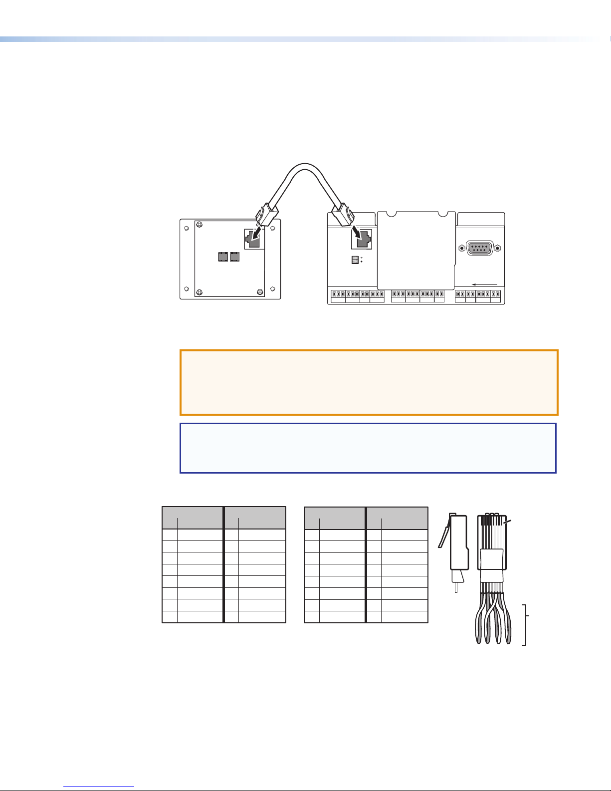
Intercom port (IPI 101 AAP and IPI 104 AAP only) (see figure 2 on page 6) — This port
A
is used for power, control, and voice data communication with the MLC.
• Plug one end of a standard, straight through, CAT 5, CAT 5e, or CAT 6 cable terminated
with RJ-45 connectors into this port (see figure 4, below).
• Plug the other end of the cable into the Intercom connector on the MLC 226 IP rear
panel, as shown in figure 3.
<100’ (30.4 m)
IPI 101 AAP or IPI 104 AAP
INTERCOM
R
AUDIO
OUT
MLC 226 IP Rear Panel
HOST
CONTROL
1=DIGITAL I/O
2=Tx 3=Rx 5=GND
38400, N, 8, 1
PRESS TAB WITH
TWEEKER TO REMOVE
LAN
Figure 3. Connecting the Intercom Port to the MLC 226 IP
ATTENTION:
• This is not an Ethernet LAN connection. Do not connect these ports to the
Ethernet.
• Il ne s’agit pas d’une connexion LAN Ethernet. Veillez à ne pas connecter ces
ports au réseau Ethernet.
NOTE: A 12 inch (30.5 cm) CAT 6 cable is included with each IPI. If you choose to
terminate your own cable, the cable must be no longer than 100 feet (30.4 m). Cables
must be terminated to the T586A or T586B standard and both ends of a cable must
Pin Wire color Pin Wire color
1 White-orange 1 White-orange
2Orange 2Orange
3 White-green 3 White-green
4 Blue 4 Blue
5 White-blue 5 White-blue
6 Green 6 Green
7 White-brown 7 White-brown
8 Brown 8 Brown
be wired to the same standard (see cable wiring in figure 4).
Patch (straight-through) cable
Side 1 Side 2
Pin Wire color Pin Wire color
Crossover cable
Side 1 Side 2
1 White-orange 1 White-green
2Orange 2Green
3 White-green 3 White-orange
4 Blue 4Blue
5 White-blue 5 White-blue
6 Green 6Orange
7 White-brown 7 White-brown
8 Brown 8 Brown
Side
Clip Down
12345678
1
2345678
Pins
RJ-45
connector
Tw
Pairs
Figure 4. RJ-45 Wiring
AAP mounting screws (see figure 2) — These four screws are permanently attached to
B
the IPI faceplate. They are used for mounting the faceplate into another device (such as an
MLC 226 IP AAP) or a mounting frame.
1&2
IPI 100 and IPI 200 Series • Installation 7
7&8
Page 16

IPI 201 and IPI 204 Models Only
LAN port (IPI 201 AAP and 204 AAP only) (see figure 2 on page 6) — Plug an RJ-45
C
jack into the LAN connector to connect to a network. The blinking yellow LED indicates LAN
activity. The green LED lights to indicate a good LAN connection. For wiring, see figure 4 on
the previous page.
Power (see figure 2) — Connect a cable between the 2-pole, 3.5,mm captive screw
D
connector and a 12 VDC, 1 A power supply (included).
ATTENTION:
• If not provided with a power supply, this product is intended to be supplied by
a UL Listed power source marked “Class 2” or “LPS” and rated output 12V dc,
minimum 1.0 A minimum.
• Si le produit n’est pas fourni avec une source d’alimentation, il doit être alimenté
par une source d’alimentation certifié UL de classe 2 ou LPS, avec une tension
nominale 12 Vcc, 1 A minimum.
• The power supply shall not be permanently fixed to the building structure or
similar structures.
• La source d’alimentation ne devra pas être fixée de façon permanente à une
structure de bâtiment ou à une structure similaire.
• Do not place the power supply within environmental air handling spaces or the
wall cavity.
• Ne pas placer les sources d’alimentation dans une zone de traitement de l’air ni
dans une cavité murale.
• The installation shall be in accordance with the applicable provisions of the
National Electrical Code ANSI/NFPA 70, Article 725 and the Canadian Electrical
Code, Part 1, Section 16.
• Cette installation doit toujours être conforme aux dispositions applicables
du Code américain de l’électricité (National Electrical Code) ANSI/NFPA 70,
article 725, et du Code canadien de l’électricité, partie1, section16.
• The power supply is to be located within the same vicinity as the Extron
equipment in an ordinary location, Pollution Degree 2, secured to the equipment
rack within the dedicated closet, podium or desk.
• La source d’alimentation doit être située à proximité de l’équipement de
traitement audiovisuel dans un endroit ordinaire, avec un degré2 de pollution,
fixé à un équipement de rack à l’intérieur d’un placard, d’une estrade, ou d’un
bureau.
Contact Relay (see figure 2) — The 2-pole, 3.5,mm captive screw contact relay connector
E
is used to control items such as room lighting, window coverings, and door locks. The
contact may be used to control any equipment as long as the contact specifications of 24
VDC at 1 A are not exceeded.
Audio Out (see figure 2) — A 3-pole, 3.5 mm captive screw connector is used for audio
F
output connection. It provides a -10 dBV balanced or unbalanced signal that can be
connected to local, powered speakers or to any audio or paging system.
IPI 100 and IPI 200 Series • Installation 8
Page 17

MLC Audio Connection
To
Au
Pa
The MLC 226 IP Series controllers that support IPI intercom panels also have a rear panel, line
level audio output port that can be connected to local, powered speakers or to any audio or
paging system. See the wiring guide in figure 5, below.
a Speaker,
dio System, or
ging System
Figure 5. MLC Audio Connection
NOTE: The volume for this audio output can be adjusted via software only.
Sample Applications
There are several ways to make use of an IP Intercom System. To see what you can do with the
IPIs, look at the sample scenarios provided in this section.
Single PC to Panel
For a simple intercom system, connect one or more panels to a PC that serves as the help desk
console.
Help Desk Console
IP 10.XX.XX.01
To /from the IPI 104 AAP
or IPI 101 AAP
Rear Panel Intercom Port
+
Captive Screw
Connector
Do not tin the wires!
MLC 226 IP Rear Panel MLC 226 IP Rear Panel
INTERCOM
R
AUDIO
OUT
Audio
Card
IP 10.XX.XX.04
PROJECTOR
AUTO
ON
OFF
IMAGE
VCR
1
VOLUME
MUTE
4
LAPTOP
IR
MLC 226 IP AAP
INTERCOM
AUX
DVD
VIDEO
3
2
5
6
PC
CONFIG
IPI 104 AAP
Office
PUSH TO CALL
HELP
LAB
SECURITY
DESK
1 234
MIC ON
ADMIN
OFFICE
IPI 104
MLC 226 IP
TCP/IP
Network
Classroom
IP 10.XX.XX.02
INTERCOM
PROJECTOR
AUTO
ON
OFF
IMAGE
AUX
DVD
VCR
VIDEO
3
2
1
VOLUME
MUTE
5
6
4
LAPTOP
PC
IR
CONFIG
MLC 226 IP AAP IPI 101 AAP
MIC ON
PUSH
HELP
TO
DESK
CALL
IPI 101
MLC 226 IP
Straight-through
Network Cable
Lab
IP 10.XX.XX.03
INTERCOM
PROJECTOR
AUTO
ON
OFF
IMAGE
AUX
DVD
VCR
VIDEO
3
2
1
VOLUME
MUTE
5
6
4
LAPTOP
PC
IR
CONFIG
MLC 226 IP AAP IPI 101 AAP
MIC ON
PUSH
HELP
TO
DESK
CALL
IPI 101
MLC 226 IP
Figure 6. Single PC to One or More Panels
IPI 100 and IPI 200 Series • Installation 9
Page 18

1. Connect one or more IPI 201, IPI 204, or MLC226IP units with any combination of one or
IP 10.XX.XX.03
IP 10.XX.XX.02
IP 10.XX.XX.01
more IPI 101 AAP or IPI 104 AAP units to a network using straight-through cable.
2. Using a PC on the same network, configure the IPI systems. Configure one button on each
IPI with the IP address of the PC by one of the following methods:
• using Global Configurator
• using the unit web pages
• using the ARP command.
The button light changes from red to low amber to indicate it is configured and connected to
the PC.
3. The intercom user presses and holds the button assigned to the PC to initiate talk mode.
The button glows bright amber, and the MIC ON LED lights.
4. The user speaks into the intercom. Audio is output through the PC speakers at the help
desk console.
5. The intercom user releases the button after speaking.
6. The console operator clicks the Talk button (in the software) or presses the space bar on
the PC keyboard to respond.
Multiple PCs to Panel
Some facilities may require a system with more than one console PC. For example, the first could
be staffed by a computer applications expert, the second by security personnel, and the third
by resource aides or lab stockroom staff. Each console is configured to connect with several
intercoms, and each intercom is configured to contact up to four consoles.
Audio
Card
Classroom
Help Desk
IP 10.XX.XX.04
INTERCOM
PROJECTOR
ON
AUTO
OFF
IMAGE
AUX
DVD
VCR
VIDEO
3
2
1
VOLUME
MUTE
5
6
4
LAPTOP
PC
IR
CONFIG
MONITOR
PUSH
HELP
TO
DESK
CALL
MLC 226 IP AAP IPI 101 AAP
Figure 7. Multiple PCs to Multiple Panels
1. Connect one or more PCs to the network and install the IP Intercom HelpDesk Software on
each PC. If call forwarding is used, Extron recommends that no more than six PCs should
be set up for call forwarding.
See Help Desk Software, starting on page 21, for instructions on how to install and use
the software.
2. Connect up to a maximum of 250 intercoms (per help desk PC) to a network using
straight-through cable. Extron recommends that large systems should be segmented, so
that no more than 60 intercoms are associated with a single help desk.
MIS
Classroom
IP 10.XX.XX.05
PROJECTOR
AUTO
ON
OFF
IMAGE
VOLUME
MUTE
IPI 101
MLC 226 IP
MLC 226 IP AAP IPI 104 AAP
Audio
Card
DVD
VCR
1
4
LAPTOP
IR
AUX
VIDEO
3
2
5
6
PC
CONFIG
TCP/IP
Network
PUSH TO CALL
MLC 226 IP
Campus
Police
IP 10.XX.XX.06
PUSH TO CALL
IPI 204
Audio
Card
Lab
Chem Lab
Stockroom
Straight-through
Network Cable
Office
IP 10.XX.XX.07
PUSH
TO
CALL
IPI 201
IPI 100 and IPI 200 Series • Installation 10
Page 19

3. Configure the intercoms and set up the intercom list for each console PC. Each console
could be set up to monitor a different group of intercoms, but most likely the lists will overlap.
In the example shown in figure 7, on the previous page, an installation in one building of a
college campus, each room (classroom, lab, or office) contains an intercom.
Configure one button on each intercom to contact the computer help desk. For IPI104 or
IPI204 models, configure a second button on each intercom to contact the campus security
department. However, only the intercoms located in physical sciences classrooms and
laboratories have a third button configured to contact the PC console in the lab stockroom.
Only the intercoms installed in offices have a button configured to call the registration
department console.
4. Once the system is configured, each intercom user presses and holds a button to initiate talk
mode. The button glows bright amber, and the MONITOR LED lights.
5. The user speaks into the intercom. Audio plays through the speakers or headset at the
console the pressed button was configured to call.
6. The intercom user releases the button after speaking.
7. The console operator clicks the Talk button (in the software) or presses the space bar on
the PC keyboard to reply.
Panel-to-Panel Mode
You do not need to include a console PC as a permanent part of an IP Intercom System. In this
example, panels are configured to communicate directly with each other. The software does not
need to be running during intercom system operation.
NOTE: Panel to panel mode works only when both panels are in the same network subnet.
Configuration Console PC
IP 10.XX.XX.01
Connect for configuration.
This connection is not
needed for later operation.
TCP/IP
Network
Straight-through
Network Cable
Classroom
IP 10.XX.XX.02
INTERCOM
PROJECTOR
AUTO
ON
OFF
IMAGE
AUX
DVD
VCR
VIDEO
3
2
1
VOLUME
MUTE
5
6
4
LAPTOP
PC
IR
CONFIG
MLC 226 IP AAP IPI 101 AAP
MIC ON
PUSH
HELP
TO
DESK
CALL
IPI 101
MLC 226 IP
IP 10.XX.XX.03
PROJECTOR
AUTO
ON
OFF
IMAGE
AUX
DVD
VCR
VIDEO
2
1
VOLUME
MUTE
5
4
LAPTOP
IR
CONFIG
MLC 226 IP AAP IPI 101 AAP
Lab
INTERCOM
MIC ON
3
6
PC
PUSH
HELP
TO
DESK
CALL
IPI 101
MLC 226 IP
Figure 8. Panel to Panel Mode
1. Connect two IPI 101 AAPs and their MLC 226 IPs to a network using straight-through cable.
2. Using a PC connected to the same network (see figure 8), configure the two IPI systems.
See Help Desk Software, starting on page 21, for instructions on how to use the
HelpDesk software for configuration.
3. Close the configuration program. The PC can be disconnected from the network or used for
other functions.
4. Push the button on one IPI to contact the other IPI. On the calling IPI, the microphone is
enabled, the MIC ON LED lights, and the button light changes from low amber to bright
amber. On the IPI being called, the button light changes from low amber to bright amber.
IPI 100 and IPI 200 Series • Installation 11
Page 20

Server Mode
IP 10.XX.XX.03
IP 10.XX.XX.02
IP 10.XX.XX.01
A single PC can act as a server to control the communication between the intercoms and the
Help Desks. For complete instructions about configuring a computer as a server or as a client
help desk, see Help Desk Software, starting on page 21.
Audio
Card
MIS
Help Desk
Audio
Card
IP 10.XX.XX.04
TCP/IP
Network
TCP/IP
Network
Campus
Police
Server
Audio
Card
Chem Lab
Stockroom
Straight-through
Network Cable
Classroom
IP 10.XX.XX.05
INTERCOM
PROJECTOR
AUTO
ON
OFF
IMAGE
AUX
DVD
VCR
VIDEO
3
2
1
VOLUME
MUTE
5
6
4
LAPTOP
PC
IR
CONFIG
MLC 226 IP AAP IPI 101 AAP
MONITOR
PUSH
HELP
TO
DESK
CALL
Classroom
IP 10.XX.XX.06
PROJECTOR
AUTO
ON
OFF
IMAGE
VOLUME
MUTE
IPI 101
MLC 226 IP
MLC 226 IP AAP IPI 104 AAP
IP 10.XX.XX.07
Lab
AUX
DVD
VCR
VIDEO
3
2
1
5
6
4
LAPTOP
PUSH TO CALL
PC
IR
CONFIG
MLC 226 IP
PUSH TO CALL
IPI 204
PUSH
CALL
Office
IP 10.XX.XX.08
TO
IPI 201
Figure 9. Server Mode
1. Configure one computer as a server. Ensure that all intercoms are listed in the intercom list
of the server and each HelpDesk. Also ensure that all HelpDesks in the system are on the
server list of Cooperating Help Desks.
2. Configure one of the buttons on each intercom to communicate with the server.
3. Configure all of the Help Desk PCs so that only the server is listed on the list of Cooperating
Help Desks.
4. Set the server to server mode and restart the IPI program on the server.
Any call from an intercom will now be routed by the server to an available Help Desk. For
complete instructions on setting up server and client PCs, see Setting up one PC as a
server, starting on page 33.
IPI 100 and IPI 200 Series • Installation 12
Page 21

Intercom with Amplifier
MP
IPI 201
The MLC Audio Out 2-pole captive screw connector outputs a -10 dBV audio signal that can be
routed to an external audio amplifier and speakers, as shown in figure 10.
1. Cable the system as shown in figure 10.
MPA 152
C US
DO NOT GROUND
LISTED
17TT
SPEAKER OUTPUTS!
AUDIO/VIDEO
APPARATUS
POWER
12V
3A MAX
A 152
Figure 10. Intercom with an Amplifier
2. Power on the equipment.
3. Make fine adjustments to output level using the Remote Line slider in the Advanced Settings
part of the HelpDesk software (see the HelpDesk Software Help File). The external amplifier
must be adjusted properly to avoid any audio signal clipping or audio distortion.
4. If desired, use the software to adjust to minimum levels the IPI speaker output.
INPUTS
L
R
CLASS 2 WIRING
OR SHORT
SI 3CT LP
OUTPUT
4/8
OHMS
R
L
REMOTE
R
L
VOL/MUTE
10V50mA
Ceiling
Speakers
CNO
POWERRELAY
AUDIO OUT
LAN
IPI 100 and IPI 200 Series • Installation 13
Page 22

Operation
IPI 204 AAP
IPI 201 AAP
This section describes:
• Front Panel Features and Operation
• Button Operation
Front Panel Features and Operation
B
B
INTERCOM
MIC ON
INTERCOM
MIC ON
AA
D
D
CONFIG
PUSH
TO
CALL
HELP
DESK
IPI 201
PUSH TO CALL
HELP
ROOM
DESK
101
1234
CONFIG
ADMIN
LAB
OFFICE
IPI 204
C
C
E
E
Figure 11. Front Panels
Speaker — This integrated speaker provides mono output at the IPI panel.
A
Mic On LED — This LED lights under two circumstances:
B
• When a configured PUSH TO CALL button is pressed.
• To indicate that someone at the help desk console is listening and that the intercom is
in monitoring mode. Monitoring mode permits hands-free operation: the user does not
have to press the Push to Talk button to speak into the intercom. It also lets help desk
staff monitor what is happening to determine whether to send security personnel to that
room.
Microphone — Push one of the butttons and talk. The microphone is behind this opening.
C
Config Port (IPI 200 Series only) — This 2.5 mm port is used to configure the IPI201 and
D
IPI 204 and to upload firmware when necessary.
Push to Talk buttons — The IPI 101 AAP and IPI 201 units include one of these buttons,
E
and the IPI 104 AAP and IPI 204 units have four.
NOTE: The MLC and IPI intercoms must be configured (via software) to associate each
button with the IP address of a specific console PC or intercoms. Once configured,
the IPI 101 AAP and IPI 201 can communicate to one location (one IP address). The
IPI 104 AAP and IPI 204 can communicate with up to four different locations.
IPI 100 and IPI 200 Series • Operation 14
Page 23

Button Operation
Push to Call Operation
Press a PUSH TO CALL button to call the help desk or another console. That enables the
microphone, causes the MIC ON LED to light, and enables communication to the location
associated with that button. When pressed, the button lights bright amber.
• If the console PC being called is busy, the IPI plays a .wav file to tell the caller that the line
• If the console PC being called is not connected to the network, the IPI plays a .wav file
• Once a call is successfully connected, press and hold the button when you speak, and
NOTE: You must press and hold an IPI button to speak and to call the help desk or another
Indication (Lighting)
Button Color Indication
is busy. A “call received” message appears at the help desk console PC to indicate that the
intercom is calling. For informaton about .wav files, see Loading a Pre-recorded .wav File
on page 31 for information about using .wav files.
stored on its local MLC to notify the intercom user that the connection is not available. Also,
the button lights red instead of amber.
release it to allow the other party to speak.
intercom. When you release the button, the intercom microphone turns off unless the help
desk is listening (see Listen Mode on page 29).
Amber (dim)
• The button is in standby.
• The device at the IP address associated with that button is
turned on and is connected to the network. If that device gets
disconnected or if the help desk software is not running on that
PC, the button lights red. Once it is reconnected, the button
returns to dim amber lighting.
Amber (bright)
• The IPI is communicating with the location the button is
configured to call. This happens during a call, a page, or when
receiving an announcement from the console PC.
Red
• The device (console) associated with the button is disconnected
from the network or is turned off.
• The software is not running or has been closed.
IPI 100 and IPI 200 Series • Operation 15
Page 24

Initial
IPI 200 Series
Left Side
Configuration
The IPI 100 Series units must be connected to a MLC 226 IP MediaLink controller with a valid IP
address. See the MLC 226 IP User Manual for information about configuring the IP address of
the MLC controller.
The IPI 200 Series units have a factory default IP address of 192.168.254.254. This IPaddress
must be changed to an address that will operate on your local network.
This section discusses:
• Before You Begin
• Setting the IP Address Using Global Configurator
• Setting the IP Address Using Embedded Web Pages
• Setting the IP Address Using the ARP Command
Before You Begin
1. Obtain an IP address for the IPI 200 Series device from the AV system network administrator.
2. Write down the unit MAC address (a 12-digit number) found on a label on the rear panel of
the unit (for example, 00-05-A6-01-0A-74).
3. If the unit IP address has been changed from the factory default (192.168.254.254),
before setting a new IP address, the default IP address must be restored by performing a
Mode 4 reset:
Figure 12. Reset Button
a. Hold down the RESET button on the left side of the unit (see figure 12, above) until the
Power LED blinks twice (6seconds), then release.
b. Press and release the RESET button again within 1 second.
The Power LED blinks quickly four times, confirming the Mode 4 reset, which returns the
unit to its factory default IP address.
RESET
RESET
NOTE: The RESET button is recessed. Activate it with an Extron Tweeker or similar
tool.
IPI 100 and IPI 200 Series • Initial Configuration 16
Page 25

Setting the IP Address Using Global Configurator
The preferred method for setting a unit IP address is to use Extron Global Configurator (GC)
application.
If you have Global Configurator installed on a local PC, and have a GC project file open, proceed
with the steps below. If you do not have Global Configurator installed, it is available as a free
download from www.extron.com. The Global Configurator Help File steps you through the
process of creating a new GC project file, and provides an illustrated version of the procedure
below.
NOTE: You must use Global Configurator (version 3.3 or later) to configure the IPI unit. Do
not use Global Configurator Plus and Professional.
Before setting the IP address with Global Configurator:
• The IPI 200 Series intercom unit must be physically connected to the network or connected
directly to a computer via the front panel CONFIG port.
• The IP address of the IPI 200 Series intercom unit must be set to the factory default.
To set an IP address with a GC project file open:
1. From the Edit menu, select Add Device.
The Add Device dialog box opens:
11
4
2
2
5
5
67
6
3
3
4
7
88
Figure 13. Global Configurator Add Device Dialog
2. Select the appropriate device type (for example, the IPI 204) in the IP Link Device drop-
down list (1).
3. Enter the new IP address (for example, 192.168.254.251) in the Name/IP Address field
(2).
4. Enter a unique device name in the Display Name field (
5. Click Advanced >>> (
displayed, Advanced >>> changes to Basic <<<.
6. Click the Auto Configure IP Address checkbox (
7. Enter the unit MAC address in the MAC Address field (
pre-populated, and identify this unit as an Extron device. You only need to enter the final six
digits. Dashes between digits are auto-filled.
8. Click Set (
9. Click OK (
). The Auto Configure Successful dialog box opens.
7
).
8
). When the Advanced options of the Add Device dialog are
4
).
3
).
5
). The first six digits (00-05-A6) are
6
IPI 100 and IPI 200 Series • Initial Configuration 17
Page 26
Setting the IP Address Using Embedded Web Pages
Each IPI 200 Series intercom unit contains an on-board web server with interactive pages that
can be used to configure the device.
The intercom unit must be at its factory default IP address.
To set an IP address via embedded web pages:
1. Connect an Ethernet crossover cable between the device and a local PC.
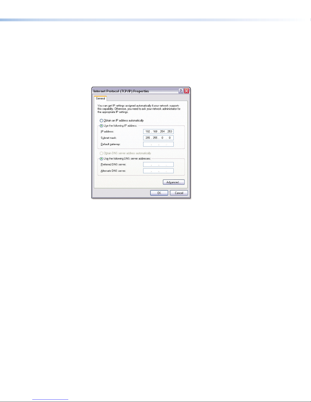
2. On the PC, locate the TCP/IP Properties dialog box.
Figure 14. TCP/IP Properties Dialog
3. Record the current IP address, subnet mask, default gateway and DHCP settings.
You will need this information later to return the PC to its original TCP/IP settings.
4. Enter the following:
• IP address: 192.168.254.253
• Subnet mask: 255.255.0.0
• Leave the Default gateway field blank
5. Click OK.
6. Open a web browser on the local PC.
IPI 100 and IPI 200 Series • Initial Configuration 18
Page 27

7. Enter 192.168.254.254 in the browser Address field and press <Enter>.
The embedded web page for the intercom unit is displayed.
11
2
2
3
3
Figure 15. Embedded System Settings Web Page
8. Click the Configuration tab (
9. Enter the desired values in the IP Address and Subnet Mask fields (
10. Click Submit (
the connection is lost. The device can now be connected to your AV network.
To return the local PC to its original TCP/IP settings:
1. Close the web browser.
2. Disconnect the Ethernet crossover cable from the PC and the device.
3. Return to the TCP/IP Properties dialog box on the PC.
4. Return the IP address, Subnet mask, Default gateway, and DHCP fields to their original
settings.
5. Reboot the PC.
). Once the new IP address and subnet mask are assigned to the device,
3
1
).
).
2
IPI 100 and IPI 200 Series • Initial Configuration 19
Page 28

Setting the IP Address Using the ARP Command
The IP address for an IPI 200 Series unit can be set using the DOS Address Resolution Protocol
(ARP) command. Before setting the IP address with the ARP command:
• The IPI 200 Series intercom unit must be physically connected to the network or connected
directly to a computer via the front panel CONFIG port.
• The IP address of the IPI 200 Series intercom unit must be set to the factory default.
To set an IP address using the ARP command:
1. Open a command prompt window on a local PC.
2. At the command prompt enter:
arp -s <IP address> <MAC address>
(for example: C:\>arp -s 192.168.254.254 00-05-A6-00-30-5F where the IP address
192.168.254.254 is assigned to the device with the MAC address 00-05-A6-00-30-5F.
Figure 16. Command Prompt
3. To confirm the new IP address is active, perform a ping command to the new IP address.
for example: C:\>ping 192.168.254.254
If the IP address setting was successful, the device replies 3 or more times:
Reply from 192.168.254.254: bytes=32 time <1ms TTL=64
IPI 100 and IPI 200 Series • Initial Configuration 20
Page 29

Help Desk
Software
This section discusses:
• Introduction to the Software
• System Requirements
• Installing the Software
• Starting the Program
• Configuring the IP Intercom System
Introduction to the Software
The IP Intercom System requires a PC running the IP Intercom HelpDesk software and an IP
Intercom unit. The HelpDesk program (provided on the software disk) has a management and
monitoring application (the main screen) and a configuration utility.
If an IPI 100 series unit is used, it must be linked to an MLC 226 IP controller. The IPI 200 series
are stand-alone units that do not need to be connected to another MediaLink device.
The PC, the IPI 200 series unit, and the MLC 226 IP, when used with an IPI 100 series unit, must
all be connected to the Local Area Network (LAN) and each must have a unique IP address.
Consult with your IT department to ensure that IP addresses have been correctly allocated.
Network and IT administrators should use information from the following white papers, which can
be found at www.extron.com, to ensure optimal network configuration and compatibility for the
IP Intercom system:
• IP Intercom Network Impact Statement
• IP Intercom Best Installation Practices
Extron recommends that the IP Intercoms and the HelpDesk be on the same LAN with a static
IP address and not be separated by a firewall.
If the IP addresses are on different subnets, it is best to set up a dedicated VLAN. If a firewall is
required, the following ports need to be open:
• UDP port 3121 (audio traffic)
• TCP telnet port 23 (control and status)
• UDP port 3122 (inter-helpdesk communication)
• UDP ports 1230 and 1231 (auto discovery)
If you are using an IPI 100 series unit, linked to an MLC 226 IP controller, you must configure the
MLC for network communication before you can install and use the intercom system software.
For more information about configuring the MLC, see
• “Software-and web page-based Setup and Control“ in the MLC 226 Series User Manual
• The Global Configurator Help File (automatically downloaded and installed along with the
Global Configurator software)
IPI 100 and IPI 200 Series • Help Desk Software 21
Page 30
System Requirements
Before installing the IP Intercom program, ensure that your computer system meets the minimum
requirements (System Requirements (see page 4)).
Installing the Software
To install the IP Intercom software on the hard drive:
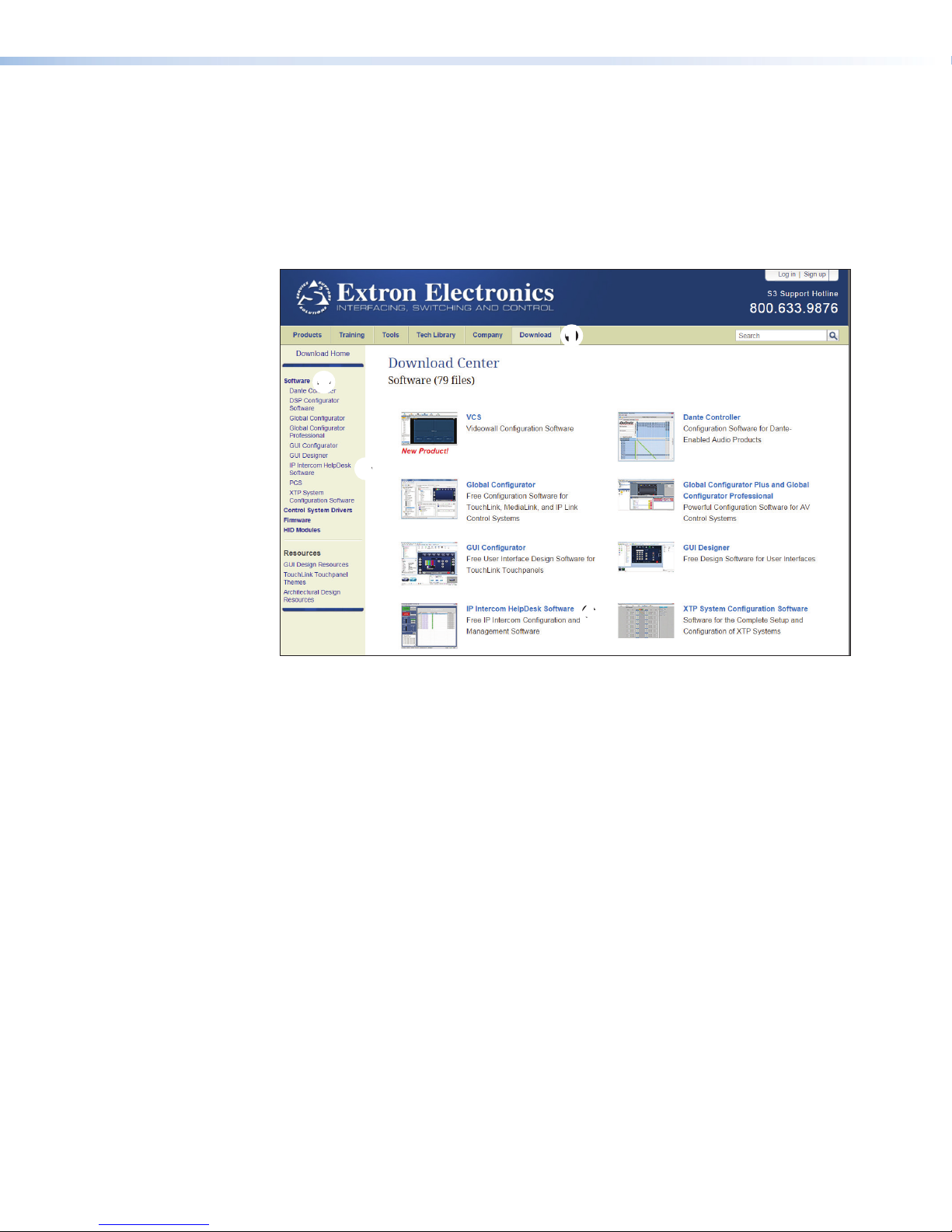
1. Open the Extron web site (www.extron.com).
2
2
3
3
11
4
4
Figure 17. Extron Software Download Page
2. Click the Download tab at the top of the page (
3. Click the Software link in the sidebar (
4. Click IP Intercom HelpDesk Software in the sidebar (
If you do not see this option, scroll down to the alphabetic menu, Click I, and navigate to
IP Intercom HelpDesk.
The IP Intercom HelpDesk Software page opens.
5. Click Download on the main product page and follow the on screen instructions.
The IP Intercom HelpDesk software is installed on the PC. By default the directory is
C:\Program Files\Extron\IPI.
The IPI icon is added to the desktop and a program shortcut is added to the Start menu in
the Extron Electronics folder.
2
).
1
).
) or on the main page (4).
3
IPI 100 and IPI 200 Series • Help Desk Software 22
Page 31
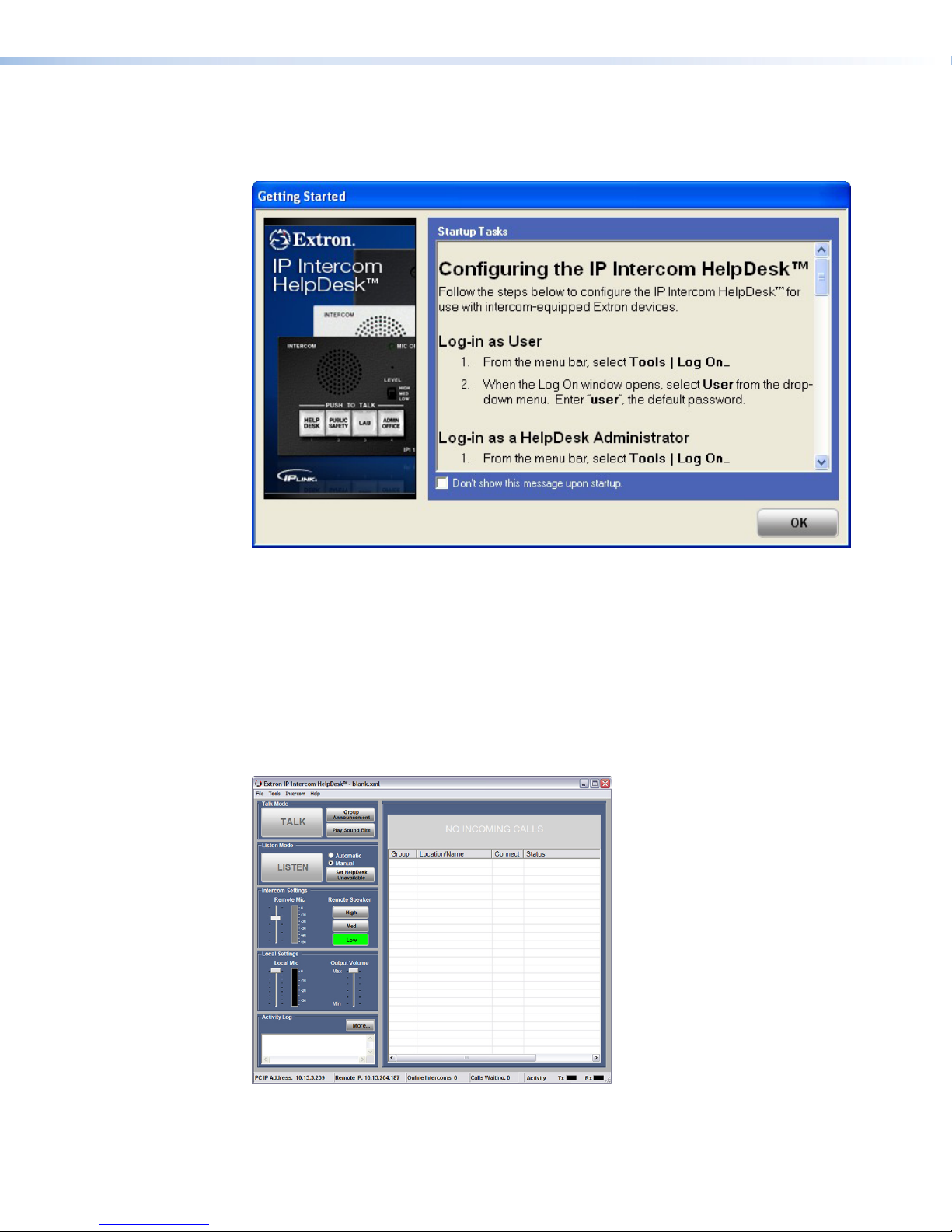
Starting the Program
Open the software by clicking the desktop icon, using Windows Explorer, or the Start menu.
The program opens with the Getting Started pop-up screen displayed:
Figure 18. IP Intercom HelpDesk Software Getting Started
Use the scrollbar to find basic information about:
• Log-in as User
• Log-in as a HelpDesk Administrator
• Change the Password
• Set Up Intercom-equipped Extron Devices
If you do not wish to see this window when you open the program in the future, check the Don’t
show this message upon startup checkbox.
To close the pop-up window, click OK.
The main program window can now be seen:
Figure 19. IP Intercom HelpDesk Software Main Page
IPI 100 and IPI 200 Series • Help Desk Software 23
Page 32

The following section provides step by step procedures for some of the most common
operations performed with the IP Intercom system. For details about operations not shown here,
see the IP Intercom HelpDesk Help File, which can be accessed by clicking Help in the Help
menu or by pressing <F1> from within the HelpDesk program.
Configuring the IP Intercom System
This section takes you through the step-by-step procedures for carrying out certain basic tasks.
The examples in this chapter specifically describe the IPI 204 devices but apply to all IP Intercom
models.
For information about more advanced setup and configuration, consult the IP Intercom HelpDesk
Help File, which can be accessed by clicking Help in the Help menu or by pressing <F1> from
within the HelpDesk program.
Basic Configuration
Using the Configuration Utility
1. In the Tools menu, select Configuration Utility. The first time the utility is used after
opening the program a Password pop-up box appears. Enter a password. The default
password is extron (all lower case letters).
2. The Configuration Utility window opens:
Figure 20. Configuration Utility
3. Create a list of intercom devices. This can be done by:
• Importing a GC2/GCZ file on page 25, using Global Configurator
• Entering the IP addresses manually on page 25
• Automatically scanning the local subnet on page 26
Use the drop-down menu to select the appropriate option.
IPI 100 and IPI 200 Series • Help Desk Software 24
Page 33

Importing a GC2/GCZ file
12
1. Select Import GC2/GCZ List (recommended) from the drop-down menu.
2. Click Import. An Open dialog box opens.
Figure 21. Open Dialog Box
3. Navigate to the folder where you have saved the Global Configurator file and select it.
4. Click Open. The Intercom List is updated using devices from the Global Configurator file.
5. Go to Configuring an IP Device with the Configuration Utility on page 27.
Entering the IP addresses manually
3
3
1
4
4
Figure 22. Enter the IP Addresses Manually
1. Select Manually by IP Address from the drop-down menu (
2. Enter an IP address in the text box (
3. The Import button is renamed Add. Click Add (
4. The new IP address appears on the Intercom List (
device a name.
5. Click Update Intercom List to save the device.
6. Go to Configuring an IP Device with the Configuration Utility on page 27.
2
).
3
2
).
1
).
) and you are prompted to give the
4
IPI 100 and IPI 200 Series • Help Desk Software 25
Page 34

Automatically scanning the local subnet
1. Select Automatic (Local Subnet Only) from the drop-down menu.
2. The Add button is renamed to Scan. Click Scan.
NOTE: The computer only scans the local subnet for available intercoms.
3. A Scan Progress dialog box opens, indicating the progress of the scan.
Figure 23. Scanning the Local Subnet
4. The scan detects only intercoms that are on the same local subnet and adds them to the
Intercom List.
5. Click Update Intercom List to save the devices that have been added to the list.
6. Go to Configuring an IP Device with the Configuration Utility on page 27.
IPI 100 and IPI 200 Series • Help Desk Software 26
Page 35

Configuring an IP Device with the Configuration Utility
1. Open the configuration utility and select one of the IP devices in the Intercom List.
2. When it is highlighted, its information is displayed in the Selected Intercom panel:
Figure 24. Configuration Utility
3. In the Selected Intercom panel, the unit administrator password and the IP addresses
associated with each of the four buttons on the intercom can be changed.
4. Click Apply to save the changes.
5. Click Exit to close the configuration utility.
IPI 100 and IPI 200 Series • Help Desk Software 27
Page 36

Talk Mode
1. Select one of the IP devices on the Intercom List in the main screen.
2. To activate Talk mode, left-click TALK and hold down the mouse button or by press and hold
down the keyboard spacebar. The label on the button changes to TALKING.
3. Speak into the headset microphone. The Local Mic VU meter oscillates in response to the
audio being picked up by the microphone.
4. To end talk mode, click TALKING, or release the mouse or the spacebar.
Figure 25. Talk Mode On
IPI 100 and IPI 200 Series • Help Desk Software 28
Page 37

Listen Mode
1. In the Tools menu open the
HelpDesk Preferences dialog
box and click on the User
Options tab.
2. Select the Play recurring
alert tone at intercom
panel when panel mic is
open and Play alert tone at
intercom panel when mic is
opened or closed options (they
are both selected by default).
Figure 26. HelpDesk Preferences Dialog Box
3. Close the HelpDesk Preferences
dialog box.
4. Select an IP device on the Intercom
List.
5. Activate the LISTEN button. The label
on the button changes to LISTENING,
the intercom button turns from low
amber to high amber color, two
audible signals of different frequencies
are heard at the intercom to indicate
that the intercom mic is opened, and
the green MIC ON LED lights.
6. Start speaking. While the LISTENING
button is active, an audible signal is
heard every ten seconds.
7. Deselect the Listening button. The
button on the intercom returns to a low
amber color. A single audible signal is
heard at the intercom.
Figure 27. Listen Mode On
8. Press and hold the intercom button. It turns to a high amber color and the MIC ON LED lights
green. On the PC monitor, the LISTEN button is activated, the “Incoming Call Alert” indicator
flashes, and two audible signals of different frequencies are heard at the intercom.
9. Release the intercom button. It turns to a low amber color and the MIC ON LED turns off.
IPI 100 and IPI 200 Series • Help Desk Software 29
Page 38

Group Announcement
1. Decide which IP devices on the
Intercom List you wish to group
together. Select each device one at a
time and use the Group drop-down
menu to assign all of them to the same
group.
NOTE: Each device on the
Intercom List can only belong
to one group.
2. Click the Group Announcement
button.
3. The Group Selection panel becomes
visible. Groups that are available are
listed in black text; groups that are
not available are grayed out. Select an
available group or All Intercoms.
4. The selected button turns green and
the intercom devices belonging to that
group are highlighted in the Intercom
List.
5. Activate the Talk mode (Talk Mode
starting on page 28). When you have
finished talking inactivate the Talk mode.
or
Click Play Sound Bite. A list of
available sound bites appears. (For
information about managing the Sound
Bites list, Loading a Pre-recorded
.wav File starting on page 31) Select
the sound bite and click Play to
Intercom(s). The button turns green
and the text changes to Stop Playing.
6. When the sound bite has finished
playing, click Exit.
7. Close the Group Selection panel by
clicking Exit.
Figure 28. Group Selection
Figure 29. Sound Bite Selection
IPI 100 and IPI 200 Series • Help Desk Software 30
Page 39

Loading a Pre-recorded .wav File
The software allows you to load up to ten pre-recorded .wav files. The software comes with a
library of .wav files in the C:\ProgramFiles\Extron\IPI\wav folder. You can use these .wav
files or record your own messages. For example, non-English speakers may find it easier to have
the files in their native language. After recording the .wav file, it should be saved in the same
folder.
NOTE: The .wav file must be saved as 8 kHz, 16 bit, mono audio in PCM format.
To load a pre-recorded file:
1. Open the configuration utility. Under the Tools menu, select the Manage Sound Bites
option.
Figure 30. Manage Sound Bites Dialog Box
2. Click on the file button ( ) and go to C:\Program Files\Extron\IPI\wav
folder. Select the .wav files that you wish to be available.
3. Click OK to close the Manage Sound Bites box and then click Exit to close the
Configuration Utility.
Changing the Default .wav File for Intercom Events
Certain situations lead to default .wav files being played. It is possible to customize those files.
1. Under the Tools menu, open the Help Desk Preferences dialog box and click on the
Audio tab.
2. For each event, click on the corresponding file button ( ) and navigate to C:\
Program Files\Extron\IPI\wav folder. Select the .wav files that you wish to associate
with that event.
3. As soon as a change is made, an OK button appears. When all the changes have been
made, click OK to close the Help Desk Preferences dialog box.
IPI 100 and IPI 200 Series • Help Desk Software 31
Page 40

Call Forwarding
The IP Intercom HelpDesk provides two ways of handling call forwarding:
1. A single PC, acting as a server, forwards calls to the next available help desk.
2. A peer-to-peer network allows calls to be forwarded to any available help desk.
Setting up a peer-to-peer network
All PCs must be running the IP Intercom HelpDesk software.
1. All PCs must have all available intercoms on their Intercom List.
a. On the first computer, add all intercoms to the Intercom List (see Using the
Configuration Utility starting on page 24).
b. In the File menu, click Save or Save As... to save the .xml configuration project file.
c. On each of the other help desks, in the file drop-down menu, select Load Project.
Load the project file saved in the previous step onto the help desk PC.
2. All intercoms must be linked to the IP address of one of the available help desks:
a. Open the Configuration Utility and select an intercom in the Intercom List.
b. In the Button IP assignments panel, enter the IP address of the server PC or select it
from the dropdown list.
c. Click Apply.
d. Repeat steps a-c until all intercoms have been linked to one of the available help desk
computers.
3. All help desk computers must have a list of all other available help desks, which are added
as follows:
a. Open the Configuration Utility window and, in the Tools menu, click Multiple
HelpDesk Configuration... The HelpDesks dialog box opens (see figure 31).
b. Add the name and IP address of a
HelpDesk in the text boxes at the bottom
of the window.
c. Click Add. The computer is added to the
Cooperating HelpDesks list.
d. Repeat steps b and c until all cooperating
HelpDesks have been added.
NOTE: There is no automated way
to add multiple HelpDesks; they
must be added individually.
e. When all HelpDesks have been added,
click OK.
4. None of the PCs can be set to Server Mode:
a. Under the Tools menu, click
Preferences. The Preferences box
opens.
b. Click the Forwarding tab.
c. Uncheck the Mode box. This box is left
unchecked by default.
d. If necessary, shut down and restart the
IP Intercom HelpDesk program.
IPI 100 and IPI 200 Series • Help Desk Software 32
Figure 31. Adding HelpDesks
Page 41

Setting up one PC as a server
All PCs (the server and the help desks) must be running the IP Intercom HelpDesk software.
1. The server PC and all HelpDesk PCs must have all available intercoms on their intercom list.
a. Add all intercoms to the Intercom List of the computer that has been designated the
server.
b. In the File menu, click on Save or Save As... to save the .xml configuration project
file.
c. On each help desk computer, in the File drop-down menu, select Load Project.
Load the project file saved in the previous step onto the help desk PC.
2. All intercoms must be linked to the IP address of the server:
a. Select an intercom in the intercom list.
b. In the Button IP assignments panel, enter the IP address of the server or select it
from the dropdown list.
c. Click Apply.
d. Repeat steps a-c until all intercoms have been linked to the server.
3. The server PC must have a list of all client HelpDesks. These are added as described in
steps 3a to 3e of Setting up a peer-to-peer network on the previous page.
The first name on the list will be the first choice HelpDesk. If the first PC is busy, the next call
will be passed to the second PC on the list. If all HelpDesks are busy, any new incoming call
will hear a pre-recorded .wav file. This pre-recorded .wav file will usually inform the caller that
all help desks are busy and suggest calling back later.
4. All HelpDesks must be linked to the Server PC:
a. On each HelpDesk PC, open the HelpDesks window as described in step 3a on the
previous page.
b. Add the name and IP address of the server PC in the text boxes at the bottom of the
window.
c. Click Add.
d. Click OK.
2
2
11
5. The server PC must be set to Server
Mode:
a. Under the Tools menu, click
Preferences. The HelpDesk
Preferences box opens (see
figure 29).
b. Click the Forwarding tab (
c. Check the Mode box (
d. An OK button appears.
Click OK (3).
e. Exit and restart the program.
When the program restarts,
the window has changed (see
figure 33 on the following page).
2
1
).
).
3
3
Figure 32. HelpDesk Preferences
IPI 100 and IPI 200 Series • Help Desk Software 33
Page 42
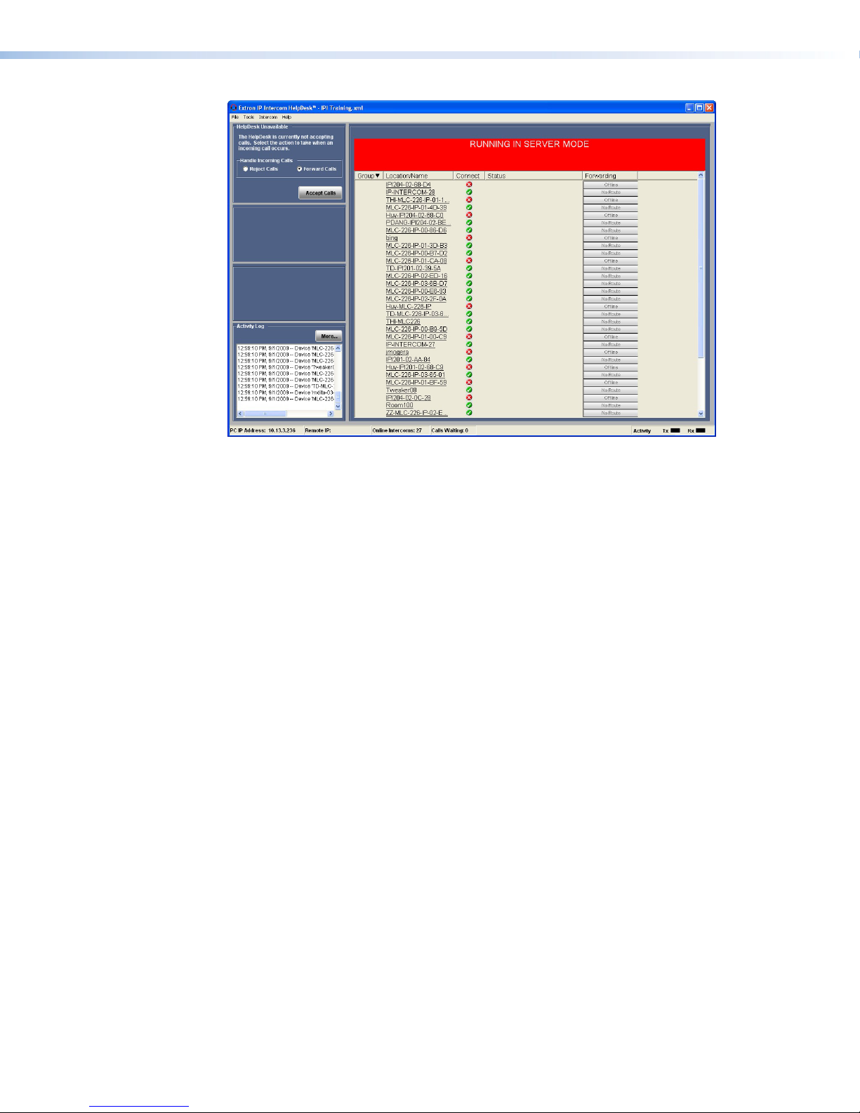
Figure 33. Server Mode
IPI 100 and IPI 200 Series • Help Desk Software 34
Page 43

SIS Programming
and Control
This section of the guide discusses:
• Introduction to SIS
• Host-to-IPI Communications
• IPI-initiated Messages
• Error Responses
• Symbols Used in the Command and Response Table
• Command and Response Table
Introduction to SIS
The Extron MediaLink IP Intercom 201 and 204 modules can be remotely set up and controlled
via a host computer or other device (such as a control system) by using the Extron Simple
Instruction Set (SIS) commands. Connect the module to the host computer via RS-232 or an
Ethernet LAN connection.
NOTE: The following SIS commands are for use with the IPI 201 and 204 models only.
Refer to the MLC 226 IP Series Installation Manual for IPI 101/104 series SIS command
and control information.
IPI RS-232 protocol:
• 38400 baud
• 8 data bits
• 1 stop bit
• No parity
• No flow control
NOTE: The configuration port requires 38400 baud communication. This is a higher speed
than many other Extron products use. If using HyperTerminal or a similar application, make
sure the PC or control system connected to these ports is set for 38400 baud.
LAN port defaults:
• IP address: 192.168.254.254
• Gateway IP address: 0.0.0.0
• Subnet mask: 255.255.0.0
• DHCP: off
NOTE: The IP Intercom (IPI) must be configured before use.
IPI 100 and IPI 200 Series • SIS Programming and Control 35
Page 44

Host-to-IPI Communications
SIS commands consist of one or more characters per field. No special characters are required
to begin or end a command sequence. When the IPI determines that a command is valid, it
executes the command and sends a response to the host device. All responses from the IPI to
the host end with a carriage return and a line feed (CR/LF = ]), which signals the end of the
response character string. A string is one or more characters.
IPI-initiated Messages
If you are communicating with the IPI via RS-232 or via a verbose Telnet connection when a local
event such as a front panel selection or adjustment takes place, the IPI responds by sending a
message to the host. No response is required from the host. The IPI-initiated messages are listed
here (underlined).
(c)Copyright 2007, Extron Electronics, IPI 201 Vx.xx, 60-809-00
Mon Day, DD Mon YYYY HH:MM:SS
(c)Copyright 2007, Extron Electronics, IPI 204, Vx.xx, 60-810-00
Mon Day, DD Mon YYYY HH:MM:SS
where Vx.xx is the firmware version number.
The IPI sends the boot and copyright messages under the following circumstances:
• If the IPI is off and an RS-232 connection is already set up (the PC is cabled to the IPI 200
series unit and a serial terminal emulation program such as HyperTerminal is open), the
connected unit sends these messages via RS-232 when it is first powered on.
• If the IPI is on, it sends the boot and copyright messages when you first open a Telnet
connection to the IPI. You can see the day of the week, date, and time if the IPI is connected
via Telnet, but not via RS-232. If you are using a Telnet connection, the copyright message,
date, and time are followed by a password prompt.
Additional messages may be sent by the IPI in response to front panel selections and volume
adjustments and when scripts are executed during scheduled events.
]
]
Password Information
]
The
carriage return. The prompt is repeated if the correct password is not entered.
If the correct password is entered, the unit responds with
]
administrator and user, the unit will default to administrator privileges.
Password: prompt requires a password (administrator level or user level) followed by a
]
Login Administrator
Login User
]
, depending on the password entered. If passwords are the same for both
]
or
IPI 100 and IPI 200 Series • SIS Programming and Control 36
Page 45

Error Responses
When the IPI receives a valid SIS command, it executes the command and sends a response to
the host device. If the IPI is unable to execute the command because the command is invalid or
it contains invalid parameters, it returns an error response to the host.
The error response codes and their descriptions are as follows:
E12 – Invalid port number
E13 – Invalid value (the number is out of range/too large)
E14 – Not valid for this configuration
E17 – System timed out
E22 – Busy
E24 – Privilege violation
E26 – Maximum number of connections has been exceeded
E27 – Invalid event number
E28 – Bad filename or file not found
E30 – Hardware failure (followed by colon and descriptor number) (unsolicited response.)
E31 – Attempt to break port pass-through when not set
Error Response References
The following superscripted numbers are used within the command descriptions on the following
pages to identify commands that may respond as shown:
14 = Commands that give an E14 (not valid for this configuration) response if the current
configuration of the unit does not support that command.
22 = Commands that yield an E22 (busy) response.
24 = Commands that give an E24 (privilege violation) response if you are not logged in at the
administrator level.
27 = Commands that may yield an E27 (invalid event number) response.
28 = Commands that may give an E28 (file not found) response.
IPI 100 and IPI 200 Series • SIS Programming and Control 37
Page 46
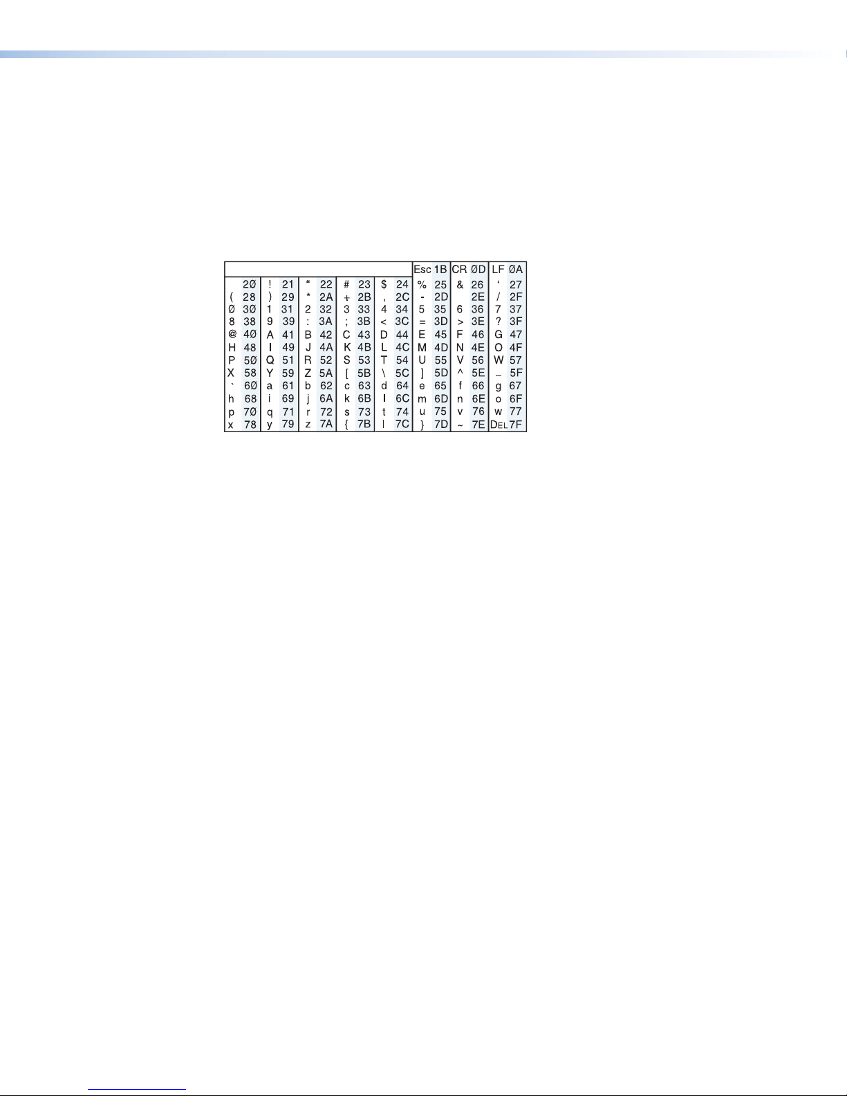
Symbols Used in the Command and Response Table
Space
The IPI 201/204 Series intercom can be controlled via a Telnet (port 23) or RS-232 connection
using ASCII commands. Alternatively, it can be controlled via a web browser (port 80) connection
using URL-encoded commands.
The ASCII and URL commands listed in the Command and Response Table, starting on
page 41, perform the same functions, but they are encoded differently to accommodate the
requirements of each port (Telnet or browser).
The ASCII to hexadecimal (HEX) conversion table shown below is for use with the Command and
Response table.
ASCII to HEX Conversion Ta ble
.
The Command and Response table lists valid ASCII (for Telnet or RS-232) command codes,
the corresponding URL encoded (for web browsers) command codes, the responses to the
host from the IPI, and a description of the command function or the results of executing the
command.
• Upper and lower case characters may be used interchangeably in the command field unless
otherwise specified.
• Commands may be sent back-to-back without spaces (for example, 11S0X4Q).
• Numbers can be entered with leading zeroes, as 1, 2, or 3 digits.
• There are a few differences in how to enter the commands depending on whether you are
using Telnet or a web browser.
When using these commands through a web browser, the URL reference is used to shorten the
examples. “URL” refers to the full URL of the intercom and web page reference including all path
information (for example, http://192.168.100.10/myform.htm).
To send any of the commands using a web browser you must prefix them with the full URL
followed by ?cmd=, followed by the command.
For control via a web browser, all non-alphanumeric characters must be represented as the
hexadecimal equivalent, %xx, where xx represents the two-character hex byte. For example, a
comma (,) would be represented as %2C.
Characters such as %, +, and the space character, must be encoded as hex bytes, or they will
be misinterpreted by the IPI.
IPI 100 and IPI 200 Series • SIS Programming and Control 38
Page 47

Some characters differ depending on the method you use to send the commands:
Telnet Web Browser
Escape (hex 1B) W (must not be hex encoded)
Carriage return (hex 0D)
Pipe character (|) (must not be hex encoded)
NOTE: With Telnet you can use either an “Escape” (
and the carriage return or the pipe character. With the web browser, you are required to
use a “W” command and the pipe character.
In either method, {Data} = data that will be directed to a specified port and must be hex
encoded if non-alphanumeric.
NOTE: If you make adjustments (changes to volume, etc.), whether via the front panel or
via RS-232 or IP communication, it will take 1 minute 40 seconds (100 seconds) for the
data in the IPI 200 series’ RAM to be saved to flash memory.
Symbol Definitions
]
= CR/LF (carriage return/line feed) (hex 0D 0A)
}
= Carriage return (no line feed, hex 0D)
•
= Space character
|
= Pipe (vertical bar) character
E
= Escape key (hex 1B)
NOTE: For web encoding only: data will be directed to the specified port and must
be encoded (URL encoding) if it is non-alphanumeric. Change any non-alphanumeric
character (%, +, |, }, etc.) within the data section into the corresponding hexadecimal
equivalent, %xx, where xx represents the two-character hex byte. For example, a space
(hex: 20) would be encoded as %20 (hex: 25 32 30) and a plus sign (hex: 2B) would be
encoded as %2B or hex253242.
E
) command or a “W” command,
(use the pipe character, | , instead for URL-encoded commands)
(use W instead of Esc for web browsers)
X#
= Greenwich Mean Time (GMT) offset value (-12.00 to +14.00) represents the time
difference in hours and minutes (+/-hh:mm) relative to Greenwich, England. The leading
zero is optional. For example, 5:30 = 05:30. Do not use a plus (+) sign if the GMT offset
is positive.
X%
= On/off status
0 = off or disable
1 = on or enable
X1!
= Version (typically listed to two decimal places, e.g., x.xx)
X1@
= IPI 200 series name. The name is a text string of up to 24 characters drawn from the
alphabet (A-Z), digits (0-9), and minus sign (or hyphen, -). No blank or space characters
are permitted as part of a name. No distinction is made between upper and lower case.
The first character must be a letter. The last character must not be a minus sign/hyphen.
X1#
= Local date and time format
Set format (MM/DD/YY-HH:MM:SS).
For example: 01/18/05-10:54:00.
Read format (day of week, date month year HH:MM:SS).
For example: Tue, 18 Jan 2005 18:19:33.
X1$
= IP address or subnet mask (xxx.xxx.xxx.xxx). Leading zeros in each of four fields are
optional in setting values, and they are suppressed in returned values.
IPI default address: 192.168.254.254
Default broadcast address: 255.255.255.255.
IPI 100 and IPI 200 Series • SIS Programming and Control 39
Page 48

X1*
= Hardware (MAC) address (xx-xx-xx-xx-xx-xx) (00-05-A6-xx-xx-xx)
X2@
= Verbose/response mode status:
0 = clear/none, default for Telnet connections; responses are not echoed to the host
1 = verbose mode is on, default for RS-232 host control; responses are echoed to the
host and displayed to the user
2 = send tagged responses for queries
3 = verbose mode is on and tagged responses are sent for queries
NOTE: If tagged responses are enabled, all read commands return the constant
string + data, the same as for setting a value. For example, for E CN }, the
response is Ipn•
X3#
= Password (minimum length = 4 characters, maximum length = 12 characters, no special
characters are allowed)
NOTE: A user password cannot be assigned if no administrator password exists;
the E14 error code will be returned. If the administrator password is cleared, then
the user password is also removed.
X3$
= Daylight saving time
0 = Daylight Saving Time off/ignore
1 = Daylight Saving Time on (USA/Canada)
2 = Daylight Saving Time on (Europe)
3 = Daylight Saving Time on (Brazil)
X4!
= Password to display on screen (response to password query or set). When the IPI unit
connects to a host device via RS-232, the password (
the connection is via IP,
is an empty field if a password hasn’t been assigned.
X4(
= Default name: a combination of the model name and the last 3 pairs of the unit MAC
address
X5@
= Security level
11 = user
X6#
X6$
X7!
X7@
12 = administrator
= Pulse time in 20 ms per count. If this parameter is missing or = 0, then pulse length
= default = 25 = 500 ms. 1 = 20 ms (minimum pulse time) to 65535 = 1310700 ms
(maximum pulse time).
= Broadcast repetition interval in seconds (0 to 255 [4.25 minutes], default = 0 = off).
= Hardware (MAC) address: 4 most-significant hex nibbles converted into single 16-bit
decimal number.
= Hardware (MAC) address: 8 least significant hex nibbles converted into single 32-bit
decimal number.
X1@ ]
rather than just the data.
X3#
), itself, is the response. When
X4!
is 4 asterisks (****) if a password has been assigned, or it
NOTE: This could be as large as 10 digits.
X20^
= Voltage (in volts)
X20&
=Temperature in degrees Celsius (the response is 3 digits including leading zeros)
X20(
= Front panel lockout (executive mode) status
0 = off — front panel is unlocked (default)
1 = on — the front panel is locked (disabled)
IPI 100 and IPI 200 Series • SIS Programming and Control 40
Page 49

Command and Response Table
Command ASCII (Telnet)
(host to intercom)
Relay functions
Force relay on
Force relay off
Toggle relay
Pulse relay
1*1O 1 %2A1 O
1*0O 1 %2A0 O
1*2O 1%2A2O
X6#
1*3*
O 1%2A3%2A
NOTE: If the verbose mode is enabled, there are two responses from the unit because the relay is pulsed. During a
pulse, the relay is toggled to its opposite state and then back to the original state.
URL encoded
(host to intercom)
X6#
O Rly 1*
Response
(intercom to host)
Rly 1 *1
Rly 1 *0
Rly 1*
]
]
X%] X%
X%]
Additional Description
Turn relay on.
Turn relay off.
= 1 (on) or 0 (off).
Set relay pulse time (
20 ms increments from
1 (20 ms, minimum) to
65535 (1310700 ms,
maximum).
Default pulse length is
25 = 500 ms.
X6#
) in
View the relay state
1O 1O
Front panel security lockout modes (executive modes)
24
Off
24
On
View lockout mode
status
Example:
Status commands
View all voltage and
temperature status
View +12 V P/S
voltage
View +5 V IR receiver
port voltage
View +3.3 V IPLink/
FPGA voltage
View +1.5 V FPGA
voltage
View internal temp.
status
0X 0X
1X 1X
X X
X X
11S 11S
12S 12S
13S 13S
14S 14S
15S 15S
20S 20S
]
]
]
X20^]
X20^]
X20^]
X20^]
X%]
Executive mode is off.
Executive mode is on.
= Front panel lockout
(executive mode) status
0 = off (unlocked)
1 = on (disabled: front panel
locked)
By default, the front panel is
unlocked.
Executive mode is off.
X20^]
+
Rly 1*
Exe 0
Exe 1
X20(] X20(
0
shows responses to commands
12S•13S•14S•15S•16S•20S
+
+
+
+
X20&] X20&]
degrees Celsius
]
= Voltage (in volts)
=Temperature in
NOTES:
X%
= 1 (relay on) or 0 (relay off).
X6#
= Relay pulse time in 20 ms increments
from minimum 1 (= 20 ms) to maximum 65535 (1310700 ms). Default is 25 (500 ms)
X20^
= Voltage (in volts)
X20(
= Front panel lockout (executive mode) status
0 = off/unlocked (default) 1 = on, disable/lock the front panel.
X20&
= Temperature in degrees Celsius
IPI 100 and IPI 200 Series • SIS Programming and Control 41
Page 50

Command ASCII (Telnet)
(host to intercom)
URL encoded
(host to intercom)
Response
(intercom to host)
Additional Description
Firmware version, part number & information requests
NOTE:
• In a query response, an asterisk (*) after the version number indicates the version that is currently used.
• A question mark (? or ?.??) indicates that the factory default firmware is the only firmware loaded in the IPI.
• A carat (^) indicates the version of firmware that should be running, but, since a mode 1 reset was performed,
the factory default firmware version is loaded and running instead.
• An exclamation point (!) indicates that the firmware is corrupted.
Query firmware version
number
Example:
Query verbose
firmware version
information
Example:
Query bootstrap
firmware version
Example:
Query factory firmware
version
Example:
Q or 1Q Q or 1Q
1Q 1Q
0Q 0Q
0Q 0Q
2Q 2Q
2Q 2Q
3Q 3Q
3Q 3Q 1.00*(1.18-IPI 201/IPI 204-Thu, 20 Jan
X1! ]
or Ver01*
1.01
or Ver01*1.01
X1! ]
]
]
X1! X1! X1! ]
responses to
commands
2Q•3Q•4Q
1.03•1.00*(1.18-IPI 201/IPI 204 - Thu, 20 Jan 2005
09:41:47 GMT)•1.01*(1.31-IPI 201/IPI 204 -Tue, 14
Jun 2005 00:54:58 GMT)
]
X1! ]
or Ver02*
1.03
X1! ]
]
X1! ]
or Ver03*
2005 09:41:47 GMT)
X1! ]
Show the IPI firmware
version (
places. This query yields
the number of the currently
running version of the userupdatable firmware.
X1!
to two decimal places, e.g.,
x.xx)
Shows bootstrap, factoryinstalled, and current
versions of firmware.
X1!
) to two decimal
= Version (typically listed
]
The bootstrap firmware
is not user-replaceable,
but you may need
this information during
troubleshooting.
X1!
= (kernel version–model
description–date time of
upload)
Factory-installed firmware is
different from the bootstrap
firmware, but it is also not
user-replaceable. This
firmware was installed at the
factory; it is the version the
controller reverts to after a
mode 1 reset (see chpt. 2).
]
NOTE:
X1!
= Firmware version
IPI 100 and IPI 200 Series • SIS Programming and Control 42
Page 51

Command ASCII (Telnet)
Query updated
firmware version
Example:
Query FPGA version
Request the unit part
number
Request the model
name
Request the model
description
Request system
memory usage
Request user memory
usage
Query IPI module
IP setup commands
Set the unit name
URL encoded
(host to intercom)
4Q 4Q
4Q 4Q 1.00*(1.64-IPI 201/IPI 204 -Mon, 28 Feb
32Q 32Q
N N
1I 1I
2I 2I One-Button IP
3I 3I
4I 4I
32I 32I
24
E X1@
CN
}
(host to intercom)
X1@
W
CN| Ipn•
Response
Additional Description
(intercom to host)
X1! ]
or Ver04*
2005 23:16:55 GMT)
X1! ]
X1! ] X1!
]
]
]
]
]
]
or
]
]
or
or
or
]
]
or
60-809-0n
60-810-0n
Pno60-809-1n
Pno60-810-1n
IPI 201
IPI 204
Intercom
Four-Button IP
Intercom
Show amount of memory used and total available
memory for system operations.
Show amount of user memory used and total
available user memory.
IPI201
IPI204
X1@ ]
X1!
= (kernel version–model
description–date time of
upload)
Use this command to
find out which version of
the firmware, if any, was
uploaded into the controller
after it left the factory.
]
= the fieldprogrammable gate array
(FPGA) firmware version,
shown to two decimal
places (x.xx).
Go to www.extron.com for
the IPI part numbers.
or
201 = IPI 201 AAP or
2-gang.
204 = IPI 204 AAP or
2-gang.
Change the unit name to
one of your choosing (
such as “exec-boardroomctrl”.
The name consists of up to
24 alphanumeric characters
(and the minus sign). The
first character must be a
letter, the last character
cannot be a minus sign
(hyphen). Case does not
matter.
X1@
),
NOTES:
X1!
= Firmware version
X1@
= Unit Name
IPI 100 and IPI 200 Series • SIS Programming and Control 43
Page 52

Command ASCII (Telnet)
Set unit name to
factory default
Read the unit name
Set date/time
Read date/time
Set GMT offset
Read GMT offset
Set daylight saving
24
time
Read daylight saving
time
Set DHCP on
Set DHCP off
View DHCP mode
Set IP address
URL encoded
(host to intercom)
24
E
E
24
E X1#
E
24
E X#
E
•CN
CN
CT
CZ
}
}
}
CZ
}
CT
}
}
E X3$ CX}
E CX}
24
24
24
E
E
E
1 DH
0 DH
DH
}
}
}
E X1$ CI}
(host to intercom)
W%20CN|
WCN|
X1#
W
CT| Ipt•
W CT|
W X# CZ| Ipz
WCZ|
X3$
W
CX| Ipx
W CX|
W1DH|
W0DH|
WDH|
X1$
W
CI| Ipi•
Response
(intercom to host)
X4( ]
Ipn•
X1@ ]
X4( ] X1@
or
Additional Description
X4(
default name, which is a
combination of the model
name and the last 3 pairs
of hex numbers in the
controller MAC address (for
example,
IPI-104-IP-00- 02-3D).
X4(
X1# ] X1#
in the format: MM/DD/YYHH:MM:SS.
For example:
09/07/06-10:54:00.
X1# ]
X# ] X#
(GMT) offset value (-12.00
to +14.00) represents
the difference in hours
and minutes relative to
Greenwich, UK. The leading
zero is optional. Do not use
a plus (+) sign.
X# ]
X3$ ]
X3$ ] X3$
]
Idh 1
Idh 0
]
Setting DHCP to off also
resets the unit IP address
to the factory default
(192.168.254.254).
X% ] X%
X1$ ]
X1$
(xxx.xxx.xxx.xxx).
Leading zeros in each of
the four fields are optional in
setting values.
= the factory
= user-defined name.
= factory default name.
= Local date and time
= Greenwich Mean Time
See note below
= 0 (off) or 1 (on).
= IP address
NOTES:
X#
= Greenwich Mean Time (GMT) offset value (-12.00 to +14.00)
X%
= Status 0 = Off; 1 = On.
X1@
= User-defined name
X1#
= Local date and time in the format MM/DD/YY-HH:MM:SS.
X3$
= Daylight saving time: 0 = Daylight Saving Time off/ignore; 1 = Daylight Saving Time on (USA/Canada);
2 = Daylight Saving Time on (Europe); 3 = Daylight Saving Time on (Brazil)
X4(
= Factory default name
X1$
= IP address (xxx.xxx.xxx.xxx).
IPI 100 and IPI 200 Series • SIS Programming and Control 44
Page 53

Command ASCII (Telnet)
(host to intercom)
Read IP address
Read hardware
address (MAC)
Set subnet mask
Read subnet mask
Set gateway IP
address
Read gateway IP
address
Set verbose response
mode on/off
Read verbose mode
status
Set the broadcast
interval
Set broadcast
interval to default
address24
24
24
24
24
E
CI
E
CH
E X1$ CS}
E
CS
E X1$
E CG}
E X2@
E
CV
E X6$,X1$
E X6$
}
}
}
}
CG
CV
EB
}
}
EB
}
URL encoded
(host to intercom)
W CI|
WCH|
X1$
W
CS| Ips•
WCS|
X1$
W
CG| Ipg•
WCG|
X2@
W
CV| Vrb
WCV|
}W X6$
%2C
X6$
W
EB| Bmd
X1$
EB| Bmd
Response
(intercom to host)
X1$ ]
X1* ]
or
X1* ]
Iph•
X1$ ] X1$
X1$]
X1$ ] X1$
X1$ ]
X2@ ] X2@
X2@ ]
X6$,X1$ ] X6$
X6$,X1$ ] X1$
Additional Description
Leading zeros in each of the
four fields are suppressed.
X1*
= hardware (MAC)
address (xx-xx-xx-xx-xx-xx).
= IP address or subnet
mask (xxx.xxx.xxx.xxx).
Leading zeros suppressed.
= IP address or subnet
mask (xxx.xxx.xxx.xxx).
Leading zeros are optional.
= verbose mode status
(see note below)
= Broadcast repetition
interval in seconds from 0 to
255 seconds (4.25 minutes).
Default = 0 = off.
X1$
= subnet address (xxx.
xxx.xxx.xxx).
Default broadcast address:
255.255.255.255.
= Default broadcast
subnet address:
255.255.255.255.
NOTES:
X1$
= IP address (also subnet mask and gateway: xxx.xxx.xxx.xxx).
X1*
= hardware (MAC) address (xx-xx-xx-xx-xx-xx).
X2@
= verbose mode status: 0 = clear/none, default for Telnet connections; responses are not echoed to the host;
1 = verbose mode is on, default for RS-232 host control; responses are echoed to the host and displayed to the
user; 2 = send tagged responses for queries; 3 = verbose mode is on and tagged responses are sent for queries.
If tagged responses are enabled, all read commands return the constant string + data, the same as for setting a
E
value. For example, for
Verbose mode is a communication mode in which the device responds with more information than it usually would
(more than the device, itself, requires). For example, the controller can send out unsolicited information (such as
notice of a volume or input change or a change in some other setting). That is an example of a verbose (wordy)
relationship between the controller and a connected device. Verbose mode creates more network traffic than usual,
which can slow down network performance.
Verbose mode is usually enabled for troubleshooting and disabled for daily use.
• For a direct RS-232 connection, the controller is set for verbose mode by default.
• When the IPI is connected via Ethernet, verbose mode is disabled (by default) in order to reduce the amount of
communication traffic on the network. If you want to use the verbose mode with an IPI device connected via
Ethernet, this mode must be set to “on” each time you reconnect to the IPI device.
X6$
= Broadcast repetition interval in seconds from 0 to 255 seconds (4.25 minutes). Default = 0 = off.
}
CN
, the response is Ipn•
IPI 100 and IPI 200 Series • SIS Programming and Control 45
X1@ ]
rather than just the data.
Page 54

Command ASCII (Telnet)
Clear broadcast
24
interval
View broadcast interval
Set broadcast port
View broadcast port
and MAC
Get connections listing
Password and security settings
Set administrator
password
Clear administrator
password
Read administrator
password
Set user password
Clear user password
Read user password
Read connection
security level
24
24
14, 24
24
(host to intercom)
E
E
E
E
E
E X3#
E
E
E X3#
E
E
E
}
0 EB
}
EB
{port#}*
}
PB
}
CC
}
CA
}
• CA
}
CA
}
CU
}
• CU
}
CU
}
CK
X7! ,X7@
URL encoded
(host to intercom)
W 0 EB|
W EB|
}
PB
WPB|
WCC |
X3#
W
CA | Ipa•
W%20 CA |
WCA|
X3#
W
CU| Ipu•
W%20CU|
WCU|
WCK |
Response
(intercom to host)
X6$,X1$ ] X6$
Bmd
X6$,X1$ ]
Bpt {port#}*
{port#}*
{# of connections}
Icc {# of
connections}
X4! ]
]
Ipa•
X1* ]
X1* ]
]
]
X4! ]
X4! ]
]
Ipu•
X4! ]
X5@ ]
or
X5@ ]
Pvl
Additional Description
= Broadcast repetition
interval set to 0 (off).
X1$
= Default broadcast
subnet address:
255.255.255.255.
verbose modes 2/3
X3#
= user password
X4!
= Responds with
**** if a password exists.
Otherwise, an empty string.
Clear/remove all passwords
(administrator and user).
This clears the user
password only.
X5@
For
11 = user
12 = administrator
NOTES:
X1$
= Broadcast subnet address (Default = 255.255.255.255).
X1*
= hardware (MAC) address (xx-xx-xx-xx-xx-xx).
X3#
= Password (minimum length = 4 characters, maximum length = 12 characters, no special characters are
allowed).
A user password cannot be assigned if an administrator password does not exist. Also, if the administrator
password is cleared, the user password is also cleared.
X4!
= Responds with **** if a password exists. Otherwise, an empty string.
X5@
= Connection security level: 11 = user; 12 = administrator.
X6$
= Broadcast repetition interval in seconds from 0 to 255 seconds (4.25 minutes). Default = 0 = off.
{port#} = UDP outgoing port,
X7!
= Hardware (MAC) address: 4 most-significant hex nibbles converted into single 16-bit decimal number.
X7@
= Hardware (MAC) address: 8 least significant hex nibbles converted into single 32-bit decimal number.
X7!
X7@
*
= MAC address for UDP unicast transmissions:
IPI 100 and IPI 200 Series • SIS Programming and Control 46
Page 55

Command ASCII (Telnet)
(host to intercom)
Remapping port designations
(See the Notes below)
Set Telnet port
Reset Telnet port
Disable Telnet port
Read Telnet port
Set HTTP port
Reset HTTP port
Disable HTTP port
Read the web port
map
Set Direct Access
24
port
Reset Direct Access
24
port
Disable Direct Access
24
port
Read Direct Access
port
24
24
24
24
E
{port#}MT
E
23MT
24
E
0MT
E
MT
E
{port#}MH
E
80MH
24
E
0MH
E
MH
E
{port#}MD
E
2001MD
E
0MD
E
MD
}
}
}
}
}
}
}
}
}
URL encoded
(host to intercom)
W{port#}MT|
}
W23MT|
W0MT|
WMT|
W{port#}MH|
}
W80MH|
W0MH|
WMH|
W{port#}MD|
}
W2001MD|
W0MD|
WMD|
Response
(intercom to host)
Pmt {port#}
Pmt 00023
Pmt 00000
{port#}
Pmh {port#}
Pmh 00080
Pmh 00000
{port#}
Pmd {port#}
Pmd 02001
Pmd 00000
{port#}
]
]
]
]
]
]
]
]
]
]
]
]
Additional Description
Set a Telnet port number
that does not conflict with
any other ports.
Reset the Telnet port to
port 23.
Disables the port.
Set a HTTP port number
that does not conflict with
any other ports.
This resets the HTTP port to
port 80.
Disables the port.
Set a direct access port
number that does not
conflict with any other ports.
This resets the direct access
port to port 2001.
Disables the port.
NOTES:
For security reasons the network administrator may wish to assign new or different port numbers to the controller
Telnet, web browser, and direct access ports or to disable one or more ports. Typically Telnet uses port 23, web
access is via port 80 (HTTP), and direct access is via port 2001.
Do not set two or more ports to the same port number. Setting two ports to the same number could cause
networking conflicts and will also result in an E13 (invalid parameter) error.
If you remap a port, you must set the port number to 1024 or higher, unless you reset the port to the default number
or disable the port by setting it to 0.
IPI 100 and IPI 200 Series • SIS Programming and Control 47
Page 56

Command ASCII (Telnet)
(host to intercom)
Directory commands
Change to or create a
directory
The directory name must be composed of alphanumeric characters and may include the minus sign (hyphen, -) and the
colon (:). The first character must be a letter. Case does not matter. No blank or space characters are permitted in the
name. Include the full path, not just the name of the directory. Nonalphanumeric characters are not permitted in the web
browser.
A directory does not fully exist until a file has been copied into that path. Also, the IPI operates differently from PC operating
systems: files stored in and directories created in the IPI may have the same names.
E
path/directory/ CJ
URL encoded
(host to intercom)
Response
(intercom to host)
}
W path %2F directory %2F CJ|
Dir•path/directory/
Additional Description
]
Example 1:
In this example, the path is majordir/subdir/. The command created or moved to a directory called next-level.
Example 2:
In this example, a directory called HTMLfiles was created inside the custompages directory.
Example 3:
In this example, the user moved to a directory called oak.
Change back to the
root directory
Go up one directory
level
View the current
directory
E
majordir/subdir/next-level/ CJ
W majordir %2F subdir%2F next-level %2F CJ|
E
custompages/HTMLfiles/ CJ
W custompages %2F HTMLfiles %2F CJ|
E
E
E
E
oak/CJ
}
/CJ
.. CJ
}
CJ
}
}
W oak %2F CJ|
W %2F CJ|
W %2E %2E CJ| Dir•path/
W CJ| path/
}
}
Dir•majordir/subdir/next-level/
Dir•custompages/HTMLfiles/
]
]
Moves to the system root
directory.
]
]
Dir• oak
Dir•/
directory/
directory/
]
]
NOTES:
The current directory is determined on a per-connection basis. At the beginning of each IP connection/session, the
current directory is selected as the root directory.
Directory = A text string drawn from the alphabet (A~Z), digits (0~9), minus sign/hyphen (-), plus sign (+), or colon
(:). No blank or space characters are permitted as part of a name. No distinction is made between upper and lower
case. The first character must be an alpha character. A directory does not truly exist until a file has been copied into
that path. Unlike various PC operating systems, a File and Directory on the Extron product are allowed to have the
same name. The current directoy is a per-connection setting. It begins at the root for each new IP session.
IPI 100 and IPI 200 Series • SIS Programming and Control 48
Page 57

Command ASCII (Telnet)
(host to intercom)
Stream Files via Telnet or RS–232
Load a file to user flash
memory
Retrieve file from user
flash memory
E
+ UF filesize, filename
E
filename SF
Stream Files via Port 80
Load file to user flash
memory
Retreive file from user
flash memory
File handling commands
Erase user-supplied
web page and files
Erase current directory
and its files
Erase current directory
and sub-directories
List files from the
current directory
24,28
24,28
24,28
E
filename EF
E
/EF
E
//EF
E
DF
}
}
}
URL encoded
(host to intercom)
}
Response
(intercom to host)
]
Upl
}
Use a POST on port 80 followed by the
delimited data to be written to the flash file
memory.
Send a page GET on port 80 followed by:
WSF| e.g. http://192.168.254.254/mypage.
html?cmd=WSF|
W filename EF|
}
W %2F EF|
W %2F %2F EF|
WDF|
Del • filename
]
Ddl
]
Ddl
Retrieve a list of files stored in the controller. Each
line of the response lists a different filename and its
corresponding file size. The last line of the response
indicates how much available file space there is.
Additional Description
(See Notes below.)
Responds with 4-bytes of
file-size + raw unprocessed
data in file}.
Responds with raw
unprocessed data in file.
]
E
When working with the IPI embedded web pages, the response visible in HTML source code follows this structure:
var file=new Array();
file[1]=“[filename 1],[day, date time1 of upload] GMT,[file size 1 in bytes]”;
file[2]=“[filename 2],[day, date time2 of upload] GMT,[file size 2 in bytes]”;
file[3]=“[filename 3],[day, date time3 of upload] GMT,[file size 3 in bytes]”; ]
…
file[n]=“[filename n],[day, date timen of upload] GMT,[file size n in bytes]”; ]
file[n+1]=“[space remaining (to 7-digits)],Bytes Left”;
DF
}
W DF|
[filename 1]•[day, date time of upload] GMT • [file
size 1 in bytes]]
[filename 2]•[day, date time of upload] GMT • [file
size 2 in bytes]]
[filename 3]•[day, date time of upload] GMT • [file
size 3 in bytes]]
…
[filename n]•[day, date time of upload] GMT • [file
size n in bytes]
[space remaining (to 7-digits)]•Bytes Left
]
]
NOTES:
If there is insufficient space on a box to store the sent file, response will be Fld] instead of Upl] to denote
failure.
Updating firmware can be done by loading an .S19 file with this command. If the box determines that the .S19 file is
not intended for this product, the Upl] response is followed by an Fwm] response (Firmware mismatch).
]]
]
]
IPI 100 and IPI 200 Series • SIS Programming and Control 49
Page 58

Command ASCII (Telnet)
Example (via Telnet or
HyperTerminal)
List files from current
directory and
subdirectories
Event Control
Start events
Stop events
Query number of
events running
Reset (zap) and Erase Commands
Erase all files from flash
memory
Reset all devices
settings to factory
presets
(host to intercom)
E
}
DF
E
}
LF
E
E
E
E
E
1AE
0AE
}
AE
ZFFF
ZXXX
}
}
}
}
URL encoded
(host to intercom)
W DF|
WLF|
W1AE|
W0AE|
WAE|
WZFFF|
WZXXX|
Response
(intercom to host)
4.evt Tue, 01 Mar 2005 02:03:07 GMT 42233]
1.eml Tue, 01 Mar 2005 02:03:34 GMT 200]
2.eml Tue, 01 Mar 2005 02:03:34 GMT 300]
2.eir Tue, 01 Mar 2005 02:03:34 GMT 1683]
6.evt Tue, 01 Mar 2005 02:03:36 GMT 17956]
4.eir Tue, 01 Mar 2005 02:03:47 GMT 6849]
IPImain.sc Tue, 01 Mar 2005 02:03:52 GMT 8515]
0.evt Tue, 01 Mar 2005 02:03:56 GMT 34413]
99.eml Tue, 01 Mar 2005 02:04:19 GMT 178]
buttons.xml Tue, 01 Mar 2005 02:04:19 GMT
17214]
IPI.cfg Wed, 16 Mar 2005 21:34:45 GMT 7188]
6568448 Bytes Left
(See responses to
E
}
DF
, above.)
]
Ego
]
Est
#####] or
Enm #####
Zpf]
]
Zpx
]
Additional Description
]]
The response is the
same except that the
path/directory preceeds
filenames for files within the
subdirectories.
The response is the quantity
of currently running events,
and it includes leading zeros.
For example, if two events
are running, the response is
]
00002
.
NOTE: Excludes IP settings such as IP address, subnet mask, gatewate IP address and IP Security-level table. User
files in flash memory will not be deleted.
Reset all device
settings and delete
files
NOTE: This is an absolute system reset but excludes IP settings such as IP address, subnet mask, gateway IP
address, unit name, DHCP setting and port mapping (Telnet/web/direct access) in order to preserve communicaiton
with the device. This reset is recommended after a firmware update.
Absolute system reset
NOTE: (Mode 5 reset) Resets alls device settings, including IP settings, to factory default. Also rerases flash memory.
Firmware version remains the same.
E
E
}
ZY
ZQQQ
}
WZY|
WZQQQ|
IPI 100 and IPI 200 Series • SIS Programming and Control 50
Zpy
Zpq
]
]
Page 59

Mounting
MediaLink Controller
IPI 104 AAP
#4-40 Nut w/ Captive
This section describes:
• Mounting the IPI 100 Series
• Mounting the IPI 200 Series
Mounting the IPI 100 Series
The IPI intercom and any other adapter plates must be attached to a device faceplate or AAP
wall plate and cabled before the device or wall plate is installed in a wall or furniture. The screws
needed for installing the IPI are built into its front panel.
1. Before cables are attached, insert the IPI screws through the holes in the device faceplate
or AAP mounting frame. Secure the intercom module to the faceplate/wall plate with the
provided captive washers and #4-40 nuts, as shown below:
Washer
(included)
2. Connect each IPI to an MLC via the RJ-45 intercom ports on both devices using the
3. Mount the AAP mounting frame or other device to the wall, furniture, or rack panel. Follow
DESK
HELP
1
PUSH TO CALL
SECURITY
2
MIC ON
ADMIN
OFFICE
4
LAB
IPI 104
3
PROJECTOR
ON
VOLUME
AUX
VIDEO
3
6
DVD
2
5
VCR
AUTO
IMAGE
OFF
MUTE
PC
1
4
DOC
CAM
LAPTOP
CONFIG
IR
MLC 226 IP AAP
INTERCOM
Extron
Extron
Extron
Intercom
MLC 226 IP AAP
Figure 34. Mounting the IPI 100 Series
included cable. If a longer cable is required, use a standard CAT 5, CAT 5e, or CAT 6 straight
through network cable. See IPI Rear Panel Features and Cabling on page 6.
any special mounting instructions that came with that device.
IPI 100 and IPI 200 Series • Mounting 51
Page 60
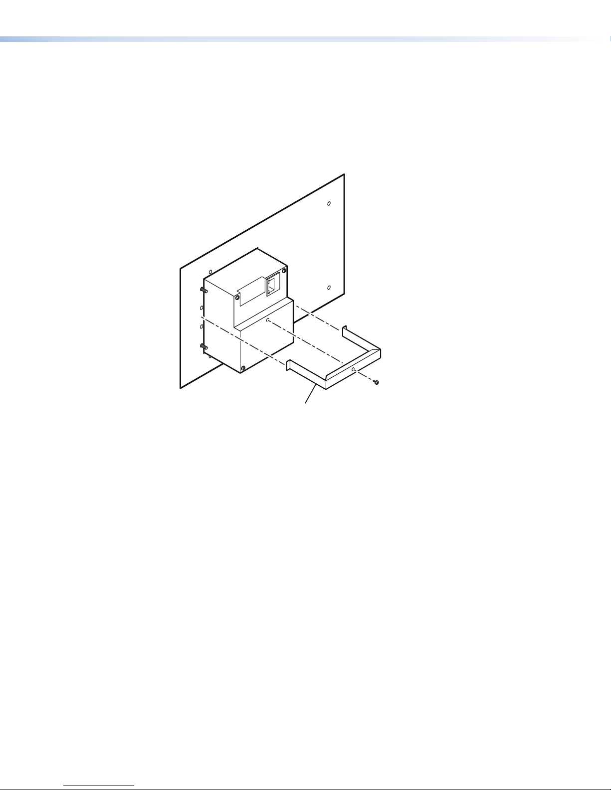
Mounting the IPI 200 Series
(included)
The IPI 201 and IPI 204 intercoms must be attached to a device faceplate or AAP wall plate and
cabled before the device or wall plate is installed in a wall or furniture. Unlike the IPI 100 Series
intercoms, the IPI 200 AAP Series intercoms are secured by attaching a clamp bracket to the
back of the intercom after it has been inserted through the front of the AAP plate.
1. Before cables are attached, insert the IPI through the front of the device faceplate or AAP
mounting frame. Secure the IPI to the faceplate/wall plate by attaching the provided clamp
bracket.
Extron
IPI 204 AAP
Intercom
(rear view)
Clamp Bracket
Figure 35. Mounting the IPI 200 Series
2. Connect cables to the IPI. See IPI Rear Panel Features and Cabling on page 6.
3. Mount the AAP mounting frame or other device to the wall, furniture, or rack panel. Follow
any special mounting instructions that came with that device.
IPI 100 and IPI 200 Series • Mounting 52
Page 61
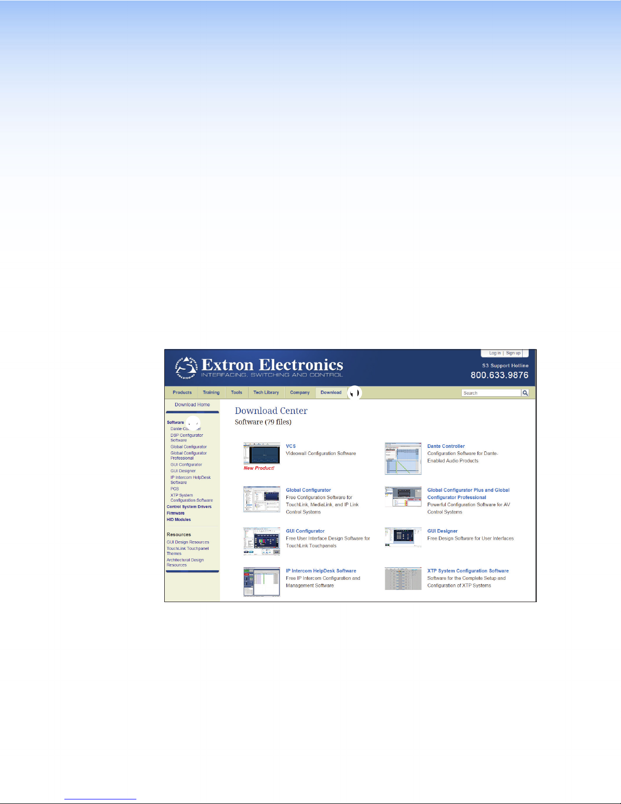
Button Labels
Installing or Replacing Button Labels
Printed labels are included with the IPI 100 Series and IPI 200 Series. In addition, users can
write on blank labels, purchase additional sheets of printed button labels from Extron (see
www.extron.com) or print their own customized button labels with the Button Label Generator
program. Replacement button caps are also available for purchase.
Button Label Generator Software
The Button Label Generator software creates labels that you can place in the translucent covers
above the buttons. You can create labels with names, alphanumeric characters, or color
graphics for easy and intuitive input and output selection.
Downloading and Installing the Button-Label Generator Software
The Extron Button Label Generator software is available at www.extron.com.
2
2
Figure 36. Download Extron Software
1. Select the Download tab (
menu bar to the left.
) at the top of the page and click the Software link (2) in the
1
11
IPI 100 and IPI 200 Series • Button Labels 53
Page 62
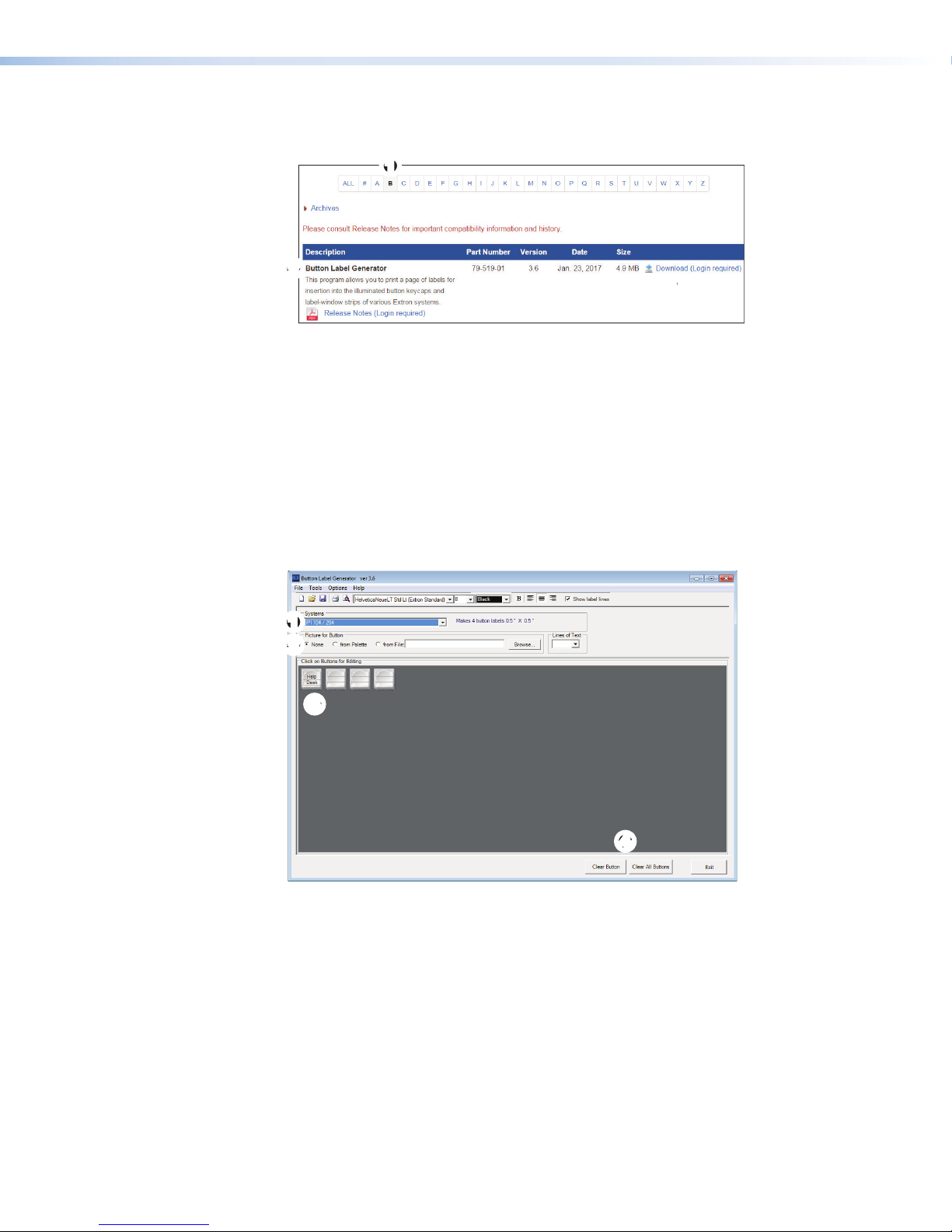
2. Scroll down to the alphabetic menu.
3. Click B (
) and scroll down to locate the Button Label Generator software (2).
1
11
2
2
Figure 37. Download Button Label Generator Software
4. Click Download (
5. Provide the requested information and follow the on screen instructions to download and
install the program.
Unless you specify a different directory, the Windows installation creates a C:\Program
Files\Extron\ButtonLabelGenerator directory and places the Button Label Generator
icon into a group or folder named Extron Electronics. A shortcut icon can also be
placed on the PC desktop.
Using the Button-Label Generator Software
1. To run the Button-Label Generator program, click on the desktop icon or open the program
from the start menu. The Button-Label Generator window opens.
3
).
3
3
11
2
2
3
3
4
4
Figure 38. Button-Label Generator Software
2. In the Systems menu (
label size and quantities for your device.
You can place text or images (2) on the button. The buttons are shown in the main panel.
3. Using standard Windows controls, you can save the buttons you have created and print
labels that can be placed in the clear button caps on the front panel of the switcher.
4. Click Clear All Buttons to create new labels as many times as necessary to make all of
the button labels that you need.
For further information, click the Help menu to open the Button Label Generator Help File.
), choose IPI 101/201 or IPI 104/204 to match the button
1
IPI 100 and IPI 200 Series • Button Labels 54
Page 63
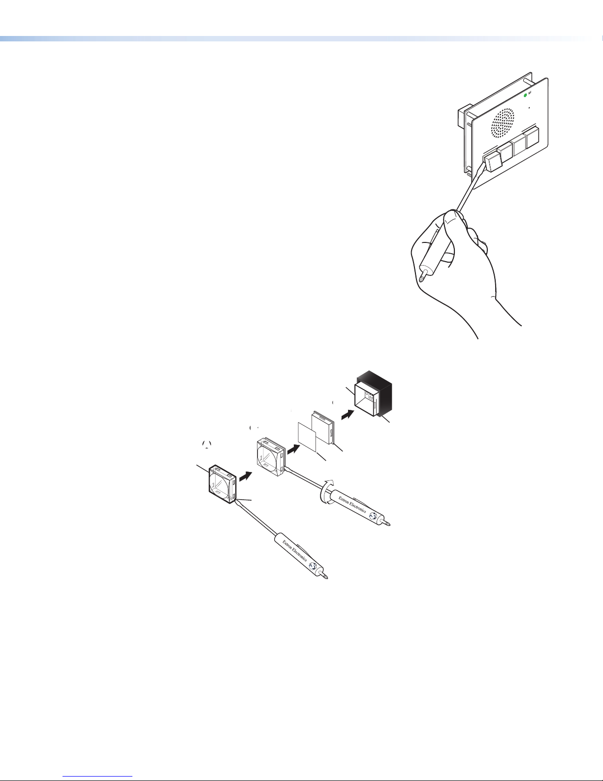
Installing Button Labels
Base
Clear Lens
The button assembly consists of a clear
lens cap, the label and a white diffuser.
To remove a button assembly and
replace a label:
1. Use a small flat-blade screwdriver
to gently pry the button assembly
away from its base (see figure 39).
2. Locate the small corner notch
on the lens cap and slide the
screwdriver between the lens cap
and the diffuser (see figure 40, A).
Using a rotating motion of the
screwdriver, carefully pry the two
pieces apart (B).
3. Replace the label with the new
button label (C).
4. Press the lens cap and diffuser
together and reinstall the button
assembly into its base (D).
5. Repeat steps 1 through 4 for each
button you plan to re-label.
INTERCOM
PUSH TO CALL
LAB
3
SECURITY
HELP
2
DESK
1
Figure 39. Remove Buttons
MIC ON
ADMIN
OFFICE
4
IPI 104
Plunger
D
C
C
B
B
TEXT
AA
Pry the two
pieces apart.
Notch
Separating the twopiece button here at
the corner.
D
Diffuser
Button Label
Figure 40. Replace Buttons
IPI 100 and IPI 200 Series • Button Labels 55
Page 64

Extron Warranty
Extron Electronics warrants this product against defects in materials and workmanship for a period of three years
from the date of purchase. In the event of malfunction during the warranty period attributable directly to faulty
workmanship and/or materials, Extron Electronics will, at its option, repair or replace said products or components,
to whatever extent it shall deem necessary to restore said product to proper operating condition, provided that it is
returned within the warranty period, with proof of purchase and description of malfunction to:
USA, Canada, South America,
and Central America:
Extron Electronics
1230 South Lewis Street
Anaheim, CA 92805
U.S.A.
Europe and Africa:
Extron Europe
Hanzeboulevard 10
3825 PH Amersfoort
The Netherlands
Japan:
Extron Electronics, Japan
Kyodo Building, 16 Ichibancho
Chiyoda-ku, Tokyo 102-0082
Japan
China:
Extron China
686 Ronghua Road
Songjiang District
Shanghai 201611
China
Asia:
Extron Electronics Asia Pte. Ltd.
135 Joo Seng Road, #04-01
PM Industrial Bldg.
Singapore 368363
Middle East:
Extron Middle East
Dubai Airport Free Zone
F13, PO Box 293666
Dubai, United Arab Emirates
Singapore
This Limited Warranty does not apply if the fault has been caused by misuse, improper handling care, electrical
or mechanical abuse, abnormal operating conditions, or if modifications were made to the product that were not
authorized by Extron.
NOTE: If a product is defective, please call Extron and ask for an Application Engineer to receive an RA (Return
Authorization) number. This will begin the repair process.
USA: 714.491.1500 or 800.633.9876 Europe: 31.33.453.4040
Asia: 65.6383.4400 Japan: 81.3.3511.7655
Units must be returned insured, with shipping charges prepaid. If not insured, you assume the risk of loss or damage
during shipment. Returned units must include the serial number and a description of the problem, as well as the
name of the person to contact in case there are any questions.
Extron Electronics makes no further warranties either expressed or implied with respect to the product and its quality,
performance, merchantability, or fitness for any particular use. In no event will Extron Electronics be liable for direct,
indirect, or consequential damages resulting from any defect in this product even if Extron Electronics has been
advised of such damage.
Please note that laws vary from state to state and country to country, and that some provisions of this warranty may
not apply to you.
Extron Headquarters
+1.800.633.9876 (Inside USA/Canada Only)
Extron USA - West Extron USA - East
+1.714.491.1500 +1.919.850.1000
+1.714.491.1517 FAX +1.919.850.1001 FAX
Extron Europe
+800.3987.6673
(Inside Europe Only)
+31.33.453.4040
+31.33.453.4050 FAX
Extron Asia
+65.6383.4400
+65.6383.4664 FAX
© 2017 Extron Electronics All rights reserved. www.extron.com
Extron Japan
+81.3.3511.7655
+81.3.3511.7656 FAX
Extron China
+86.21.3760.1568
+86.21.3760.1566 FAX
Extron Middle East
+971.4.299.1800
+971.4.299.1880 FAX
Extron Australia
+61.8.8113.6800
+61.8.8351.2511 FAX
Extron India
1800.3070.3777
(Inside India Only)
+91.80.3055.3777
+91.80.3055.3737 FAX
 Loading...