

Page 1
MBD 129 Through-Desk Mounting Kit (Part # 70-077-02)
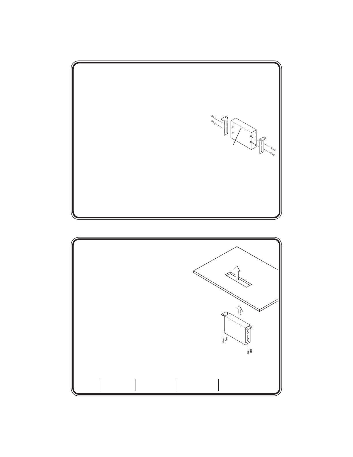
FRONT
Mounting
Screws
Housing
Screws
Extron Electronics, USA
800.633.9876 714.491.1500
FAX 714.491.1517
Extron Electronics, Europe
+800.3987.6673 +31.33.453.4040
FAX +31.33.453.4050
Extron Electronics, Asia
+800.7339.8766 +65.6383.4400
FAX +65.6383.4664
Extron Electronics, Japan
+81.3.3511.7655
FAX +81.3.3511.7656
www.extron.com
FRONT
Installation Instructions for RGB 109xi and RGB 160xi
This guide contains instructions for through-furniture mounting of only the Extron
RGB 109xi, 112xi, 160xi and 164xi interfaces using the MBD 129 kit:
1. If necessary, remove the feet from the bottom of the interface unit.
2. Remove the housing screws holding the top and bottom halves of the unit
together (two screws on each side and one screw
on the top). See the illustration to the right.
3. Slide the bottom half forwards until the back
panel is clear of the BNC connectors. Carefully
lift the top half away from the bottom half.
N
4. Align the holes in the mounting bracket with the
5. Secure the bracket to the side of the unit using the 4-40 screws and washers (four
6. Reassemble the unit by bringing the top and bottom halves together and guiding
Avoid placing strain on the power cable
between the top and bottom halves.
mounting holes in the side panel of the interface unit.
of each provided with the mounting kit) and hexagonal nuts (four provided
with the interface). The screws must hold the unit in postition but let it slide up
and down with minimal force.
the BNC connectors through the holes in the back panel. Fasten the top and
bottom halves together with the housing screws removed in step 3.
7. Mark the position where the hole will be cut in
the furniture to accommodate the unit. See the
illustration to the right.
8. Cut the hole and test that the unit moves
easily through the hole. If necessary, use a
rasp or coarse file to enlarge the hole.
9. Hold the unit, with the mounting brackets
attached, under the furniture where it will
be secured. Mark where the screws will attach
the mounting bracket to the underside of the
furniture.
10. Drill four pilot holes 3/32” (2 mm) in diameter
and 1/4” (6 mm) deep.
11. Secure the unit to the furniture with the wood
screws (four provided with the mounting kit). See
the illustration at right.
68-1480-01
Rev A
10 07
 Loading...