

Page 1
ISM SC Output Board Installation Notes
Balanced Stereo Output
Tip
Ring
Sleeve(s)
Tip
Ring
L R
Left
Right
Unbalanced Stereo Output
Tip
NO GROUND HERE.
Sleeve(s)
Tip
NO GROUND HERE.
L R
Left
Right
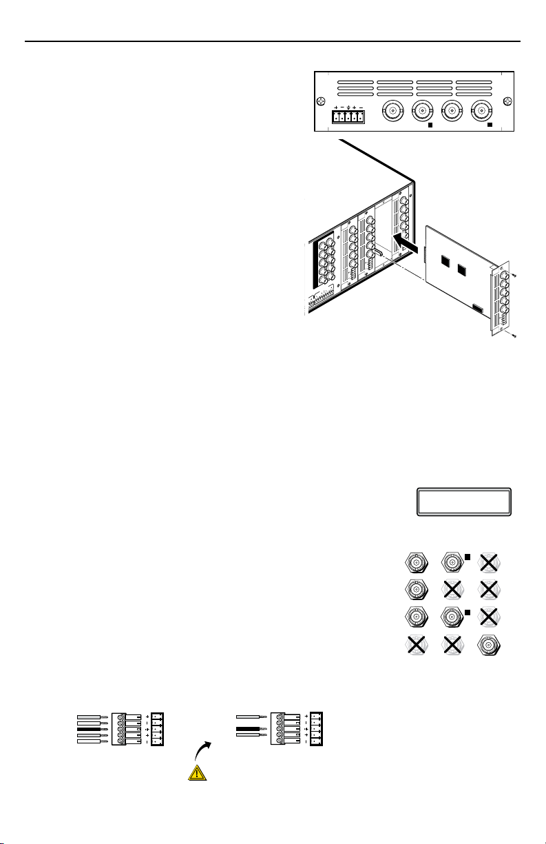
CAUTION
For unbalanced audio, connect the sleeve(s)
to the center contact ground. DO NOT connect
the sleeve(s) to the negative (-) contacts.
2
1
R/R-Y
G/Y
VID
B/C
B-Y
H/HV
V
PASS THRU
OUTPUT
VIDEO
SCALER
70-545-01
3
R/
R-Y
G/Y
B/
B-Y
H/
HV
V
OUTPUT
UNIV.
SCALER
70-544-01
5
R/
R-Y
G/Y
B/
B-Y
H/
HV
V
OUTPUT
PASS
THRU
70-547-01
8
R/
R-Y
G/Y
B/
B-Y
H/
HV
V
Extron
ISM 824
Integration Scaling
Matrix Switcher
Align output board
with top and bottom
plastic guides.
R/
R-Y
G/Y
B/
B-Y
H/
HV
V
OUTPUT
7
SCAN
CONV.
70-546-01
Example Output Board Installation
New ScanConverte
Slot #2 14
SCAN
CONVERTER
R/
R-Y
G/Y
B/
B-Y
VID
C
Y
L
R
RGsB o r
Compon ent
Video
S-Vide o Compo site
Video
VID VID
VID
R/R-Y
G/Y
B/
B-Y
R/R-Y
G/Y
B/
B-Y
R/R-Y
G/Y
B/
B-Y
C
Y
C
C
Y
Y
The Extron ISM SC is a scan converter output board for the ISM 824 with four BNC connectors
and a local audio output. The board mounts in one of
the four vertical expansion slots (numbered 1 to 4) at
the rear of the ISM 824.
For full operating details of the ISM refer to the
ISM 824 User’s Manual, online at www.extron.com.
To install an output board in the ISM 824 base unit,
1. Turn off the ISM 824, and remove the power cord.
Repeat for all connected devices.
2. At the rear, select an open slot, or take out the blank
plate from the desired output port by removing the
two retaining screws (top and bottom), and lifting
the blank away.
N Re-use the screws to secure the new output
3. Remove the board from its outer box and anti-ESD
4. With the board upright, align the front (non-connector end) of the board with the top and
board in place. Retain the blank plates.
If a board is already installed in the desired slot,
remove the screws and carefully pull out the
board.
bag, holding the board by the rear frame.
bottom plastic guides in the ISM 824. Slide the board in carefully, keeping within the guides.
Push it into place firmly, and secure it with the retained screws.
5. If applicable, repeat steps 2 through 4 for any other output boards.
6. Power on the ISM 824. The new output board(s) is autodetected, and
takes approximately 30 seconds to initialize. The 16 character LCD
display indicates the new board type, slot used, and counts down the
initialization time. See inset for example display for a new ISM SC board installed in slot #2,
with 14 seconds left.
7. Following the image at right, connect output device cables
to the BNC connectors to output RGsB, component, S-video or
composite video signals. The output can be configured from the
front panel or by SIS™ commands. The composite video output
(the bottom BNC connector) is always active.
8. Insert a 5-pole captive screw connector into the local audio output
connector for balanced or unbalanced stereo audio output.
Wire the connector as shown below.
.
1
Page 2
ISM SC Output Board Installation Notes, cont’d
Select Output
#x ScanConverter
Next
Input Setup
#x ScanConverter
Aspect Ratio
4:3
Next
Rotate either encoder
to select (4:3 or 16:9)
Next
H Start V
xxx xxx
Rotate encoder to adjust H
start and to adjust V start
Next
Total Pix Phase
xxxx xxxx
Rotate to adjust Total Pix
value and encoder to adjust
Phase value
Next
H Active V
xxxx xxxx
Rotate to adjust H active
value and encoder to adjust
V active value
Menu
Next
Output Config
Next
Next
Rotate either encoder
to select standard
Next
Menu
User Presets
#x ScanConverter
<NA> 1 2 3
Save Preset
Next
Rotate either encoder
to select a preset to
save current settings
<NA> 1 2 3
Erase Preset
Next
Rotate either encoder
to select a preset
to erase
Advanced Config
#x ScanConverter
Next
Menu
Next
Next
Rotate encoder to select
input and encoder to turn
On or Off
Input #x Off
Auto Image
Next
None
Test Pattern
Rotate either encoder
to select a test pattern
Off <On>
Next
Auto Memories
Rotate either encoder
to turn auto memories
On or Off
#x ScanConverter
YUV
Output Type
Rotate either encoder
to select format
NTSC
Output Standard
Next
x
Flicker Filter
Rotate either encoder
to set a value
Next
x
Encoder Filter
Rotate either encoder
to set a value
Menu
Input #x <Off>
Next
Full Screen
Rotate to select input # and
to turn full screen on or off
MENU NEXT
ADJUST
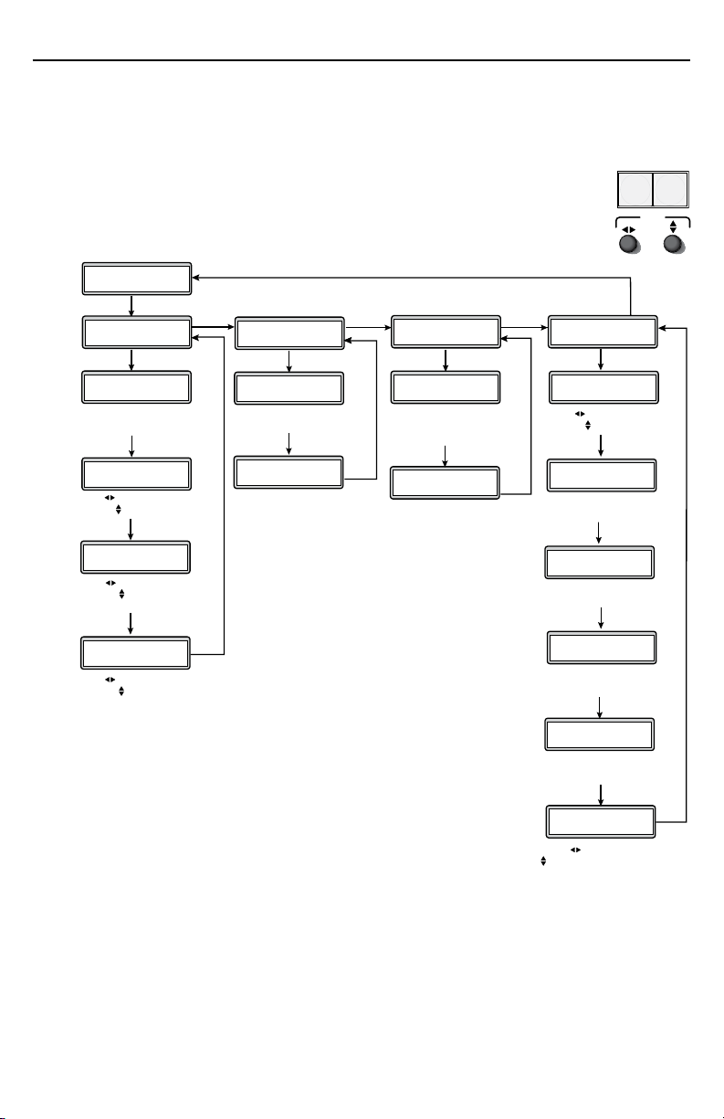
ISM SC configuration menu
Using the front panel menu buttons (Menu and Next), the ISM SC board configuration menu
can be accessed. From the Output Configuration screen, press Next until reaching the #x
ScanConverter menu (see the image below). Press Menu and Next to navigate through the
menus and use the front panel adjustment knobs ({ [), to change the settings as desired.
For full menu details see the ISM 824 User’s Manual, online at www.extron.com.
From the default cycle press Menu repeatedly to reach the Output Configuration
menu. Press Next (enters Select Output menu) and rotate either adjust knob to
select the Scan Converter menu. Follow the figure below to enter each menu and
use the Adjust knobs to change value as desired.
Input Setup
The Input Setup submenu allows configuration of aspect ratios.
horizontal and vertical start points, total pixels and phase value,
and the active horizontal and vertical area. Rotate one or both
Adjust knobs as required to change values.
Output Type
The Output Type submenu displays and allows changing the
format of the scan converted output. Use the Adjust knobs to
select RGsB, low resolution component video (YUV), or S-video.
Output Standard
The Output Standard submenu displays and allows changes to the output standard. Use the
Adjust knobs to select between NTSC, NTSC 0 IRE, and PAL.
Flicker Filter
The Flicker Filter reduces the flicker in the connected output display. When this submenu is
active, rotate either Adjust knob to set the flicker filter value (0-3).
Encoder Filter
The Encoder Filter maintains the sharpness of the connected output display. When this
submenu is active, rotate either Adjust knob to set the encoder filter value (0-3).
2
Page 3
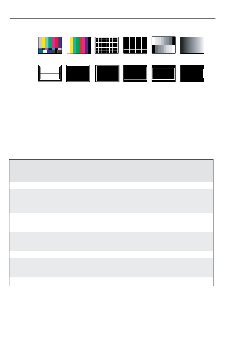
NTSC/PAL Color Bars
Grayscale
4x4
Crosshatch
32x24
Crosshatch
1.78 Crop
1.85 Crop 2.35 Crop
1.33 Crop
Crop
Ramp
Safe Area
Test pattern
The test pattern submenu offers the following test patterns to choose from:
Full Screen
The Full Screen submenu allows per-input setting of the displayed image on the output screen.
When set to Off (default) the aspect ratio follows input resolution and the output image retains
the input setting. When set to On, the aspect ratio follows the output resolution, and the
displayed image always fills the screen.
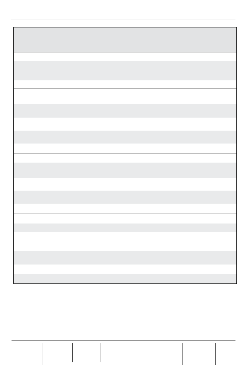
Board-specific SIS commands table
Alternatively, the ISM SC board can be configured with specific SIS commands.
The table below lists some of the ISM SC board-specific commands. For a full list of SIS
commands refer to the ISM 824 User’s Manual, online at www.extron.com.
Command ASCII
command
(host to
Response
(switcher to
host)
switcher)
Input selection
Video and
audio
Example
Video X!*X@& OutX@•InX!•RGB
Example
Audio X!*X@$ OutX@•InX!•Aud
Example
X!*X@! OutX@•InX!•All
4*2! Out2•In4•All
5*2& Out2•In5•RGB
5*2$ Out7•In3•Aud
Video output type
Set video
output type
to X\
View 36*X@#
N
36*X@*X\# X@TpoX\
SIS command table continues on page 4.
X! = Input number, 0-8
X@
= Output number, 0-8
X\
]
]
]
]
]
]
]
]
Additional description
Select video and audio input X! to
output X@.
Input 4 video and audio selected
to output 2.
Select video input X! to output X@.
Input 5 video only selected to
output 2.
Select audio input X! to output X@.
Input 3 audio only selected to
output 7.
Select video output format to X\
Where X\ = 0 = S-video, 1 = YUV,
2 = RGsB.
View the video output format.
3
Page 4
Extron USA - West
Headquarters
+800.633.9876
Inside USA / Canada Only
+1.714.491.1500
+1.714.491.1517 FAX
Extron USA - East
+800.633.9876
Inside USA / Canada Only
+1.919.863.1794
+1.919.863.1797 FAX
Extron Europe
+800.3987.6673
Inside Europe Only
+31.33.453.4040
+31.33.453.4 050 FAX
Extron Asia
+800.7339.8766
Inside Asia Only
+65.6383.4400
+65.6383.4664 FAX
Extron Japan
+81.3.3511.7655
+81.3.3511.7656 FAX
Extron China
+400.883.1568
Inside China Only
+86.21.3760.1568
+86.21.3760.1566 FAX
Extron Middle East
+971.4.2991800
+971.4.2991880 FAX
ISM SC Output Board Installation Notes, cont’d
Command ASCII
command
(host to
switcher)
Video output standard
Set video
output
standard to X\
View 37*X@#
37*X@*X\# X@Std X\
Flicker filter
Command is case sensitive
N
Set flicker
X@*X4$d X@DvzX4$
filter level
Increment
X@+d X@DvzX4$
value
Decrement
X@-d X@DvzX4$
value
View X@d
Encoder filter
Set encoder
filter level
Increment
value
Decrement
value
View 24*X@#
24*X@*X4$# X@EncX4$
24*X@+# X@EncX4$
24*X@-# X@EncX4$
Response
(switcher to
host)
]
X\
]
]
]
]
X4$
]
]
]
]
X4$
]
Additional description
Set video output standard to X\
Where X\ is: 0 = NTSC,
1 = NTSC 0 IRE, 2 = PAL.
View the video output standard.
Specify the flicker filter level to
X4$.
Increase the flicker filter level.
Decrease the flicker filter level.
View the flicker filter level.
Set encoder filter level to X4$
Increase the flicker filter level.
Decrease the flicker filter level.
View the encoder filter level.
.
Test pattern
On X@*X2) J TstX@*X2)
View X@ J
Full screen
Enable 99*X@*X!*1# X@FulX!*1
Disable 99*X@*X!*0# X@FulX!*0
View 99*X@*X!#
N
4
Select test pattern.
View the test pattern selection.
Output full screen for selected
X2)
]
]
]
input.
Turn full screen off.
View the current on/off status.
X2(
]
]
X! = Input number, 0-8
X@ = Output number, 1-8
X2)
= Test pattern, 00 = off, 01 = color bars, 02 = 32x24 crosshatch, 03 = 4x4 crosshatch,
04 = gray scale, 05 = ramp, 06 = safe area, 07 = crop, 08 = 1.33 crop, 09 = 1.78 crop,
10 = 1.85 crop, 11 = 2.35 crop
X2(
= Mode status, 1 = on, 0 = off
X4$
= Filter value, 0-3
© 2009 Extron Electronics. All rights reserved.
68-1123-61
Rev A
04 09
 Loading...