

Page 1
IMPORTANT:
Go to www.extron.com for the complete
user guide, installation instructions, and
specifications before connecting the
IPCP Pro Series • Setup Guide
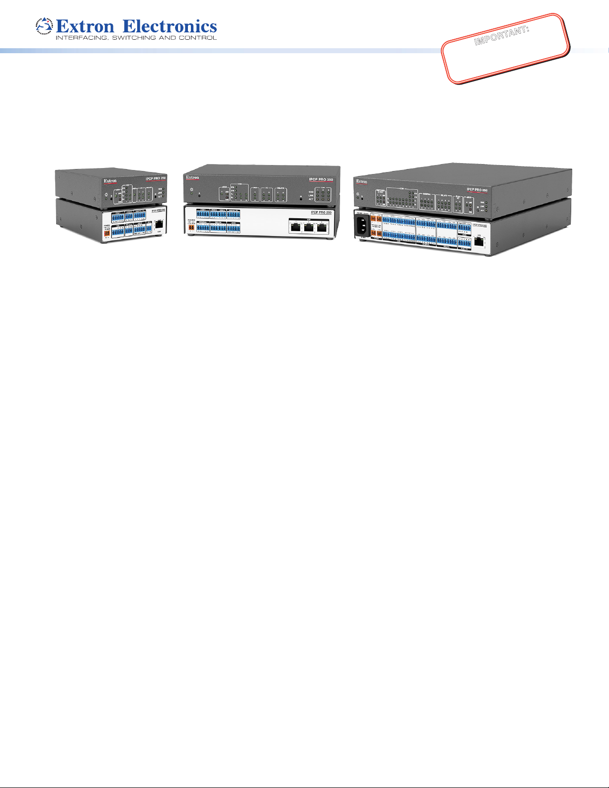
The Extron IPCPPro Series IPLink® Pro Control Processors integrate Ethernet connection into AV systems to allow users to
remotely control, monitor, and troubleshoot AV equipment, including display devices and switchers. These control processors
include an embedded web server. Depending on the model, an IPCPPro control processor can include multiple bidirectional
serial ports, relays, IR/serial ports, digital I/O, flex I/O, switched 12 VDC power output ports, a volume control port, or contact
input ports for use in applications that require control and monitoring of multiple devices within a large-scale AV system.
This guide provides instructions for an experienced installer to install an IPCPPro Series control processor and to create a
basic configuration. Configure the control processor using Extron Global Configurator software running in Global Configurator
Professional (GCProfessional) or Global Configurator Plus (GC Plus) mode. The IPCP integrates seamlessly with Extron
GlobalViewer® Enterprise (GVE) software and the GlobalViewer web-based AV resource management for remote control
applications. These control processors support multiple TouchLink®Pro touchpanel interfaces over a standard Ethernet network.
Global Configurator and other useful software applications are available at www.extron.com.
product to the power source.
Setup Checklist: How to Proceed With Installation
Get Ready
Familiarize yourself with the features of the control processor (see Front Panel Features on page3 and Rear Panel
Features on page4) and of any TouchlinkPro touchpanels that will be part of the system.
Download and install the latest version of the following:
• Global Configurator (GC) software — for setting up and configuring the control processor. GCProfessional and
GCPlus modes include the Toolbelt feature, IR LearnerPro (for creating IR driver files using the remote controls of AV
products if drivers are not already available from Extron), and a way to upgrade the firmware of the control processor if
the need arises.
• IPLinkPro device drivers — for use with GC, to make control of other devices possible
• GUI Designer software — for designing layouts for Extron TouchlinkPro touchpanels and third party touch interfaces
All are avail able from www.extron.com (see Locating Software, Firmware, and Driver Files on the Extron Website on
page9).
Obtain network information for the unit from the network administrator. You will need the following details for each IPLinkPro
device:
DHCP setting (on or off) Subnet mask User name
Device (IPCP Pro, TouchlinkPro, IPLPro) IP address Gateway IP address Passwords
Write down the MAC addresses of each IPLinkPro device to be used.
Obtain model names and setup information for devices the IPCP will control.
Mount and Cable All Devices
Mount the unit to a rack or furniture (see Mounting on page2).
Cable devices to the control processor (see Cabling and Features on page 5).
Connect power cords and power on all the devices.
Set Up the Control Processor and Touchpanels for Network Communication
Connect the PC that you will use for setup, the control processor, and touchpanels to the same Ethernet subnetwork.
For control processor LAN connections, see Control, Bidirectional — LAN (Ethernet) on page6.
Start Global Configurator and use the Toolbelt feature of the software to set the IP address, subnet, gateway IP address,
DHCP status, and related settings. See the flowchart in Network Communication Setup on page2.
1
Page 2
IPCP Pro Series • Setup Guide (Continued)
Configure the Control Processor and Touchpanels
The most basic steps are outlined below in the recommended order.
NOTE: See the Global Configurator Help file and GUI Designer Help file as needed for step-by-step instructions and detailed
information. The help file for GC includes an introduction to the software and how to start a project and configuration.
If TouchlinkPro touchpanels will be part of the system, start and use GUI Designer to design, save, and build the graphical
user interface (GUI) layout for the touchpanels. See the GUIDesigner Help file for instructions.
Using GC, create a new GCPro or GCPlus project and configure the control processor and other IP Link Pro devices.
The configuration tells the control processor how its ports will function; how to control other products; which touchpanels to
interact with; what to monitor; when to do things; and whom to notify, how, and under what circumstances.
Configure ports on the control processor.
• Select device drivers and link them to each serial, IR/serial, or Ethernet port.
• Select settings (serial protocol, relay behavior, digital I/O or flex I/O settings) as needed.
Set up monitors, schedules, macros, and local variables.
Add touchpanels and set them up:
• Upload the GUI configuration to the touchpanels using Global Configurator.
• Assign any appropriate functions, monitors, or schedules to the touchpanels and their buttons.
Save and build the project.
Upload the system configuration to the control processor.
Test and Troubleshoot
Test the system. See the IPCPProUser Guide for an outline
of the system testing procedure.
Make adjustments to wiring or configuration as needed.
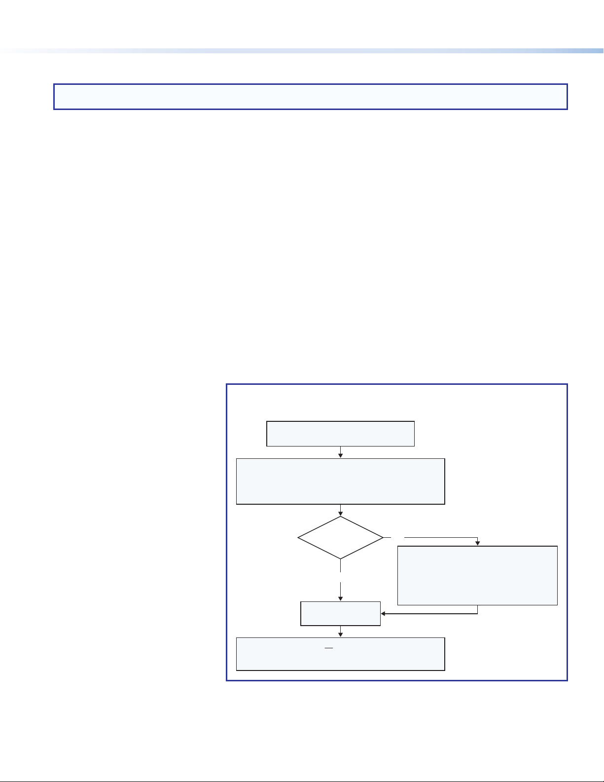
Network Communication Setup
Network setup is essential prior to
configuration. Use the flowchart as a
guide to setting up the control
processor for network use.
Network Communication Setup,
Connected/Online Method
Connect the control processor and PC
to the same LAN and apply power.
Global Congurator (GC Professional or GC Plus mode).
ToolBelt displays a list of all IP Link Pro devices
then congure other network settings as needed.
Open the Toolbelt utility in
connected to the network.
Do you
know the MAC
address?
Yes
Select the desired
device from the list.
Enable DHCP or you must type in the
IP address, subnet address, and gateway,
No
device in the list and observe the device. The
front panel LEDs of the selected device ash.
Activate the Identify Hardware feature.
To determine the correct device, click on a
Click on devices in the list until the LEDs
of the correct device ash.
Figure 1. Network Setup, Online Method
Mounting
Securely mount the control processor and other devices and attach cables using the wiring section (Cabling and Features on
page5) as a wiring guide. Optional 1U rack shelves and furniture mounting bracket kits are available for use with the
control processor. Read the instructions and UL guidelines that come with the rack shelf or mounting kit for installation procedures.
See the product-specific page at www.extron.com for a list of compatible accessories for mounting your control processor.
2
Page 3
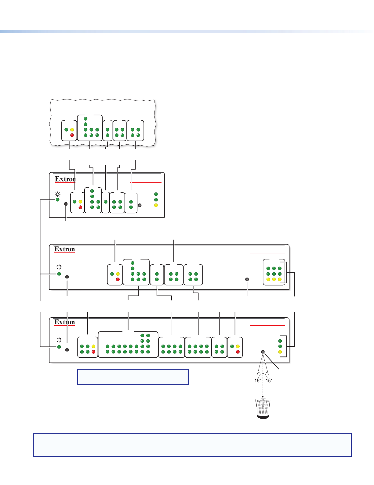
Panels and Locations of Features
Power
IPCP Pro 350M
Location and quantity of LEDs and corresponding connectors vary by model, but the functions and port wiring are identical
across models for each port type.
Front Panel Features
(within another device)
COM
RTS
eBUS
S
LIMIT
OVER
eBUS
LEDs
R
eBUS
S
CTS
Tx
Rx
COM
(Serial)
LEDs
RTS
CTS
LIMIT
Tx
Rx
OVER
COM
1
IR/S
2231
IR/
Serial
LEDs
IR/S
2
I/O
3142314
Flex
I/O
LEDs
I/O RELAYS
2
314
RELAYS
21
Relay
LEDs
IPCP PRO 250
1000
1
LINK
IR
ACT
2
LED
Reset Button
(recessed)
R
Switched
Reset
Button
(recessed)
R
eBUS LEDs
RTS
eBUS
CTS
S
LIMIT
Tx
Rx
OVER
12 VDC
LEDs
SWITCHED
12 VDC
21
LIMIT
43 12345678
OVER
COM (Serial)
LEDs
COM
Tx
Rx
COM
Digital I/O LEDs
I/O
IR/S
2231
2
314
IR/Serial
LEDs
RTS
IR/SERIAL RELAYS FLEX
CTS
2134
Tx
Rx
5 678
NOTE: Numbers adjacent to LEDs correspond
to the like-numbered rear panel ports.
RELAYS
21
314
Relay
LEDs
5 678213 4
Flex I/O
LEDs
I/O
2134
IPCP PRO 350
IR
IR Receiver
eBUS LEDs
IPCP PRO 550
eBUS
S LIMIT
OVER
1000
LINK
ACT
12
1000
LINK
IR
ACT
2–12"
(4–30 cm)
LAN
3
LAN/
Network
LEDs
IR Receiver
IR Learning Angle
and Distance
Figure 2. IPCP Pro Series Front Panel Features
1 2 3
4 5 6
7 809
NOTES:
• For reset mode information, see the IPCPProSeries User Guide.
• The Reset button and power LED for the IPCPPro350M are located next to the rear panel connectors.
3
Page 4

IPCP Pro Series • Setup Guide (Continued)
analog input) ports
RS-485 ports
ports
output ports
power supply)
connector (exter
Power
Rear Panel Features
LED
IPCP Pro 350M
(within another
device)
COM 1
IR/SERIAL
1SG2
R
Reset
button
(recessed)
IR/serial
output
ports
5-pole COM
RS-232/RS-422/
RS-485 ports
IPCP Pro 350
POWER
12V
1.0A MAX
GTx Rx
RTSCTS
SG
COM 1
GTx Rx
RTSCTS
IR/SERIAL
1SG2
COM 2COM 3
GTx Rx GTx Rx
RELAYS
2143CC
Relay
ports
3-pole COM
RS-232- only
COM 2 COM 3
RELAYS
2143CC
SG
ports
GTx Rx GTx Rx
DIGITAL I/O
1234G
eBUS
+V +S -S G
PWR OUT = 6W
eBUS
accessory
ports
Digital I/O
(digital input/
output) ports
DIGITAL I/O
1 234G
eBUS
+V +S -S G
PWR OUT = 6W
1
23
LAN
(Ethernet)
connectors
and LEDs
5-pole COM
RS-232/RS-422/
RS-485 port
COM 1
Tx Rx
POWER
12V
X.XA MAX
VOL
Power input
connector
(external
power supply)
00-05-A6-XX-XX-XX
MAC: 00-05-A6-XX-XX-XX
S/N: ####### E######
3-pole COM
RS-232-only
ports
COM 2
G
RTSCTS
Tx Rx
RELAYS
VCG
Volume
control
port
123
G
C12
DIGITAL I/O
12 4G
PWR OUT = 6W
Digital I/O
(digital input/
output) ports
IPCP Pro 250
3
eBUS
IR/S
-S+V +S G
SG
IPCP PRO 350
LAN
IPCP PRO 250
MAC: 00-05-A6-XX-XX-XX
S/N: ####### E######
LAN
Power input
nal
power supply)
IPCP Pro 550
100-240V ~ 50-60Hz
1.2A MAX
Power input
connector (internal
1 1 2 3 7
2 1 2
SWITCHED 12 VDC
40W MAX TOTAL
Switched
12 VDC power
TxRx GTxRxG TxRx GTxRxG SGSG SGSG
3 4
4 5 6
TxRx GTxRxG TxRx GTxRxG
3-pole COM
RS-232-only
5-pole COM
RS-232/RS-422/
Figure 3. IPCP Pro Series Rear Panel Features
RTSCTS
8
RTSCTS
ports
3 4
5 6
7 8
SGSG SGSG
Relay portsIR/serial output
1 2
5 6
eBUS
accessory
ports
PWR OUT = 12W
3 4
+V +S -S G
eBUS
7 83214G
FLEX I/ORELAYSIR/SERIALCOM12 VDC
Flex I/O
(digital input/output or
LAN
(Ethernet)
connectors
and LEDs
IPCP PRO 550
LAN
00-05-A6-XX-XX-XX
MAC: 00-05-A6-XX-XX-XX
S/N: ####### E######
MAC
address
4
Page 5

Cabling and Features
Smooth
Rear Panel
Front Panel
f for
Attach cables using the following wiring diagrams as a guide. Full details are available in the IPCPPro Series User Guide.
ATTENTION: Installation and service mus t be performed by experienced personnel.
ATTENTION: L’installation et l’entretien doivent être effectués par du personnel expérimenté.
Power Input — External
POWER
12V
x.xA MAX
Rear
Panel
Tie Wrap
Ridged
3/16"
(5 mm)
Max.
Power Input, External Power Supply
• Connect to
included 12 VDC
power supply.
+12 VDC input
Power Input — Internal
100-240V 50-60Hz
Power Input, Internal Power Supply
• Connect to 100 to
240 VAC.
1.2A MAX
– Return
• Front panel LED ( ) blinks during
boot-up and lights when the IPCP
is powered and operational.
Ridged
Smooth
1A MAX
100-240V 50-60Hz
External
Power Supply
• Front panel LED ( ) blinks
during boot-up and lights
when the IPCP receives power.
Ground
all devices.
R
Front Panel
NOTE:
Check the polarity of
the power supply before
connecting it to the IPCP.
R
ATTENTION:
Always use a power supply
supplied or specified by Extron.
Use of an unauthorized power
supply voids all regulatory
compliance certification and
may cause damage to the
supply and the unit.
ATTENTION:
Utilisez toujours une source
d’alimentation fournie par Extron.
L’utilisation d’une source
d’alimentation non autorisée
annule toute conformité
réglementaire et peut
endommager la source
d’alimentation ainsi que l’unité.
Power Output — Switched 12 VDC Power Output
1 2
SWITCHED 12 VDC
40W MAX TOTAL
3 4
Rear
Panel
12 VDC
3/16"
(5 mm)
Max.
Tie Wrap
Switched 12 VDC
Power Output
• 12 VDC, 40 watts (max.)
= total output for all four ports
combined
• Corresponding front panel
green LEDs ( ) light when
power is available at each port.
Front
Panel
SWITCHED
12 VDC
21
43
Lights if total power draw
LIMIT
is 44-48 watts.
OVER
Lights if total power draw
exceeds 48 watts.
Power output shuts of
a period to allow the user
to correct the overload.
5
Page 6

IPCP Pro Series • Setup Guide (Continued)
RELAY
2
1
C
SGS
G
Rear
eceived.
PC
Control, Bidirectional — Serial (COM)
Panels
(RS-232)
Serial (COM) Ports
Select protocol via software.
COM port default protocol:
• 9600 baud
• 8 data bits • 1 stop bit
• no parity • no ow control
COM 2
GTx Rx
1 7
TxRx GTxRxG
or or
4
TxRx GTxRxG
COM 1
GTx Rx
IR/SERIAL
RTSCTS
8
RTS
RTSCTS
CTS
5-pole COM
(RS-232, RS-422, RS-485)
NOTE: The 5-pole COM ports support both
3-pole COM
hardware and software ow control.
The 3-pole COM ports support software
ow control only.
To 5-pole
COM port
To 3-pole
COM port
Heat Shrink
Over Shield Wires
CTS
RTS
G Ground
Rx Receive
Tx
G
Ground
Rx
Receive
Tx
Transmit
Request to send
Transmit
Heat Shrink
Transmit (Tx)
Receive (Rx)
Strip wires 3/16"
(5 mm) max.
Transmit (Tx)
Receive (Rx)
Projector, Panel
Display, PC, or Other
RS-232, RS-422, or
RS-485 Device
RS-232-
Controllable
Device
Clear to send
NOTE: If you use cable that has a drain wire, tie the drain wire to ground at both ends.
Front Panels
COM
Tx
Rx
12345678
RTS =
Request to Send
CTS = Clear to Send
Tx = Transmitting Data
Rx = Receiving Data
RTS
CTS
Tx
Rx
5-pole COM Pin Configurations
RS-232
Tx
Rx
Ground
RTS
CTS
RS-422
Tx-
Rx-
Ground
Tx+
Rx+
(pins 1 & 2
tied together)
(pins 4 & 5
tied together)
Pin
1 (Tx)
2 (Rx)
3 (G)
4 (RTS)
5 (CTS)
RTS
CTS
Tx
Rx
COM
231
RS-485
Data-
Ground
Data+
Control, Bidirectional — LAN (Ethernet)
TCP/IP
Insert Twisted
RJ-45
Connector
Rear Panel
12
Network
Ethernet
Pair Wires
Pins:
LAN
12345678
or
Activity
LED
Touchlink Pro
Touchpanel
Straight-through Cable
(for connection to a switch, hub, or router)
End 1 End 2
Pin Wire Color Pin Wire Color
1 white-orange 1 white-orange
2 orange 2 orange
3 white-green 3 white-green
4 blue 4 blue
5 white-blue 5 white-blue
6 green 6 green
7 white-brown 7 white-brown
8 brown 8 brown
LAN
Link
LED
NOTE: IPCPs with more than one LAN or LAN A port function
Extron Devices
(Switchers, Scalers)
Crossover Cable
(for direct connection to a PC)
End 1 End 2
Pin Wire Color Pin Wire Color
1 white-orange 1 white-green
2 orange 2 green
3 white-green 3 white-orange
4 blue 4 blue
5 white-blue 5 white-blue
6 green 6 orange
7 white-brown 7 white-brown
8 brown 8 brown
T568B T568AT568BTIA/EIA-T568B
LAN (Ethernet)
Default protocol, public ports:
• IPCP IP address: 192.168.254.250
• Gateway IP address: 0.0.0.0
• Subnet mask: 255.255.255.0
• DNS address: 127.0.0.1
• DHCP: off • DNS: 127.0.0.1
• Link speed and duplex level: autodetected
• Data rates: 10/100/1000Base-T
Default login
credentials:
• Username:
admin
• Password:
extron
as multiport, unmanaged network switches so you can
connect additional devices to the same network.
• Use a straight-
through cable for
connection to a
switch, hub, or router.
• Use a crossover
cable for connection
directly to a PC. Wire
the connector as
shown in these tables.
Front Panel
LAN
123
1000
LINK
ACT
1000 Mbps
Connection
Network is
active.
Data is being
sent/r
The control processor is assigned a unique user hardware ID number (MAC address) (for example,
00-05-A6-05-1C-A0). You may need this address during configuration of the control processor. A
label that indicates the MAC address is located on the rear panel of the unit.
6
00-05-A6-XX-XX-XX
MAC: 00-05-A6-XX-XX-XX
S/N: ####### E######
MAC: 00-05-A6-XX-XX-XX
S/N: ####### E######
MAC
Address
Page 7

Control, Unidirectional — IR/Serial
Two Single IR Emitters
Source Device
Relay 1
Rear Panels Front Panels
1 2
or or
SGSG SGSG
To a Projector,
Panel Display, or the
Wired IR Remote or
RS-232 Port of a
IR/SERIAL
1SG2
SG
IR or RS-232
Output
Ground
5 6
SGSG SGSG
IR/SERIAL
Control, Unidirectional — Relays
All relays
are
normally
open.
Open (2)
Normally
Common
3 4
7 8
or
Unidirectional
IR
Output options:
• IR (30 kHz to 300 kHz,
• Unidirectional RS-232
Ground
G
IR Output Signal
S
IR/Serial Ports
with or without carrier signals)
(-)
(+)
(-)
(-)
(+)
(+)
IR/S
1
2
IR/Serial LEDs
Light when signals are transmitted
on the corresponding IR/serial port.
To the IR Receiver of a
Projector, Display, or
Source Device
IR/SERIAL
2134
5678
Rear Panels
1 2
5 6
RELAYS
3 4
7 8
To Room
Control
Equipment
or
Open (1)
Normally
RELAYS
2143CC
Common
Common
Relay 2
• Connect devices for relay control.
Relays
• Do not exceed a total of 24V at 1A for each port.
To Room
Control
Equipment
Normally
Open
Closed
1 2
Front Panel
RELAYS
2134
5678
Relay LEDs
Light when the corresponding
relays are activated (tied to GND).
7
Page 8

IPCP Pro Series • Setup Guide (Continued)
Device 1
1
Control, Unidirectional — Flex I/O or Digital I/O
Rear Panel Front Panel
DIGITAL I/O
1 234G
3214G
FLEX I/O
Heat
Shrink
Over
Shield
Wires
Ground
Wire
Nut
Device 4
G
4
3
2
Switch,
Sensor
Device 3
Device 2
Digital I/O (digital input/output)
Congure each port as as a digital input or output,
with or without +5 VDC pull-up.
Use these ports to:
• Monitor or trigger events and functions (toggle relays,
issue commands, send e-mail), once congured.
• Power LEDs, incandescent lights, or other devices
that accept a TTL signal.
Flex I/O (digital input/output or analog input)
Congure each port as an analog input or as a digital
input or output with or without +5 VDC pull-up.
Share the same ground among
I/O connections.
(Switches, sensors,
LEDs, relays, or
similar items)
I/O
2
314
FLEX
I/O
21
34
Digital I/O
LEDs
Light when the
corresponding
ports are active.
Flex I/O LEDs
Light when the
corresponding
ports are active.
Control — Volume
Rear Panel
VOL
VCG
G
Ground (Gnd)
C
Control voltage (variable output to amp from IPCP Pro) – This signal controls the amp volume.
V
Reference voltage input (from amplier) – This allows the IPCP Pro to detect when the amp is present.
Example:
Connecting to
Extron Amplifiers
IPCP Pro
Rear
Panel
Reference
voltage: ≤10 VDC
VCG
Control voltage output:
0 - 10 VDC
This port can be used to control the volume and mute or
Volume Control
unmute the audio for Extron half rack width audio ampliers.
• Connect to an Extron audio ampier to permit volume
control via touchpanel controls, macros, or schedules.
• Do not exceed 10 VDC input voltage.
Congure the maximum and minimum voltage limits. Set
Soft Start mode off or on (default) . Soft Start mode allows
volume to gradually increase from mute to the previous level
after muting or power-on to prevent loud audio bursts
XPA 1002
10V 50mA
GCV
MPA 401 Series
G
STANDBY
REMOTE
10V 50mA
10V 50mA
MPA 181T,
MP 101 Series
REMOTE
10V
VOL/MUTE
GCV
MPA 152MPA 152 Plus
REMOTE
GCV
V or 10V G or
C or
VOL/MUTE
10V 50mA
VOL/MUTE
NOTE:
Use shielded cable and
place the control processor
as close as possible to the
amplier to avoid picking up
background noise via the
cable. Ideal cable length is
six feet or less.
NOTE: When audio mute is active, the
control processor sets output voltage
0 VDC, even if the voltage range
to
(minimum and maximum voltage
limits) has been set to levels above
zero, such as 2 V to 8 V.
G
Ground
C
Control voltage
V
Reference voltage
8
Page 9

About Global Configurator (with GCProfessional and GC Plus Modes)
What The Software Does
Global Configurator is the software tool for network setup and configuration of an IPCPPro control processor. Global
Configurator:
• Loads device drivers for monitoring the status of and controlling devices within the AV system.
• Uploads GUIDesigner layouts to touchpanels and third party touch interfaces.
• Creates the configuration containing all the settings for the control processor and the products with which it interacts in the
AV system.
• Generates a graphical user interface called GlobalViewer that is uploaded to the control processor (a GlobalViewer host
device) along with the completed configuration and can be accessed as a web page.
Using GlobalViewer, users can monitor and control Extron and third-party equipment such as projectors, displays, computer
monitors, VCRs, and DVD players.
Resources
Obtaining Control Drivers
Extron provides an extensive selection of device drivers available on the
Extron website. If the system requires a control driver that is not already
available, you have additional options:
• Request a new serial (RS-232) or Ethernet driver from Extron.
• Create your own custom IR device driver using Extron IRLearner
software. Follow the directions in the IRLearner Help file to create
a driver by using the remote control for that device and the IR
receiver port on the front panel of the IPCPPro.
Obtaining Instructions, Information, and Assistance
A checklist of basic setup steps is provided at the
beginning of this guide. For additional information
see the help files and the IPCPProSeries User
Guide, available at www.extron.com.
If you have questions during installation and
setup, call the ExtronS3 Sales & Technical
Support Hotline or the ExtronS3 Control
Systems Support Hotline.
Locating Software, Firmware, and Driver Files on the Extron Website
There are three main ways to find software, firmware, and device drivers within www.extron.com:
• Via links from the web page for the specific product
• Via the Download Center page (Click on the Download tab at the top of any page within www.extron.com.)
• Via links from search results
NOTE: For some software you have the option to click the Download Now button to begin downloading the software file.
For other software there is a link for contacting an Extron support representative who can provide you access to the latest
version.
To obtain Global Configurator (GCProfessionalfessional, GC Plus) software, you must have an Extron Insider account and
contact an Extron support representative. Extron provides training to our customers on how to use the software. Access to
Global Configurator Professional is available to users who successfully complete Extron Control Professional Certification.
NOTE: New RS-232 and Ethernet drivers are required. You must use serial and Ethernet drivers developed specifically
for the IPLinkPro platform. With the exception of IR device drivers, drivers used for the previous generation
IPLink (non-Pro) control processors are not compatible.
9
Page 10

IPCP Pro Series • Setup Guide (Continued)
Overall Configuration Procedure for the Control Processor
Within Global Configurator
(GC Professional or
GC Plus mode):
Configure the IP settings of
the control processor and the
TouchLink Pro touchpanels.
Create a new GC Professional or GC Plus project
and add the control processor to it.
Will
TouchLink Pro or
No Yes
third party touchpanels or
other user interfaces
be used?
Create GUI layouts for the
touchpanels or other interfaces:
1. Start GUI Designer.
2. Create GUI layout designs for each
TouchLink Pro or third party
touchpanel (with a TouchLink
Interface), or for a computer or
mobile device (with LinkLicense).
3. Save and build the GUI layout le.
Congure ports on the
control processor.
Create monitors, schedules,
macros, and local variables.
“Network
See “Network
Communication
Communication
Setup”
Setup” in this
guide.
Import GUI layouts, add touchpanels
or other interfaces (if used), and
congure them.
Save the project.
Build and upload the conguration to
the control processor.
Test the system, make adjustments,
nalize conguration.
Figure 4. Overall Configuration Steps
If you have questions during installation and setup, you can call the Extron S3 Sales & Technical Support Hotline
or the Extron S3 Control Systems Support Hotline (1.800.633.9877).
Extron Headquarters
+1.800.633.9876 (Inside USA/Canada Only)
Extron USA - West Extron USA - East
+1.714.491.1500 +1.919.850.1000
+1.714.491.1517 FAX +1.919.850.1001 FAX
10
© 2014 Extron Electronics All rights reserved. All trademarks mentioned are the property of their respective owners. www.extron.com
Extron Europe
+800.3987.6673
(Inside Europe Only)
+31.33.453.4040
+31.33.453.4050 FAX
Extron Asia
+65.6383.4400
+65.6383.4664 FAX
Extron Japan
+81.3.3511.7655
+81.3.3511.7656 FAX
Extron China
+86.21.3760.1568
+86.21.3760.1566 FAX
Extron Middle East
+971.4.299.1800
+971.4.299.1880 FAX
Extron Korea
+82.2.3444.1571
+82.2.3444.1575 FAX
68-2438-50
Rev. A
Extron India
1800.3070.3777
(Inside India Only)
+91.80.3055.3777
+91.80.3055.3737 FAX
04 14
 Loading...