

Page 1

Operation Manual
®
IN6901 - RS-232 to 6 Relay Converter
IN6902 - RS-232 to 17 Relay Converter
Page 2

Installation and Safety Instructions
For Models without a Power Switch:
The socket outlet shall be installed near the equipment and shall be accessible.
For Models with 110 / 220V Power Selector:
Caution: Before applying power to this unit, the voltage selector must be set to the appropriate setting to match local A/C line
voltage. Improper setting of the voltage selector may cause damage to the unit and create a potential fire hazard.
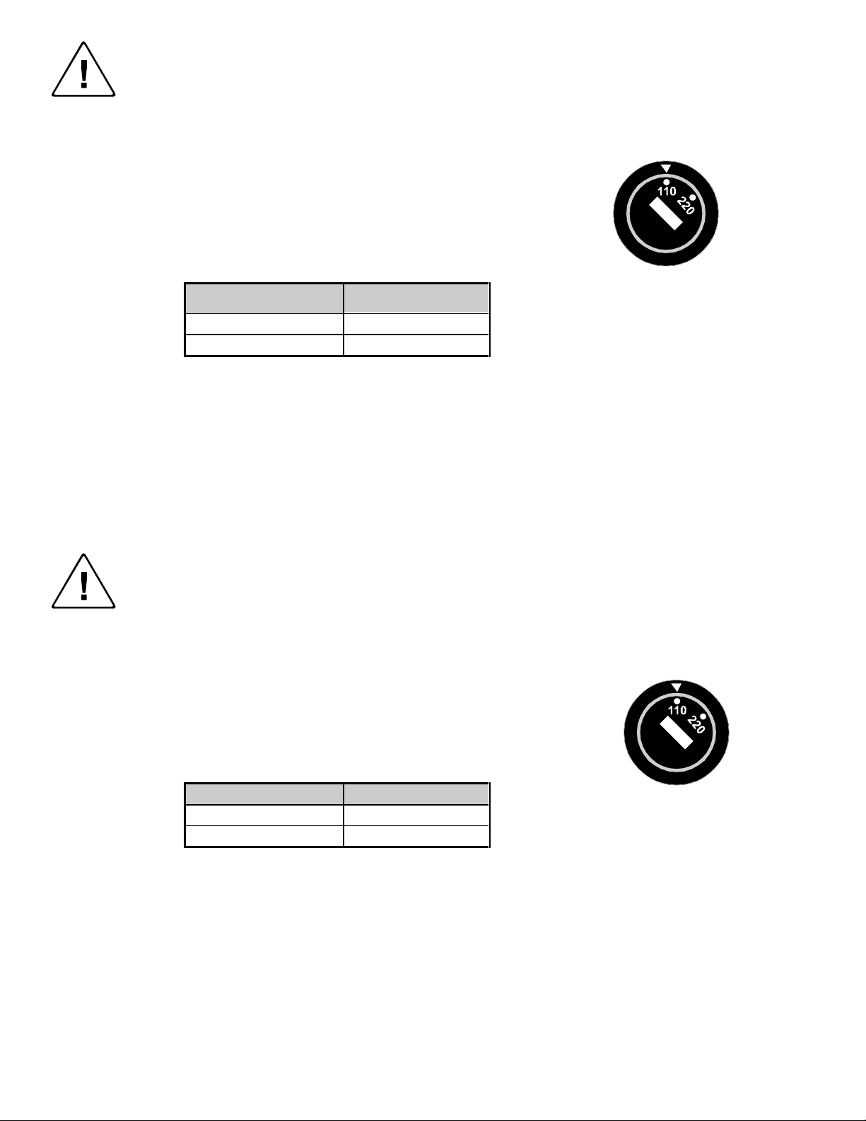
The voltage selector is a round switch located next to the A/C power input connector which looks
like this:
Using a straight slot screwdriver or small coin, rotate the selector to the correct position so that
the arrow lines up with 110 or 220 as appropriate for local power line voltage as indicated in the
chart below:
Local A/C Voltage Voltage Selector Setting
110 ~ 120 VAC 110
220 ~ 240 VAC 220
For all Models:
No serviceable parts inside the unit. Refer service to a qualified technician.
For Models with Internal or External Fuses:
For continued protection against fire hazard, replace only with same type and rating of fuse.
For IN2001 / IN3234 / IN3236 / IN3502 / IN3504 / IN3506 / IN3562 / IN3564 / IN3566 / IN3572 / IN3574 / IN3576:
Caution: Double pole / neutral fusing.
For all Models with Integral Lithium Battery:
Caution: Danger of explosion if battery is incorrectly replaced. Replace only with the same or equivalent type recommended by
the manufacturer. Dispose of used batteries according to the manufacturer’s instructions.
Instructions d’installation et de sécurité
Pour les modèles sans interrupteur de courant:
La prise de courant d’alimentation sera installé près de l’équipement et sera accessible.
Pour les modèles avec un sélecteur d’alimentation 110V/220V:
Attention: Avant de connecter l’appareil au circuit d’alimentation, le sélecteur de courant doit être positionné sur la sélection
appropriée correspondant au voltage du circuit de courant alternatif local. Une mauvaise sélection peut engendrer des
dommages à l’appareil et créer un danger d’incendie.
Le sélecteur d’alimentation est un commutateur rond positionné près du connecteur
d’alimentation. Il se représente comme suit:
A l’aide d’un tourne-vis plat ou d’une pièce de monnaie, le sélecteur peut être tourné dans la
position adéquate en veillaut que la flèche corresponde avec 110 ou 220, en fonction de la
valeur du circuit de courant local. (Voir tableau ci-dessous)
Circuit local AC Position Sélecteur
110 ~ 120 VAC 110
220 ~ 240 VAC 220
Pour tout les modèles:
Pas de composants à entretenir à l’intérieur. Confiez toute réparation à un technicien qualifié.
Pour les modèles équipés de fusibles internes ou externes:
Afin d’éviter tout danger d’incendie, ne remplacer qu’avec le même type et la même valeur de fusible.
Pour IN2001 / IN3234 / IN3236 / IN3502 / IN3504 / IN3506 / IN3562 / IN3564 / IN3566 / IN3572 / IN3574 / IN3576:
Attention: Double pôle / fusible au neutre.
Pour tout les modèles avec une batterie au lithium interne:
Attention: Danger d’explosion si la batterie est incorrectement remplacée. Ne remplacez la batterie qu’avec le même modèle,
ou avec un modèle recommandé par le constructeur. Traitez les batteries usagées selon les instructions du fabricant, ou selon
les normes écologiques en viguer.
Page 3
Installations und Sicherheitshinweise
Für Geräte ohne Netzschalter:
Die Netzsteckdose soll in de Nähe des Gerätes installiert und frei zugänglich sein.
Für Geräte mit 110 / 220V Spannungswähler:
Achtung: Bevor Sie dem Gerät Spann ung zuführen, muß der Spannungswähler entsprechend der Spannung des lokalen
Wechselspannungsnetzes eingestellt werden. Die falsche Stellung des Spannungswählers
kann eine Beschädigung des Gerätes und möglicherweise ein Feuer verursachen.
Der Spannungswähler ist ein runder Schalter in der Nähe der Netzeingangsbuchse mit
folgendem Aussehen:
Drehen Sie den Wähler mit einem normalen Schraubenzieher oder einer kleinen Münze so, daß
der Pfeil auf die 110 oder 220 zeigt, entsprechend der Spannung Ihr es lokalen Netzes wie hier
angezeigt:
Lokale Netzwechselspannung Stellung des
110 ~ 120 V 110
220 ~ 240 V 220
Für alle Geräte:
Keine Wartung innerhalb des Gerätes notwendig. Reparaturen nur durch einen Fachmann!
Für Geräte mit interner oder externer Sicherung:
Für dauernden Schutz gegen Feuergefahr darf die Sicherung nur gegen eine andere gleichen Typs und gleicher Nennleistung
ausgewechselt werden.
Für IN2001 / IN3234 / IN3236 / IN3502 / IN3504 / IN3506 / IN3562 / IN3564 / IN3566 / IN3572 / IN3574 / IN3576:
Achtung: Allpolige Absicherung
Für alle Geräte mit eingebauter Lithium Batterie:
Achtung: Explosionsgefahr bei falschem Batterieeinsatz. Batterie nur erstzen durch den gleichen oder entsprechenden Typ
wie vom Hersteller empfohlen. Entsorgung verbrauchter Batterien nur nach den Anweisungen des Herstellers.
Spannungswählers
Instalacion E Instrucciones de Seguridad
Modelos Sin Interruptor:
La conexión debe ser instalada cerca del equipo y debe ser accesible.
Modelos con Selector de Voltaje de 110/220V:
Precaución: Antes de operar esta unidad, el selector de voltaje debe instalarse de forma que corresponda a la linea de voltaje
local. Instalación inadecuada del selector de voltaje puede causar daño a la unidad y originar un incendio.
El selector de voltaje es un cambia vía redondo localizado cerca de la conexión electrica, como se
ve en el dibujo:
Use un destornillador comun o una moneda pequeña, mueva el selector a la posición correcta, de
forma que las flechas indiquen 110 o 220 de acuerdo con el voltaje local, como esta indicado a
continuación.
Voltaje Local A/C Selector de Voltaje
110 ~ 120 VAC 110
220 ~ 240 VAC 220
Para Todos Los Modelos:
Dentro de la unidad , no hay partes para reparar. Llame un tecnico calificado.
Modelos con Fusibles Internos o Externos:
Para prevenir un incendio, reemplace solo con el mismo tipo de fusible.
Modelos IN2001 / IN3234 / IN3236 / IN3502 / IN3504 / IN3506 / IN3562 / IN3564 / IN3566 / IN3572 / IN3574 / IN3576:
Precaución: Double Polo / Fusible Neutral.
Modelos con Bateria de Lithiun Interna:
Precaución: Peligro de explosión si la batería es reemplacada incorrectamente. Reemplace solamente con la misma clase de
batería, o una equivalente recomendada por el fabricante. Deseche las baterías usadas de acuerdo con las instrucciones del
fabricante.
Page 4

CE COMPLIANCE
All products exported to Europe by Inline, Inc. after January 1, 1997 have been
tested and found to comply with EU Council Directive 89/336/EEC. These
devices conform to the following standards:
EN50081-1 (1991), EN55022 (1987)
EN50082-1 (1992 and 1994), EN60950-92
Shielded interconnect cables must be employed with this equipment to
ensure compliance with the pertinent Electromagnetic Interference (EMI)
and Electromagnetic Compatibility (EMC) standards governing this device.
FCC COMPLIANCE
This device has been tested and found to comply with the limits for a Class A
digital device, pursuant to Part 15 of the FCC rules. These limits are designed to
provide against harmful interference when equipment is operated in a
commercial environment. This equipment generates, uses and can radiate radio
frequency energy and, if not installed and used in accordance with the instruction
manual, may cause harmful interference to radio communications. Operation of
equipment in a residential area is likely to cause harmful interference, in which
case the user will be required to correct the interference at their own expense.
Page 5

DESCRIPTION
The IN6901 Series II and IN6902 Series II are serial command to contact closure converters. After
receiving RS-232 commands the units will open, close, toggle, or pulse (short temporary toggle) their
relays, providing latching or momentary contact closures. The IN6901 and IN6902 allow devices with
contact closure controls to be remotely controlled using serial commands.
The IN6901 and IN6902 operate identically. The main difference between the units is their size and the
number of relays they contain:
The IN6901 has 6 relays.
The IN6902 has 17 relays.
The IN6901 / IN6902 are ideal for adding RS-232 remote control functionality to INLINE 3500 Series
switchers including the following products:
IN3502 IN3562 IN3572
IN3504 IN3554 IN3564 IN3574
IN3506 IN3556 IN3566 IN3576
The IN6901 / IN6902 may be used to control many types of equipment which accept momentary or
latching contact closure control including switchers, motorized screens, cassette decks, lighting, drapes,
and projector lifts.
1
Since the IN6901 and IN6902 have multiple relays, they can also control multiple switchers. For
instance, a single IN6901 with 6 relays could control two IN3500 Series 2-Input switchers and one 4Input switcher. One IN6902 (17 relays) could control four IN3500 Series 4-Input switchers and one 2Input switcher from a single RS-232 control port.
©1996-1998 - INLINE, INC. IN6901 / IN6902 OPERATION MANUAL - REV. 2.1 12/01/98
Page 6

2
USING RS-232 CONTROL
The IN6901 / IN6902 include an 9-pin D male remote control port which will accept serial commands
from a control system, computer serial port, or any other device capable of sending out serial ASCII
commands at 1200 baud. These commands may be used to control individual relays, multiple relays or
all relays. Using the appropriate RS-232 codes, the unit relays may be commanded to open, close, toggle
to the opposite state, or pulse (temporarily change to the opposite state for 50 msec and return).
When a relay is selected to close, the contact closure is made between the relay and the common. Thus,
closing Relay 1 on the IN6901 results in a closure between pins 6 and 7.
A complete listing of RS-232 codes is included on page 4.
COMMUNICATION PROTOCOL
1200 baud
No parity check
8 data bits
1 stop bit
COMMAND CODE STRUCTURE
All commands sent to the unit must contain a leading code, the command code, and an ending code.
Each command must be completely executed before the unit will accept a new command. When a
command is completed, the unit provides a response code:
“OK” indicates the command was received and executed.
“ERR” indicates there is a problem with the code and the command was not executed.
The IN6901 and IN6902 always look for serial commands with the following delimiters: [ ] Commands
sent without these delimiters will be ignored.
A complete command consists of:
[ The leading code
RLY01C The command code. (This would cause relay 01 to close)
] The ending code
Sample command codes:
[RLY02O] Open Relay 2
[RLY12T] Toggle Relay 12
[LCCCOOO] Load and execute the following states: Relays 01, 02, 03 Closed
Relays 04, 05, 06 Open
IN6901 / IN6902 OPERATION MANUAL - REV. 2.1 12/01/98 ©1996-1998 - INLINE, INC.
Page 7

RS-232 CONTROL PORT PIN-OUTS - IN6901 / IN6902
Connector: 9-Pin D male
Pin Signal
2 Receive
3 Transmit
7 Ground
OUTPUT RELAY PIN-OUTS: IN6901
Connector: 9-Pin D female
Pin Signal
1 Relay 6
2 Relay 5
3 Relay 4
4 Relay 3
5 Relay 2
6 Relay 1
7 Common
8 No connection
9 No connection
3
OUTPUT RELAY PIN-OUTS: IN6902
Connector: 25-Pin D female
Pin Signal Pin Signal
1 Relay 13 14 +5V DC
2 Relay 12 15 +5V DC
3 Relay 11 16 No Connection
4 Relay 10 17 No Connection
5 Relay 9 18 Ground
6 Relay 8 19 Ground
7 Relay 7 20 No Connection
8 Relay 6 21 Common
9 Relay 5 22 Relay 17
10 Relay 4 23 Relay 16
11 Relay 3 24 Relay 15
12 Relay 2 25 Relay 14
13 Relay 1
©1996-1998 - INLINE, INC. IN6901 / IN6902 OPERATION MANUAL - REV. 2.1 12/01/98
Page 8

4
RS-232 COMMAND CODES - FIRMWARE VERSION 1.0A
nn: Any two digit number ranging from 00 to 17 (00 selects all relays.)
COMMAND DESCRIPTION RESPONSE
[RLYnnC] Close relay nn. [OK]
[RLYnnO] Open relay nn. [OK]
[RLYnnT] Toggle relay nn. The relay will switch to the opposite state (If it was
[OK]
open, it will close, and vice-versa.
[RLYnnP] Pulse relay nn. The relay will switch to the opposite state for 50 msec
[OK]
and then return.
[Lr1r2...rn] Load and execute the state for relays r1, r2, ...rn. The first character
[OK]
after "L" is the state for relay 1, the second for relay 2, etc. The
command can range from 4 characters (load the state of relay 1 only) to
20 characters (load the state for all 17 relays for the IN6902). The
states are as follows:
N Normal. The relay remains in the same state
C Close the relay
O Open the relay
T Toggle the relay
Ex. 1: [LCCCOOO]
The above example will perform the following:
Close relays 1, 2 and 3
Open relays 4, 5 and 6
Ex. 2: [LNNTTCCOO]
The above example will perform the following:
Toggle relays 3 and 4
Close relays 5 and 6
Open relays 7 and 8 for the IN6902.
Relays 1 and 2 remain unchanged for the IN6901.
For the IN6902, relays 1, 2, and 9-17 remain
unchanged.
Note: The Pulse command "P" cannot be used with this command.
[INF0] Get the firmware version [IN690X V1.0a]
IN6901 / IN6902 OPERATION MANUAL - REV. 2.1 12/01/98 ©1996-1998 - INLINE, INC.
Page 9

SPECIFICATIONS
5
IN6901
RS-232 to 6 Control Relays
RS-232 Control Input
Connector type
Control Signal
Command Codes [ ]
Output
Connector type
Relay Maximum Load
Dimensions
Power
Size
Height: 0.9" Width: 3.5"
9-Pin D male 9 Pin D male
1200 Baud, No Parity, 8 Data Bits, 1 Stop Bit
9-Pin D female 25- Pin D female
1 Amp @ 30V
9V 500 mA DC 9V 500 mA DC
Depth: 2.75"
IN6902
RS-232 to 17 Control Relays
Height: 1" Width: 7.75"
Depth: 4.1"
Shipping Weight
1 lb. 2 lbs.
©1996-1998 - INLINE, INC. IN6901 / IN6902 OPERATION MANUAL - REV. 2.1 12/01/98
Page 10

6
WARRANTY
♦
INLINE warrants the equipment it manufactures to be free from defects in materials and
workmanship.
♦
If equipment fails because of such defects and INLINE is notified within two (2) years from the
date of shipment, INLINE will, at its option, repair or replace the equipment at its plant,
provided that the equipment has not been subjected to mechanical, electrical, or other abuse or
modifications.
♦
Equipment that fails under conditions other than those covered will be repaired at the current
price of parts and labor in effect at the time of repair. Such repairs are warranted for ninety (90)
days from the day of re-shipment to the Buyer.
♦
This warranty is in lieu of all other warranties expressed or implied, including without
limitation, any implied warranty or merchantibility or fitness for any particular purpose,
all of which are expressly disclaimed.
The information in this manual has been carefully checked and is believed to be accurate. However,
Inline, Inc. assumes no responsibility for any inaccuracies that may be contained in this manual. In no event will
Inline, Inc. be liable for direct, indirect, special, incidental, or consequential damages resulting from any defect
or omission in this manual, even if advised of the possibility of such damages. The technical information
contained herein regarding IN6901 / IN6902 features and specifications is subject to change without notice.
All Rights Reserved © Copyright 1996-1998
INLINE, INC. ♦ 22860 SAVI RANCH PARKWAY ♦ YORBA LINDA, CA 92887
©
(800) 882-7117 ♦ (714) 921-4100 ♦ FAX (714) 921-4160
♦ www.inlineinc.com
IN6901 / IN6902 OPERATION MANUAL - REV. 2.1 12/01/98 ©1996-1998 - INLINE, INC.
 Loading...