

Page 1
Preliminary Operation Manual
IN3600 Series 6-Input Switchers
IN3606 RGBS Switcher
IN3654 / IN3656 RGBHV Switchers
IN3666 VGA Switcher
®
Page 2
Installation and Safety Instructions
For Models without a Power Switch:
The socket outlet shall be installed near the equipment and shall be accessible.
For Models with 110 / 220V Power Selector:
Caution: Before applying power to this unit, the voltage selector must be set to the appropriate setting to match local A/C line
voltage. Improper setting of the voltage selector may cause damage to the unit and create a potential fire hazard.
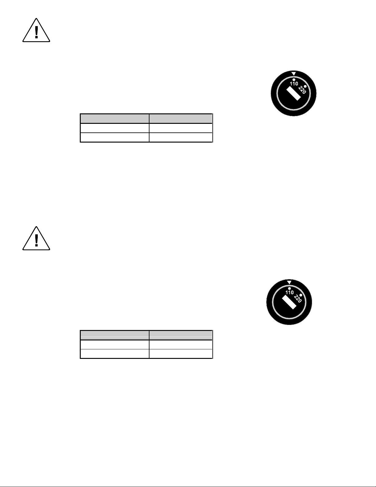
The voltage selector is a round switch located next to the A/C power input connector which looks
like this:
Using a straight slot screwdriver or small coin, rotate the selector to the correct position so that
the arrow lines up with 110 or 220 as appropriate for local power line voltage as indicated in the
chart below:
Local A/C Voltage Voltage Selector Setting
110 ~ 120 VAC 110
220 ~ 240 VAC 220
For all Models:
No serviceable parts inside the unit. Refer service to a qualified technician.
For Models with Internal or External Fuses:
For continued protection against fire hazard, replace only with same type and rating of fuse.
For IN2001 / IN3234 / IN3236 / IN3502 / IN3504 / IN3506 / IN3562 / IN3564 / IN3566 / IN3572 / IN3574 / IN3576:
Caution: Double pole / neutral fusing.
For all Models with Integral Lithium Battery:
Caution: Danger of explosion if battery is incorrectly replaced. Replace only with the same or equivalent type recommended by
the manufacturer. Dispose of used batteries according to the manufacturer’s instructions.
Instructions d’installation et de sécurité
Pour les modèles sans interrupteur de courant:
La prise de courant d’alimentation sera installé près de l’équipement et sera accessible.
Pour les modèles avec un sélecteur d’alimentation 110V/220V:
Attention: Avant de connecter l’appareil au circuit d’alimentation, le sélecteur de courant doit être positionné sur la sélection
appropriée correspondant au voltage du circuit de courant alternatif local. Une mauvaise sélection peut engendrer des
dommages à l’appareil et créer un danger d’incendie.
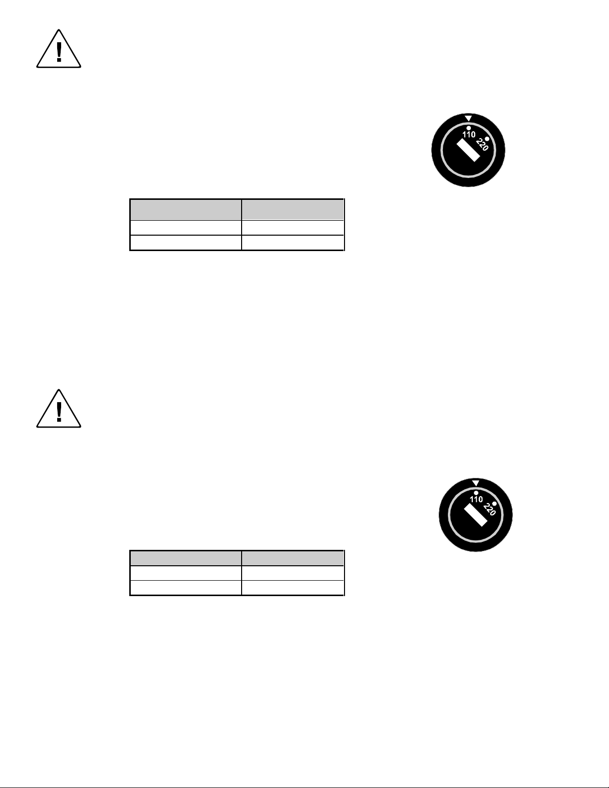
Le sélecteur d’alimentation est un commutateur rond positionné près du connecteur
d’alimentation. Il se représente comme suit:
A l’aide d’un tourne-vis plat ou d’une pièce de monnaie, le sélecteur peut être tourné dans la
position adéquate en veillaut que la flèche corresponde avec 110 ou 220, en fonction de la
valeur du circuit de courant local. (Voir tableau ci-dessous)
Circuit local AC Position Sélecteur
110 ~ 120 VAC 110
220 ~ 240 VAC 220
Pour tout les modèles:
Pas de composants à entretenir à l’intérieur. Confiez toute réparation à un technicien qualifié.
Pour les modèles équipés de fusibles internes ou externes:
Afin d’éviter tout danger d’incendie, ne remplacer qu’avec le même type et la même valeur de fusible.
Pour IN2001 / IN3234 / IN3236 / IN3502 / IN3504 / IN3506 / IN3562 / IN3564 / IN3566 / IN3572 / IN3574 / IN3576:
Attention: Double pôle / fusible au neutre.
Pour tout les modèles avec une batterie au lithium interne:
Attention: Danger d’explosion si la batterie est incorrectement remplacée. Ne remplacez la batterie qu’avec le même modèle,
ou avec un modèle recommandé par le constructeur. Traitez les batteries usagées selon les instructions du fabricant, ou selon
les normes écologiques en viguer.
Page 3
Installations und Sicherheitshinweise
Für Geräte ohne Netzschalter:
Die Netzsteckdose soll in de Nähe des Gerätes installiert und frei zugänglich sein.
Für Geräte mit 110 / 220V Spannungswähler:
Achtung: Bevor Sie dem Gerät Spann ung zuführen, muß der Spannungswähler entsprechend der Spannung des lokalen
Wechselspannungsnetzes eingestellt werden. Die falsche Stellung des Spannungswählers
kann eine Beschädigung des Gerätes und möglicherweise ein Feuer verursachen.
Der Spannungswähler ist ein runder Schalter in der Nähe der Netzeingangsbuchse mit
folgendem Aussehen:
Drehen Sie den Wähler mit einem normalen Schraubenzieher oder einer kleinen Münze so, daß
der Pfeil auf die 110 oder 220 zeigt, entsprechend der Spannung Ihr es lokalen Netzes wie hier
angezeigt:
Lokale Netzwechselspannung Stellung des
110 ~ 120 V 110
220 ~ 240 V 220
Für alle Geräte:
Keine Wartung innerhalb des Gerätes notwendig. Reparaturen nur durch einen Fachmann!
Für Geräte mit interner oder externer Sicherung:
Für dauernden Schutz gegen Feuergefahr darf die Sicherung nur gegen eine andere gleichen Typs und gleicher Nennleistung
ausgewechselt werden.
Für IN2001 / IN3234 / IN3236 / IN3502 / IN3504 / IN3506 / IN3562 / IN3564 / IN3566 / IN3572 / IN3574 / IN3576:
Achtung: Allpolige Absicherung
Für alle Geräte mit eingebauter Lithium Batterie:
Achtung: Explosionsgefahr bei falschem Batterieeinsatz. Batterie nur erstzen durch den gleichen oder entsprechenden Typ
wie vom Hersteller empfohlen. Entsorgung verbrauchter Batterien nur nach den Anweisungen des Herstellers.
Spannungswählers
Instalacion E Instrucciones de Seguridad
Modelos Sin Interruptor:
La conexión debe ser instalada cerca del equipo y debe ser accesible.
Modelos con Selector de Voltaje de 110/220V:
Precaución: Antes de operar esta unidad, el selector de voltaje debe instalarse de forma que corresponda a la linea de voltaje
local. Instalación inadecuada del selector de voltaje puede causar daño a la unidad y originar un incendio.
El selector de voltaje es un cambia vía redondo localizado cerca de la conexión electrica, como se
ve en el dibujo:
Use un destornillador comun o una moneda pequeña, mueva el selector a la posición correcta, de
forma que las flechas indiquen 110 o 220 de acuerdo con el voltaje local, como esta indicado a
continuación.
Voltaje Local A/C Selector de Voltaje
110 ~ 120 VAC 110
220 ~ 240 VAC 220
Para Todos Los Modelos:
Dentro de la unidad , no hay partes para reparar. Llame un tecnico calificado.
Modelos con Fusibles Internos o Externos:
Para prevenir un incendio, reemplace solo con el mismo tipo de fusible.
Modelos IN2001 / IN3234 / IN3236 / IN3502 / IN3504 / IN3506 / IN3562 / IN3564 / IN3566 / IN3572 / IN3574 / IN3576:
Precaución: Double Polo / Fusible Neutral.
Modelos con Bateria de Lithiun Interna:
Precaución: Peligro de explosión si la batería es reemplacada incorrectamente. Reemplace solamente con la misma clase de
batería, o una equivalente recomendada por el fabricante. Deseche las baterías usadas de acuerdo con las instrucciones del
fabricante.
Page 4
CE COMPLIANCE
All products exported to Europe by Inline, Inc. after January 1, 1997 have been
tested and found to comply with EU Council Directive 89/336/EEC. These
devices conform to the following standards:
EN50081-1 (1991), EN55022 (1987)
EN50082-1 (1992 and 1994), EN60950-92
Shielded interconnect cables must be employed with this equipment to
ensure compliance with the pertinent Electromagnetic Interference (EMI)
and Electromagnetic Compatibility (EMC) standards governing this device.
FCC COMPLIANCE
This device has been tested and found to comply with the limits for a Class A
digital device, pursuant to Part 15 of the FCC rules. These limits are designed to
provide against harmful interference when equipment is operated in a
commercial environment. This equipment generates, uses and can radiate radio
frequency energy and, if not installed and used in accordance with the instruction
manual, may cause harmful interference to radio communications. Operation of
equipment in a residential area is likely to cause harmful interference, in which
case the user will be required to correct the interference at their own expense.
Page 5

DESCRIPTION
The IN3600 Series includes four high performance analog video switchers with four or six inputs and
one output. The IN3600 Series switchers are designed to route several high resolution source signals to
an attached desktop data monitor, presentation monitor or data projector. Users may select the desired
input channel using front panel buttons or via remote control using an optional wired remote or control
system. The IN3600 Series has six front panel buttons that may be used to select the desired input
channel. Any time the unit is powered up, Input 1 is automatically selected. All non-selected channels
are terminated to 75 Ohms. The output signal may be blanked (no input selected) by pressing the Blank
button. Returning to normal operation (or un-blanking) is accomplished by pressing the Blank button
again. Input channels may also be selected remotely by using an optional IN3590 wired remote or a
control system (see Remote Control Operation on page 4 for more details). The IN3600 Series
Switchers offer easy operation and the following features:
♦ 300 MHz Bandwidth - switchers route ultra-high resolution video signals with no signal loss
♦ Design ensures compatibility with a wide range of video and audio signals
♦ Front Panel Channel Selection Controls and LED Indicators
♦ Contact Closure control port for remote selection of input channel
♦ Wide flexibility in programming for various configurations.
1
COMPATIBILITY
The IN3606 / IN3656 / IN3666 switchers are active devices which will switch a wide variety of signals.
The four switcher models are very similar in operation and have the following differences:
Model Input / Output
Connectors
IN3606
IN3554/
(4) Female BNC 4 RGBS, RGsB, Component, Y/C, Composite
(5) Female BNC 5 RGBHV, RGBS, RGsB, Component, Y/C,
IN3656
IN3666
15-Pin HD 6 RGBHVS, RGBHV, RGBS, RGsB, Component,
Number of Discrete
Signal Paths
Signal Compatibility
Video, Composite Monochrome with Sync
Composite Video, Composite Monochrome with
Sync
Y/C, Composite Video Composite Monochrome
with Sync
© 1998 - INLINE, INC. IN3606 / IN3656 / IN3666 OPERAT ION MANUAL - REV. 1.1 11/27/99
Page 6

2
INSTALLATION
This section offers step-by-step instructions for installing IN3600 Series switchers.
1. Connect all sources to the input connectors. Unused inputs do not need to be terminated.
2. An interface may be required for each computer video signal source in order to split off a signal for
each local monitor, bring all signals into the appropriate format, and amplify the signal to
compensate for long input/output cable runs.
3. Connect the IN3600 Series switcher output to the display device.
4. Apply AC power to the unit.
It is very important that all input / output connections be made utilizing high resolution coaxial cables.
Proper cable selection is critical to overall system performance, especially when working with high
frequency signals and/or long cable runs. The IN7000, IN7200 or IN7300 Series cables (available with
4 or 5 BNC connectors) or IN8000 Series VGA extension cables are recommended for best results.
OPERATION
Power Switch
The POWER switch is located on the back of the unit. When power is turned on, the unit will default to
Input 1 and the Input 1 LED will light to indicate that the unit is active. When powering up several units
that are linked together in a Master/Slave arrangement, it is required that either all units be powered on
simultaneously or that the Master unit be powered on last. This is to allow the Master unit to poll all
Slave units to determine how many are used in a multiple unit system.
Modes of Operation
The IN3600 Series switchers provide various modes of operation. These modes include:
♦ Manual Mode
In the Manual Mode, inputs from a single or multiple set of units are accessed by pressing the
corresponding front panel switch for that input. In this mode, RGB delay and Vertical Interval Switching
can be enabled. (See Programming Options)
♦ Scan Mode
In the Scan Mode, the unit switches between inputs at a specified time period. The time period is
programmable in 2.5 second increments up to 37.5 seconds. When the Blank button is used, all scanning
stops and individual inputs can be selected and viewed. When Blank is depressed again, scanning will
resume at the input it last left off at. In this mode, RGB delay and Vertical Interval Switching are
disabled.
♦ Autoswitching Mode
In the Autoswitching Mode, all inputs are scanned for active signals. The highest number input with an
active signal is switched to the output. (i.e. If inputs 2,3 and 4 have active inputs, input 4 will be switched
to the ouput.)
In all modes, the following options are available:
♦ Blank = nothing or sync
♦ Front Panel = enabled or disabled
♦ RS232 communication baud rates of 1200, 2400, 4800 or 9600
IN3606 / IN3656 / IN3666 OPERATI ON MANUAL - REV. 1.1 11/27/99 ©1998 - INLINE, INC.
Page 7

Programming Options
♦ RGB Delay
Only H and V inputs of a particular input is switched immediately. This is to allow for resizing and
syncing of monitors before the RGB picture elements are sent. The RGB inputs are switched a time
period afterwards. This time period is programmable in half second increments from one half second to
7.5 seconds. (See Programming Procedures)
♦ Vertical Interval Switching
Switching between inputs occurs during the vertical interval sync pulse therefore eliminating screen jitter
while switching.
Programming Procedures
There are two ways of programming the IN3600 Series. One is by RS232 communications, the other by
power up settings. Power up settings are accomplished by holding a particular input button while
simultaneously powering up the unit.
POWER ON SETTINGS
To Reset Unit to Factory Defaults - Hold down INPUT 1 button during power-up.
The default settings are:
Front Panel enabled
Vertical Interval Switching off
Master Switcher
1200 baud
“[ ]” command codes
Manual Switching (Scan off)
Blank sends nothing to output
3
To Set Miscellaneous Functions - Hold down INPUT2 button during power-up:
A. BLANK LED goes solid
B. Letting go of INPUT2, BLANK LED flashes
C. Switches INPUT1 through INPUT4 are toggling options:
INPUT1 on = Vertical Switching onoff = Vertical Switching off
INPUT2 on = Front Panel disabled off = Front Panel enabled
INPUT3 on = Auto Switching on off = Auto Switching off
INPUT4 on = Sync on Blank off = Nothing on Blank
D. Depressing BLANK button saves this part of configuration and Blank LED flashes slower
E. Switches INPUT1 and INPUT2 are alternate action selections:
INPUT1 on = Master mode
INPUT2 on = Slave mode
F. Depressing BLANK button saves this part of configuration and Blank LED turns off.
© 1998 - INLINE, INC. IN3606 / IN3656 / IN3666 OPERAT ION MANUAL - REV. 1.1 11/27/99
Page 8

4
To set Input Scan Options - Hold down INPUT3 button during power-up:
A. BLANK LED goes solid
B. Letting go of INPUT3, BLANK LED flashes
C. Press one of the INPUT buttons to select inputs to scan:
INPUT1 Disable scanning (If entered, skips to end)
INPUT2 Scan Inputs 1 to 2
INPUT3 Scan Inputs 1 to 3
INPUT4 Scan Inputs 1 to 4
(And for the IN3656 switcher:)
INPUT5 Scan Inputs 1 to 5
INPUT6 Scan Inputs 1 to 6
(INPUT1 LED will go on to show scan enabled and 2-6 LED will go on to show to what
input)
D. The BLANK LED now flashes at a slower rate
E. Switches INPUT1 through INPUT4 are toggling options:
INPUT1 Add 2.5 seconds of scan delay
INPUT2 Add 5.0 seconds of scan delay
INPUT3 Add 10.0 seconds of scan delay
INPUT4 Add 20.0 seconds of scan delay
(Up to 37.5 seconds of delay can be programmed in)
F. Depressing BLANK button saves configuration and Blank LED goes off
To set RGB Delay Options - Hold down INPUT4 button during power-up:
A. BLANK LED goes solid
B. Letting go of INPUT4, BLANK LED flashes
C. Switches INPUT1 through INPUT4 are toggling options:
INPUT1 Add 0.5 second of RGB delay
INPUT2 Add 1.0 seconds of RGB delay
INPUT3 Add 2.0 seconds of RGB delay
INPUT4 Add 4.0 seconds of RGB delay
(Up to 7.5 seconds of delay can be programmed in)
D. Depressing BLANK button saves configuration and Blank LED goes off
To set RS-232 Serial Control Baud Rate - Hold down BLANK button during power-up :
A. BLANK LED goes solid
B. Letting go of BLANK, BLANK LED flashes
C. Switches INPUT1 through INPUT4 select baud rate:
INPUT1 on = 1200 baud
INPUT2 on = 2400 baud
INPUT3 on = 4800 baud
INPUT4 on = 9600 baud
D. Depressing BLANK button saves configuration and Blank LED goes off
Calling these up will also show present settings. (i.e. INPUT2 settings, INPUT2 LED may be on showing
that the front panel is already enabled)
IN3606 / IN3656 / IN3666 OPERATI ON MANUAL - REV. 1.1 11/27/99 ©1998 - INLINE, INC.
Page 9

RS232 Commands
Programming and information polling is also possible by RS232 communication through the RS232
connector on the back of the unit. Connection is made via an IN9317 connector wired to either a 9-pin D
or 25-pin D connector. The input labeled GND (pin2) goes to either pin 7 of a 25 pin connector or pin 5
of a 9 pin. The input labeled TX (pin1) goes to either pin 3 of a 25 pin connector or pin 2 of a 9 pin
connector. The input labeled RX (pin3) goes to either pin 2 of a 25 pin connector or pin 3 of a 9 pin
connector. Default communication settings are 8 bits, 1 stop bit, no parity and 1200 baud. All commands
sent to the unit must be enclosed in brackets. When linking units together, up to four units can be
programmed with different brackets for an ID when communicating with all units. Possible brackets are [
and ], { and}, ( and ), < and >. The default brackets are [ and ]. So a command sent to the unit would look
like: [BLANK0]. Letters are not case sensitive and can be written as BLANK or blank. Possible
commands are:
ACI3 Set to 1200 Baud
ACI4 Set to 2400 Baud
ACI5 Set to 4800 Baud
ACI6 Set to 9600 Baud
BLANK0 Blank Output (Same as Blank key)
BLANK1 Un-Blank Output (Return to previous channel)
BLANKB Set for BLANK=BLANK
BLANKS Set for BLANK=SYNC
CH0 Select Blank (Same as Blank0)
CH1,2,3,4,5,6 Select Channel 1,2,3,4,5,6
CMDCD0,1,2,3Set unit for commands with [ ], { }, ( ) or < > respectively
FP Front Panel Enable/Disable Toggle
FP0 Front Panel Disable
FP1 Front Panel Enable
INF0 Display Model Number and Software Version
INF1 Display Current Channel
INF2 Display all setup parameters
Mode0 Manual Mode
Mode1 Autoswitching
Mode2 Turn on Vertical Switching
Mode3 Turn off Vertical Switching
Mode4 Set as Master
Mode5 Set as Slave
RGBx x=RGB Delay Time (i.e. [RGB2.5] )
Possible allowable times are: 0.5 seconds 1.0 seconds 1.5 seconds
2.0 seconds 2.5 seconds 3.0 seconds
3.5 seconds 4.0 seconds 4.5 seconds
5.0 seconds 5.5 seconds 6.0 seconds
6.5 seconds 7.0 seconds 7.5 seconds
Scan0 Disable Scanning
Scan1 Enable Scanning
Scan2,3,4,5,6 Scan to Channels 2,3,4,5,6
5
© 1998 - INLINE, INC. IN3606 / IN3656 / IN3666 OPERAT ION MANUAL - REV. 1.1 11/27/99
Page 10

6
ScantX X=Scan Time between Channels (i.e. [SCANT12.5] would set the scan time to 12.5
seconds)
Possible allowable times are: 2.5 seconds 5.0 seconds 7.5 seconds
10.0 seconds 12.5 seconds 15.0 seconds
17.5 seconds 20.0 seconds 22.5 seconds
25.0 seconds 27.5 seconds 30.0 seconds
32.5 seconds 35.0 seconds 37.5 seconds
REMOTE CONTROL OPERATION
The IN3600 Series switchers have a REMOTE CONTROL port which allows these units to be remotely
controlled. Channels can be selected through the remote port by providing contact closures between the
appropriate pins. The port also includes a +5V power supply and tally outputs. Several contact closure
type control devices are available including:
IN3590 - An optional hard wired remote designed to work with IN3600 Series switchers.
IN6901 / IN6902 RS232 to Contact Closure Converters - allow IN3600 Series switchers and
other INLINE devices with contact closure control ports to be controlled by RS232 sources such
as control systems and computer serial ports.
Control System - many control systems are capable of providing contact closures.
Control Parameters
In order to select a channel, the channel select pin (pins 1 - 6) must be connected to Common (pin 7 or 8).
The contact closures may be momentary or continuous (latching).
Example: To switch to Input Channel #4, apply a contact closure between Pin 4 and Pin 7.
Tally Output
The REMOTE CONTROL port also provides tally outputs (pins 10 - 15) which may be used to trigger
other devices, provide feedback to a control system, or light indicator lights on a custom remote control
panel. When a channel is selected, either from the front panel or through the REMOTE CONTROL port,
the Tally Output for that channel is switched on. The Tally Output can switch voltages of up to 50 volts
and current up to 1.5 amps.
Control Port Pin Outs
The REMOTE CONTROL port is a Female 15 Pin D connector with the
following pin outs:
Pin 1 Select Channel 1 Pin 9 +5 volts DC
Pin 2 Select Channel 2 Pin 10 *Tally output for Channel 6
Pin 3 Select Channel 3 Pin 11 *Tally output for Channel 5
Pin 4 Select Channel 4 Pin 12 Tally output for Channel 4
Pin 5 Select Channel 5 Pin 13 Tally output for Channel 3
Pin 6 Select Channel 6 Pin 14 Tally output for Channel 2
Pin 7 Common Pin 15 Tally output for Channel 1
Pin 8 Common
IN3606 / IN3656 / IN3666 OPERATI ON MANUAL - REV. 1.1 11/27/99 ©1998 - INLINE, INC.
Page 11

IN3546R STEREO AUDIO SWITCHER
The IN3546R Stereo Audio Switcher may be attached to the IN3600 Series via the REMOTE
CONTROL port. This provides a +5V power supply for the IN3546R Switcher and a control link.
When the IN3546R is attached to the control port using an IN9112 control link cable, the IN3546R will
automatically switch to the appropriate input channel, mirroring the input selected on the attached
switcher and adding audio-follow-video capability to the switcher.
SPECIFICATIONS
IN3606 IN3654 / IN3656 IN3666
Inputs
Connector type
Maximum Signal
Components per Input
Signal Compatibility
Output
Connector type
Bandwidth
Isolation
Switching Time
Power
Voltage
Consumption
Dimensions
Size
Weight
Parts Included
(6) Sets of 4-BNC Female (6) Sets of 5-BNC Female (6) 15-Pin HD Male
456
RGBS, RGsB, Component,
Y/C, Composite Video,
Composite Monochrome
with Sync
4-BNC Female 5-BNC Female 15-Pin HD Female
60 dB @ 50 MHz 55 dB @ 75 MHz 50 dB @ 100 MHz
Height: 4.4" / 11.2cm Width: 8.5" / 21.6cm Depth: 5.1" / 13.0cm
Product Weight: 4 lbs. / 1.8 Kg Shipping Weight: 6 lbs. / 3 Kg
RGBHV, RGBS, RGsB,
Component, Y/C, Composite
Video, Composite
Monochrome with Sync
300 MHz @ -3dB
3.0 mS
110 / 220 - User Selectable
10 Watts
AC Power Cable (US Only)
Operation Manual
RGBHVS, RGBHV, RGBS,
RGsB, Component, Y/C,
Composite Video, Composite
Monochrome with Sync
7
Optional Accessories
Input / Output Cables
Stereo Audio Switcher
Control
© 1998 - INLINE, INC. IN3606 / IN3656 / IN3666 OPERAT ION MANUAL - REV. 1.1 11/27/99
IN7000 Series: Standard Resolution Coaxial Cables with 4 or 5 BNC Connectors
IN7200 Series: Ultra High Resolution Coaxial Cables with 4, 5 or 6 BNC Connectors
IN7300 Series: Super High Resolution Coaxial Cables with 5 or 6 BNC Connectors
IN8000 Series: VGA Extension Cables with (1) Male 15-Pin HD and (1) Female 15-Pin HD
All cable grades available in a variety of lengths from 6’ to 250’
IN3546R Stereo Audio Switcher – Featuring 6 Inputs and 1 Output, the IN3546R adds stereo audio -
follow-video capabilities to IN3600 Series Switchers. The IN3546R attaches to the IN3600 Series
REMOTE CONTROL port and receives both power and switching commands from the control port.
IN3590 Wired Remote Control with 25’ Long Cable
Allows Remote Channel Selection for IN3600 Series Switchers
Page 12

8
TROUBLESHOOTING
The display device connected to the switcher output has a bad/scrambled image.
Solution 1: The display device connected to the output of the switcher may not be compatible with the
computer output. 640 x 480 VGA runs at 31.5 KHz, but SVGA, XGA and SXGA modes can
be as high as 48 - 80 KHz and higher depending on the refresh rate. MACII/Quadra
computers sense what monitor is connected and configure themselves accordingly, with
horizontal scan rates ranging from 24.48 to 68.9 KHz. Graphics workstations may put out
frequencies as high as 82 KHz. Check the operation manual on both the computer graphics
card and the display device to ensure that they are compatible.
Solution 2: The input or output cable may have a bad sync line. Try running the sync through another
cable.
The unit does not pass any signals.
Solution: Verify that the unit is getting power by any LED on the front. If the LED is not on, the AC
power source may be faulty or the unit may have an internal problem.
When controlling the IN3600 Series switcher through the REMOTE CONTROL port, the
image is blanked and no channel is being selected.
Solution: The control system may be closing two contacts at the same time. Check the wiring on the
control cable and the control system programming.
WARRANTY
♦ INLINE warrants the equipment it manufactures to be free from defects in materials and workmanship.
♦ If equipment fails because of such defects and INLINE is notified within two (2) years from the date of
shipment, INLINE will, at its option, repair or replace the equipment at its plant, provided that the equipment
has not been subjected to mechanical, electrical, or other abuse or modifications.
♦ Equipment that fails under conditions other than tho se covered will be repaired at the current price of parts and
labor in effect at the time of repair. Such repairs are warranted for ninety (90) days from the day of re-shipment
to the Buyer.
♦ This warranty is in lieu of all other warranties expressed or implied, including without limitation, any
implied warranty or merchantibility or fitness for any particular purpose, all of which are expressly
disclaimed.
The information in this manual has been carefully checked and is believed to be accurate. However,
Inline, Inc. assumes no responsibility for any inaccuracies that may be contained in this manual. In no event will
Inline, Inc. be liable for direct, indirect, special, incidental, or consequential damages resulting from any defect
or omission in this manual, even if advised of the possibility of such damages. The technical information
contained herein regarding IN3600 Series features and specifications is subject to change without notice.
IBM is a registered trademark of International Business Machines. Apple, MAC, Quadra, Centris, Performa, and
Powerbook are registered trademarks of Apple Computers, Inc. All other trademarks and registered trademarks
are the property of their respecti ve companies.
All Rights Reserved © Copyright Inline, Inc. 1999
©
(800) 882-7117 ♦ (714) 450-1800 ♦ FAX (714) 450-1850
IN3606 / IN3656 / IN3666 OPERATI ON MANUAL - REV. 1.1 11/27/99 ©1998 - INLINE, INC.
INLINE, INC. ♦ 810 West Taft ♦ Orange, CA 92865
♦ www.inlineinc.com
 Loading...