

Page 1
Operation Manual
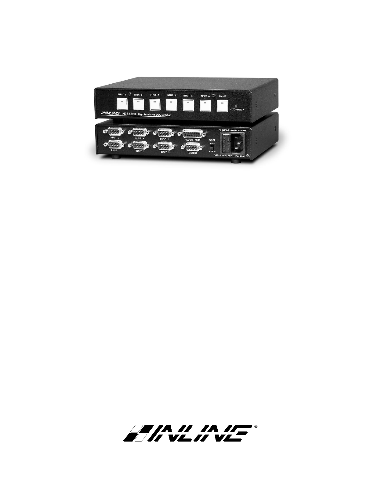
High Resolution VGA Switchers:
IN3564HR - 4 In 1 Out VGA Switcher
IN3566HR - 6 In 1 Out VGA Switcher
Page 2
Installation and Safety Instructions
For Models without a Power Switch:
The socket outlet shall be installed near the equipment and shall be accessible.
For Models with 110 / 220V Power Selector:
Caution: Before applying power to this unit, the voltage selector must be set to the appropriate setting to match local A/C line
voltage. Improper setting of the voltage selector may cause damage to the unit and create a potential fire hazard.
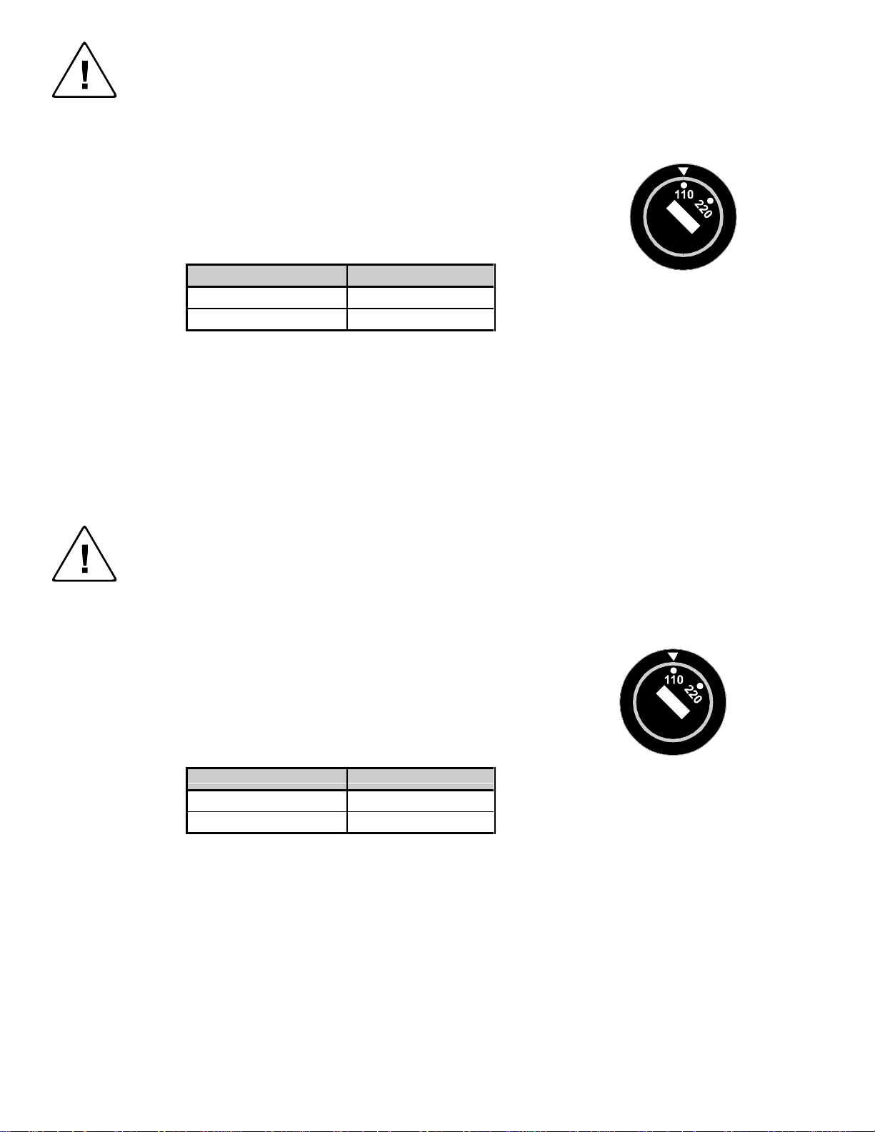
The voltage selector is a round switch located next to the A/C power input connector which looks
like this:
Using a straight slot screwdriver or small coin, rotate the selector to the correct position so that
the arrow lines up with 110 or 220 as appropriate for local power line voltage as indicated in the
chart below:
Local A/C Voltage Voltage Selector Setting
110 ~ 120 VAC 110
220 ~ 240 VAC 220
For all Models:
No serviceable parts inside the unit. Refer service to a qualified technician.
For Models with Internal or External Fuses:
For continued protection against fire hazard, replace only with same type and rating of fuse.
For IN2001 / IN3234 / IN3236 / IN3502 / IN3504 / IN3506 / IN3562 / IN3564 / IN3566 / IN3572 / IN3574 / IN3576:
Caution: Double pole / neutral fusing.
For all Models with Integral Lithium Battery:
Caution: Danger of explosion if battery is incorrectly replaced. Replace only with the same or equivalent type recommended by
the manufacturer. Dispose of used batteries according to the manufacturer’s instructions.
Instructions d’installation et de sécurité
Pour les modèles sans interrupteur de courant:
La prise de courant d’alimentation sera installé près de l’équipement et sera accessible.
Pour les modèles avec un sélecteur d’alimentation 110V/220V:
Attention: Avant de connecter l’appareil au circuit d’alimentation, le sélecteur de courant doit être positionné sur la sélection
appropriée correspondant au voltage du circuit de courant alternatif local. Une mauvaise sélection peut engendrer des
dommages à l’appareil et créer un danger d’incendie.
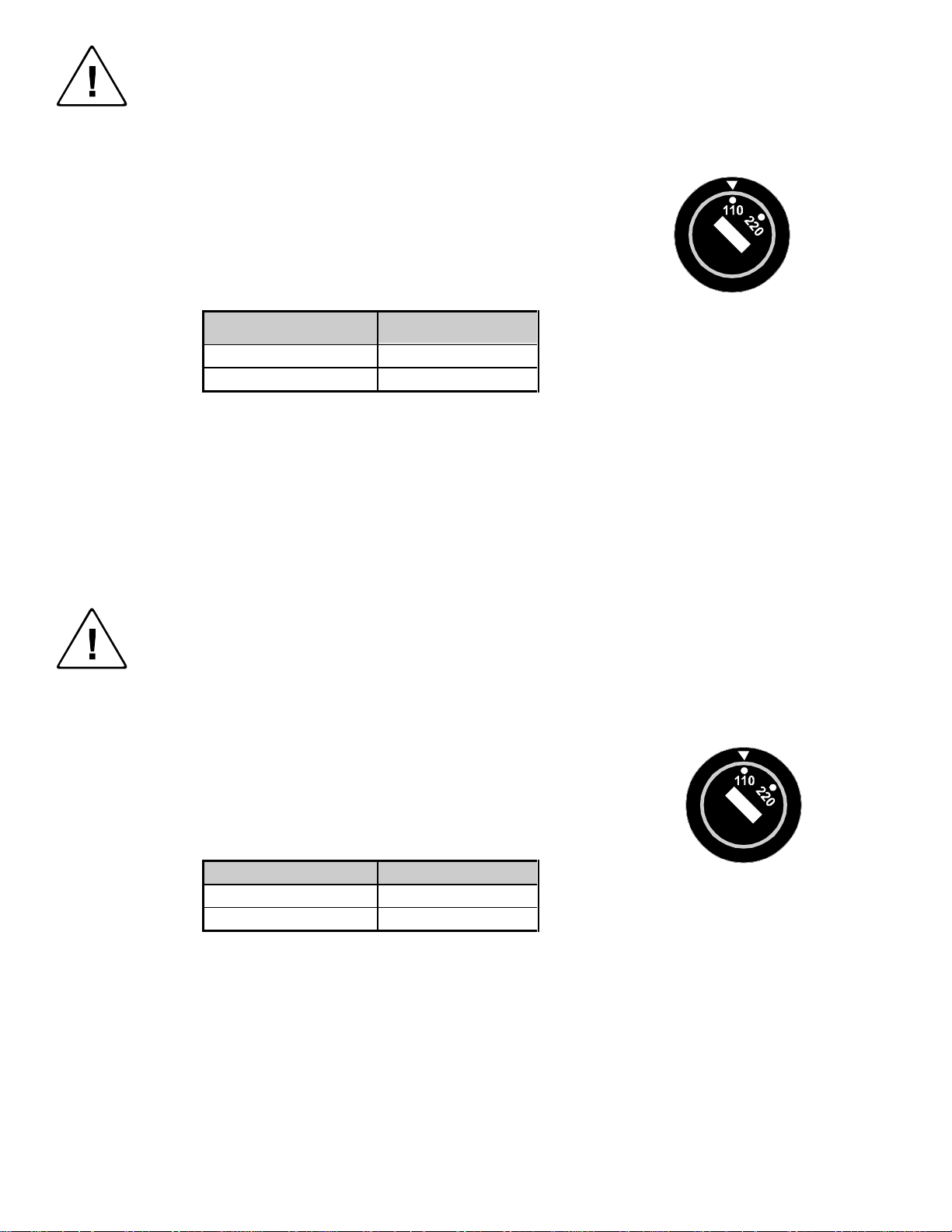
Le sélecteur d’alimentation est un commutateur rond positionné près du connecteur
d’alimentation. Il se représente comme suit:
A l’aide d’un tourne-vis plat ou d’une pièce de monnaie, le sélecteur peut être tourné dans la
position adéquate en veillaut que la flèche corresponde avec 110 ou 220, en fonction de la
valeur du circuit de courant local. (Voir tableau ci-dessous)
Circuit local AC Position Sélecteur
110 ~ 120 VAC 110
220 ~ 240 VAC 220
Pour tout les modèles:
Pas de composants à entretenir à l’intérieur. Confiez toute réparation à un technicien qualifié.
Pour les modèles équipés de fusibles internes ou externes:
Afin d’éviter tout danger d’incendie, ne remplacer qu’avec le même type et la même valeur de fusible.
Pour IN2001 / IN3234 / IN3236 / IN3502 / IN3504 / IN3506 / IN3562 / IN3564 / IN3566 / IN3572 / IN3574 / IN3576:
Attention: Double pôle / fusible au neutre.
Pour tout les modèles avec une batterie au lithium interne:
Attention: Danger d’explosion si la batterie est incorrectement remplacée. Ne remplacez la batterie qu’avec le même modèle,
ou avec un modèle recommandé par le constructeur. Traitez les batteries usagées selon les instructions du fabricant, ou selon
les normes écologiques en viguer.
Page 3
Installations und Sicherheitshinweise
Für Geräte ohne Netzschalter:
Die Netzsteckdose soll in de Nähe des Gerätes installiert und frei zugänglich sein.
Für Geräte mit 110 / 220V Spannungswähler:
Achtung: Bevor Sie dem Gerät Spann ung zuführen, muß der Spannungswähler entsprechend der Spannung des lokalen
Wechselspannungsnetzes eingestellt werden. Die falsche Stellung des Spannungswählers
kann eine Beschädigung des Gerätes und möglicherweise ein Feuer verursachen.
Der Spannungswähler ist ein runder Schalter in der Nähe der Netzeingangsbuchse mit
folgendem Aussehen:
Drehen Sie den Wähler mit einem normalen Schraubenzieher oder einer kleinen Münze so, daß
der Pfeil auf die 110 oder 220 zeigt, entsprechend der Spannung Ihr es lokalen Netzes wie hier
angezeigt:
Lokale Netzwechselspannung Stellung des
110 ~ 120 V 110
220 ~ 240 V 220
Für alle Geräte:
Keine Wartung innerhalb des Gerätes notwendig. Reparaturen nur durch einen Fachmann!
Für Geräte mit interner oder externer Sicherung:
Für dauernden Schutz gegen Feuergefahr darf die Sicherung nur gegen eine andere gleichen Typs und gleicher Nennleistung
ausgewechselt werden.
Für IN2001 / IN3234 / IN3236 / IN3502 / IN3504 / IN3506 / IN3562 / IN3564 / IN3566 / IN3572 / IN3574 / IN3576:
Achtung: Allpolige Absicherung
Für alle Geräte mit eingebauter Lithium Batterie:
Achtung: Explosionsgefahr bei falschem Batterieeinsatz. Batterie nur erstzen durch den gleichen oder entsprechenden Typ
wie vom Hersteller empfohlen. Entsorgung verbrauchter Batterien nur nach den Anweisungen des Herstellers.
Spannungswählers
Instalacion E Instrucciones de Seguridad
Modelos Sin Interruptor:
La conexión debe ser instalada cerca del equipo y debe ser accesible.
Modelos con Selector de Voltaje de 110/220V:
Precaución: Antes de operar esta unidad, el selector de voltaje debe instalarse de forma que corresponda a la linea de voltaje
local. Instalación inadecuada del selector de voltaje puede causar daño a la unidad y originar un incendio.
El selector de voltaje es un cambia vía redondo localizado cerca de la conexión electrica, como se
ve en el dibujo:
Use un destornillador comun o una moneda pequeña, mueva el selector a la posición correcta, de
forma que las flechas indiquen 110 o 220 de acuerdo con el voltaje local, como esta indicado a
continuación.
Voltaje Local A/C Selector de Voltaje
110 ~ 120 VAC 110
220 ~ 240 VAC 220
Para Todos Los Modelos:
Dentro de la unidad , no hay partes para reparar. Llame un tecnico calificado.
Modelos con Fusibles Internos o Externos:
Para prevenir un incendio, reemplace solo con el mismo tipo de fusible.
Modelos IN2001 / IN3234 / IN3236 / IN3502 / IN3504 / IN3506 / IN3562 / IN3564 / IN3566 / IN3572 / IN3574 / IN3576:
Precaución: Double Polo / Fusible Neutral.
Modelos con Bateria de Lithiun Interna:
Precaución: Peligro de explosión si la batería es reemplacada incorrectamente. Reemplace solamente con la misma clase de
batería, o una equivalente recomendada por el fabricante. Deseche las baterías usadas de acuerdo con las instrucciones del
fabricante.
Page 4
CE COMPLIANCE
All products exported to Europe by Inline, Inc. after January 1, 1997 have been
tested and found to comply with EU Council Directive 89/336/EEC. These
devices conform to the following standards:
EN50081-1 (1991), EN55022 (1987)
EN50082-1 (1992 and 1994), EN60950-92
Shielded interconnect cables must be employed with this equipment to
ensure compliance with the pertinent Electromagnetic Interference (EMI)
and Electromagnetic Compatibility (EMC) standards governing this device.
FCC COMPLIANCE
This device has been tested and found to comply with the limits for a Class A
digital device, pursuant to Part 15 of the FCC rules. These limits are designed to
provide against harmful interference when equipment is operated in a
commercial environment. This equipment generates, uses and can radiate radio
frequency energy and, if not installed and used in accordance with the instruction
manual, may cause harmful interference to radio communications. Operation of
equipment in a residential area is likely to cause harmful interference, in which
case the user will be required to correct the interference at their own expense.
Page 5

Product Overview
DESCRIPTION
The IN3564HR / IN3566HR is a high-performance video switcher that allow users to select
between four or six video sources and route the selected source to an attached video output device
such as a presentation monitor, video projector or desktop data monitor. Both models are
identical in function and design, with the only difference being the number of inputs:
The IN3564HR is a 4-input, 1-output VGA switcher.
The IN3566HR is a 6-input, 1-output VGA switcher.
The IN3564HR / IN3566HR switcher features a 350 MHz video bandwidth and is compatible
with VGA, SVGA, XGA, XGA2, UXGA and all other VGA signal resolutions and refresh rates.*
The switcher features five discrete signal paths per input, making it compatible with analog
signals in a variety of formats including RGBHV, RGBS, RGsB, RsGsBs and monochrome highresolution video. In addition, the IN3564HR / IN3566HR is also compatible with NTSC / PAL /
SECAM signals in component, Y/C or composite video formats.
1
The IN3564HR / IN3566HR is not a scan converter. The data
projector, monitor or other output device must be compatible with the
horizontal scan rates output by the computer video cards.
PRODUCT FEATURES
Two Switching Modes - In Manual Mode, users select the desired input by pressing a large
front panel input button or remotely via contact closure control. In Autoswitch Mode, the unit
automatically selects the active input. If more than one input is active, the highest numbered
input has priority. Autoswitching Mode is ideal for automatic operation in installations with
multiple interfaces or wall plates. The unit can be set for Manual or Autoswitch Mode using a
slider switch on the back panel of the switcher. A front panel LED illuminates to indicate that the
unit has been set to the Autoswitch Mode.
Front Panel Control - Users select the desired input by pressing a front panel button. Each time
a button is pressed, the switcher selects the appropriate input and an LED lights to indicate the
currently active port. All non-selected inputs are terminated to 75 ohms.
Rack Mountable Unit - Two units may be mounted side-by-side in a 1U rack space using the
optional IN9080 Rack Shelf (two or more switchers can work together as a large switching
system). A single unit may be rack-mounted using the IN9080 Rack Shelf and the IN9088 HalfRack Blank Plate. The switcher has a sleek black finish that blends well with other rack mounted
equipment, complementing the decor of boardrooms, training facilities, control rooms and other
high-tech / high profile installations featuring exposed equipment racks.
*Both units can also route video from Macintosh G3 and G4 models with 15-Pin HD connectors.
IN3564HR / IN3566HR Operation Manual - Prelim inary 7/30/99 © 1999 - INLINE Inc.
Page 6

2
15-Pin HD VGA Connectors - The IN3564HR / IN3566HR connects directly to VGA
computer graphics cards and VGA data displays using high-resolution coaxial VGA extension
cables such as the IN8000 Series. Input / output adapter cables (see table on page 6) are also
available in a variety of lengths for MAC (15-Pin D), SUN (13W3) and various workstations (4
or 5 BNC).
Stereo Audio-Follow-Video - capability may be achieved using an optional IN3546R Stereo
Audio Switcher in conjunction with the IN3564HR / IN3566HR. The IN3546R attaches to the
remote port, receiving both power and switching commands from the attached VGA switcher.
Remote Control - The Remote Port allows for remote input selection by any device that is
capable of providing momentary or latching contact closures. The remote port also includes a
+5V power supply and tally outputs to provide feedback to a control system. The IN3590 is an
optional hardwire remote control that connects directly to the port and provides remote channel
selection from up to 25’ away.
Blank Butto n - temporarily disconnects all video signals from the output when it is activated.
When the Blank Button is pressed again (deactivated), the switcher returns to the last selected
input.
Optional Input Label Plate – Two attachment posts are provided on the front panel above the
input selector buttons to securely hold the IN9348, an optional plastic plate that can be engraved
to indicate the name of each input source.
In addition, both units feature an Internal Universal Power Supply and Durable Metal Case
Enclosure. The IN3564HR / IN3566HR offers a flexible alternative for permanent installations,
staging systems, rentals and other applications requiring a compact, durable high-performance
video switcher.
Compatibility
IN3564HR / IN3566HR switcher features 15-pin HD female input and output connectors and
can switch five discreet signal components for each input. The IN3564HR / IN3566HR is
specifically designed to route several analog video signals including VGA, S-VGA, XGA, MAC,
Sun and other high-resolution workstations.
INPUT
The IN3564HR / IN3566HR will accept high-resolution video signals from virtually any
computer that outputs an analog video signal. The unit will work with signals at virtually any
resolution and refresh rate. Compatible signal formats include RGBHV, RGBS, RGsB,* RsGsBs
and Monochrome high-resolution video.
*The IN3564HR / IN3566HR will operate with RGsB input signals. However, the unit
will not strip sync off of the green. RGsB input signals are always output as RGsB (they
cannot be output as RGBS or RGBHV).
© 1999 - INLINE Inc. IN35 6 4H R / IN3566HR Operation Manual - Preliminary 7/30/99
Page 7

OUTPUT
The output signal of the IN3564HR / IN3566HR is analog RGB video with TTL sync on a 15-
pin HD VGA female connector. This output signal is compatible with high-resolution data grade
monitors and data / graphics projectors, making it ideal for use with LCD projectors and other
data display devices which require that all VGA sync formats and polarities remain unchanged
from the original source signal.
VGA high-resolution workstations operate in several video modes encompassing a wide
range of resolutions and scan rates. Many of the video signals from the newest models
can run as high as 70 KHz or more, with the newest VGA cards offering an output
resolution of 1600 x 1200 (some can even go as high as 1920 x 1080). The data
projector or monitor connected to the switcher output must be compatible with the
horizontal scan rate and vertical refresh rate of the computer’s video signal. Please
check the documentation for both the computer graphics card and the data display
device to ensure compatibility.
3
Installation
This section offers step-by-step instructions for connecting / installing the IN3564HR /
IN3566HR Switcher. A detailed application drawing showing all equipment connections is
included on page 4.
1. Units mounted in a 1U rack should be installed before making any connections. Multiple
units must first be installed in an IN9080 Rack Shelf. Single units can be mounted in the
rack shelf with an IN9088 Half-Rack Blank Plate.
2. Connect all VGA sources to the IN3564HR / IN3566HR input connectors.* Unused inputs
do not need to be terminated.
3. Connect the display device to the output of the IN3564HR / IN3566HR.
Cable selection is critical to overall system performance, especially when
dealing with very high scan rates and / or long cable runs. High-resolution
VGA extension cables such as the IN8000 Series are recommended for all
input and output connections.
4. Apply AC Power to the unit (the unit powers up automatically).
5. Select the appropriate switching mode. The mode switch on the back of the IN3564HR /
IN3566HR is used to select between auto and manual. The LED on the front of the switcher
indicates when the unit is in auto switch mode. By applying the optional IN3590 Remote
Control, the user will override the mode switch.
* A 1 x 2 distribution amplifier (such as an IN3262D / IN3262DS) may be required at one or more of
the input devices in order to split off a signal for local monitors and / or amplify the signal to
compensate for long cable runs. For applications that require cable runs in excess of 300’, users may
wish to employ the IN1110 / IN1111 Video Transmitter / Receiver System to improve signal quality.
IN3564HR / IN3566HR Operation Manual - Prelim inary 7/30/99 © 1999 - INLINE Inc.
Page 8

4
IN3564HR / IN3566HR APPLICATION DIAGRAM
FUSE; 8 A; 250 V; TIME DELAY
Control System
REMOTE PORT
VGA Port
Laptop with
INPUT 6
125 VAC; 6.4 A; 47-63 HZ
Cable
IN9045/IN8000
Data Projector/
Present at ion Monitor
OUTPUT
INPUT 5
CPU with
VGA Port
VGA Port
Laptop with
VGA Port
Laptop with
IN8000 series
VGA Ex ten sion C able
INPUT 4
INPUT 2
INPUT 3
INPUT 1
IN8000 series
VGA Ext ens ion C abl e
© 1999 - INLINE Inc. IN35 6 4H R / IN3566HR Operation Manual - Preliminary 7/30/99
CPU with
VGA Port
CPU with
VGA Port
Page 9

OPERATION
The IN3564HR / IN3566HR Switcher features Auto Power On, so the unit powers up automatically
when A/C power is applied. The IN3564HR and IN3566HR Switchers provide four and six front
panel buttons (respectively) which, when in Manual Mode, may be used to select the desired input
channels. Input one is automatically selected at power up. In order to select a different input, press
the corresponding input button and the appropriate LED will light to indicate the current active
channel.
When the Autoswitch Mode is selected (switch is located on the back of the unit), the unit will
automatically select the active input. If the switcher is connected to more than one input, the
Autoswitch Mode will automatically select the highest input (Example: Input three will supercede
inputs one and two, providing that the rest of the inputs are unterminated).
All non-selected channels are terminated to 75 ohms. The output signal may be blanked (no input
selected) by pressing the Blank Button on the front of the unit. Input channels may also be selected
remotely by using the optional IN3950 hardwired remote control.
Since these switchers are passive they are also bi-directional, meaning that signals may pass both
ways through the unit. In such an installation, a single source signal is run through the output
connector and multiple display devices are attached to the input receptacles. The source signal is
routed to the attached display device whose input switch is selected.
5
REMOTE CONTROL OPERATION
The IN3564HR / IN3566HR Switcher has a Remote Port located on the back of the unit. Channels
can be selected through the Remote Port by providing contact closures between the appropriate pins.
The port also includes a +5V power supply and tally outputs. Several contact closure type control
devices are available including:
• IN3590 - An optional hard-wired remote designed to work with all IN3500 Series
switchers.
• IN6901 / IN6902 RS-232 to Contact Closure Converter - allows IN3500 Series
switchers and other INLINE devices with contact closure control ports to be controlled
by RS-232 sources such as control systems and computer serial ports.
• Control Systems - many control systems are capable of providing contact closures.
Control Parameters - In order to select a channel, the channel select pin (pins 1 - 6) must connected
to Common (pin 7 or 8). The contact closures may be momentary or continuous (Example: To switch
to input channel 4, apply a contact closure between pin 4 and pin 7). If two channels are selected
simultaneously, the output of the switcher is blanked (no output is selected). In order to maintain
blanking, these two closures must be continuous.
Tally Output - The remote control port also provides Tally Outputs (pins 10-15) which may be used
to trigger other devices, provide feedback to a control system or light indicator lights on a custom
remote control panel. When a channel is selected, either from the front panel or through the remote
control port, the Tally Output for that channel is switched on. The Tally Output can switch voltages
of up to 50 volts and current up to 1.5 amps.
IN3564HR / IN3566HR Operation Manual - Prelim inary 7/30/99 © 1999 - INLINE Inc.
Page 10

6
Control Port Pin Outs - The Remote Control port is a female 15-pin D connector with the following
pin outs:
Pin 1 - Select Channel 1 Pin 6 - Select Channel 6* Pin 11 - Tally Output for Channel 5*
Pin 2 - Select C hannel 2 Pin 7 - Common
Pin 3 - Select Channel 3 Pin 8 - Common Pin 13 - Tally Output for Channel 3
Pin 4 - Select Channel 4 Pin 9 - +5 Volts DC Pin 14 - Tally Output for Channel 2
Pin 5 - Select Channel 5*
Pin 10 - Tally Output for Channel 6* Pin 15 - Tally Output for Channel 1
IN3546R STEREO AUDIO SWITCHER
The IN3546R Stereo Audio Switcher may be attached to the IN3564HR / IN3566HR via the Remote
Control Port. This provides a +5V power supply for the IN3546 Switcher and a control link. When
the audio switcher is attached to the control port using an IN9112 / IN9133 Control / Power cable, the
IN3546R will automatically switch to the appropriate input channel, mirroring the input selection on
the attached IN3564HR / IN3566HR and adding audio-follow-video capability to the switcher.
ADAPTER / EXTENSION CABLES FOR INPUT AND LOCAL MONITOR OUTPUT
The IN3564 HR / IN3566HR has 15-pin HD VGA-type connectors for input and local monitor
output. The following input and local monitor output cables are available:
Pin 12 - Tally Output for Channel 4
* Used only on IN3566HR
Computer 3’ 6’ 12’ 25’
VGA: 15-Pin HD
Input Cable
Output Cable
MAC with 15-Pin D:
Input Cable
Output Cable
MAC G3, G4 and PowerBook with 15-Pin HD*:
Input Cable
Output Cable
Sun: 13W3 (may also be used with SGI with RGsB output)
Input Cable
Output Cable
Workstation: 5 BNC / RGBHV
Input Cable
Output Cable
Workstation: 4 BNC / RGBS
Input Cable
*Newer Mac G3 models (with translucent cases) have 15-Pin HD connectors (pins arranged in 3 rows).
Older G3 models (with solid white enclosures) incorporate 15-Pin D connectors (pins arranged in 2 rows).
IN9141 IN9145
IN9143 IN9147
IN8006M IN8012M IN8025M
IN8006 IN8012 IN8025
IN9140M IN9144M
IN8006M IN8012M IN8025M
IN8006 IN8012 IN8025
IN9142M IN9146M
IN9047 IN9045 IN9045-L25
IN9047 IN9045 IN9046-L25
IN9100M
© 1999 - INLINE Inc. IN35 6 4H R / IN3566HR Operation Manual - Preliminary 7/30/99
Page 11

Specifications
IN3564HR IN3566HR
Inputs
Connector Type 15-pin HD VGA female
Number of Inputs 4 6
Signal Components per Input 5
RGB Video Signals Analog Video, 0.7 Vp-p nom. 1.5 Vp-p max.
Input Impedance 75 ohms
Sync Signals TTL compatible, 5Vp-p max.
Signal Compatibility
Output
Connector Type 15-pin HD VGA female
Output Sync Formats RGBHV, RGBS and RGsB
RGB Signals Analog Video, 75 ohm impedance
Bandwidth 350 MHz @ -3 dB
Isolation
Remote Port 15-Pin D female connector
Switching Time 2.0 mSec typical
Power
Power Supply Internal switching mode: 90-260 VAC; 47-63 Hz
Voltage 110 / 220 (set at factory)
Consumption 8 watts
Dimensions
Size 1.65” H x 8.5” W x 6” D / 4.2cm x 21.6cm x 15.2cm
Shipping Weight 3 lbs. / 1.5 kgs.
Regulatory Compliance
Safety
EMI
FCC class A; CE: EN50022 (1987), EN50081-1
(1991), EN50082-1 (1992 & 1994), EN60950-92
RGBHV, RGBS, RGsB
& High-Resolution Monochrome
60 dB @ 50 MHz / 55 dB @
75 MHz / 50 dB @ 100 MHz
rd
UL 1950. 3
CAN/CSA-22.2 No. 950 3
Ed.; CE: EN50081-1
rd
Ed.
7
Parts Included
(1) IN3564HR or IN3566HR VGA Switcher
(1) IN9230 IEC Power Cable, 6’ long (USA only)
(1) Operations Manual
IN3564HR / IN3566HR Operation Manual - Prelim inary 7/30/99 © 1999 - INLINE Inc.
Page 12

8
Required Accessories (Ordered Separately)
Input / Output Adapter and Extension Cables
VGA: IN8000 Series 15-pin HD (male to male), available in various lengths from 3’ to 100’
For other Computers: See list on page 6
Optional Accessories
Remote Equipment
IN3590 - Hand held wired remote control
IN6901 / IN6902 - RS-232 to Contact Closure Converter
Powered Accessories
IN1110 / IN1111 - Video Transmitter / Receiver System
IN3262D / IN3262DS - Distribution Amplifier
IN3546R - 6-Input, 1-Output Stereo Audio Switcher
IN9112 - Control / Power cable for IN3546R
IN9133 - Control / Power cable for IN3546R with loop-through
Installation Hardware
IN9080 - Rack Shelf
IN9088 - Half-Rack Blank Plate
IN9348 - Engraveable Plastic Input Labeling Plate
Troubleshooting
The display device connected to the IN3564HR / IN3566HR output has a bad / scrambled
image.
Solution 1: Verify that the correct input cable is being used.
Solution 2: The display device connected to the output of the interface may not be compatible
with the computer output. Standard 640 x 480 VGA runs at 31.5 KHz, but SVGA
can be as high as 48 - 58 KHz depending on the vertical refresh rate. Many
workstations have new ultra high-resolution modes such as 1600 x 1200 and 1800 x
1440 and can output a video signal with a horizontal scan rate of over 100 KHz!
Many data monitors and data projectors are not compatible with these resolutions and
frequencies.
The unit does not pass any signals.
Solution: The IN3564HR / IN3566HR contains two internal fuses. If power is applied to the
unit and none of the front panel LEDs activate, these fuses may be blown. Open the
case as described below and replace the blown fuses with new 200mA fuses.
1. Disconnect power to the switcher
2. Unscrew the two screws on each side of the unit
3. Gently slide off the top cover
4. Replace the bad fuse(s)
5. Replace the top cover and tighten the screws
© 1999 - INLINE Inc. IN35 6 4H R / IN3566HR Operation Manual - Preliminary 7/30/99
Page 13

When controlling the IN3564HR / IN3566HR Switcher through the REMOTE CONTROL
port, the image is blanked and no channel is being selected.
Solution: The control system may be closing two contacts at the same time. Check the wiring
on the control cable and the control system programming.
If problems persist, call INLINE Technical Services at (800) 882-7117 for further assistance.
Warranty
9
♦
♦
♦
♦
INLINE warrants the equipment it manufactures to be free from defects in
materials and workmanship.
If equipment fails because of such defects and INLINE is notified within two (2)
years from the date of shipment, INLINE will, at its option, repair or replace the
equipment at its plant, provided that the equipment has not been subjected to
mechanical, electrical, or other abuse or modifications.
Equipment that fails under conditions other than those covered will be repaired at
the current price of parts and labor in effect at the time of repair. Such repairs are
warranted for ninety (90) days from the day of re-shipment to the Buyer.
This warranty is in lieu of all other warranties expressed or implied,
including without limitation, any implied warranty or merchantability or
fitness for any particular purpose, all of which are expressly disclaimed.
The information in this manual has been carefully checked and is believed to be accurate. However,
INLINE, Inc. assumes no responsibility for any inaccuracies that may be con tained in this manual. In
no event will INLINE, Inc. be liable for direct, indirect, special, incidental, or consequential damages
resulting from any defect or omission in this manual, even if advised of the possibility of such
damages. The technical information contained herein regarding IN35 64HR / IN3566HR features and
specifications is subject to change without notice.
IBM is a registered trademark of International Business Machines. Macintosh is a registered
trademark of Apple Comput ers, Inc. All other trademarks an d registered trademarks are th e property
of their respective companies.
All Rights Reserved © Copyright 1999
INLINE, INC. ♦ 810 West Taft ♦ Orange, CA 92865
(800) 882-7117 ♦ (714) 450-1800 ♦ FAX (714) 450-1850 ♦ www.inlineinc.com
IN3564HR / IN3566HR Operation Manual - Preliminary 7/30/99 © 1999 - INLINE Inc.
 Loading...