

Page 1
Operation Manual
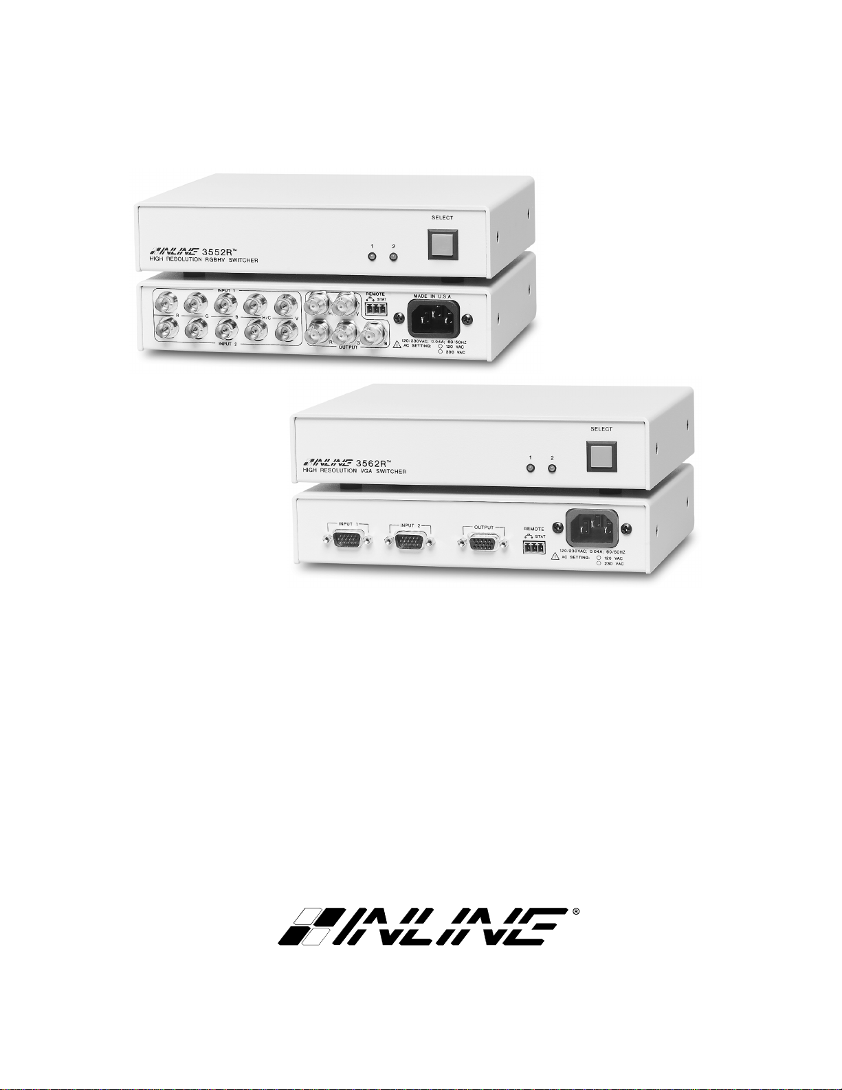
2-Input, 1-Output Switcher Series:
IN3552R - RGBHV Switcher
IN3562R - VGA Switcher
Page 2

Installation and Safety Instructions
For Models without a Power Switch:
The socket outlet shall be installed near the equipment and shall be accessible.
For all Models:
No serviceable parts inside the unit. Refer service to a qualified technician.
For Models with Internal or External Fuses:
For continued protection against fire hazard, replace only with same type and rating of fuse.
Instructions d’installation et de sécurité
Pour les modèles sans interrupteur de courant:
La prise de courant d’alimentation sera installé près de l’équipement et sera accessible.
Pour tout les modèles:
Pas de composants à entretenir à l’intérieur. Confiez toute réparation à un technicien qualifié.
Pour les modèles équipés de fusibles internes ou externes:
Afin d’éviter tout danger d’incendie, ne remplacer qu’avec le même type et la même valeur de fusible.
Installations- und Sicherheitshinweise
Für Geräte ohne Netzschalter:
Die Netzsteckdose soll in der Nähe des Gerätes installiert und frei zugänglich sein.
Für alle Geräte:
Keine Wartung innerhalb des Gerätes notwendig. Reparaturen nur durch einen Fachmann!
Für Geräte mit interner oder externer Sicherung:
Für dauernden Schutz gegen Feuergefahr darf die Sicherung nur gegen eine andere gleichen Typs und gleicher Nennleistung
ausgewechselt werden.
Instalacion E Instrucciones de Seguridad
Modelos Sin Interruptor:
Para Todos Los Modelos:
Modelos con Fusibles Internos o Externos:
La conexión debe ser instalada cerca del equipo y debe ser accesible.
Dentro de la unidad , no hay partes para reparar. Llame un tecnico calificado.
Para prevenir un incendio, reemplace solo con el mismo tipo de fusible.
CE COMPLIANCE
All products exported to Europe by Inline, Inc. after January 1, 1997 have been tested and found to
comply with EU Council Directive 89/336/EEC. These devices conform to the following
standards:
EN50081-1 (1991), EN55022 (1987)
EN50082-1 (1992 and 1994), EN60950-92
Shielded interconnect cables must be employed with this equipment to ensure compliance with
the pertinent Electromagnetic Interference (EMI) and Electromagnetic Compatibility (EMC)
standards governing this device.
FCC COMPLIANCE
This device has been tested and found to comply with the limits for a Class A digital device,
pursuant to Part 15 of the FCC rules. These limits are designed to provide against harmful
interference when equipment is operated in a commercial environment. This equipment generates,
uses and can radiate radio frequency energy and, if not installed and used in accordance with th e
instruction manual, may cause harmful interference to radio communications. Operation of
equipment in a residential area is likely to cause harmful interference, in which case the user will be
required to correct the interference at their own expen s e.
Page 3

DESCRIPTION
The IN3552R and IN3562R are high performance analog video switchers featuring two inputs and one
output. These switchers are designed to route high resolution source signals to an attached video
projector, monitor, LCD panel or color printer. Users may select the desired input channel using the
front panel channel select button or via remote control by using a wired remote, third-party control
system, or any other device capable of providing a latching contact closure. The IN3552R / IN3562R
switchers offer easy operation and the following features:
♦ 650 MHz or 500 MHz Video Bandwidth – high performance units route ultra-high resolution video
signals with no signal loss
♦ Passive Design - ensures compatibility with a wide range of video and audio signals
♦ Front Panel Channel Selection Button and LED Indicators
♦ Remote Port - allows for remote selection of input channel using contact closure. A status pin
provides feedback to a control system to indicate which input is currently selected.
♦ Monitor Emulation Switches (IN3562R only) - for Input 1 and Input 2 can provide VGA or MAC
monitor emulation for applications where a computer graphics card is connected directly to the
switcher input.
♦ Rack Mountable – Units rack mount in a 1U rack space using the optional IN9080 rack shelf. Two
units will mount side-by-side on a single rack shelf. A single unit may be rack-mounted by using the
IN9080 Rack Shelf plus an IN9088 Blank Panel.
1
COMPATIBILITY
The IN3552R and IN3562R switchers are passive devices which will switch a wide variety of signals.
While the units were primarily designed for use with high resolution RGB analog computer graphics type
signals, they may also be used to switch Composite Video, S-Video (Y/C), Component Video, or audio
signals. The IN3552R and IN3562R function very similarly, utilizing the same front control panel and
switching circuitry. The main difference between the various models is the type of input/output
connectors on the back panel and the number of discrete signal components for each input.
IN3552R RGBHV Analog Video Switcher - is a two input, one output switcher featuring a set of five
BNCs for each input and output connection. The unit can switch five discrete signal components for
each input and is compatible with analog computer video signals in any of the following formats:
RGBHV, RGBS, RGsB, RsGsBs, and composite monochrome with sync. Since the IN3552R switches
five discrete signal components simultaneously, it may also be employed as audio-follow-video switcher
when used with composite, Y/C, component or RGBS signals.
IN3562R VGA Switcher - is a two input, one output switcher featuring 15-pin HD connectors for input
and output connection. The IN3562R connects directly to VGA, S-VGA, and XGA computer graphics
cards and monitors using standard 15-HD VGA extension cables. For applications where the computer
graphics card will be connected directly to the switcher, monitor emulation dip switches are available
which can emulate a VGA or MAC monitor (see page 5). The IN3562R has six discrete signal paths for
six signal components and may be used with analog video signals in any of the following formats:
RGBHVS, RGBHV, RGBS, RGsB, RsGsBs, and composite monochrome with sync. The switcher can
be connected to MAC, SUN, SGI and 4 or 5 BNC workstations using input / output adapter cables, which
are available in a variety of lengths (see list on page 2).
© 2001 - INLINE, INC. IN3552R / IN3562R OPERATION MANUAL - REV. 1.1 11/16/01
Page 4

2
INSTALLATION
This section offers step-by-step instructions for installing IN3552R / IN3562R switchers. A detailed
application drawing showing all equipment connections is shown on the next page.
1. Connect both sources to the IN3552R / IN3562R input connectors.
IN3552R: An interface may be required for each computer video signal source in order to split
off a signal for each local monitor, bring all signals into the RGBHV format, and amplify the
signal to compensate for long input/output cable runs.
IN3562R: A 1x2 distribution amplifier (IN3262 / IN3262D) may be required at each computer
in order to split off a signal for each the computer’s local monitor, provide monitor emulation and
amplify the signal to compensate for long input/output cable runs. If the computer video outputs
are being connected directly to the switcher inputs, it may be necessary to set the IN3562R input
termination switches to emulate a VGA or MAC monitor. Information on these dip switches is
silk screened on the bottom of the unit and can also be found on page 5.
2. Connect the IN3552R / IN3562R output to the display device.
3. Apply AC power to the unit.
It is very important that all input / output connections be made utilizing high resolution
coaxial cables. Proper cable selection is critical to overall system performance,
especially when working with high frequency signals and/or long cable runs. The
following cables are recommended for use with the IN3552R / IN3562R switchers.
IN3552R: Use IN7000-5, IN7100-5, IN7200-5, IN7300-5 Series - 5 Conductor Cables,
available in a variety of lengths from 6’ to 250’, terminated with male BNC connectors.
IN3562R with VGA, MAC, SUN, SGI, 4&5-BNC computer graphics cards, monitors and
data displays: Use the input / output adapter cables as indicated in the chart below.
IN3562R INPUT / OUTPUT ADAPTER AND EXTENSION CABLES
VGA MAC SUN (13W3 - RGBS) SGI (13W3 RGsB) 5-BNC (RGBHV/RGBS/RGsB )
Input Cables 6’ Long IN8006 IN9140 IN9142 IN9148 IN9048
12’ Long IN8012 IN9046
25’ Long IN8025 IN9144 IN9146 IN9150 IN9046-L25
50' to 250' IN8000 Series IN9046-Lxx
Output Cables 3' Long N/A IN9141 IN9143 IN9149
6’ Long IN8006 IN9047
12’ Long IN8012 IN9045
25’ Long IN8025 IN9145 IN9147 IN9156 IN9045-L25
50' to 250' IN8000 Series
IN9045-Lxx
IN3552R / IN3562R OPERATION MANUAL - REV. 1.1 11/16/01 ©2001 - INLINE, INC.
Page 5

Local
Monitor
Application Diagram - IN3562R
IN3262 / IN3262D
OUTPUT 1
PC with
VGA Out
IN3562R
INPUT
®
3262
HIGH RESOLUTION
VGA DISTRIBUTION AMPLIFIER
INPUT 1
OUTPUT 2
IN8000 Series
VGA Cables
INPUT 2
OUTPUT
IN8000 Series
VGA Cable
Data Projector /
Data Monitor
REMOTE
STAT
120/230VAC; 0.04A; 60/50 HZ
AC SETTING:
Power Source
120 VAC
230 VAC
AC
Local
Monitor
PC with
VGA Out
IN3262 / IN3262D
OUTPUT 1
INPUT
3262
HIGH RESOLUTION
VGA DISTRIBUTION AMPLIFIER
OUTPUT 2
®
Page 6

4
OPERATION
Input Selection
The IN3552R / IN3562R two input switchers provide a front panel button which may be used to select
the desired input channel. Each time the SELECT button is pressed the unit toggles back and forth
between Input 1 and Input 2 and the appropriate front panel LED indicator lights to show the current
channel selection. The non-selected channel is terminated into 75 Ohms. The switcher automatically
returns to the last selected channel if power is removed and reapplied to the unit. Input channels may also
be selected remotely by using a wired remote or a third-party control system (see Remote Control
Operation below for more details).
Since the IN3552R / IN3562R switchers are passive, they are also bi-directional, meaning that signals
may pass backwards through the unit. In such an installation, a single source signal is hooked up to the
OUTPUT connector and two display devices are attached to the INPUT connectors. When an input is
selected, the source signal is routed to one of the attached display devices.
REMOTE CONTROL OPERATION
PIN
FUNCTION
1 Input Select
2 Ground
3 Status
The IN3552R / IN3562R switchers have a REMOTE port, a 3-pin captive screw connector which allows
the units to be remotely controlled and also provides feedback to indicate which input is currently
selected. Input 1 or Input 2 can be selected through the remote port by providing a latching contact
closure between the pin 1 and pin 2 on the REMOTE jack. Opening or closing the contact closure on the
REMOTE jack causes the unit to select the opposite input. The front panel switch and the contact
closure switch work independently. Therefore, an open or closed status between pins 1&2 on the
REMOTE port could select either Input 1 or Input 2 depending on the current position of the front panel
switch as indicated in the chart below.
Front Panel Button - Out
Front Panel Button - Depressed
Pin 1 & Pin 2 - No Connection Pin 1 Grounded to Pin 2
Input 2 Selected Input 1 Selected
Input 1 Selected Input 2 Selected
Status Pin (Pin 3) -
The REMOTE connector status pin can be used to provide feedback to a control system to indicate
whether Input 1 or Input 2 is currently selected. The status pin will be high or low depending on the
current input:
Pin 3 High (5V) - Input 2 is currently selected
Pin 3 Low (0V) - Input 1 is currently selected
IN3552R / IN3562R OPERATION MANUAL - REV. 1.1 11/16/01 ©2001 - INLINE, INC.
Page 7

Contact Closure Devices
Any device capable of providing a latching contact closure may be used to control the IN3552R /
IN3562R. Several contact closure type control devices are available:
IN6901 / IN6902 RS-232 to Contact Closure Converters - allow IN3500 Series switchers and
other INLINE devices with contact closure control ports to be controlled by RS-232 sources such
as control systems and computer serial ports.
Control System - many control systems are capable of providing contact closures.
Remote Control Panel - a custom remote panel or remote switch may be fabricated by the
installer.
Disable Front Panel Input Selector
The front panel input selector can be disabled for applications where the switcher will only be controlled
through the remote port. To disable or enable the front panel input selector, set Jumper 7 (located inside
the unit) as follows:
J7 Open: Front Panel Input Selector Enabled (factory default)
J7 Closed: Front Panel Input Selector Disabled
In order to set Jumper 7, the IN3552R / IN3562R case must be opened. The procedure
for opening the case and location of jumper 7 are indicated on page 6. This procedure
should only be done by a qualified technician in a static-free environment. Failure to
follow proper procedures could result in damage to the unit or electric shock.
When the front panel selector is disabled, the remote port always functions in the following manner (it
makes no difference how the front panel selector is set):
Pins 1 and 2 open: Input 2 Selected
Pin 1 grounded to Pin 2: Input 1 Selected
5
MONITOR EMULATION (IN3562R ONLY)
Some computer graphics cards must be connected to a local monitor in order to output a signal or select
an appropriate resolution. In order to ensure proper initialization of the graphics card at computer boot
up, a local monitor should be connected to each computer. If that is not practical, then the IN3562R
monitor emulation dip switches (located on the bottom of the switcher) should be set to the appropriate
settings for each input as indicated in the chart below.
Monitor Emulation Input 1 Input 2
VGA Color Monitor Dipswitch 1 - On Dipswitch 4 - On
Apple 13/14" RGB Monitor Dipswitch 1 - On Dipswitch 4 - On
Apple 2-Page Mono Dipswitch 3 - On Dipswitch 6 - On
Apple Portrait Monitor Dipswitch 2 & 3 - On Dipswitch 5 & 6 - On
Apple 21s Color Monitor Dipswitch 1, 2 & 3 - On Dipswitch 4, 5 & 6 - On
When using a multiscan or other MAC monitor not shown in the chart with most newer Apple Macintosh
computers, the Apple 13"/14" RGB monitor emulation settings will initialize the video card. The desired
resolution may then be selected using the Chooser menu.
© 2001 - INLINE, INC. IN3552R / IN3562R OPERATION MANUAL - REV. 1.1 11/16/01
Page 8

6
Fuse F1
INTERNAL FUSES
The IN3552R / IN3562R switchers contain two internal fuses. If power is applied to the unit and neither
of the front panel LEDs is illuminated, these fuses may be blown. Open the case as described below,
locate the two fuses as indicated in the diagram below and replace blown fuses as required with new
200mA / 250V fuses.
J7
C1
Fuse F2
Caution: The case opening procedure should only be done by a qualified technician in a static-free
environment. Failure to follow proper procedures could result in damage to the unit or electric shock.
Case Opening Procedure:
1. Remove power from the unit.
2. Loosen and remove the four case screws on the sides of the unit.
3. Lift off the top half of the IN3552R / IN3562R case. Capacitor C1 may store an electrical charge
even when the unit is powered down. Take care not to touch this component.
Case Closing Procedure:
Replace the top case and tighten the four case screws.
IN3552R / IN3562R OPERATION MANUAL - REV. 1.1 11/16/01 ©2001 - INLINE, INC.
Page 9

SPECIFICATIONS
IN3552R
RGBHV Switcher
7
IN3562R
VGA Switcher
Inputs
Connector type
Number of Inputs
Maximum Signal
Components per Input
Signal Compatibility
Output
Connector type
Bandwidth
Isolation
Switching Time
Power
Voltage
Consumption
5 BNC Female 15 Pin HD Male
2 Inputs
5
RGBHV, RGBS, RGsB, RsGsBs,
Monochrome with Sync, Composite Video,
Y/C, Component Video, Audio
Monochrome with Sync, Composite Video,
RGBS, RGsB, RsGsBs ,
RGBHV, RGBHVS
Y/C, Component Video, Audio
5 BNC Female
15 Pin HD Female
650 MHz
.7Vp-p input signal @ - 3dB
.7Vp-p input signal @ - 3dB
60 dB @ 50 MHz 55 dB @ 75 MHz 50 dB @ 100 MHz
2.5 mSec Typical
120/230 VAC; 60/50 Hz - Set at Factory
10 Watts
2 Inputs
6
500 MHz
Dimensions
Size
Product Weight
Shipping Weight
Regulatory Approval
Safety
EMI / ESD
Height: 1.65" / 4.2cm Width: 8.5" / 21.6cm Depth: 6" / 15.2cm
2.2 lbs. / 1.0 Kg
4 lbs. / 2 Kg
UL 1950, 3rd Ed.; CE: EN60950-92;
CAN/CSA-22.2 No. 950 3
rd
Ed.
FCC class A; CE: EN50081-1,
EN55022, EN50082-1
© 2001 - INLINE, INC. IN3552R / IN3562R OPERATION MANUAL - REV. 1.1 11/16/01
Page 10

8
Parts Included
AC Power Cable (U.S. Only)
Operations Manual
IN3552R IN3562R
AC Power Cable (U.S. Only)
Operations Manual
Optional Accessories
Rack Mounting Equipment IN9080 Rack Shelf – Holds Two Units Side-By-Side
IN9088 Blank Panel – Fills empty space when using IN9080 Rack Shelf with
only one IN3552R or IN3562R switcher.
TROUBLESHOOTING
The display device connected to the switcher output has a bad/scrambled image.
Solution 1: The display device connected to the output of the switcher may not be compatible with the
computer’s video output. VGA / SVGA / XGA / SXGA graphics cards operate at multiple
resolutions and refresh rates with newer modes such as 1920 x 1400 running as high as
79KHz! Check the operation manual on both the computer graphics card and the display
device to ensure that they are compatible.
Solution 2: The RGB, VGA, or MAC input or output cable may have a bad sync line. Try running the
sync through another cable.
The unit does not pass any signals.
Solution: Verify that the unit is getting power by checking the front LEDs. If no LED is on, the AC
power source may be faulty or the unit may have an internal problem. Check the two internal
200mA fuses (see Page 6).
When controlling the switcher through the REMOTE CONTROL port, Input 2 can be
selected for an instant, but then the unit quickly switches back to Input 1.
Solution: The control system may be providing a momentary contact closure. The IN3552R/IN3562R
require a latching closure to select Input channel 2.
When hooking a MAC Quadra computer directly to the IN3562R input, the computer is
booting up in the 13" RGB monitor resolution (640 X 480). How can the computer be
forced to boot in the 21" mode?
Solution: Use an IN2076 distribution amplifier to split the signal between the local monitor and the
switcher input. The computer will see the 21" local monitor attached to the IN2076 loopthrough connector and will boot up in that high resolution mode.
IN3552R / IN3562R OPERATION MANUAL - REV. 1.1 11/16/01 ©2001 - INLINE, INC.
Page 11

WARRANTY
♦
INLINE warrants the equipment it manufactures to be free from defects in materials and
workmanship.
♦
If equipment fails because of such defects and INLINE is notified within three (3) years from the
date of shipment, INLINE will, at its option, repair or replace the equipment at its plant, provided
that the equipment has not been subjected to mechanical, electrical, or other abuse or
modifications.
♦
Equipment that fails under conditions other than those covered will be repaired at the current
price of parts and labor in effect at the time of repair. Such repairs are warranted for ninety (90)
days from the day of re-shipment to the Buyer.
♦
This warranty is in lieu of all other warranties expressed or implied, including without
limitation, any implied warranty or merchantibility or fitness for any particular purpose,
all of which are expressly disclaimed.
The information in this manual has been carefully checked and is believed to be accurate. However,
Inline, Inc. assumes no responsibility for any inaccuracies that may be con tained in this manual. In no event will
Inline, Inc. be liable for direct, indirect, special, incidental, or consequential damages resulting from any defect
or omission in this manual, even if advised of the possibility of such damages. The technical information
contained herein regarding IN3552R / IN3562R features and specifications is subject to change without notice.
IBM is a registered trademark of International Business Machines. Apple, MAC, Quad ra, Centris, Performa, and
Powerbook are registered trademarks of Apple Computers, Inc. All other trademarks and registered trademarks
are the property of their respective compan ies.
© Copyright 2001 - Inline, Inc. All Rights Reserved
9
© INLINE, INC.
800-882-7117 ♦ 714-450-1800 ♦ FAX 714-450-1850 ♦ www.inlineinc.com
♦
810 WEST TAFT ♦ ORANGE, CA 92865
© 2001 - INLINE, INC. IN3552R / IN3562R OPERATION MANUAL - REV. 1.1 11/16/01
 Loading...