

Page 1
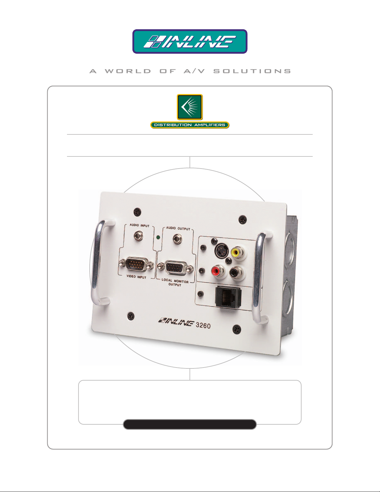
INSTALLATION DISTRIBUTION AMPLIFIER FOR HIGH RESOLUTION
VIDEO AND STEREO AUDIO WITH MODULAR A/V FACEPLATE
IN3260
IN3260
OPERATION MANUAL
High Resolution Video Products • A/V System Integration Tools • Interactive Training Systems
Page 2
Installation and Safety Instructions
For Models without a Power Switch:
The socket outlet shall be installed near the equipment and shall be accessible.
For all Models:
No serviceable parts inside the unit. Refer service to a qualified technician.
For Models with Internal or External Fuses:
For continued protection against fire hazard, replace only with same type and rating of fuse.
Instructions d’installation et de sécurité
Pour les modèles sans interrupteur de courant:
La prise de courant d’alimentation sera installé près de l’équipement et sera accessible.
Pour tout les modèles:
Pas de composants à entretenir à l’intérieur. Confiez toute réparation à un technicien qualifié.
Pour les modèles équipés de fusibles internes ou externes:
Afin d’éviter tout danger d’incendie, ne remplacer qu’avec le même type et la même valeur de fusible.
Installations- und Sicherheitshinweise
Für Geräte ohne Netzschalter:
Die Netzsteckdose soll in der Nähe des Gerätes installiert und frei zugänglich sein.
Für alle Geräte:
Keine Wartung innerhalb des Gerätes notwendig. Reparaturen nur durch einen Fachmann!
Für Geräte mit interner oder externer Sicherung:
Für dauernden Schutz gegen Feuergefahr darf die Sicherung nur gegen eine andere gleichen Typs und gleicher Nennleistung
ausgewechselt werden.
Instalacion E Instrucciones de Seguridad
Modelos Sin Interruptor:
Para Todos Los Modelos:
Modelos con Fusibles Internos o Externos:
La conexión debe ser instalada cerca del equipo y debe ser accesible.
Dentro de la unidad , no hay partes para reparar. Llame un tecnico calificado.
Para prevenir un incendio, reemplace solo con el mismo tipo de fusible.
CE COMPLIANCE
All products exported to Europe by Inline, Inc. after January 1, 1997 have been tested and found to
comply with EU Council Directive 89/336/EEC. These devices conform to the following
standards:
EN50081-1 (1991), EN55022 (1987)
EN50082-1 (1992 and 1994), EN60950-92
Shielded interconnect cables must be employed with this equipment to ensure compliance with
the pertinent Electromagnetic Interference (EMI) and Electromagnetic Compatibility (EMC)
standards governing this device.
FCC COMPLIANCE
This device has been tested and found to comply with the limits for a Class A digital device,
pursuant to Part 15 of the FCC rules. These limits are designed to provide against harmful
interference when equipment is operated in a commercial environment. This equipment generates,
uses and can radiate radio frequency energy and, if not installed and used in accordance with th e
instruction manual, may cause harmful interference to radio communications. Operation of
equipment in a residential area is likely to cause harmful interference, in which case the user will be
required to correct the interference at their own expense.
Page 3

Product Overview
DESCRIPTION
The IN3260 is a distribution amplifier for high-resolution computer video and stereo audio signals.
This unit is specifically designed to mount in a wall, conference table or podium in a standard 3-gang
junction box (included). The IN3260 accepts the high-resolution video signals from a computer
graphics card and the stereo audio signals from a computer sound card, then splits and amplifies the
signals so they can simultaneously drive two data grade displays and two audio devices. The most
common application for the IN3260 is to provide signals for a local monitor and a second display
device such as a data / presentation monitor or projector.
FEATURES
Easy Operation - The user simply brings in a computer and connects video and audio cables to the
nearest IN3260 distribution amplifier. This design eliminates the need to have a power supply,
distribution amplifier and thick output cable dangling from the computer, and promotes easy operation,
enhanced reliability, and a clean, high-tech look.
Modular Wall Plate - Available with a variety of popular connectors, the IN3260 faceplate can be
interfaced with up to three A/V modules. The unit can hold double size plates to accommodate large
connectors such as XLR. The IN3260 simplifies the design and installation process since a single unit
fills the function of both video / audio distribution amplifier and A/V wall plate.
15-Pin HD VGA Standard Connectors - The IN3260 connects directly to VGA graphics cards and
local monitors by using high-resolution coaxial VGA extension cables such as the IN8000 series. Input
/ output adapter cable sets are also available in a variety of lengths for MAC (15-Pin D), SUN (13W3),
SGI (13W3) and workstations (4 or 5 BNC).
Ultra High-Resolution Amplification - The IN3260 provides superb performance and maximum
image clarity at any resolution. Several design elements combine to provide this level of performance:
video bandwidth in excess of 400 MHz, a buffered local monitor output, and input / local monitor
output cables constructed of high-resolution coaxial materials.
Adjustable Video Output Gain - is a feature that boosts the output signal voltage to compensate for
signal loss occurring in long cable runs. Two separate sets of jumpers allow the installer to set unique
output gain levels as required for the Local Monitor Output (15-Pin HD on front) and the Main Output
(6-BNCs on back).
Sync Format / Polarity Preservation - The IN3260 output signals have the same sync format and
polarity as the input signal, ensuring excellent operation with a wide range of CRT, LCD, DMD, ILA
and plasma data display devices.
Stereo Audio Signal Balancing - The IN3260 provides stereo buffering and balancing to support
multimedia applications. The 3.5mm audio input jack accepts unbalanced stereo audio from the
computer sound card and splits / amplifies the signal. One output connector can feed a local audio
device such as powered speakers or an audio / video recorder, while the other can supply the line level
audio signal to a presentation monitor or house sound system. The local audio output is a 3.5mm stereo
mini jack that provides an unbalanced output signal. The main audio output (located on the back side
of the unit) is provided on a 5-pin creative screw terminal and can be set for either a balanced or
unbalanced output signal.
1
©2001 - INLINE, Inc. IN3260 Operation Manual - V 1.0 10/31/01
Page 4
2
Compatibility
INPUT
The IN3260 Installation Distribution Amplifier operates with analog video input from a wide
variety of IBM and compatible computer video signal formats including VGA, SVGA and XGA.
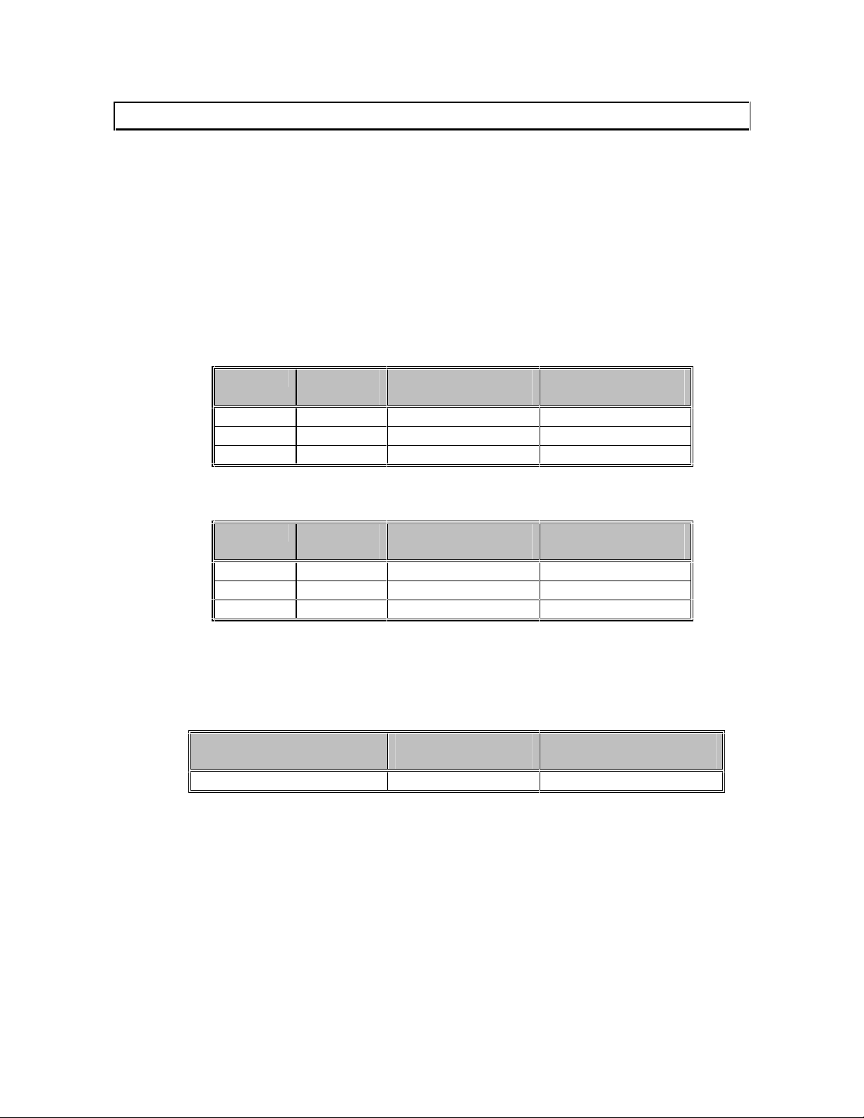
OUTPUT GAIN
To set the output gain for the main or local monitor outputs, close the appropriate jumpers
according to the table below. Be sure that the Red, Green and Blue output jumpers for each output
are all set to the same setting. The factory default setting for both outputs is unity gain.
Output Gain Jumper Settings for Output 1 (15-pin HD Local Monitor Output)
Red
Green
Blue
Output Gain Jumper Settings for Output 2 (6 BNC Main Output)
Red
Green
Blue
MONITOR EMULATION
Setting the jumpers according to the table below will configure the unit for automatic or manual
emulation:
Emulation for 15-pin HD
Male Input Connector
Pin 11 JP1 Open JP1 Closed
Automatic Factory Emulation (Factory Default)
When the unit is operating in automatic emulation mode, emulation sense pins are treated in the
following manner:
• Monitor Connected to Local Monitor Output - All sense pins are passed from the input
connector to the local monitor output connector, allowing the monitor to set the emulation
automatically.
• No Monitor Connection to the Local Monitor Output - The distribution amplifier
emulates a VGA Color / MAC 13” RGB monitor automatically.
Gain 1.0
(Unity)
9 8 7
13 12 11
16 15 14
Gain 1.0
(Unity)
19 18 17
22 21 20
25 24 23
Gain 1.2
(20% Signal Boost)
Gain 1.2
(20% Signal Boost)
Auto Emulation
(Factory Default)
Gain 1.4
(40% Signal Boost)
Gain 1.4
(40% Signal Boost)
Manual Emulation
(Pin Always Grounded)
IN3260 Operation Manual - V 1.0 10/31/01 ©2001 - INLINE, Inc.
Page 5
3
Manual Emulation Sense Pin Selection
The IN3260 cannot automatically emulate some MAC monitors. Some newer MAC G3 / G4
models require jumper pin 11 to be grounded in order for the PC to boot-up. Manually adjusting,
or grounding jumper pin 11, allows the user to force the video card into the proper configuration. If
so desired, grounding pin 11 on the video output connector [15-pin HD male] will achieve the same
results.
Note: JP2 must
be closed.
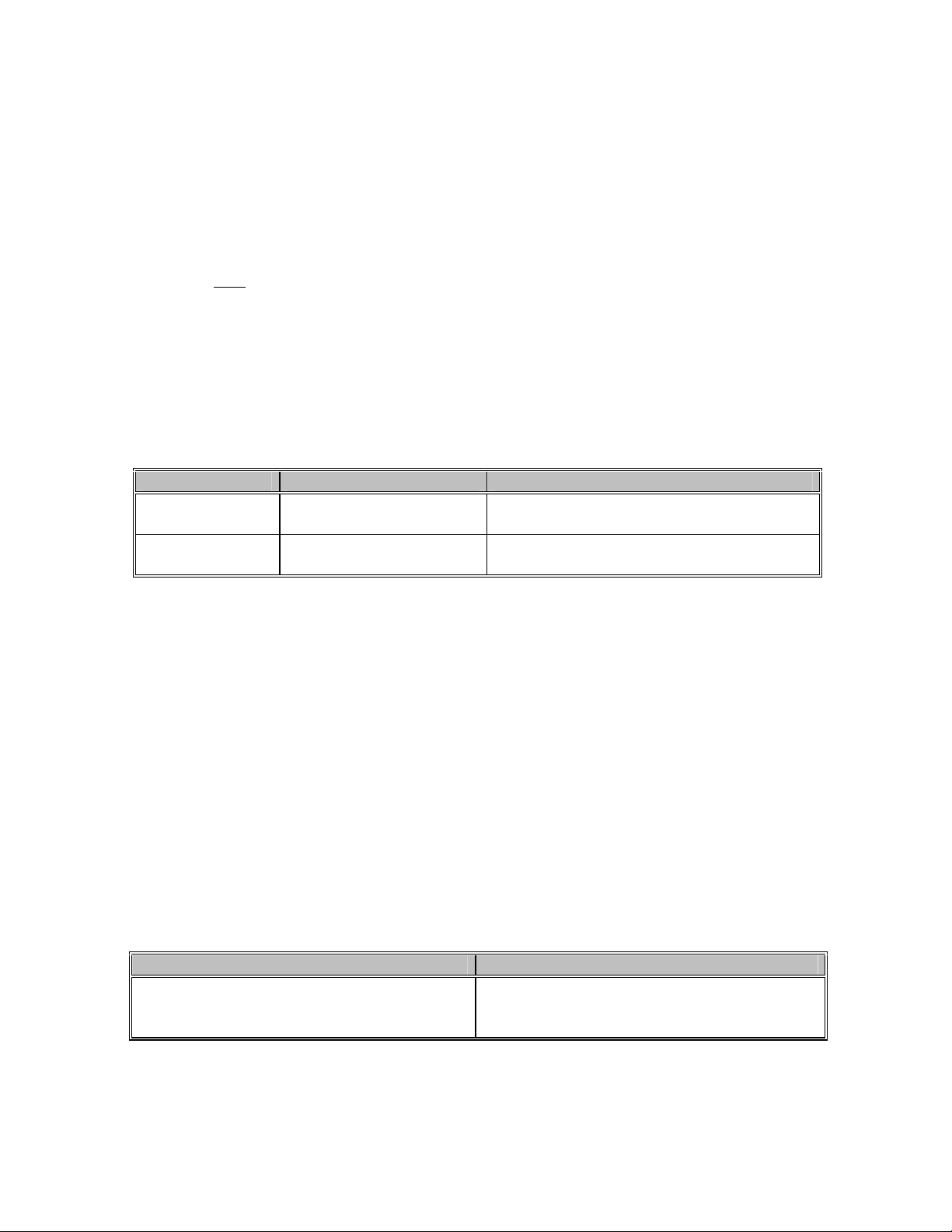
STEREO AUDIO BUFFER OPERATION
The IN3260 accepts unbalanced stereo audio signals applied to the 3.5mm stereo mini audio input
connector. This signal is amplified and split into the Local Audio and Main Audio Outputs as
indicated in the chart below:
Connector Type /
Location
Signal Format
Local Audio Output
The IN3260 outputs unbalanced stereo audio at the local audio connector, permitting a local audio
device such as powered speakers, an audio / video recorder or teleconferencing codec input to be
connected.
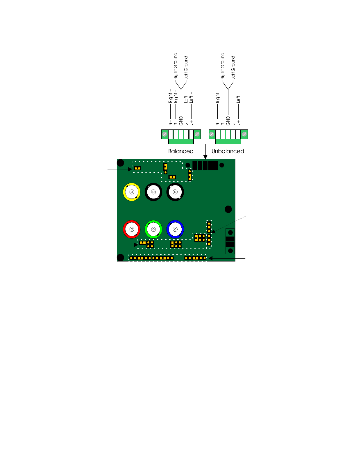
Main Audio Output
The main audio output is a 5-pin captive screw terminal located on the back of the video
distribution amplifier. The factory default signal for the main output is unbalanced audio. By
setting the jumpers (JP#) to the appropriate positions, the main output can be set for balanced
audio (see illustration on page 4). This is desirable for systems where the audio signal will be
connected to equipment with balanced audio inputs, and is helpful in preserving signal integrity
and minimizing outside signal interference when sending the audio signal over lengthy cable runs.
The main audio output can be set for balanced or unbalanced output by setting the four jumpers as
indicated below:
Unbalanced Output Signal (Factory Default) Balanced Output Signal
JP3 / JP4: Closed
JP5: Jumper Connects 2 Upper Pins
JP6: Jumper Connects 2 Lower Pins
Local Audio Output Main Audio Output
3.5mm Stereo Mini Female
Located on Interface
Unbalanced Audio
5-pin Captive Screw Terminal
Located on PCB
Balanced Audio (Factory Default) or Unbalanced Audio Depending on Jumper Settings
JP3 / JP4: Open
JP5: Jumper Connects 2 Lower Pins
JP6: Jumper Connects 2 Upper Pins
©2001 - INLINE, Inc. IN3260 Operation Manual - V 1.0 10/31/01
Page 6
4
Sett in gs fo r Outp ut 1 (HD15)
Blue J14/J15/J16
/
/
HIW
*
U
RXQ
G
/
HIW
IN3260 JUMPER ILLUSTRATION
G
Q
X
R
U
*
W
K
J
L
5
W
W
W
W
K
K
J
J
L
L
5
5
K
K
W
I
J
J
L
L
H
/
5
5
G
Q
G
X
Q
R
X
U
R
U
*
W
*
K
W
I
J
L
H
/
5
W
W
K
K
J
J
L
L
5
5
W
I
H
/
Unbalanced/Balanced
Audio Jumpers
J3/J4/J5/J6
Output Gain Jumpers
Settings for Output 2 (BNC)
Red J17 /J18/J19
Green J 20/ J21/J22
Blue J23/J24/J25
Horz
Sync
Vert
Sync
55*
5
'
1
/
5
55*
'
1
//
%DODQFHG 8QEDODQFHG
Comp
Sync
Monit or Emulation J ump er
for 15HD
J1
Output Gain Jumpers
Red J7/ J8/J9
Green J1/ J 12 /J1 3
IN3260 Operation Manual - V 1.0 10/31/01 ©2001 - INLINE, Inc.
Page 7

Installation
CAUTION: Installation of the IN3260 must only be carried out by qualified technicians. Care
must be taken to avoid static shock to the internal components.
This section offers step-by-step instructions for installing the IN3260. The front panel connector
diagram on page 8 shows the location and function of the IN3260 connectors. An application
diagram is included on page 7.
1. Install the junction box in accordance with standards set forth in the National Electrical
Code. Secure the junction box with nails (2 places minimum) if mounting to a wooden
stud or self-tapping screws when attaching to a metal stud. You may also install the
interface in an
existing 3-gang junction box. Run the video coax cable, power cable and stereo audio cables
(if used) to the junction box.
2. Connect the IN3260 output (6 BNC connectors) to the data display device’s RGB input, using
four, five or six high-resolution BNC cables or a multi-conductor RGBHV, RGBS, or RGsB
"snake" (most installations will require five or six connector cables). The IN7000 Series,
IN7200 Series, IN7300 Series and IN7400 Series high-resolution cables are well suited for
this purpose (see RGB INSTALLATION CABLE table on page 12). Take care while making
connections to ensure that the red output is connected to the red input, sync output to the sync
input, etc.
3. Connect the left, right and ground conductors on the audio cable to the IN3260 3-pin mini
Phoenix connector (J4). This connector will accept stranded or solid cables from 20 - 26
AWG.
4. Connect the power cable to the unit. The power connector has a sticker showing the correct
polarity. Be extra careful to connect positive to the (+) connector and negative to the (-)
connector. Connecting the power with reversed polarity may permanently damage the
unit! If in doubt, measure the power cable with a voltmeter to verify positive and
negative. The IN9204 9 VDC 500 mA power supply (included) will power one IN3260. You
may also use the optional IN9210 rack mounted power supply which will power up to 10
amplifiers. The power cable used to connect the power supply to the unit should be 18 gauge
to 22 gauge, depending on the length of the cable. INLINE offers the IN8500P-2 power cable,
an 18 gauge, 2-conductor, plenum rated cable.
5. The factory default setting is auto power disabled (P3 jumper placed on left pin and center pin)
meaning that the amplifier is powered up as long as 9VDC power is applied. If you want to
use the auto power (unit automatically powers up when the input cable is attached), move the
P3 jumper to cover the center pin and right pin (see illustration on previous page).
6. Carefully attach the IN3260 to the outlet box making sure that no cables are pinched or
damaged.
7. Turn the computer and computer monitor off. Disconnect the computer monitor (if present)
from the video output port on the computer.
5
©2001 - INLINE, Inc. IN3260 Operation Manual - V 1.0 10/31/01
Page 8

6
8. Connect the local computer monitor (if present) to the local monitor output of the IN3260.
VGA monitors will attach directly to the local monitor output. For other types of monitors,
use the appropriate local monitor output adapter cable (see list on page 13). No termination is
required if the IN3260 is use without a local monitor.
9. Connect the computer graphics card video output to the IN3260 Input using the appropriate
input cable (see list on page 13).
10. Connect the computer sound card output (if present) to the audio input connector using an
IN9106 audio patch cable. For computers with RCA connectors, use the IN9107 audio
adapter cable.
11. Complete the installation by turning the computer and computer monitor on.
IN3260 Operation Manual - V 1.0 10/31/01 ©2001 - INLINE, Inc.
Page 9

IN3260 APPLICATION DIAGRAM
7
Data Projector/
Pres entation Monitor
IN7000-5/IN7100-5/IN7200-5
IN8800 RGBHV Instalation Cable
Sound System
REAR VIEW
FRONT VIEW
IN9204P 9V 500MA
Power Supply
AUDIO INP U T
VIDEO INPUT
AUDIO OUTPUT
LOCAL M ONITOR
OUTPUT
3260
©2001 - INLINE, Inc. IN3260 Operation Manual - V 1.0 10/31/01
Page 10

8
IN3260 FRONT PANEL CONNECTOR DIAGRAM
Input Connector
S tereo Audio
Input
Power Indicator
S tereo Audio
Output
AUDIO INPUT
VIDE O INPUT
AUDIO OUTPUT
LOCAL M ONITOR
OUTPUT
3260
Local Monitor
Output (Buffered)
IN3260 Operation Manual - V 1.0 10/31/01 ©2001 - INLINE, Inc.
A/V Connector Modules
Page 11

A/V CONNECTOR MODULES
Connector Module
Black / White
Video Modules
IN9351B / IN9351W (2) BNC Female Barrel Single
IN9352B / IN9352W (1) 4-Pin Mini DIN Female (S-Video) Installation Single
IN9357B / IN9357W (2) F-Connector Female Barrel Single
IN9363B / IN9363W
IN9381B / IN9381W (1) BNC Female Barrel Single
IN9382B / IN9382W (1) F-Connector Female Barrel Single
IN9383B / IN9383W (1) RCA Female - White Barrel Single
IN9390B / IN9390W 4-Pin Mini DIN Female (S-Video) Barrel Single
IN9468B / IN9468W (2) 4-Pin Mini DIN Female Barrel (S-Video) Barrel Single
IN9475B / IN9475W (2) RCA Female to BNC Female Adapters Barrel Single
IN9476DB / IN9476DW (1) 4-Pin Mini DIN (S-Video) Quick Connect Double
Audio Modules
IN9353B / IN9353W (2) RCA Female - Red / White Installation Single
IN9354B / IN9354W (2) ¼” Stereo Phono Female Installation Single
IN9355B / IN9355W (2) 3.5mm Mini Stereo Female Installation Single
IN9360B / IN9360W
IN9365DB / IN9365DW (1) XLR 3-Pin Female (Neutrik) Installation Double
IN9373B / IN9373W (2) RCA Female - Red / White Barrel Single
IN9384B / IN9384W (1) ¼” Stereo Phono Female Installation Si ngle
IN9385B / IN9385W (1) 3.5mm Mini Stereo Female Installation Single
IN9395DB / IN9395DW (1) XLR 3-Pin Female (Switchcraft) Installation Double
IN9398DB / IN9398DW (1) XLR 3-Pin Male (Cannon) Installation Double
IN9450B / IN9450W (1) Mini XLR 3-Pin Male (Switchcraft) Installation Single
IN9451B / IN9451W (2) Mini XLR 3-Pin Male (Switchcraft) Installation Single
IN9456B / IN9456W (2) RCA Female - Red / White Quick Connect Single
IN9457B / IN9457W (2) 3.5mm Mini Stereo Female Quick Connect Single
IN9458B / IN9458W (1) 3.5mm Mini Stereo Female Quick Connect Single
IN9459B / IN9459W (1) ¼” Stereo Phono Female Quick Connect Single
IN9460B / IN9460W
IN9463B / IN9463W (1) Mini XLR 3-Pin Male (Switchcraft) Quick Connect Single
IN9473DB / IN9473DW (1) 4-Pole Speakon Male (Neutrik) Installation Double
Audio / Video Modules
IN9372DB / IN9372DW
IN9376DB / IN9376DW
IN9377DB / IN9377DW
IN9386B / IN9386W
IN9387B / IN9387W
IN9388B / IN9388W
IN9461DB / IN9461DW
IN9462DB / IN9462DW
IN9469B / IN9469W
(1) 4-Pin Mini DIN Female (S-Video)
(1) BNC Female Barrel
(1) Contact C losure Switch (Single Pole) with
Internal LED
(1) 3.5mm Stereo Mini Female
(1) Contact C losure Switch (Single Pole) with
External LED
(1) 3.5mm Mini Stereo Female
A/V Super Module:
(2) RCA Female - Audio: Red / White
(1) RCA Female - Video: Yellow
(1) 4-Pin Mini DIN Female - S-Video
A/V Super Module:
(2) RCA Female - Audio: Red / White
(1) RCA Female - Video: Yellow
(1) 4-Pin Mini DIN Female - S-Video
(2) RCA Female - Audio: Red / White
(1) RCA Female - Video: Yellow
(1) BNC Male
(2) 3.5mm Stereo Mini Female
(1) 4-Pin Mini DIN Female - S-Video
(1) 3.5mm Stereo Mini Female
(1) RCA Female - Video: Yellow
(1) 3.5mm Stereo Mini Female
A/V Super Module:
(2) RCA Female - Audio: Red / White
(1) RCA Female - Video: Yellow
(1) 4-Pin Mini DIN Female - S-Video
(2) RCA Female - Audio: Red / White
(1) RCA Female - Video: Yellow
(2) RCA Female - Audio: Red / White
(1) RCA Female - Video: Yellow
Description
Type
Barrel
Installation
Quick Connect
Installation
Barrel
Installation
BNC: Barrel
3.5mm Mini: Installation
Installation
Installation
Quick Connect
Quick Connect
Installation
Size
Single
Single
Single
Double
Double
Double
Single
Single
Single
Double
Double
Single
9
©2001 - INLINE, Inc. IN3260 Operation Manual - V 1.0 10/31/01
Page 12

10
Connector Module
Black / White
Description
Type
Size
Control / Computer Modules
CTL131DB / CTL131DW Remote IR Sensor Quick Connect Double
IN9356B / IN9356W (1) 5-Pin Captive Screw Terminal Installation Single
IN9360B / IN9360W
(1) Contact Closure Switch (Momentary - Single
Pole with LED)
Installation
Single
(1) 3.5mm Stereo Mini Female
IN9361B / IN9361W (1) 15-Pin HD Female Barrel Single
IN9362B / IN9362W (1) 15-Pin HD Male Barrel Single
IN9364DB / IN9364DW (1) XLR 4-Pin Female (Neutrik) Installation Double
IN9366DB / IN9366DW (1) XLR 6-Pin Female (Neutrik) Installation Double
IN9374B / IN9374W (1) 9-Pin D Female Barrel Single
IN9375B / IN9375W (2) 6-Pin Mini DIN Female - Keyboard / Mouse Barrel Single
IN9378B / IN9378W (1) 9-Pin D Male Barrel Single
IN9379B / IN9379W (1) 6-Pin Mini DIN Female - Keyboard / Mouse Installation Single
IN9389B / IN9389W (1) 6-Pin Mini DIN Female - Keyboard / Mouse Barrel Single
IN9391DB / IN9391DW (1) XLR 5-Pin Female (Neutrik) Installation Double
IN9394DB / IN9394DW (1) XLR 4-Pin Female (Switchcraft) Installation Double
IN9396DB / IN9396DW (1) XLR 6-Pin Female (Switchcraft) Installation Double
IN9397DB / IN9397DW (1) XLR 7-Pin Female (Switchcraft) Installation Double
IN9399B / IN9399W (1) Mini XLR 6-Pin Male (Switchcraft) Installation Single
IN9452B / IN9452W (1) Mini XLR 4-Pin Male (Switchcraft) Installation Single
IN9460B / IN9460W
(1) Contact C losure Switch (Momentary - Single Pole
with LED)
Quick Connect
Single
(1) 3.5mm Stereo Mini Female
IN9464B / IN9464W (1) Mini XLR 4-Pin Male (Switchcraft) Quick Connect Single
IN9465B / IN9465W
(1) Rocker Switch (Latching - Single Pole),
Max Voltage: 10A / 125VAC, 6A / 250VAC
Installation
Single
Approvals: UL / CSA
IN9466B / IN9466W (2) 6-Pin Mini DIN Female - Keyboard / Mouse Installation Single
IN9467B / IN9467W (1) USB Connector Quick Connect Single
IN9470B / IN9470W
(1) Switch with Integral LED:
(Latching, Single Pole, Sin gle Throw)
Max. Voltage: 5A / 125VAC, 3A / 250VAC
Installation
Single
Approvals: CSA
IN9471B / IN9471W
(1) Switch: (Latching, Single Pole, Double Throw)
Max. Voltage: 15A / 125VAC,
10A / 250VAC, 10A / 28VDC
Installation
Single
Approvals: CSA
IN9472DB / IN9472DW
(1) Switch: (Latching, Double Pole, Double
Throw) Max. Voltage: 15A / 125VAC,
10A / 250VAC, 10A / 28VDC
Installation
Double
Approvals: CSA
Data / Phone Modules
IN9358B / IN9358W (1) RJ11 Female - Phone Installation Single
IN9358DB / IN9358DW (1) RJ11 Female - Phone Installation Double
IN9359B / IN9359W (1) RJ45 Female - Data Installation Single
IN9359DB / IN9359DW (1) RJ45 Female - Data Installation Double
IN9453B / IN9453W (1) RJ11 Female - Phone Barrel Single
IN9453DB / IN9453DW (1) RJ11 Female - Phone Barrel Double
IN9454B / IN9454W (1) RJ45 Female - Data Barrel Single
IN9454DB / IN9454DW (1) RJ45 Female - Data Barrel Double
Blank Plate
IN9350B / IN9350W Blank Plate - Single Single
IN9367DB / IN9367DW Blank Plate - Double Double
IN9368TB / IN9368TW Blank Plate - Triple Triple
IN9369QB / IN9369QW Blank Plate - Quad Quad
IN9474QB / IN9474QW (1) Grommet - 1” ID Quad
INLINE A/V Connector Modules are designed to work with: CIA 100 Series / IN2111 Series / IN2112 Series / IN2114
/ IN2116 / IN2118 Interfaces; DAV151 VGA & Stereo Audio Line Drivers; TPT111 Twisted Pair Transmitters;
IN3260 Video Distribution Amplifiers; IN9254 Rack Mount Ears for the CIA116 Interface; IN9166 / IN9167 / IN9168
Modular A/V Connector Plates; IN9172 Rack Mountable Modular A/V Connector Plates; IN9177 Table Mountable
Modular Connector Bays; CPM115 / IN9179 / IN9180 Modular A/V Connector Plates (for Steel City® floor boxes)
IN3260 Operation Manual - V 1.0 10/31/01 ©2001 - INLINE, Inc.
Page 13

Specifications
IN3260
Installation Distribution Amplifier
Input
Connector Type (1) 15-pin HD male (female connector available upon request)
RGB Video Signal Analog, 1.5 Vp-p max.
Input Terminations 75 ohms
Sync Signals TTL compatible
Compatible Formats RGBHV / RGBS / RGsB / RGBHVS
Horizontal Sync Range 15 to 130 KHz
Vertical Sync Range 30 to 120 Hz
Stereo Audio Input 3.5mm Stereo Mini Female, Unbalanced Audio
Output
Buffered Local Monitor 15-pin HD female (male connector available upon request)
Main Output Six (6) BNC female
Output Format Same as Input - RGBHV / RGBS / RGsB / RGBHVS
Video Gain 1.0 / 1.2 / 1.4
Local Audio Output 3.5mm Stereo Mini Female, Unbalanced Audio
Main Audio Output 5-Pin Captive Screw Terminal, Unbalanced (Default) or Balanced
General
Bandwidth 400 MHz @ -3 dB
Internal Jumpers
Power
Power Supply 9 VDC, 500 mA
Dimensions
Size (including J-Box) 4.5” x 6.4” x 2.6” / 11.4cm x 16.3cm x 6.6cm
Weight Shipping: 4lbs. / 2 kg. Product: 2lbs. / 0.9 kg.
Regulatory Compliance
Safety UL 1950, CAN/CSA-22.2 No. 950, Third Edition
EMI
Parts Included
(1) IN3260 Installation Distribution Amplifier
(1) IN9204 External Power Supply
(1) IN9334 Allen Wrench
(1) IN9161 3-Gang Junction Box - 2.5” Deep
(1) IN9154 ¾” EMT Conduit Coupler, Set-Screw Type
Local Monitor Output Gain, Main Output Gain,
Audio Output Balanced / Unbalanced,
Monitor Emulation Auto / Always Grounded
FCC class A; CE: EN55022 (1987), EN50081-1 (1991),
EN50082-1 (1992 and 1994), EN60950-92
11
©2001 - INLINE, Inc. IN3260 Operation Manual - V 1.0 10/31/01
Page 14

12
Required Accessories (Ordered Separately)
Input and Local Monitor Adapter and Extension Cables:
VGA: IN8000 Series 15-pin HD male to 15-pin HD female, various lengths from 3’ to 100’
For Other Monitors: see the list on the following page
Optional Accessories
Power Equipment:
IN9210: Rack mountable power supply, powers up to ten 9 VDC / 12 VDC devices
IN8500 Power Cable: 18 Gauge, 2-Conductor power cable, bulk.
Note: When extending power distances of 50 feet or more, use 18 gauge (or thicker) power
cable. Thinner cables may cause problems.
Audio Input / Output Adapter and Extension Cables:
IN9106: 3.5mm stereo mini male to 3.5mm stereo mini male, 6’ long
IN9107: (1) 3.5mm stereo mini male to (2) RCA male, 6’ long
Installation Cables:
IN7000P-5 Series RGBHV Cable: Standard Resolution, Plenum Cable available in bulk lengths
IN7000P-5K Series RGBHV Cable: Standard Resolution, Plenum Cable available in 1000’ bulk
length
IN8800: 18 Conductor Super High-Resolution Cable: (3) Super High-Res. Coax., (3) Mini
Coax., (5) 26 Gauge Twisted Pairs, (1) Gauge Pair
Installation Accessories:
IN9162: 3-Gang Junction Box, 3.5” Deep - For Use With IN7200 Series Cables
IN9155: ¾” Romex Connector, Cable Strain Relief
Coaxial Cables 1-Conductor 3-Conductor 5-Conductor
Standard Resolution
Standard Resolution, Plenum
Super High Resolution
Super High Resolution, Plenum
Ultra High Resolution
All cable grades are available in lengths from 3’ to 250’ pre-terminated with high quality BNC connectors or as bulk cable.
IN7000-5
IN7000P-5
IN7300-3 IN7300-5
IN7400P-5
IN7200-1 IN7200-3 IN7200-6
IN3260 Operation Manual - V 1.0 10/31/01 ©2001 - INLINE, Inc.
Page 15

13
ADAPTER / EXTENSION CABLES FOR INPUT AND LOCAL MONITOR OUTPUT
The IN3260 has 15-pin HD VGA-type input and local monitor output connector ports. The
following cables / adapters are available:
Computer 3’ 6’ 12’ 25’
VGA: 15-Pin HD
Input Cable
Output Cable (Optional
MAC with 15-Pin D:
Input Cable
Output Cable
MAC G3, G4 and PowerBook with 15-Pin HD*:
Input Cable
Output Cable
IN8006 IN8012 IN8025
IN8006 IN8012 IN8025
SUN: 13W3 (may also be used with SGI with RGsB output)
Input Cable
Output Cable
Workstation: 5 BNC / RGBHV
Input Cable
Output Cable
IN9046-L6 IN9046-L12 IN9046-L25
IN9045-L6 IN9045-L12 IN9045-L25
Workstation: 4 BNC / RGBS
Input Cable
IN9100
*Newer Mac G3 models (with translucent cases) have 15-Pin HD connectors (pins arranged in 3 rows).
Older G3 models (with solid white enclosures) incorporate 15-Pin D connectors (pins arranged in 2 rows).
IN8006 IN8012 IN8025
IN8006 IN8012 IN8025
IN9140 IN9144
IN9141 IN9145
IN9142 IN9146
IN9143 IN9147
©2001 - INLINE, Inc. IN3260 Operation Manual - V 1.0 10/31/01
Page 16

14
Troubleshooting
Problem: The display device connected to the IN3260 output has a bad/scrambled
image.
Solution 1: Verify that the correct input cable is being used (see the table on the previous
page).
Solution 2: The display device connected to the output of the interface may not be compatible
with the computer output. Standard 640 x 480 VGA runs at 31.5 KHz, but SVGA
can be as high as 48 - 58 KHz depending on the vertical refresh rate. PC, MAC,
Sun and other high resolution workstations have new ultra high resolution modes
such as 1600 x 1200 and 1800 x 1440 and can output a video signal with a
horizontal scan rate of over 100 KHz! Many data monitors and data projectors are
not compatible with these resolutions and frequencies.
Solution 3: The RGBS or RGBHV cable may have a bad sync line. Try running the sync
through another cable (i.e. temporarily use the red coax to connect the sync).
Problem: The local monitor looks fine but the image on the LCD projector is wavy or
has vertical bars in the picture.
Solution 1: LCD / DMD displays often have an adjustment called Phase Adjust or Fine Phase
Control. This control should be adjusted to provide the best image.
Problem: The output image is doubled, with two images displayed side-by-side.
Solution: The display device may not be compatible with the horizontal scan rate of the
computer. This problem often occurs when a 31.5 KHz VGA signal is sent into an
RGB monitor that is only compatible with signals at 15.75 KHz.
If problems persist, call INLINE Technical Services at (714) 450-1800 for further assistance.
You may also send email to tech@inlineinc.com. or send a fax to (714)450-1850.
IN3260 Operation Manual - V 1.0 10/31/01 ©2001 - INLINE, Inc.
Page 17

15
Warranty
• INLINE warrants the equipment it manufactures to be free from defects in materials and
workmanship.
• If equipment fails because of such defects and INLINE is notified within three (3) years from
the date of shipment, INLINE will, at its option, repair or replace the equipment at its plant,
provided that the equipment has not been subjected to mechanical, electrical, or other abuse or
modifications.
• Equipment that fails under conditions other than those covered will be repaired at the current
price of parts and labor in effect at the time of repair. Such repairs are warranted for ninety
(90) days from the day of re-shipment to the Buyer.
• This warranty is in lieu of all other warranties expressed or implied, including without
limitation, any implied warranty or merchantability or fitness for any particular
purpose, all of which are expressly disclaimed.
The information in this manual has been carefull y checked and is believed to be accurate. Ho wever,
INLINE, Inc. assumes no responsibility for any inaccuracies that may be contained i n this manual. In no
event will INLINE, Inc. be liable for direct, indirect, special, incidental, or consequential damages
resulting from any defect or omission in this manual, even if advised of the possibility of such damages.
The technical information contained herein regarding IN3260 features and specifications is subject to
change without notice.
IBM is a registered t rademark of International Business M achines. Sun and SP ARC are trademarks of
Sun Microsystems. SGI is a trademark of Silicon Graphics, Inc. All other trademarks and registered
trademarks are the property of their respecti ve co mpanies.
© Copyright 2001 INLINE, Inc. All Rights Reserved
INLINE, INC. ♦ 810 WEST TAFT ♦ ORANGE, CA 92865
©
(800) 882-7117 ♦ (714) 450-1800 ♦ FAX (714) 450-1850 ♦ www.inlineinc.com
©2001 - INLINE, Inc. IN3260 Operation Manual - V 1.0 10/31/01
 Loading...