

Page 1
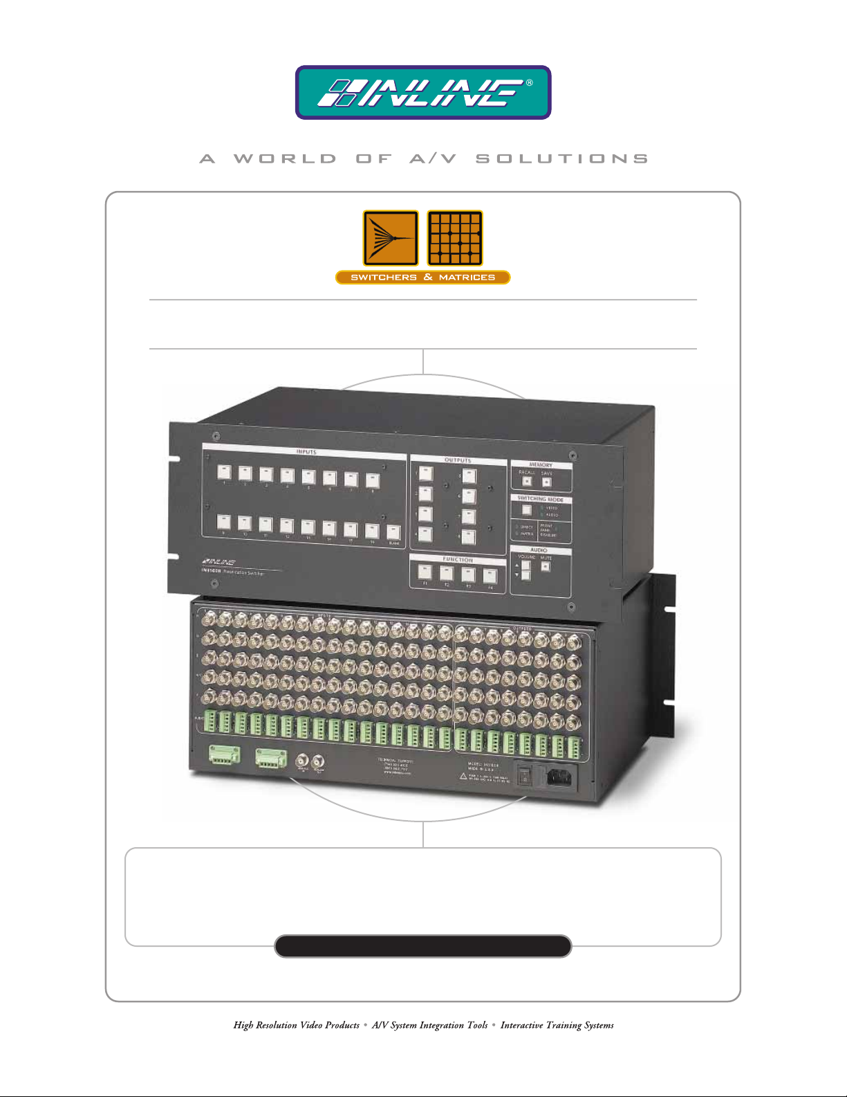
IN31608 PRESENTATION SWITCHER
16–INPUT, 8–OUTPUT
IN31608
OPERATION MANUAL
Page 2
Installation and Safety Instructions
For Models without a Power Switch:
The socket outlet shall be installed near the equipment and shall be accessible.
For all Models:
No serviceable parts inside the unit. Refer service to a qualified technician.
For Models with Internal or External Fuses:
For continued protection against fire hazard, replace only with same type and rating of fuse.
Instructions d’installation et de sécurité
Pour les modèles sans interrupteur de courant:
La prise de courant d’alimentation sera installé près de l’équipement et sera accessible.
Pour tout les modèles:
Pas de composants à entretenir à l’intérieur. Confiez toute réparation à un technicien qualifié.
Pour les modèles équipés de fusibles internes ou externes:
Afin d’éviter tout danger d’incendie, ne remplacer qu’avec le même type et la même valeur de fusible.
Installations- und Sicherheitshinweise
Für Geräte ohne Netzschalter:
Die Netzsteckdose soll in der Nähe des Gerätes installiert und frei zugänglich sein.
Für alle Geräte:
Keine Wartung innerhalb des Gerätes notwendig. Reparaturen nur durch einen Fachmann!
Für Geräte mit interner oder externer Sicherung:
Für dauernden Schutz gegen Feuergefahr darf die Sicherung nur gegen eine andere gleichen Typs und gleicher Nennleistung
ausgewechselt werden.
Instalacion E Instrucciones de Seguridad
Modelos Sin Interruptor:
Para Todos Los Modelos:
Modelos con Fusibles Internos o Externos:
La conexión debe ser instalada cerca del equipo y debe ser accesible.
Dentro de la unidad , no hay partes para reparar. Llame un tecnico calificado.
Para prevenir un incendio, reemplace solo con el mismo tipo de fusible.
CE COMPLIANCE
All products exported to Europe by Inline, Inc. after January 1, 1997 have been tested and found to
comply with EU Council Directive 89/336/EEC. These devices conform to the following
standards:
EN50081-1 (1991), EN55022 (1987)
EN50082-1 (1992 and 1994), EN60950-92
Shielded interconnect cables must be employed with this equipment to ensure compliance with
the pertinent Electromagnetic Interference (EMI) and Electromagnetic Compatibility (EMC)
standards governing this device.
FCC COMPLIANCE
This device has been tested and found to comply with the limits for a Class A digital device,
pursuant to Part 15 of the FCC rules. These limits are designed to provide against harmful
interference when equipment is operated in a commercial environment. This equipment generates,
uses and can radiate radio frequency energy and, if not installed and used in accordance with th e
instruction manual, may cause harmful interference to radio communications. Operation of
equipment in a residential area is likely to cause harmful interference, in which case the user will be
required to correct the interference at their own expense.
Page 3

Table of Contents
Product Overvie w.....................................................................................................................1
Description ...............................................................................................................................1
Front Panel Controls ...............................................................................................................1
Switching - Connecting Inputs and Outputs (Front Panel)............................................2
Direct Mode..............................................................................................................................2
Matrix Mode.............................................................................................................................2
Group Configuration.................................................................................................................2
Switching Event Order .............................................................................................................3
Genlock Operation / Vertical Interval Switching.............................................................3
RGB Delay..................................................................................................................................3
Audio............................................................................................................................................4
Volume Up/Down.....................................................................................................................4
Mute..........................................................................................................................................4
Volume Up / Down & Mute for [SW] Command....................................................................4
Input Volume............................................................................................................................5
Unbalanced Audio Settings ......................................................................................................5
Balanced Audio Settings...........................................................................................................6
Audio Input / Output Connections............................................................................................6
Direct Mode Setup (Front Panel)..........................................................................................7
Saving and Recalling Setup Memories for the Matrix Mode.........................................7
Power-On Settings....................................................................................................................8
IN31608 Power On Options.....................................................................................................8
Reset to Factory Default (F1), (BLANK).................................................................................8
Front Panel Test Mode..............................................................................................................9
Matrix / Direct Mode Selection................................................................................................9
Direct Mode Setup....................................................................................................................9
Projector Memory Test Mode...................................................................................................9
Clear Projector Memories.........................................................................................................9
Genlock operation / vertical interval switching........................................................................9
RGB Delay ...............................................................................................................................9
Projector Control Port..........................................................................................................10
Serial Control Port.................................................................................................................10
Protocol...................................................................................................................................10
Structure .................................................................................................................................10
Command Code Definitions ...................................................................................................11
Serial Port Pin Definitions......................................................................................................11
Serial Control Command Description...............................................................................11
[STAT] Command Examples.................................................................................................18
Specifications...........................................................................................................................20
Troubleshooting...................................................................................................................... 21
Warranty..................................................................................................................................22
Page 4

1
Product Overview
DESCRIPTION:
The IN31608 Presentation Switcher combines the easy operation and serial control capabilities of a projector
switcher with the flexibility of a matrix switcher. Featuring RGBHV + stereo audio matrix switching, 350 MHz
bandwidth and two switching modes, the IN31608 is ideal for permanent installations, rentals, complex staging
operations and any other display system requiring a high performance, economical presentation switcher.
Direct Switching Mode - In the Direct Mode, the IN31608 acts as a projector switcher, routing composite, S-
Video and RGB signals to the appropriate outputs. The user simply presses one of the input buttons and that
input signal is automatically routed to the pre-programmed output(s).
Matrix Switching Mode - For advanced applications requiring multiple outputs, the IN31608 can operate as a
true 16 x 8 matrix switcher. In the Matrix Mode, users press an output button followed by an input button and a
new patch is immediately executed.
Projector Control - The IN31608 can store and transmit serial ASCII or hex projector control strings to
projectors, INLINE products or other serial controlled AV equipment in RS-232, RS-422 or RS-485 modes.
Windows
projector control strings are provided by the installing technician.
TM
software provided with the switcher makes it easy to set up the unit and store control codes. All
Front Panel Controls
INPUT 1 - 16:.............. Selects a particular input
BLANK: ...................... Selects no input (Blanks the selected output)
OUTPUT 1 - 8:............ Selects a particular output for the Matrix Mode and Direct Mode Setup
SAVE, RECALL: ....... For Matrix Mode only, saves or recalls a memory configuration
MUTE:......................... Mutes the audio for the selected output
VOLUME ¾:.............. Increases the volume
VOLUME ¿:.............. Decreases the volume
F1, F2, F3 and F4: ...... Sends the pre-programmed code out the projector port
SWITCHING MODE:For Matrix Mode (only), selects the current switching mode as either:
1) Video, Sync, and Audio
2) Video and Sync only
3) Audio only
2001 - INLINE, Inc. IN31608 OPERATION MANUAL - REV 1.6 1/4/01
Page 5

2
Switching - Connecting Inputs and Outputs (Front Panel)
DIRECT MODE
Press the button of the input you desire and the signal will automatically be sent to the appropriate output(s).
Video, sync and audio are always routed together as a group (see DIRECT MODE SETUP on page 7 for more
details.) That input LED will light as well as any of the selected output LEDs. To disconnect all outputs press
the Blank Button.
MATRIX MODE
To make a new connection between an input and an output, the order of button presses is always output then
input as described below.
First press the button of the output you would like to change. The selected output LED will light (only one
output can be selected at a time). The LED of the input currently patched to that output will also light. To
select a different input, press the button of the input you desire. To blank the output, press the Blank Button.
Once an output is selected, the inputs may be changed indefinitely.
GROUP CONFIGURATION (MATRIX MODE ONLY)
In Matrix Mode, it is possible to switch video, sync and audio together or separately using the front panel
Switching Mode Button or the serial commands.
Board Group Selection from the Front Panel - Switching multiple board groups is possible through the front
panel. To select the switching mode depress the Mode Button. The switching mode sequences between three
possible combinations in the following order:
1) VIDEO / AUDIO / SYNC (default) - video and audio LEDs on
2) VIDEO / SYNC ONLY - only video LED on
3) AUDIO ONLY - only audio LED on
Board Group Selection Using Serial Commands - It is also possible to switch audio, video, and sync
together, separately or in almost any combination using the serial [CNF…] command. The [CNF…] command
defines three groups. Each group is treated as an independent switcher within the unit, and can be switched
independently. The factory default is to have all boards assigned to Group 1 so that they switch together.
One of the most common uses of assigning multiple groups is to switch audio independent of video. Assigning
the RGB and sync boards to Group 1, and the audio to Group 2 will accomplish this. Doing so allows Group 1
and Group 2 can be switched independently.
The IN31608 allows breakaway audio, video and sync in any combination through serial commands. However,
there are only video and audio LEDs on the front panel to make this distinction. When sync is switched
separately from video and audio, the unit automatically disables the front panel input and output switches and
flashes the video and audio LEDs. The switcher is designed this way to protect the user from setting a
breakaway sync mode with a serial command and subsequently switching the front panel manually without
realizing that sync is being switched separately from audio and video.
IN31608 OPERATION MANUAL - REV 1.6 1/4/01 2001 - INLINE, Inc.
Page 6

3
SWITCHING EVENT ORDER
The following procedure describes the precise order of events each time a switch is made.
1) Wait for:
a) Next sync signal (genlock operation / vertical interval switching only), or
b) Timer time-out, whichever comes first.
2) If video included in switch group (video always included in switch group for Direct Mode):
a) Update video array for particular in-to-out channel.
b) Set video switch to array but don’t update yet.
3) If sync included in switch group (sync always included in switch group for Direct Mode):
a) Determine which input is currently connected to the output in question.
b) Disconnect and update sync array (if sync channel is currently connected).
c) Connect new sync channel and update sync array.
4) RGB delay - Variable delay time according to value set for RGB Delay.
5) If video included in switch group (video always included in switch group for Direct Mode):
a) Update video switch.
6) Send projector codes:
a) If output changed, send projector output code and wait for projector code delay.
b) Send projector input code.
7) If audio included in switch group (audio is always included in switch group for Direct Mode):
a) Determine which input is currently connected to the output in question.
b) Disconnect and update audio array (if audio channel is currently connected).
c) Update audio volume for particular in-to-out channel.
d) Connect new audio channel and update audio array.
Genlock Operation / Vertical Interval Switching
The IN31608 can provide genlock operation / vertical interval switching when used with synchronous video
sources. The unit has two BNC connectors on the rear panel to allow loop through of a house sync or black
burst signal.* If this sync signal is active, the IN31608 will delay the switch so that it begins with the leading
edge of vertical sync. Genlock operation / vertical interval switching is disabled while in factory default mode,
and may be enabled by pressing Output 4 during power up (see page 9). Alternatively, the [VIS0] and [VIS1]
serial commands disable and enable the genlock operation / vertical interval switching, respectively. Refer to
the Switching Event Order section above for the precise order of events each time a switch is made.
*Note: When using the loop through feature, the unused BNC connector requires a 75 Ohm termination plug (IN9130).
RGB Delay
RGB Delay is a key feature of the IN31608. It provides an adjustable delay time between switching the sync
and RGB boards. The delay time can be set from 0 to 6 seconds (in 500 millisecond intervals) by front panel
power up settings or serial commands.
When RGB delay is engaged, the sync signals are connected first and the video and audio signals are blanked
for the delay time to allow the display device to lock up to the new signal. After the delay time, the video and
audio signals are connected. When set to the factory default of 0 seconds, video, sync, and audio switch at the
same time. The RGB delay can be set via a Power On setting or via serial commands (see those sections for
more detail).
2001 - INLINE, Inc. IN31608 OPERATION MANUAL - REV 1.6 1/4/01
Page 7

4
sizing and other spurious
RGB delay prevents the display device from showing reon-screen effects that often occur while the display is adjusting to the new signal.
Audio
In Matrix Mode, the audio for the selected input is routed to the selected output. Note that the video, audio, and
sync may be switched independently in Matrix Mode. In Direct Mode the audio of the selected input is sent to
the selected output(s). The front panel volume control and the serial volume commands are mutually
exclusively enabled. On power up, the front panel volume controls are enabled and the serial volume
commands are disabled. The serial command [MDVOL0] enables the front panel volume controls and disables
the serial volume commands. The serial command [MDVOL1] disables the front panel volume controls and
enables the serial volume commands.
The IN31608 has Volume Up and Down Buttons as well as a Mute Button. These buttons function as follows:
VOLUME UP / DOWN
The Volume Up Button increases the output volume and the Volume Down Button decreases it.
Matrix Mode - When the Volume Up / Down Button is depressed the volume of the currently selected output
volume is incremented / decremented. If the button is held for one second, a fast increment / decrement mode
is entered and the Output Button’s LED flashes until the maximum / minimum output volume is reached.
Direct Mode - The volume control for Direct Mode works similarly to the volume control for Matrix Mode
except that the output volume is controlled simultaneously for all outputs.
The output volume information is retained in non-volatile memory and can only be modified by the procedure
described below or the serial volume commands [VOL…]. In Matrix Mode, output volume information is
retained separately in non-volatile memory for all 16 channels. In Direct Mode, a global output volume control
is retained in non-volatile memory that controls all outputs.
MUTE
The Mute Button disengages the audio signal. When the audio is muted (no audio) the mute LED turns on. The
audio will remain muted until it is reactivated by pressing the button again. In the Matrix Mode, the audio of
the currently selected output is muted. In the Direct Mode, all outputs are muted simultaneously. Muting does
not affect the previously selected input or output volumes. The mute information is retained in non-volatile
memory and can only be modified by the procedure described above or the serial command [MUTE…]. In
Matrix Mode, mute information is retained separately for all 16 channels. In Direct Mode, a global mute
controls all outputs.
VOLUME UP / DOWN AND MUTE FOR [SW] COMMAND
An alternative way of adjusting the volume and mute settings (associated with the [SW] command) with
a serial command (such as [LVOL…]) is to make the adjustments as described above, then press the
SAVE key followed by the BLANK key. The current volume and mute settings will override the
settings previously stored and will be used with subsequent [SW] commands.
IN31608 OPERATION MANUAL - REV 1.6 1/4/01 2001 - INLINE, Inc.
Page 8
5
INPUT VOLUME
If the Mute Button is depressed simultaneously with the Volume Up / Down Button, the input volume for the
currently selected input is affected instead of the output volume. In this case the Input Button’s LED flashes
until the maximum / minimum input volume is reached. By adjusting input levels, the levels of all the various
input sources can be equalized. This is important so the volume level does not increase / decrease dramatically
when switching between inputs. The input volume information is retained in non-volatile memory and can only
be modified by the procedure described on the previous page.
The actual volume adjustment is calculated by adding the input volume setting and output volume setting
together, and truncating the total at a maximum setting of 255. The total volume is mapped to a linear scale
from -96.0 dB to +31.5 dB in increments of 0.5 dB. A total volume of 0 corresponds to -96.0 dB and a total
volume of 255 corresponds to +31.5 dB. The default input value is mid scale (128) to allow for maximum input
volume adjustment in both directions. The default output value for both left and right channels is 52, so that the
default sum of input and output volumes for both left and right channels is -3 dB.
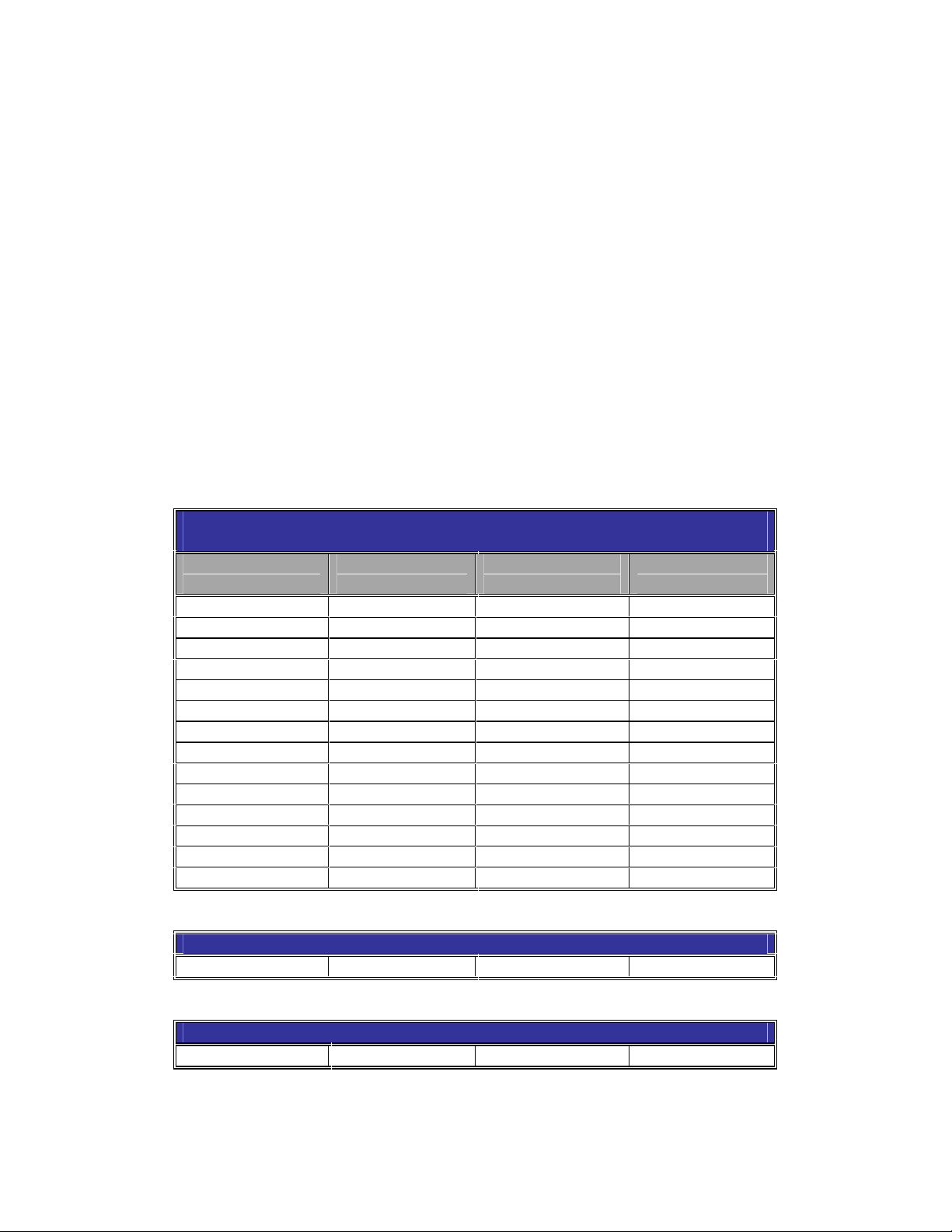
UNBALANCED AUDIO SETTINGS
INPUT AUDIO LEVEL STIMULUS = -10 dBm
INPUT AUDIO LEVEL SET AT 128 DECIBALS
OUTPUT LEVEL
VALUE YYY
120 18.0 55 -14.5
115 15.5 50 -17.0
110 13.0 45 -19.5
105 10.5 40 -22.0
100 8.0 35 -24.0
95 5.5 30 -27.0
90 3.0 25 -29.5
85 0.5 20 -32.5
84 0.0 15 -34.5
80 -2.0 10 -37.0
75 -4.5 5 -9.5
70 -7.0 0 -42.0
65 -9.5
60 -12.0
INPUT AUDIO LEVEL STIMULUS = 8.5 dBm
84 18.4
INPUT AUDIO LEVEL STIMULUS = 0.0 dBm
84 9.94
Note: Input and Output audio levels are summed internally to give the total audio level
GAIN
(dBm)
OUTPUT LEVEL
VALUE YYY
GAIN
(dBm)
2001 - INLINE, Inc. IN31608 OPERATION MANUAL - REV 1.6 1/4/01
Page 9

6
5LJKW
5LJKW
5LJKW
5LJKW
/HIW
BALANCED AUDIO SETTINGS
INPUT AUDIO LEVEL STIMULUS = -10 dBm
INPUT AUDIO LEVEL SET AT 128 DECIMAL
OUTPUT LEVEL
VALUE YYY
117 17.6 52 -14.9
112 15.1 47 -17.3
102 10.1 42 -19.9
97 7.64 37 -22.35
100 5.13 32 -24.0
92 5.5 30 -27.9
87 2.65 27 -29.5
85 0.5 20 -27.4
82 0.0 22 -32.4
77 -2.4 17 -34.9
72 -4.9 12 -37.4
67 -7.4 7 -39.8
62 -9.9 2 -42.9
57 -12.4 0
INPUT AUDIO LEVEL STIMULUS = 8.5 dBm
82 18.6
INPUT AUDIO LEVEL STIMULUS = 0.0 dBm
99 18.6
82 10.15
Note: Input and Output audio levels are summed internally to give the total audio level
GAIN
(dBm)
OUTPUT LEVEL
VALUE YYY
GAIN
(dBm)
AUDIO INPUT / OUTPUT CONNECTIONS
)RU8QEDODQFHG6WHUHR$XGLR,QSXW
5LJKW
5LJKW*URXQG
/HIW*URXQG
/HIW
)RU8QEDODQFHG6WHUHR$XGLR2XWSXW
5LJKW
5LJKW*URXQG
/HIW*URXQG
/HIW
IN31608 OPERATION MANUAL - REV 1.6 1/4/01 2001 - INLINE, Inc.
)RU%DODQFHG6WHUHR$XGLR,QSXW
5LJKW*URXQG
/HIW*URXQG
/HIW
/HIW
)RU%DODQFHG6WHUHR$XGLR2XWSXW
5LJKW*URXQG
/HIW
/HIW*URXQG
Page 10

7
Direct Mode Setup (Front Panel)
In the Direct Mode, inputs are assigned to a designated output and automatically routed to the output(s) when
selected. This section describes the procedure to assign inputs to outputs via the front panel.
1. Enter the Direct Mode Setup with the appropriate power on setting (see Power On Settings section on
page 8 for more details.) Once in the Direct Mode Setup, all output LEDs and the direct LED will
flash. To exit the setup with no changes, press the Save Button.
2. Press the Output Button of the output you would like to assign inputs to. The selected output LED will
turn on while the other 7 output LEDs and the direct LED will continue to flash. The input LED(s)
currently associated with the selected output LED will turn on.
3. Press the Input Button(s) of the input(s) you would like to assign to that output. The input LED(s) will
turn on. To disengage a selected input simply press that Input Button again.
4.
Repeat steps 2 and 3 for all outputs.
5. Press the Save Button to save your changes and exit the Direct Mode Setup.
The Direct Mode Setup information is retained in non-volatile memory and can only be modified by the
procedure described above or the serial [IO…] command.
Saving and Recalling Setup Memories for the Matrix Mode
The IN31608 can store and recall up to 16 setup memories. A memory stores input to output connection
information for video, audio, and sync, as well as output volume level and mute status. When recalled, all
switch connections are executed and the volume and mute information is applied to all outputs.
Saving a Setup Memory - To save a memory configuration, make the desired input to output connections and
then press the Save Button. The save LED will start to flash. Press the Input Button number corresponding to
the memory you would like to save. For example, press the Input 3 Button to save to memory number 3. The
save LED will turn off.
Recalling a Setup Memory - To recall a memory configuration, push the Recall Button. The recall LED will
start to flash. Press the Input Button number corresponding to the memory you would like to recall. The recall
LED will turn off.
Some global parameters are stored automatically and aren’t affected by the currently selected Setup Memory.
These parameters include:
Matrix / Direct Mode
Serial control port baud rate
Command codes
Projector port baud rate, data bits, parity, mode (RS-232, RS-485)
Projector port content
RGB delay
Code delay
Input audio levels
2001 - INLINE, Inc. IN31608 OPERATION MANUAL - REV 1.6 1/4/01
Page 11

8
Power On Settings
The IN31608 utilizes Power On settings to access certain parameters of the unit. To access a Power On
adjustment, you must depress a specific button while turning the unit’s power switch to ON. If power is already
on, the user can hold down the indicated button and switch the power off and then back on.
IN31608 POWER ON OPTIONS
F1 Factory Default Setting
BLANK Blank Factory Default Setting
MUTE Toggle Front Panel Enable
MODE Front Panel Test Mode
SAVE Toggle Mode (Matrix / Direct)
OUT1 Direct Mode Setup
OUT2 Load Projector Code Memories with Test Strings
OUT3 Clears the Projector Port Memories
OUT4 Enable Genlock operation / vertical interval switching
INPUT1 Set RGB Delay to 0.0 seconds
INPUT2 Set RGB Delay to 0.5 seconds
INPUT3 Set RGB Delay to 1.0 seconds
INPUT4 Set RGB Delay to 1.5 seconds
INPUT5 Set RGB Delay to 2.0 seconds
INPUT6 Set RGB Delay to 2.5 seconds
INPUT7 Set RGB Delay to 3.0 seconds
INPUT8 Set RGB Delay to 3.5 seconds
INPUT9 Set RGB Delay to 4.0 seconds
INPUT10 Set RGB Delay to 4.5 seconds
INPUT11 Set RGB Delay to 5.0 seconds
INPUT12 Set RGB Delay to 5.5 seconds
INPUT13 Set RGB Delay to 6.0 seconds
RESET TO FACTORY DEFAULT (F1), (BLANK)
To reset the unit to the factory default setting, hold down the F1 or BLANK button while turning on the unit.
The factory default settings are as follows:
Parameter Default State
Front Panel Operation Enabled
RGB Delay 0.0 secs.
Audio Levels
Serial Control Port 9600 baud, 8 data, no parity
Command Code: [ ]
Projector Control Port RS-232, 9600 baud, 8 data, no parity
Group 1 All Boards
Group 2 No Boards
Group 3 No Boards
Code Delay 0 msecs.
Vertical Interval Switching /
Genlock Operation
IN31608 OPERATION MANUAL - REV 1.6 1/4/01 2001 - INLINE, Inc.
Normalized to Default, -3 dB.
Input = 128, Output = 52
Disabled
Page 12

9
FRONT PANEL TEST MODE (MODE)
Hold down the Switching Mode Button while turning on the unit. The Front Panel Test Mode continually polls
the front panel switches. When a button closure is detected, the associated LED is turned on. If the button
remains closed the LED begins to flash. The Volume Down Button controls all output LEDs simultaneously.
The Switching Mode Button controls the five associated LEDs in sequence. To exit the Front Panel Test Mode
turn the power off and then back on.
MATRIX / DIRECT MODE SELECTION (SAVE)
To toggle between the Matrix Mode and the Direct Mode, hold down the Save Button while turning on the unit.
When you enter the Direct Mode, the unit will automatically enter the Direct Mode Setup. The direct LED and
all output LEDs flash to indicate Direct Mode Setup.
DIRECT MODE SETUP (OUTPUT 1)
While in the Direct Mode, you can enter the Direct Mode Setup by holding down the Output 1 Button while
turning on the unit. The direct LED and all output LEDs flash to indicate Direct Mode Setup.
PROJECTOR MEMORY TEST MODE (OUTPUT 2)
Holding down the Output 2 Button while turning on the unit is a quick, convenient way of loading the projector
memories with descriptive text (for test) without using the Serial Mode to load the memories one by one. Note
that if the unit has already been loaded with a customized code for the projector memories, this code will
be overwritten.
CLEAR PROJECTOR MEMORIES (OUTPUT 3)
Hold down the Output 3 Button while turning on the unit. This is a quick, convenient way of clearing the
projector memories.
GENLOCK OPERATION / VERTICAL INTERVAL SWITCHING (OUTPUT 4)
Hold down the Output 4 Button while turning on the unit. This enables genlock operation / vertical interval
switching on subsequent power ups until either factory default or the serial command [VIS0] disables it.
RGB DELAY (INPUT)
Hold down the appropriate button while turning on the unit (see table below):
DELAY TIME
(SECONDS)
0.0 INPUT 1
0.5 INPUT 2
1.0 INPUT 3
1.5 INPUT 4
2.0 INPUT 5
2.5 INPUT 6
3.0 INPUT 7
3.5 INPUT 8
4.0 INPUT 9
4.5 INPUT 10
5.0 INPUT 11
5.5 INPUT 12
6.0 INPUT 13
BUTTON
2001 - INLINE, Inc. IN31608 OPERATION MANUAL - REV 1.6 1/4/01
Page 13

10
Projector Control Port
The projector control port can be used to control a piece of equipment via RS-232, RS-422 or RS-485. The
communication parameters of the port are set via the serial [PCPPxx] commands. The projector codes are stored in
non-volatile memory. This feature is enabled / disabled by the [PCP…] command. When the IN31608 performs
certain actions, a code is transmitted through the projector control port. Codes are sent as follows:
Input and Output Codes - Each input and output can store an ASCII or hex code that may be transmitted when a
switch is made.
1) If a switch is made where the output changes, the associated output code is sent. Then a delay
defined by the [PCPD…] command is implemented.
2) Regardless of changes in output, the associated input code is then sent.
Function Buttons -
activated (the LED turns on) and the other is sent when it is deactivated.
Recall Codes - When a memory is recalled, a code is sent. Codes can be stored for memories 1 through 16.
For test purposes it is possible to send the projector control codes through the serial control port as well as the
projector control port by first issuing the serial command [PCP2].
Function Buttons F1, F2, F3 and F4 each hold two codes. One code is sent when the button is
Serial Control Port
PROTOCOL
The IN31608 baud rate may be selected from 1200 to 19,200 baud with the serial [ACI] command.
9600 baud (default)
No Parity
8 data bits
1 stop bit
These settings are stored in non-volatile memory.
STRUCTURE
All commands sent to the unit must contain a leading character (identified by the command code), followed by the
actual command and an ending character (also identified by the command code). Each command must be completely
executed by the IN31608 before it will accept a new command. The IN31608 provides a response to all commands
received. If the IN31608 executes the command, the response is sent after the command execution. When a
command is executed, the unit provides the response [OK] to indicate that the command was received and executed.
Do not send a new command until the [OK] is received, otherwise there may be a conflict. The responses have the
same beginning and ending characters as the commands that elicited the responses. Some examples of responses are:
RESPONSE INDICATION
[OK] Command received and executed
[INVALID COMMAND] Command as received does not exist
[INVALID PARAMETER] Parameter is out of range
[INVALID MODE] Command does not apply to current IN31608 mode
[GROUP CONFLICT] [CNF] command groups must be mutually exclusive
Some commands, such as the various [STAT] commands, have specific responses (see the Serial Control Command
Description section on the next page).
IN31608 OPERATION MANUAL - REV 1.6 1/4/01 2001 - INLINE, Inc.
Page 14

11
A successful response from the IN31608 is issued after execution of the command
Except for the ACI and CMDCD commands. The response to the ACI command is
sent at the existing baud rate, and then the baud rate is changed. The response to
the CMDCD command is sent with the existing command code and then the command code is changed.
COMMAND CODE DEFINITIONS
The IN31608 can recognize one of four sets of leading and ending characters, also called the command codes. These
are: [ ] { } ( ) < >. The factory default for the command code is [ ]. The command code can be changed via
the serial [CMDCD] commands. The command codes are stored in non-volatile memory.
A complete command string consists of: Some sample command codes follow:
[ The leading character [CALL01] Recall setup memory 1
CALL02 The actual command [RGB3.0] Set RGB Delay to 3 seconds
] The ending character
SERIAL PORT PIN DEFINITIONS
The IN31608 utilizes a 5-pin captive screw terminal block. The outside connector, the RS-232 Input Port, controls
the IN31608. The inside connector (the Projector Control Port) communicates with an external device. The pin
configurations are as follows:
RS-232 Serial Control Port
Pin # Signal
1 Transmit
3 Ground
5 Receive
RS-232/422/485 Projector Control Port
RS-232/422 RS-485
Signal Pin # Signal
1 Transmit +
Transmit -
Receive + 3 Ground
5 Receive +
Pin #
1 Transmit +
3 Ground 2
5
4 Receive -
Serial Control Command Description
(Leading and ending command codes not shown for clarity)
COMMAND DESCRIPTION RESPONSE
ACI3 Set to 1200 baud rate [OK]
ACI4 Set to 2400 baud rate [OK]
ACI5 Set to 4800 baud rate [OK]
2001 - INLINE, Inc. IN31608 OPERATION MANUAL - REV 1.6 1/4/01
Page 15

12
COMMAND DESCRIPTION RESPONSE
ACI6 Set to 9600 baud rate, default setting [OK]
ACI7 Set to 19200 baud rate [OK]
CALLxx
(Matrix Mode)
Recall configuration from SETUPxx
xx: 2 byte ASCII code, 01 <= xx <= 16.
[OK]
Example: [CALL16] Recall configuration previously saved to
Memory 16.
Note: See [SAVExx]
CMDCD0 Set the command code to [ ], default setting [OK]
CMDCD1 Set the command code to { } [OK]
CMDCD2 Set the command code to ( ) [OK]
CMDCD3 Set the command code to < > [OK]
CNFxxyyzz
(Matrix Mode)
Configure the board groups for individual control over the RGB, Sync and
Audio boards (RS-232 control only)
[OK]
xx: Represents boards in Group 1
yy: Represents boards in Group 2
zz: Represents boards in Group 3
where xx, yy, and zz are as follows:
01 Video boards only
08 Sync boards only
20 Audio boards only
09 Video and Sync boards
21 Video and Audio boards
28 Sync and Audio boards
29 All boards (Video, Sync and Audio boards)
00 No Boards
No boards
Note: Boards can only be configured to one group.
Example 1: [CNF 09 20 00] (spaces added for clarity)
Assign Video and Sync boards to Group 1 and the Audio boards to
Group 2.
Example 2: [CNF 29 00 00] (spaces added for clarity)
Assign all boards to Group 1.
Note: Use with [L] command.
FP Toggle between front panel enable and disable [OK]
FP0 Disable the front panel operation [OK]
FP1 Enable the front panel operation, d e fault setting [OK]
INii
(Direct Mode)
For the Direct Mode select input ii, 00 <= ii <= 16
ii: Input #, a 2 byte ASCII code. If ii = 00, no input is selected,
[OK]
resulting in a blank output.
INFO Get firmware version [Version 2.3 10/21/99]
IOoi1i2i
3 . . . i16
(Direct Mo de)
For the Direct Mode, assign inputs to output o
1 <= o <= 8 , in = O or C
[OK]
o: Output # to assign inputs to
i
: ‘O’ for open or ‘C’ for closed
n
Example 1: [IO1CCCCOOOOOOOOOOOO]
Assign Inputs 1, 2, 3 and 4 to Output 1.
Example 2: [IO8OCOCOCOCOCOCOCOC]
Assign even Inputs to Output 8.
IN31608 OPERATION MANUAL - REV 1.6 1/4/01 2001 - INLINE, Inc.
Page 16

13
COMMAND DESCRIPTION RESPONSE
Lgi1i2i3…i
8
(Matrix Mode)
Load a new path for Group g. The switch is not executed until the [SW]
command is sent.
[OK]
g: Group #, a 1 byte ASCII code, 1 <= g <= 3.
in: 2 byte ASCII code representing the Input # to be connected to
output on.
Example: [L 1 04 05 00 03 00 00 00 00] (spaces added for clarity)
Load a new path for Group #1 as follows:
Output 1 to Input 04,
Output 2 to Input 05,
Output 3 disconnect,
Output 4 to Input 03,
Outputs 5-8 disconnected.
Mute associated with [SW] command
LMUTEabcdefgh
a = 0 => disable mute for channel 1, a = 1 => enable mute for channel 1,
b = 0 => disable mute for channel 2, b = 1 => enable mute for channel 2…
[OK]
h = 0 => disable mute for channel 8, h = 1 => enable mute for channel 8.
Example: [LMUTE01010101]
Mutes even outputs for subsequent [SW] commands.
LVOLaaa…hhh Set volume output for both channels associated with [SW] command:
[OK]
0 =< aaa =< 255
Example: [LVOL 101 102 103 104 105 106 107 108] (spaces added for
clarity)
Sets output 1 to volume 101, output 2 to volume 102…output 8 to
volume 108 for subsequent [SW] commands.
LVOLLaaa…hhh Set volume for left channel associated with [SW] command:
[OK]
0 =< aaa =< 255.
Example: [LVOLL 001 002 003 004 005 006 007 008] (spaces added
for clarity)
Sets left output 1 to volume 1, left output 2 to volume 2…left output 8
to volume 8 for subsequent [SW] commands. Doesn’t modify right
output volume.
LVOLRaaa…hhh Set volume for right channel associated with [SW] command:
[OK]
0 =< aaa =< 255
Example: [LVOLR 011 022 033 044 055 066 077 088] (spaces added
for clarity)
Sets right output 1 to volume 11, right output 2 to volume 22…right
output 8 to volume 88 for subsequent [SW] commands. Doesn’t
modify left output volume.
MDVOL0 Front panel volume adjustment is enabled and serial volume control
[OK]
adjustment is disabled (factory default).
MDVOL1 Front panel volume adjustment is disabled and serial volume control
[OK]
adjustment is enabled.
MODE0 Select Matrix mode [OK]
MODE1 Select Direct mode [OK]
MUTEo0
(unmute)
Enable Audio for output o (volume on). In Direct Mode the [MUTEo0]
command controls all outputs simultaneously regardless of the ‘o’ channel
[OK]
selection, 1 <= o <= 8.
Example: [MUTE20]
In Direct Mode mute all outputs. In Matrix Mode mute output 2 only.
MUTEo1
(mute)
Disable Audio for output o (volume off). In Direct Mode the [MUTEo1]
command controls all outputs simultaneously regardless of the ‘o’ channel
[OK]
selection, 1 <= o <= 8.
Example: [MUTE21]
In Direct Mode unmute all outputs. In Matrix Mode unmute output 2 only.
2001 - INLINE, Inc. IN31608 OPERATION MANUAL - REV 1.6 1/4/01
Page 17

14
COMMAND DESCRIPTION RESPONSE
PCCxx
Send out the stored code in Projector Control Code block xx
Example 1: [PCC40]
For either Direct Mode or Matrix Mode send out the code associated with
Projector Input 1.
Example 2: [PCC60]
For Matrix Mode send out the code associated with Recall Memory 1.
(Invalid for Direct Mode)
xx DIRECT MODE MATRIX MODE
40 Projector Input 1 Code Projector Input 1 Code
41 Projector Output 1 Code Projector Output 1 Code
42 Projector Input 2 Code Projector Input 2 Code
43 Projector Output 2 Code Projector Output 2 Code
44 Projector Input 3 Code Projector Input 3 Code
45 Projector Output 3 Code Projector Output 3 Code
46 Projector Input 4 Code Projector Input 4 Code
47 Projector Output 4 Code Projector Output 4 Code
48 Projector Input 5 Code Projector Input 5 Code
49 Projector Output 5 Code Projector Output 5 Code
4A Projector Input 6 Code Projector Input 6 Code
4B Projector Output 6 Code Projector Output 6 Code
4C Projector Input 7 Code Projector Input 7 Code
4D Projector Output 7 Code Projector Output 7 Code
4E Projector Input 8 Code Projector Input 8 Code
4F Projector Output 8 Code Projector Output 8 Code
50 Projector Input 9 Code Projector Input 9 Code
51 Projector Input 10 Code P rojector Input 10 Code
52 Projector Input 11 Code P rojector Input 11 Code
53 Projector Input 12 Code P rojector Input 12 Code
54 Projector Input 13 Code P rojector Input 13 Code
55 Projector Input 14 Code P rojector Input 14 Code
56 Projector Input 15 Code P rojector Input 15 Code
57 Projector Input 16 Code P rojector Input 16 Code
58 F1 Key On Code F1 Key On Code
59 F1 Key Off Code F1 Key Off Code
5A F2 Key On Code F2 Key On Code
5B F2 Key Off Code F2 Key Off Code
5C F3 Key On Cod e F3 Key On Code
5D F3 Key Off Code F3 Key Off Code
5E F4 Key On Code F 4 Key On Code
5F F4 Key Off Code F4 Key Off Code
60 Not used Recall Memory 1 Code
61 Not used Recall Memory 2 Code
62 Not used Recall Memory 3 Code
63 Not used Recall Memory 4 Code
64 Not used Recall Memory 5 Code
65 Not used Recall Memory 6 Code
66 Not used Recall Memory 7 Code
67 Not used Recall Memory 8 Code
68 Not used Recall Memory 9 Code
69 Not used Recall Memory 10 Code
6A Not used Recall Memory 11 Code
6B Not used Recall Memory 12 Code
6C Not used Recall Memory 13 Code
6D Not used Recall Memory 14 Code
6E Not used Recall Memory 15 Code
6F Not used Recall Memory 16 Code
[OK]
IN31608 OPERATION MANUAL - REV 1.6 1/4/01 2001 - INLINE, Inc.
Page 18

15
COMMAND DESCRIPTION RESPONSE
PCHxx
‘hex code’
Load ‘hex code’ in Projector Control Code block xx. 60 characters maximum
Example 1: [PCH400102030405] loads buffer 40 with the five characters:
[OK]
HEX: 01, 02, 03, 04, 05 or Binary: 0000 0001, 0000 0010,
0000 0011, 0000 0100, 0000 0101
Example 2: [PCH6F414243] loads buffer 6F with the 3 characters: HEX:
41, 42, 43 or Binary: 0100 0001, 00100 0010, 0100 0011.
Note that [PCL50ABC] achieves the same results as Example 2.
PCLxx
‘ascii code’
Loads ‘ascii code’ code in Projector Control Code block xx. 60 characters
maximum.
[OK]
Example 1: [PCL6FaAbBcC] This is the code for recall memory 16 in
Matrix Mode. It loads the ASCII sequence “aAbBcC.”
Example 2: [PCL58aAbBcC] This is the code for Function 1 On in both
Matrix and Direct Modes. It loads the ASCII sequence “aAbBcC.”
PCP0 Disable projector control port [OK]
PCP1 Enable projector control port [OK]
PCP2 Transmit projector control code through serial and p rojector ports (for test).
[OK]
Once enabled this feature is disabled by cycling power.
PCPDx Set code delay where x is as follows:
x = 0 0 msecs
[OK]
x = 1 1 msecs
x = 2 5 msecs
x = 3 10 msecs
x = 4 20 msecs
x = 5 50 msecs
x = 6 100 msecs
Example: [PCPD5]
Set projector code delay to 50 msec.
PCPPxx
Set projector port per the following table.
[OK]
Example: [PCPPA3]
Set the projector port for 9600 baud, even parity, and RS-485.
BAUD PARITY RS-232 RS-485
1200 None 00 80
1200 Odd 10 90
1200 Even 20 A0
2400 None 01 81
2400 Odd 11 91
2400 Even 21 A1
4800 None 02 82
4800 Odd 12 92
4800 Even 22 A2
9600 None 03 83
9600 Odd 13 93
9600 Even 23 A3
19200 None 04 84
19200 Odd 14 94
19200 Even 24 A4
38400 None 05 85
38400 Odd 15 95
38400 Even 25 A5
57600 None 06 86
57600 Odd 16 96
57600 Even 26 A6
2001 - INLINE, Inc. IN31608 OPERATION MANUAL - REV 1.6 1/4/01
Page 19

16
COMMAND DESCRIPTION RESPONSE
PTgOooIii
(Matrix Mode)
Execute a switch in Matrix Mode. Connect Output mm to Input nn for Group g.
See CNF Command for reference.
[OK]
g: Group #, a 1 byte ASCII code, 1 <= g <= 3.
ii: Input #, a 2 byte ASCII code, 00 <= ii <= 16.
If nn = 00, no input is selected, resulting in a blank output.
oo: Output #, a 2 byte ASCII code, 00 <= oo <= 8.
Example: [PT 1 O 04 I 02] (spaces added for clarity)
Connect Output #4 to Input #2 for the boards in Group 1.
RGBx.x Set RGB delay to x.x seconds. x.x: ranges from 0.0 to 6.0 in 0.1 second
[OK]
intervals.
Example: [RGB3.7] Set RGB delay to 3.7 seconds.
SAVExx
(Matrix Mode)
Save current configuration to SETUPxx
xx: 2 byte ASCII code, 01 <= xx <= 16.
[OK]
Example: [SAVE16] Set current configuration to Setup Memory 16.
Note: See [CALLxx]
STAT0 General status request See examples on pages 15 & 16
STAT1 Video array status request See examples on pages 15 & 16
STAT2 Sync array status request See examples on pages 15 & 16
STAT3 Audio array status request See examples on pages 15 & 16
STAT4 Audio input volume array status request See examples on pages 15 & 16
STAT5 Audio output volume array status request See examples on pages 15 & 16
STAT6 Audio mute array status request See examples on pages 15 & 16
STAT7
Direct Mode switch matrix request See examples on pages 15 & 16
(Direct Mode)
STAT8 Projector Port status request See examples on pages 15 & 16
STAT9 Serial Command Port status request See examples on pages 15 & 16
SW (Matrix Mode) Execute all switch connections as defined by the L command. [OK]
VIS0 Disable genlock operation / vertical interval switching [OK]
VIS1 Enable genlock operation / vertical interval switching [OK]
VOLo+ Increment volume for output o, 1 <= o <= 8. In Direct Mode the [VOLo+]
[OK]
command controls all outputs simultaneously regardless of the ‘o’ channel
selection.
Example: [VOL3+]
In Matrix Mode increment volume for output 3 by one to a maximum
value of 255. In Direct Mode increment volume for all outputs by one to
a maximum value of 255.
Note: see [MDVOL0] & [MDVOL1]
VOLo- Decrement volume for output o, 1 <= o <= 8. In Direct Mode the [VOLo-]
[OK]
command controls all outputs simultaneously regardless of the ‘o’ channel
selection.
Example: [VOL6-]
In Matrix Mode decrement volume for output 6 by one to a minimum
value of 0. In Direct Mode decrement volume for all outputs by one to a
minimum value of 0.
Note: see [MDVOL0] & [MDVOL1]
VOLoxxx Set the output volume for both left and right channels of output ‘o’ to value ‘xxx’.
[OK]
1 <= o <= 8; 000 <= xxx <= 255 decimal.
In Direct Mode the [VOLoxxx] command controls all outputs simultaneously
regardless of the ‘o’ channel selection.
Example: [VOL6255]
In Matrix Mode set volume for output 6 to a value of 255. In Direct
Mode set volume for all outputs to a value of 255.
Note: see [MDVOL0] & [MDVOL1]
IN31608 OPERATION MANUAL - REV 1.6 1/4/01 2001 - INLINE, Inc.
Page 20

17
COMMAND DESCRIPTION RESPONSE
VOLLoxxx Set the output volume for only left channel of output ‘o’ to value ‘xxx’.
1 <= o <= 8; 000 <= xxx <= 255 decimal.
In Direct Mode the [VOLLoxxx] command controls all left outputs
simultaneously regardless of the ‘o’ channel selection.
Example: [VOLL1000]
In Matrix Mode set left volume for output 1 to a value of 0. In Direct
Mode set left volume for all outputs to a value of 0.
Note: see [MDVOL0] & [MDVOL1]
VOLRoxxx Set the output volume for only right channel of output ‘o’ to value ‘xxx’.
1 <= o <= 8; 000 <= xxx <= 255 decimal.
In Direct Mode the [VOLRoxxx] command controls all right outputs
simultaneously regardless of the ‘o’ channel selection.
Example: [VOL8255]
In Matrix Mode set right volume for output 8 to a value of 255. In Direct
Mode set right volume for all outputs to a value of 255.
Note: see [MDVOL0] & [MDVOL1]
[OK]
[OK]
2001 - INLINE, Inc. IN31608 OPERATION MANUAL - REV 1.6 1/4/01
Page 21

18
[STAT] COMMAND EXAMPLES
DESIRED FUNCTION COMMAND STRING RESPONSE
Request current system status [STAT0] [mode = MATRIX
front panel = ENABLED
save memory = 17
group1 = 29
group2 = 00
group3 = 00
RGB delay = 0.0 sec
proj. port = ENABLED
proj. delay = 0 msecs
VIS = ON]
Request video array status
(Currently selected video array is saved
in memory 1)
Request sync array status [STAT2] [syncArray(1)…
Request audio array status [STAT3] [audioArray(1)…
Request audio input volume array status [STAT4] [audioInputVol
[STAT1] [videoArray(1)
IN01:OOOOOOOC *
IN02:OOOOOOOO **
IN03:OOOOOOCO ***
IN04:OOOOOOOO
IN05:OOOOOOOO
IN06:OOOOOOOO
IN07:OOOOOCOO ****
IN08:OOOOOOOO
IN09:OOOOOOOO
IN10:OOOOOOOO
IN11:OOOOOOOO
IN12:OOOOOOOO
IN13:OOOOOOOO
IN14:OOOOOOOO
IN15:OOOOOOOO
IN16:OOOOOOOO]
* indicates that output 1 is connected to
input 1
** indicates that no outputs are
connected to input 2
*** indicates that output 2 is connected
to input 3
**** indicates that output 3 is connected
to input 7
(rest of response is similar to format for
[STAT1] but reflects sync array data)
(rest of response is similar to format for
[STAT1] but reflects audio array data)
IN01: 30 *
IN02: 30
IN03: 30
IN04: 30
IN31608 OPERATION MANUAL - REV 1.6 1/4/01 2001 - INLINE, Inc.
Page 22

19
DESIRED FUNCTION COMMAND STRING RESPONSE
[STAT4] (Cont.) IN05: 30
IN06: 30
IN07: 30
IN08: 30
IN09: 30
IN10: 30
IN11: 30
IN12: 30
IN13: 30
IN14: 30
IN15: 30
IN16: 30]
* decimal value from 0 to 255,
default = 30
Request audio output volume array
status
[STAT5] [audioOutputVol(1)
OUT01 LEFT: 30 Right 30 *
OUT02 LEFT: 30 Right 30
OUT03 LEFT: 30 Right 30
OUT04 LEFT: 30 Right 30
OUT05 LEFT: 30 Right 30
OUT06 LEFT: 30 Right 30
OUT07 LEFT: 30 Right 30
OUT08 LEFT: 30 Right 30]
* decimal value from 0 to 255,
default = 30
Request mute array status
(In matrix mode)
[STAT6] [audioMute(1)
OUT01: MUTE
OUT02: UNMUTE
OUT03: UNMUTE
OUT04: UNMUTE
OUT05: UNMUTE
OUT06: UNMUTE
OUT07: UNMUTE
OUT08: UNMUTE]
Request mute array status
[STAT6] [directMute=UNMUTE]
(In direct mode)
Request direct mode switch matrix
(Currently selected video array is saved
in memory 17)
[STAT7] [videoArray(17)
IN07:OOOOOOCO] indicates that only
output 2 is connected to input 07 and that
input 07 is the currently selected input
Request projector port status [STAT8] [Projector Port Status
RS-232
No Parity
Baud Rate = 9600]
Request serial command port status [STAT9] [Serial Comm Port Status
RS-232
No Parity
Baud Rate = 19200]
2001 - INLINE, Inc. IN31608 OPERATION MANUAL - REV 1.6 1/4/01
Page 23

20
Specifications
IN31608 Presentation Switcher
RGBHV Input:
Connectors One set of (5) female BNC connectors per each of the 16 channels
Impedance
RGB Level 0.7 Vp-p Nominal
Sync Level 5 V Max.
Coupling
DC coupled. Any input signal DC offset should be limited to ±0.5
VDC to allow for an acceptable signal swing without distortion.
Audio Input
Connectors One 5-pin Phoenix brand captive screw terminal per each of the 16 channels
Impedance High Impedance (10 KOhms)
Level Line Level
RGBHV Output:
Connectors One set of (5) female BNC connectors per each of the 8 channels
Impedance 75 Ohms
RGB Bandwidth (-3dB) 350 MHz
RGB Gain
Sync Output
1.0 ±5% with high impedance load. 0.5 ±5% 75 Ohm terminated
1.0 ± 5% 75 Ohm terminated (maximum output
voltage is ±3 V unloaded, ±1.5 V 75 Ohm terminated)
(maximum output voltage is ±4 V)
Audio Output:
Audio Connectors One 5-pin Phoenix brand captive screw terminal per each of the 8 channels
Audio Impedance 600 Ohms
Gain
1.0 ± 5% with high impedance load, nominal.
Programmable from -96.0 dB to +31.5 dB.
Frequency Response DC to 80 KHz
Genlock In / Loop Out:
Genlock Connectors One set of (2) female BNC connectors
Impedance 75 Ohms
General:
RS-232 Input Port RS-232 at 1200, 2400, 4800, 9600 or 19200 baud, no parity, 8 bit, 1 stop bit
Projector Control Port
RS-232 or RS-485 at 1200, 2400, 4800, 9600, 19200, 38400
baud no parity, odd parity or even parity, 8 bit, 1 stop bit
Power 96 - 260 VAC, 40 to 60 Hz
Size 17"W x 12.2"D x 7"H (excluding mounting flanges)
Weight 20 lbs.
Regulatory Compliance
Safety
EMI
UL 1950, 3
CAN/CSA-22.2 No. 950 3
FCC class A; CE: EN50081-1,
Video: 75 Ohms
Sync: High Impedance
rd
Ed.; CE: EN60950-92;
EN55022, EN50082-1
rd
Ed.
IN31608 OPERATION MANUAL - REV 1.6 1/4/01 2001 - INLINE, Inc.
Page 24

21
Troubleshooting
Problem 1: The power switch is on but all of the front panel LEDs are dark.
Solution 1: Make sure that the AC cord is securely plugged into the unit and the AC source.
Solution 2: Make sure the AC source is live.
Solution 3: Check the IN31608 fuse and replace if necessary.
Problem 2: A video glitch occurs during switching.
Solution 1: If vertical interval switching (VIS) / genlock operation is not required: 1) disable it with serial
command [VIS0], or 2) disable it by pressing the POWER ON and OUT4 Buttons simultaneously.
Solution 2: If VIS is required, make sure that a valid GENLOCK INPUT SIGNAL is attached to the unit.
Solution 3: If projector codes are not required, disable them with serial command [PCP0].
Solution 4: If projector codes are required, use the highest baud rate [PCPPxx], the minimum projector code
length [PCLxx] / [PCHxx], and the minimum delay possible [PCPDx].
Problem 3: There is no response from serial commands.
Solution 1: Make sure that the baud rates of the controller and the unit match ([ACIx] or 9600 factory default).
Solution 2: Make sure the controller is configured as eight data bits, one stop bit and no parity.
Solution 3: Make sure that the correct command codes are being used ([CMDCDx] or ‘[]’ factory default).
Solution 4: Make sure that the connector cable is properly inserted into both / all units.
Solution 5: The controller must wait for a response to each command. Make sure that the command buffer is
not overwritten.
Problem 4: Audio / video LEDs on the front panel are flashing, and front panel input and output
commands are not responding.
Solution: See GROUP CONFIGURATION on page 2.
Problem 5: Front panel is locked up (no response).
Solution 1: If all LEDs are off, refer to problem 1.
Solution 2: If video and audio LEDs are flashing, see problem 4.
Solution 3: Cycle power while depressing Mute Button (toggle front panel enable), or send serial command
[FP1] (front panel enable).
Solution 4: Cycle power while depressing the F1 Key (factory default). Unit should come up in matrix mode.
Problem 6: Front panel volume control does not respond.
Solution: Enable front panel volume control with serial command [MDVOL0] or cycle power while
depressing the F1 Key (factory default).
Problem 7: Serial volume commands result in INVALID MODE responses.
Solution: Enable serial volume control with serial command [MDVOL1].
2001 - INLINE, Inc. IN31608 OPERATION MANUAL - REV 1.6 1/4/01
Page 25

22
Warranty
♦
INLINE warrants the equipment it manufactures to be free from defects in materials and workmanship.
♦
If equipment fails because of such defects and INLINE is notified within two (2) years from the date of shipment,
INLINE will, at its option, repair or replace the equipment at its plant, provided that the equipment has not been
subjected to mechanical, electrical or other abuse or modifications.
♦
Equipment that fails under conditions other than those covered will be repaired at the current price of parts and
labor in effect at the time of repair. Such repairs are warranted for ninety (90) days from the day of re-shipment to
the Buyer.
♦
This warranty is in lieu of all other warranties expressed or implied, including without limitation, any
implied warranty or merchantability or fitness for any particular purpose, all of which are expressly
disclaimed.
The information in this preliminary manual has been careful l y checked and is believed to be accurate. However, INLINE,
Inc. assumes no responsibility for any inaccuracies that may be contained in this manual. In no event will INLINE, Inc.
be liable for direct, indirect, special, incidental, or consequential damages resulting from any defect or omission in this
manual, even if advised of the possibility of such damages. The technical information contained herein regarding the
IN31608 features and specifications is subject to change without notice.
Windows is a registered trademark of Microsoft Corporation. All other trademarks and registered trademarks are the
property of their respective compani es.
All Rights Reserved © Copyright 2001 INLINE, Inc.
INLINE, Inc. ♦ 810 West Taft ♦ Orange, CA 92865
(800) 882-7117 ♦ (714) 450-1800 ♦ Fax (714) 450-1850 ♦ www.inlineinc.com
IN31608 OPERATION MANUAL - REV 1.6 1/4/01 2001 - INLINE, Inc.
 Loading...