

Page 1
Operation Manual
IN3056 - 1 x 4 S-Video Distribution Amplifier
IN3058 - 1 x 8 S-Video Distribution Amplifier
Page 2
Installation and Safety Instructions
For Models without a Power Switch:
The socket outlet shall be installed near the equipment and shall be accessible.
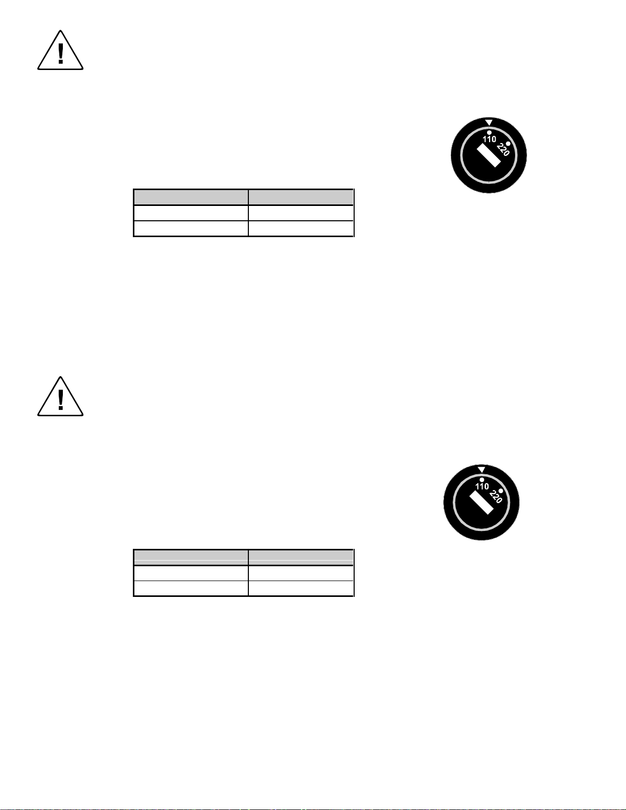
For Models with 110 / 220V Power Selector:
Caution: Before applying power to this unit, the voltage selector must be set to the appropriate setting to match local A/C line
voltage. Improper setting of the voltage selector may cause damage to the unit and create a potential fire hazard.
The voltage selector is a round switch located next to the A/C power input connector which looks
like this:
Using a straight slot screwdriver or small coin, rotate the selector to the correct position so that
the arrow lines up with 110 or 220 as appropriate for local power line voltage as indicated in the
chart below:
Local A/C Voltage Voltage Selector Setting
110 ~ 120 VAC 110
220 ~ 240 VAC 220
For all Models:
No serviceable parts inside the unit. Refer service to a qualified technician.
For Models with Internal or External Fuses:
For continued protection against fire hazard, replace only with same type and rating of fuse.
For IN2001 / IN3234 / IN3236 / IN3502 / IN3504 / IN3506 / IN3562 / IN3564 / IN3566 / IN3572 / IN3574 / IN3576:
Caution: Double pole / neutral fusing.
For all Models with Integral Lithium Battery:
Caution: Danger of explosion if battery is incorrectly replaced. Replace only with the same or equivalent type recommended by
the manufacturer. Dispose of used batteries according to the manufacturer’s instructions.
Instructions d’installation et de sécurité
Pour les modèles sans interrupteur de courant:
La prise de courant d’alimentation sera installé près de l’équipement et sera accessible.
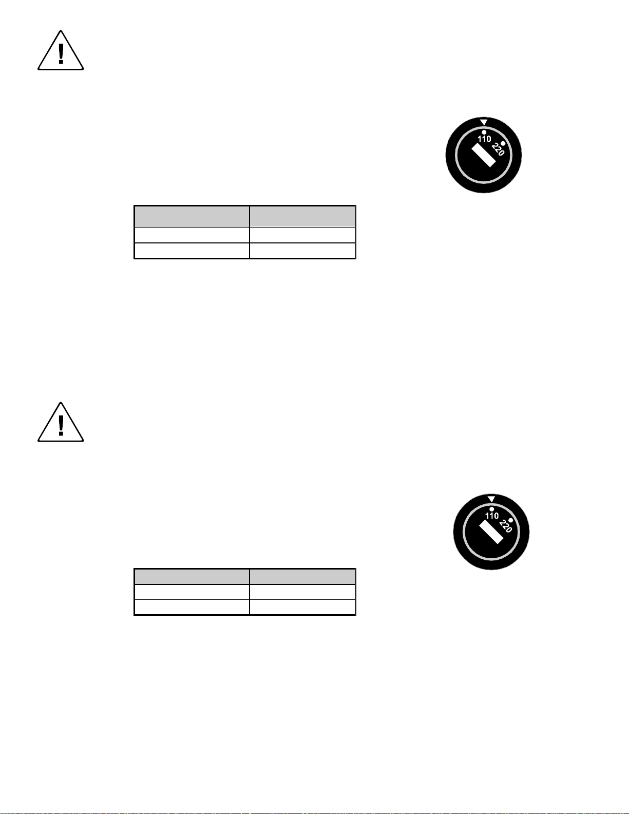
Pour les modèles avec un sélecteur d’alimentation 110V/220V:
Attention: Avant de connecter l’appareil au circuit d’alimentation, le sélecteur de courant doit être positionné sur la sélection
appropriée correspondant au voltage du circuit de courant alternatif local. Une mauvaise sélection peut engendrer des
dommages à l’appareil et créer un danger d’incendie.
Le sélecteur d’alimentation est un commutateur rond positionné près du connecteur
d’alimentation. Il se représente comme suit:
A l’aide d’un tourne-vis plat ou d’une pièce de monnaie, le sélecteur peut être tourné dans la
position adéquate en veillaut que la flèche corresponde avec 110 ou 220, en fonction de la
valeur du circuit de courant local. (Voir tableau ci-dessous)
Circuit local AC Position Sélecteur
110 ~ 120 VAC 110
220 ~ 240 VAC 220
Pour tout les modèles:
Pas de composants à entretenir à l’intérieur. Confiez toute réparation à un technicien qualifié.
Pour les modèles équipés de fusibles internes ou externes:
Afin d’éviter tout danger d’incendie, ne remplacer qu’avec le même type et la même valeur de fusible.
Pour IN2001 / IN3234 / IN3236 / IN3502 / IN3504 / IN3506 / IN3562 / IN3564 / IN3566 / IN3572 / IN3574 / IN3576:
Attention: Double pôle / fusible au neutre.
Pour tout les modèles avec une batterie au lithium interne:
Attention: Danger d’explosion si la batterie est incorrectement remplacée. Ne remplacez la batterie qu’avec le même modèle,
ou avec un modèle recommandé par le constructeur. Traitez les batteries usagées selon les instructions du fabricant, ou selon
les normes écologiques en viguer.
Page 3
Installations und Sicherheitshinweise
Für Geräte ohne Netzschalter:
Die Netzsteckdose soll in de Nähe des Gerätes installiert und frei zugänglich sein.
Für Geräte mit 110 / 220V Spannungswähler:
Achtung: Bevor Sie dem Gerät Spann ung zuführen, muß der Spannungswähler entsprechend der Spannung des lokalen
Wechselspannungsnetzes eingestellt werden. Die falsche Stellung des Spannungswählers
kann eine Beschädigung des Gerätes und möglicherweise ein Feuer verursachen.
Der Spannungswähler ist ein runder Schalter in der Nähe der Netzeingangsbuchse mit
folgendem Aussehen:
Drehen Sie den Wähler mit einem normalen Schraubenzieher oder einer kleinen Münze so, daß
der Pfeil auf die 110 oder 220 zeigt, entsprechend der Spannung Ihr es lokalen Netzes wie hier
angezeigt:
Lokale Netzwechselspannung Stellung des
110 ~ 120 V 110
220 ~ 240 V 220
Für alle Geräte:
Keine Wartung innerhalb des Gerätes notwendig. Reparaturen nur durch einen Fachmann!
Für Geräte mit interner oder externer Sicherung:
Für dauernden Schutz gegen Feuergefahr darf die Sicherung nur gegen eine andere gleichen Typs und gleicher Nennleistung
ausgewechselt werden.
Für IN2001 / IN3234 / IN3236 / IN3502 / IN3504 / IN3506 / IN3562 / IN3564 / IN3566 / IN3572 / IN3574 / IN3576:
Achtung: Allpolige Absicherung
Für alle Geräte mit eingebauter Lithium Batterie:
Achtung: Explosionsgefahr bei falschem Batterieeinsatz. Batterie nur erstzen durch den gleichen oder entsprechenden Typ
wie vom Hersteller empfohlen. Entsorgung verbrauchter Batterien nur nach den Anweisungen des Herstellers.
Spannungswählers
Instalacion E Instrucciones de Seguridad
Modelos Sin Interruptor:
La conexión debe ser instalada cerca del equipo y debe ser accesible.
Modelos con Selector de Voltaje de 110/220V:
Precaución: Antes de operar esta unidad, el selector de voltaje debe instalarse de forma que corresponda a la linea de voltaje
local. Instalación inadecuada del selector de voltaje puede causar daño a la unidad y originar un incendio.
El selector de voltaje es un cambia vía redondo localizado cerca de la conexión electrica, como se
ve en el dibujo:
Use un destornillador comun o una moneda pequeña, mueva el selector a la posición correcta, de
forma que las flechas indiquen 110 o 220 de acuerdo con el voltaje local, como esta indicado a
continuación.
Voltaje Local A/C Selector de Voltaje
110 ~ 120 VAC 110
220 ~ 240 VAC 220
Para Todos Los Modelos:
Dentro de la unidad , no hay partes para reparar. Llame un tecnico calificado.
Modelos con Fusibles Internos o Externos:
Para prevenir un incendio, reemplace solo con el mismo tipo de fusible.
Modelos IN2001 / IN3234 / IN3236 / IN3502 / IN3504 / IN3506 / IN3562 / IN3564 / IN3566 / IN3572 / IN3574 / IN3576:
Precaución: Double Polo / Fusible Neutral.
Modelos con Bateria de Lithiun Interna:
Precaución: Peligro de explosión si la batería es reemplacada incorrectamente. Reemplace solamente con la misma clase de
batería, o una equivalente recomendada por el fabricante. Deseche las baterías usadas de acuerdo con las instrucciones del
fabricante.
Page 4

CE COMPLIANCE
All products exported to Europe by Inline, Inc. after January 1, 1997 have been
tested and found to comply with EU Council Directive 89/336/EEC. These
devices conform to the following standards:
EN50081-1 (1991), EN55022 (1987)
EN50082-1 (1992 and 1994), EN60950-92
Shielded interconnect cables must be employed with this equipment to
ensure compliance with the pertinent Electromagnetic Interference (EMI)
and Electromagnetic Compatibility (EMC) standards governing this device.
FCC COMPLIANCE
This device has been tested and found to comply with the limits for a Class A
digital device, pursuant to Part 15 of the FCC rules. These limits are designed to
provide against harmful interference when equipment is operated in a
commercial environment. This equipment generates, uses and can radiate radio
frequency energy and, if not installed and used in accordance with the instruction
manual, may cause harmful interference to radio communications. Operation of
equipment in a residential area is likely to cause harmful interference, in which
case the user will be required to correct the interference at their own expense.
Page 5

DESCRIPTION
The IN3056 and IN3058 are high performance analog video distribution amplifiers designed for S-Video
signals. These units feature separate amplification circuitry for the chroma and luma video signal
components and 4-Pin mini DIN connectors for input and outputs. The IN3056 is a 1 input, 4 output
distribution amplifier and the IN3058 is a 1 input 8 output distribution amplifier. These units feature
high video bandwidth performance of 100 MHz and employ very compact designs which allow them to
be installed in a small space. The IN3056 / IN3058 include separate gain controls for the chroma and
luma signals which may be adjusted to compensate for signal loss caused by long cable runs. Multiple
IN3056/IN3058 units can be looped together to provide additional outputs.
COMPATIBILITY
The IN3056 / IN3058 are compatible with S-Video input signals in NTSC, PAL, and SECAM standards.
These units will also amplify and distribute one or two separate composite video signals if IN9093 S-
Video to 2-BNC adapters are used on the input and outputs.
1
INSTALLATION
An application diagram showing all connections is included on the next page.
1. Connect the video signal from the source to the IN3056 / IN3058 input.
2. Connect the IN3056 / IN3058 outputs to the display devices or other video output equipment.
3. Apply power to the unit (9 V 200 mA DC) using the supplied power adapter.
4. Adjust Chroma and Luma controls as needed (see Internal Controls section for details.)
It is very important to use good quality S-Video cables on all input and
output connections. Low cost S-Video cables often do not use coaxial cable
construction, and provide poor performance at distances greater than 6 to 12
feet. A better choice is an S-Video cable fabricated with two mini-coax
cables such as the IN8600 Series. For highest quality transmission on the
longest cable runs, a pair of high resolution coaxial cables (RG59 or better)
is recommended to carry the chroma and luma signal components. The
IN9093 S-Video male to 2-BNC female adapters may be used to adapt
regular BNC cables to the IN3056/IN3058 input and output connectors.
©1996-1997 - INLINE, INC. IN3056 / IN3058 OPERATION MANUAL - REV. 2. 3 02/19/00
Page 6

Application Diagram
IN3056
DVD Player
S-Video Output
IN8600 Series
S-Video Cables
S-VHS VCR
S-Video Input
Video Monitor
S-Video Input
Video Monitor
S-Video Input
Power Supply
9V / 200 mA
Video Projector
S-Video I nput
2
IN3056 / IN3058 OPERATION MANUAL - RE V. 2.3 02/19/00 ©1996-1997 - INLINE, INC.
Page 7
OPERATION
The IN3056 and IN3058 are designed to distribute and extend video signals in the S-Video (Y/C) format.
These units include controls for Chroma and Luma which can be used to optimize the output signal and
compensate for cable losses, extending a video signal as far as 300 feet without any degradation of the
signal. The actual usable drive distance depends greatly on the type of cable used for the long cable runs.
The Luma control affects the contrast, and the Chroma control adjusts the color level. Please note that
most display devices include an AGC circuit which automatically adjusts the Chroma level. In many
installations, no visible change of color saturation will be observed when adjusting the Chroma level
control because the AGC circuit in the display device is acting contrary to the level changes made by the
user to the IN3056 / IN3058 Chroma level control.
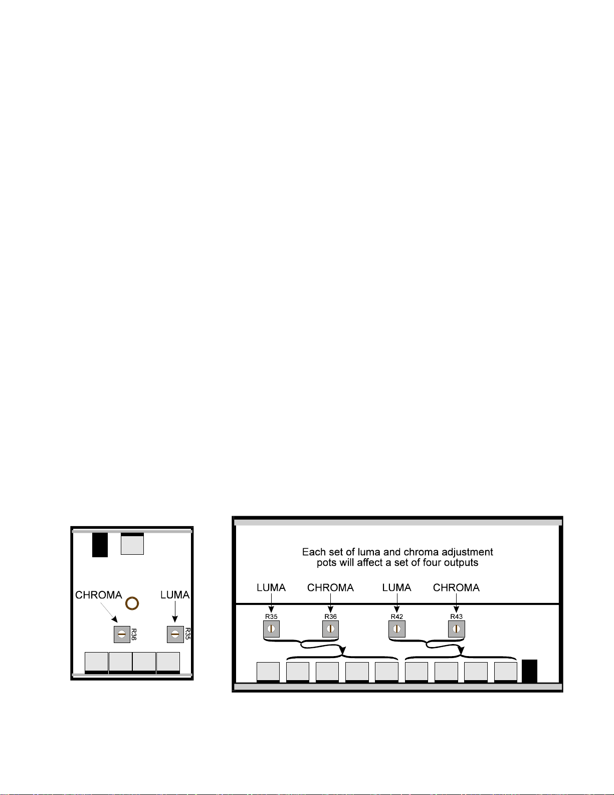
INTERNAL CONTROLS
The IN3056 and IN3058 internal Chroma and Luma level controls may be accessed using the following
procedure:
1. Remove the screw from the bottom of the unit.
3
2. Slide the top cover off.
3. Locate the Chroma and Luma controls (see diagrams below) and gently adjust as required
using a small plastic straight slot adjustment tool. Turn the controls counter-clockwise to
increase the gain and clockwise to decrease the gain. Note the following differences between the
two models:
IN3056 One Chroma Gain Control and One Luma Gain Control affect all four outputs
IN3058 Two Chroma Gain Controls and Two Luma Gain Controls are provided.
Each control affects four outputs (outputs 1 - 4 or outputs 5 - 8).
4. Replace the top cover and tighten the bottom screw.
©1996-1997 - INLINE, INC. IN3056 / IN3058 OPERATION MANUAL - REV. 2. 3 02/19/00
Page 8

4
SPECIFICATIONS
IN3056
1 x 4 S-Video Dist. Amp.
1 x 8 S-Video Dist. Amp..
IN3058
Input
Connector type (1) 4-Pin Mini DIN
Chroma / Luma Signals Analog, 1.5V p-p max., 75 ohm impedance
Output
Connector Type (4) 4-Pin Mini DIN (8) 4-Pin Mini DIN
Y/C Signals Analog Video, 75 ohm impedance
Bandwidth 100 MHz @ -3 dB
Rise and Fall Times 3.5 nano seconds
Controls
Chroma Gain Adjustable: 0.9 to 1.5
Luma Gain Adjustable: 0.9 to 1.5
Dimensions
Size 1" H x 3.5" W x 2.75" D 1" H x 7.75" W x 4" D
Weight 1 lb. 1 lb.
Power Consumption 9V 200 mA 9V 200 mA
Accessories Included
IN3056 Distribution Amplifier
9V 200 mA Power Supply
Operations Manual
IN3058 Distribution Amplifier
9v 200 mA Power Supply
Operations Manual
Optional Accessories
IN9093 Input/Output Adapter, 4-Pin Mini DIN Male to (2) BNC Female
TROUBLESHOOTING
Problem: There is no image on the output of the IN3056/3058.
Suggestions:
Problem: The output image is too dark.
Suggestion:
Problem: The output image is too bright or the picture blooms.
Suggestion:
IN3056 / IN3058 OPERATION MANUAL - RE V. 2.3 02/19/00 ©1996-1997 - INLINE, INC.
● Make sure the power supply is plugged in. Verify that the input and output cables are
connected and properly seated in the input and output connectors.
● Bypass the IN3056/3058 to ensure there is a video signal present.
● First make sure the display device contrast and brightness controls are set properly.
Then increase the appropriate IN3056/3058 Luma gain control(s) until the desired image
is achieved.
● First make sure the display device contrast and brightness controls are set properly.
If necessary, adjust the appropriate IN3056/3058 output Luma gain control(s) until the
desired image is achieved.
Page 9

Problem: The output image is not sharp enough. Vertical lines are very thin.
Suggestions:
● Make sure you are using high quality coaxial video cables such as the Inline IN8600
Series, especially for longer cable runs. Many low cost S-Video cables are not
constructed using coaxial cable and will not transmit signals well at distances over
6 to 12 feet.
WARRANTY
♦
Inline warrants the equipment it manufactures to be free from defects in materials and
workmanship.
♦
If equipment fails because of such defects and INLINE is notified within two (2) years from the
date of shipment, INLINE will, at its option, repair or replace the equipment at its plant, provided
that the equipment has not been subjected to mechanical, electrical, or other abuse or
modifications.
♦
Equipment that fails under conditions other than those covered will be repaired at the current
price of parts and labor in effect at the time of repair. Such repairs are warranted for ninety (90)
days from the day of re-shipment to the Buyer.
♦
This warranty is in lieu of all other warranties expressed or implied, including without
limitation, any implied warranty or merchantibility or fitness for any particular purpose,
all of which are expressly disclaimed.
5
The information in this manual has been carefully checked and is believed to be accurate. However,
Inline, Inc. assumes no responsibility for any inaccuracies that may be contained in this manual. In no even t
will Inline, Inc. be liable for direct, indirect, special, incidental, or consequential damages resulting from any
defect or omission in this manual, even if advised of the possibility of such damages. The technical information
contained herein regarding IN3056 / IN3058 features and specifications is subject to change without notice.
All trademarks and brands are property of their respective companies.
All Rights Reserved © Copyright 1996-1997
©
(800) 882-7117 ♦ (714) 450-1800 ♦ FAX (714) 450-1850
INLINE, INC ♦ 810 West Taft ♦ Orange, CA 92865
♦ www.inlineinc.com
©1996-1997 - INLINE, INC. IN3056 / IN3058 OPERATION MANUAL - REV. 2. 3 02/19/00
 Loading...