

Page 1
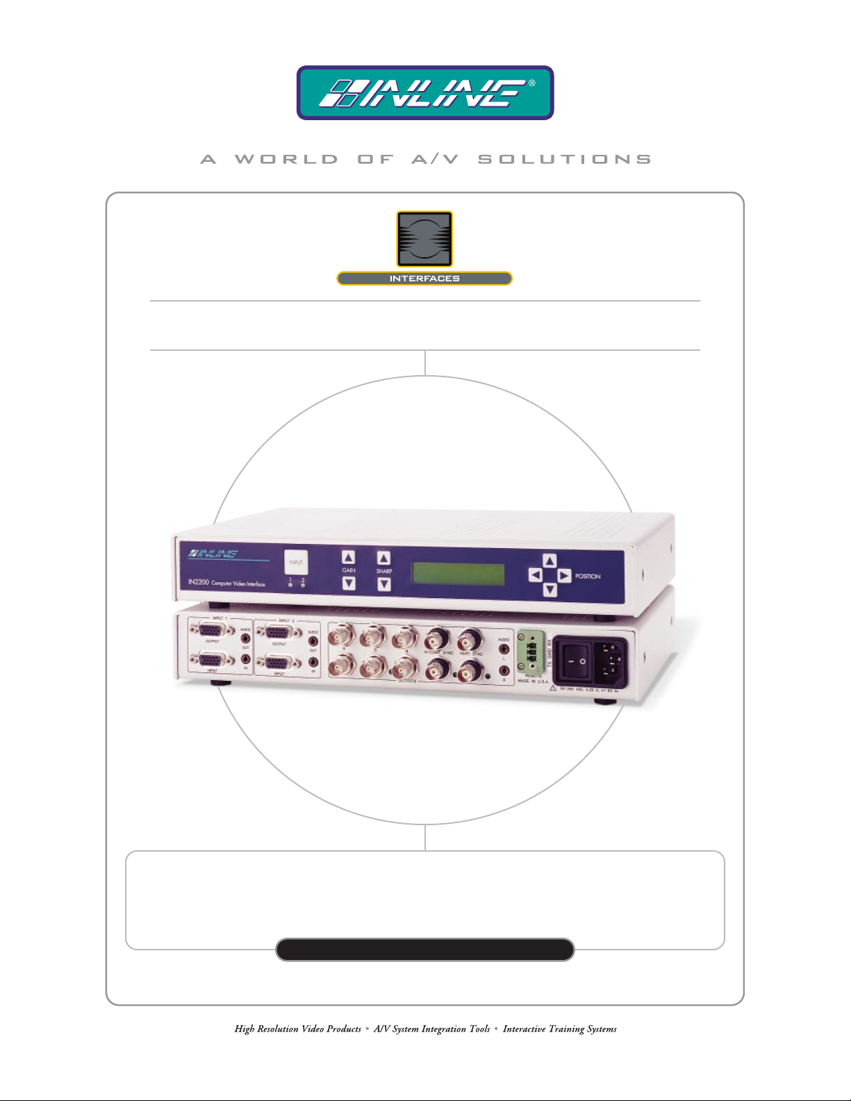
TWO INPUTS, TWO OUTPUTS AND RS–232 SERIAL CONTROL
COMPUTER INTERFACE WITH
IN2200RS
IN2200RS
OPERATION MANUAL
Page 2
Installation and Safety Instructions
For Models without a Power Switch:
The socket outlet shall be installed near the equipment and shall be accessible.
For all Models:
No serviceable parts inside the unit. Refer service to a qualified technician.
For Models with Internal or External Fuses:
For continued protection against fire hazard, replace only with same type and rating of fuse.
Instructions d’installation et de sécurité
Pour les modèles sans interrupteur de courant:
La prise de courant d’alimentation sera installé près de l’équipement et sera accessible.
Pour tout les modèles:
Pas de composants à entretenir à l’intérieur. Confiez toute réparation à un technicien qualifié.
Pour les modèles équipés de fusibles internes ou externes:
Afin d’éviter tout danger d’incendie, ne remplacer qu’avec le même type et la même valeur de fusible.
Installations- und Sicherheitshinweise
Für Geräte ohne Netzschalter:
Die Netzsteckdose soll in der Nähe des Gerätes installiert und frei zugänglich sein.
Für alle Geräte:
Keine Wartung innerhalb des Gerätes notwendig. Reparaturen nur durch einen Fachmann!
Für Geräte mit interner oder externer Sicherung:
Für dauernden Schutz gegen Feuergefahr darf die Sicherung nur gegen eine andere gleichen Typs und gleicher Nennleistung
ausgewechselt werden.
Instalacion E Instrucciones de Seguridad
Modelos Sin Interruptor:
Para Todos Los Modelos:
Modelos con Fusibles Internos o Externos:
La conexión debe ser instalada cerca del equipo y debe ser accesible.
Dentro de la unidad , no hay partes para reparar. Llame un tecnico calificado.
Para prevenir un incendio, reemplace solo con el mismo tipo de fusible.
CE COMPLIANCE
All products exported to Europe by Inline, Inc. after January 1, 1997 have been tested and found to
comply with EU Council Directive 89/336/EEC. These devices conform to the following
standards:
EN50081-1 (1991), EN55022 (1987)
EN50082-1 (1992 and 1994), EN60950-92
Shielded interconnect cables must be employed with this equipment to ensure compliance with
the pertinent Electromagnetic Interference (EMI) and Electromagnetic Compatibility (EMC)
standards governing this device.
FCC COMPLIANCE
This device has been tested and found to comply with the limits for a Class A digital device,
pursuant to Part 15 of the FCC rules. These limits are designed to provide against harmful
interference when equipment is operated in a commercial environment. This equipment generates,
uses and can radiate radio frequency energy and, if not installed and used in accordance with th e
instruction manual, may cause harmful interference to radio communications. Operation of
equipment in a residential area is likely to cause harmful interference, in which case the user will be
required to correct the interference at their own expense.
Page 3

Table of Contents
Product Overview....................................................................................................................2
Description............................................................................................................................2
Compatibility ...........................................................................................................................3
Input......................................................................................................................................3
Output...................................................................................................................................3
Installation................................................................................................................................4
Adapter / Extension Cables for Input and Local Monitor Output ........................................5
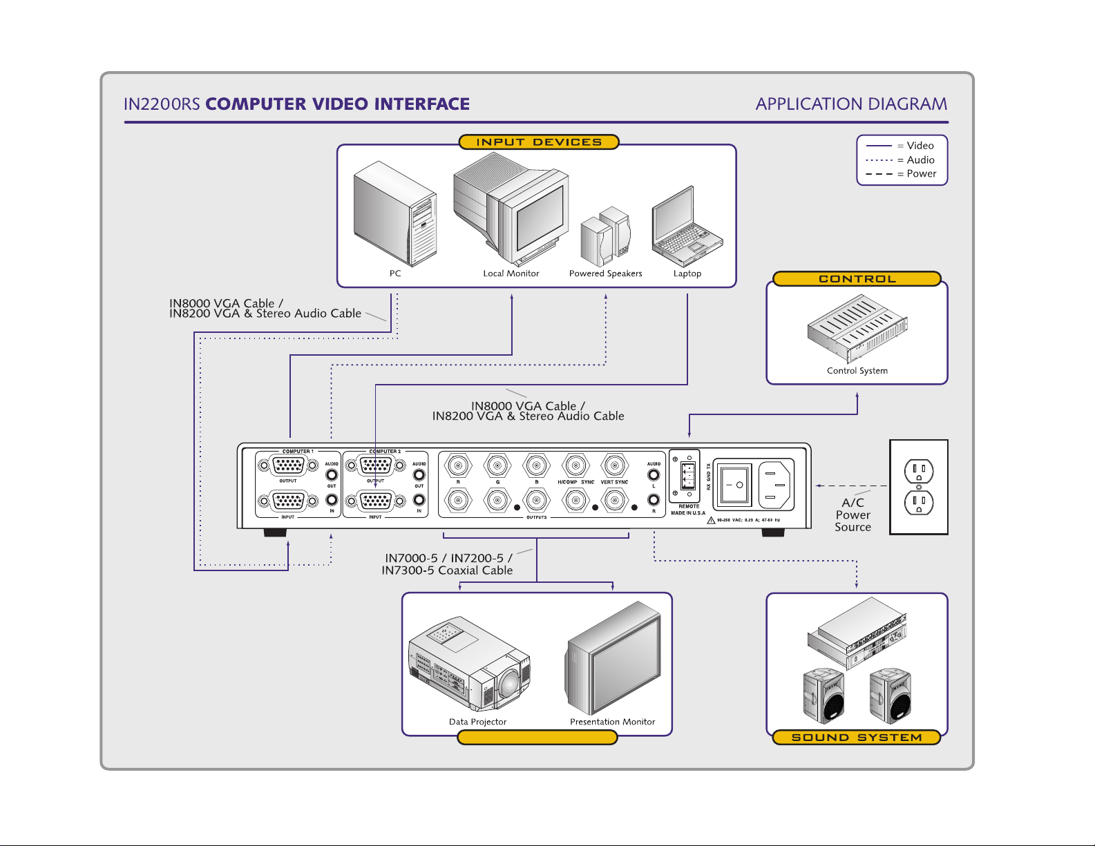
IN2200RS Application Diagram..........................................................................................6
Front Panel Controls.............................................................................................................7
Rear Panel Connectors..........................................................................................................7
Operation..................................................................................................................................8
Input......................................................................................................................................8
LCD Display.........................................................................................................................8
Gain ......................................................................................................................................8
Sharpness..............................................................................................................................8
Position.................................................................................................................................9
Screen Shift...........................................................................................................................9
Front Panel Disable ..............................................................................................................9
Automatic Input Selection....................................................................................................9
Status / Mode Information....................................................................................................9
Dipswitch Settings................................................................................................................9
Optimal Settings for LCD / DMD / D-ILA / Plasma Displays...........................................11
Power-up Settings..................................................................................................................11
IN2200RS Power-up Options.............................................................................................11
Reset to Factory Default.....................................................................................................12
Remote Control Operation...................................................................................................11
RS-232 Control...................................................................................................................12
IN2200RS Serial Commands.............................................................................................13
Serial Command Examples.................................................................................................15
Stereo Audio Switching.........................................................................................................16
Input and Local Monitor Output.........................................................................................16
Main Audio Output.............................................................................................................16
IN2200RS Internal Controls.................................................................................................17
IN2200RS Internal Controls Diagram................................................................................18
Specifications..........................................................................................................................19
Troubleshooting.....................................................................................................................20
IN2200RS Deluxe Computer Interface Kit.........................................................................22
Warranty................................................................................................................................23
Page 4
2
Product Overview
DESCRIPTION
The IN2200RS is a high-performance video interface for analog video signals including VGA,
SVGA, XGA, SXGA, UXGA, MAC, SUN, SGI and other high-resolution workstations. The
IN2200RS includes an impressive range of features and signal adjustments, yet retains a clean,
uncluttered appearance and amazingly simple operation.
The IN2200RS is not
other output device must be compatible with the horizontal scan rate,
vertical scan rate and resolution output by the computer video card.
• Two Video Inputs with Local Monitor Outputs - offer flexibility in a variety of
applications.
• 32 Memories - When an input is selected, previously stored position, gain and sharpness
settings for that input are automatically recalled.
• Three Switching Modes - In Manual Mode, users select the desired input by pressing a
large front panel input button. In Auto Switch Mode, the unit automatically selects the
active input. If more than one input is active, the highest numbered input has priority.
Remote Switching is done via RS-232 control.
• RS-232 Serial Control - is provided for all interface functions and facilitates complete
system integration and effortless control when combined with a third party control
system.
• Stereo Audio-Follow-Video Switching - When Input 1 or 2 is selected, the video signal
and the associated stereo audio signal are simultaneously switched to the output.
• Large Backlit LCD Display - simultaneously shows the horizontal and vertical
frequencies of the current input signal.
• 15-Pin HD VGA Standard Connectors - The IN2200RS connects directly to VGA
graphics cards and VGA local monitors.
• High-Resolution Amplification - The IN2200RS provides superb performance with
analog video signals at virtually any resolution and refresh rate.
• Output Sync Optimization - Dipswitches set the interface output sync signals for
optimal operation with LCD, DMD, D-ILA and Plasma Data Grade Display devices.
• Flexible Output Sync with Automatic Output Sync Selection - The unit can be set for
an RGBHV, RGBS or RGsB output signal to match the requirements of the data display
device and signal distribution system.
a scan converter. The data projector, monitor or
IN2200RS Operation Manual - V1.1 01/03/2001 ©2001 - INLINE, Inc.
Page 5

3
• Screen Shift - slowly moves the image on the CRT or Plasma Display device to reduce
video “burn-in” (when displaying static images).
• Gain Control - can be adjusted to boost the signal voltage and provides a smooth fade to
black.
• Sharpness Control - provides image enhancement for high-resolution video signals by
increasing clarity and image detail, and compensates for signal loss during long cable runs.
• Horizontal and Vertical Position Controls - provide precise positioning of the image
within the data display area.
• Easy Operation - The IN2200RS offers an exceptional variety of controls and signal
adjustments, yet remains very easy for non-technical personnel to operate.
• 300 MHz Video Bandwidth
• Rack Mountable
Compatibility
INPUT
The IN2200RS will accept high-resolution video signals from virtually any computer that outputs
an analog video signal. The unit will work with signals at virtually any resolution and refresh
rate. Compatible computer video signals include VGA, SVGA, XGA, SXGA, UXGA, MAC,
SUN, SGI and other high-resolution computers outputting an analog video signal. Input signal
compatibility parameters are:
Video Signal: Analog RGB Video
Signal Format: RGBHV, RGBS, RGsB
Horizontal Frequency Range: 30 KHz to 130 KHz
Vertical Refresh Rates: 30 Hz to 120 Hz
OUTPUT
The output signal of the IN2200RS is analog RGB video with TTL sync on 3, 4 or 5 female BNC
connectors. The output format can be set to RGBHV, RGBS or RGsB using dipswitches. This output
signal is compatible with high-resolution data grade monitors and data / graphics projectors.
VGA, MAC, SUN, SGI and other high-resolution workstations operate in
several video modes encompassing a wide range of resolutions and scan rates.
Many of the video signals from the newest models can run as high as 70 KHz or
more, with the newest VGA cards offering an output resolution of 1600 x 1200
(some can even go as high as 1920 x 1080). The data projector or monitor
connected to the interface output must be compatible with the horizontal scan
rate and vertical refresh rate of the computer’s video signal. Please check the
documentation for both the computer graphics card and the data display device
to ensure compatibility
©2001 - INLINE, Inc. IN2200RS Operation Manual - V1.1 01/03/2001
Page 6

4
Installation
This section offers step-by-step instructions for installing the IN2200RS. An Application
Diagram is provided on page 6. Illustrations showing Front Panel Controls and Rear Panel
Connectors can be found on page 7.
1. Place / install the IN2200RS at the desired location. Make sure that the unit is seated on
a flat surface or is securely installed in a standard 19” equipment rack in a 1-U rack space
(using the optional IN9129 Rack Ears).
2. Set the dipswitches for the requirements of your installation (see the Dipswitch Settings
Chart on page 10).
3. Connect the IN2200RS video output (5 BNC connectors) to the data display device’s
RGB input using high-resolution BNC cables or a multi-conductor RGBHV, RGBS or RGsB
“snake.” The IN7000 Series, IN7200 Series, IN7300 Series and IN7400 Series highresolution cables are well suited for this purpose. While making connections, take care to
ensure that the red output is connected to the red input, green output is connected to the green
input, etc.
4. Connect the IN2200RS main audio outputs (3.5mm female jacks for left and right channel
signals) to the audio system’s input (mixer or amplifier). The main audio output signal is line
level and can be set for unbalanced (factory default) or balanced. The output is compatible
with any audio system that accepts a line level signal, and can be easily connected with an
IN9106 audio cable. For audio systems with RCA connectors, use the IN9017 audio adapter
cable.
Note: Cable wiring configurations for balanced / unbalanced output signals and internal
control adjustments can be found on pages 16 & 17.
5. Connect the computer graphics card to the IN2200RS 15-pin video input port.
• PC / MAC / SGI Computers with 15-pin HD Video Ports - can be connected via
IN8000M-1 / IN8200M-1 Series high-resolution coaxial VGA cables.
• Older Macintosh (15-pin D) / SUN (13W3) / Workstations (4 or 5 BNC) - can be
connected using the appropriate input / output cables listed in the chart on the following
page.
6. Connect the computer sound card output (if applicable) to the IN2200RS 3.5mm female
stereo audio input connector using an IN8200-1 Series cable [15-pin HD with 3.5mm (M-M)
mini DIN], or an IN9106 audio patch cable (3.5mm stereo mini male to 3.5mm stereo mini
male). For computers with RCA connectors, use the IN9107 audio adapter cable [(1) 3.5mm
stereo mini male to (2) RCA male].
7. Connect the local computer monitor (if present) to the local monitor output port of the
IN2200RS. Monitors with 15-pin VGA connectors will attach directly to the interface. For
other types of monitors, use the appropriate monitor output adapter cable (see the list on the
following page). If no local monitor is used, set the monitor emulation dipswitch to emulate
a color VGA or 13/14” MAC RGB monitor (see the Dipswitch Settings chart on page 10).
IN2200RS Operation Manual - V1.1 01/03/2001 ©2001 - INLINE, Inc.
Page 7
5
Check the monitor emulation chart and dipswitch settings carefully. An
inappropriate setting of the emulation dipswitches may lead to improper
operation and could even result in severe damage to the computer video
port or the monitor. If users are in doubt as to which monitor emulation to
choose, set all the Monitor Emulation dipswitches to “0” and connect the
local monitor.
8. Connect powered local speakers and / or recording devices to the local audio outputs (if
applicable).
9. Connect power to the IN2200RS using the IN9230 IEC power cable (included).
10. Complete the installation by turning on all computers, local monitors, powered speakers,
data display devices, the IN2200RS and the audio system.
ADAPTER / EXTENSION CABLES FOR INPUT AND LOCAL MONITOR OUTPUT
The IN2200RS has 15-pin HD VGA-type input and local monitor output connector ports. The
following cables / adapters are available:
Computer 3’ 6’ 12’ 25’ 35’ +
VGA: 15-Pin HD
Input Cable (M-M)
Output Cable (M-F)
VGA with Stereo Audio: 15-Pin HD with 3.5mm (M-M) mini DIN
Input Cable (M-M)
Output Cable (M-F)
MAC with 15-Pin D:
Input Cable (M-M)
Output Cable (M-F)
MAC G3, G4 and PowerBook with 15-Pin HD*:
Input Cable (M-M)
Output Cable (M-F)
SUN: 13W3 (may also be used with SGI with RGsB output)
Input Cable (M-M)
Output Cable (M-F)
Workstation: 5 BNC / RGBHV
Input Cable (M-M)
Output Cable (M-M)
Workstation: 4 BNC / RGBS
Input Cable (M-F)
*Newer Mac G3 models (with translucent cases) have 15-Pin HD connectors (pins arranged in 3 rows).
Older G3 models (with solid white enclosures) incorporate 15-Pin D connectors (pins arranged in 2 rows).
IN8003M-1 IN8006M-1 IN8012M-1 IN8025M-1 IN80xxM-1
IN8006-1 IN8012-1 IN8025-1 IN80xx-1
IN8203M-1 IN8206M-1 IN8212M-1 IN8225M-1 IN82xxM-1
IN8203-1 IN8206-1 IN8212-1 IN8225-1 IN82xx-1
IN9140M IN9144M
IN9141 IN9145
IN8006M-1 IN8012M-1 IN8025M-1 IN80xxM-1
IN8006-1 IN8012-1 IN8025-1 IN80xx-1
IN9142M IN9146M
IN9143 IN9147
IN9045-L6 IN9045-L12 IN9045-L25 IN9045-Lxx
IN9045-L6 IN9045-L12 IN9045-L25 IN9045-Lxx
IN9100
©2001 - INLINE, Inc. IN2200RS Operation Manual - V1.1 01/03/2001
Page 8
6
IN2200RS Operation Manual - V1.1 01/03/2001 ©2001 - INLINE, Inc.
output devices
Page 9

7
©2001 - INLINE, Inc. IN2200RS Operation Manual - V1.1 01/03/2001
Page 10

8
Operation
INPUT
The Input Button can be used to select Input 1 or Input 2. Each time the button is pressed, the
unit toggles back and forth between the two inputs, and the appropriate front panel LED indicator
illu-minates to show the current channel selection. Unique gain, sharpness, horizontal position
and vertical position settings are automatically stored for each input and recalled each time the
input is selected.
The non-selected channel is terminated into 75 Ohms. The interface automatically returns to the
last selected channel if power is removed and reapplied to the unit. Input channels may also be
selected remotely by using a third-party controller.
LCD DISPLAY
The LCD displays the horizontal and vertical scan rates and provides adjustment status feedback.
When an adjustment is being made, the LCD shows a description of the function and a bar graph
to indicate the current location within the adjustment range. The LCD remains in this state for
several seconds after the last change and then reverts to the horizontal and vertical scan rate
display.
GAIN
Gain (¾ and ¿) Buttons adjust the output voltage of the red, green, and blue outputs
simultaneously (ensuring that gray scale is maintained), and may be used to compensate for
signal loss due to long cable runs. The gain adjustment range is 0 in the minimum position (no
video information) and 1.3 in the maximum position (30% increase). The factory default setting
is 1.0 (unity gain). Operators can press and release the button for small changes or press and hold
for major changes. The Gain Control can also be used to fade the image to black.
SHARPNESS
Sharp (¾ and ¿) Buttons provide variable high-frequency equalization that can compensate for
signal loss due to long output cable runs. Careful optimiz ation of the sharpness control will result
in a greatly enhanced image with increased clarity and edge detail. The amount of high
frequency boost required for each display system will vary depending on the length and
bandwidth performance of the video output cables, and, to a lesser extent, the resolution and
frequency of the input signal. When using short output cables, the sharpness control should
usually be placed at the minimum setting to avoid over-peaking.
Operators can press and release the sharpness control button for subtle changes or press and hold
for major adjustments. The factory default setting is minimum (no sharpness / peaking
enhancement). The following guidelines are useful in selecting the optimal sharpness / peaking
setting:
If the image is soft and / or fine details in the picture lack clarity:
The sharpness is probably set too low. Increase the sharpness control setting.
If a white, ghosted image appears to the right side of the lines / characters:
The sharpness is probably set too high (over-peaked). Decrease the sharpness control
setting.
IN2200RS Operation Manual - V1.1 01/03/2001 ©2001 - INLINE, Inc.
Page 11

9
POSITION
The Position (¾,¿,½&¼) Arrows shift the video image in the designated direction. Operators can
press and release a button for small shifts or press and hold for large shifts. If the horizontal or
vertical positioning controls are disabled, the LCD display indicates the current status when the user
tries to adjust them.
SCREEN SHIFT
This function is enabled / disabled by pressing the GAIN (¾ / ¿) Button during power-up.
When enabled, the image is slowly shifted in a clockwise motion to help prevent CRT or Plasma
display “burn-in.” A complete list of power-up options is provided on page 11.
Shift Range: The amount that the image is shifted can be set to “High” or “Low” during
the power-up sequence. The High Range is set by pressing and holding the
POSITION (½) Button while turning on the power. The Low Range is set
similarly but holding the POSITION (¼) Button while turning on the power.
Shift Speed: When adjusting the size of the display it is important to allow for the shift
range. Therefore, there is a Fast Screen Shift Speed, which rapidly moves
through the entire shifting range (so users don't have to wait a long time for
the image to make a complete cycle), and a Slow Screen Shift Speed. The
Fast Screen Shift is set by holding the SHARP (¾) Button during power-up,
and the Slow Shift Speed is set by holding the SHARP (¿) Button.
FRONT PANEL DISABLE
The front panel is disabled / enabled with a dipswitch setting (#5 of Dipswitch Bank 2). When
the front panel is disabled, none of the front panel buttons operate. The LCD display will read
“Front Panel Disabled” whenever a front panel button is pressed. However, input selection can
still be made via the remote port or by setting the unit for Automatic Input Selection.
AUTOMATIC INPUT SELECTION
The IN2200RS can be set to automatically select the active input. An input is considered active if
it has a sync signal, or if pin 10 is grounded (usually done through the presence of an input cable,
regardless of whether or not a sync signal is present). If both inputs are active, Input 2 has priority.
If there is no active input signal (or pin 10 is not grounded) on Input 2, Input 1 is the default.
Note: When set to the Automatic Input Selection mode, the front panel and remote input selection
features are disabled. Dipswitch #6 on Bank 2 enables / disables the Automatic Input Select mode.
STATUS / MODE INFORMATION
Each time the unit is powered up, the LCD displays a sequence of screens to inform the user of how
the IN2200RS interface is configured. These screens show the following items: Automatic Input
Selection Enabled / Disabled, Front Panel Enabled / Disabled, Screen Shift Settings and the Output
Sync Format.
DIPSWITCH SETTINGS
Two dipswitch panels are easily accessed through windows on the bottom of the IN2200RS.
SWITCH 1 regulates the output sync format. SWITCH 2 determines the monitor emulation settings.
For most installations, the IN2200RS will be operated in the factory
default mode and will not require any changes to the dipswitch settings.
©2001 - INLINE, Inc. IN2200RS Operation Manual - V1.1 01/03/2001
Page 12

10
Switch Panel #1
Switch Function Setting Description
1 Reserved None
2
3
4
5
6
7
8
9
Output Sync Format
Horizontal Position
Control
Vertical Position Control
Output Sync Format (#2
must be set to 0)
Output Sync Format (#5
must be set to 1)
Output Sync Polarity
(RGBHV In / Out only)
Output Sync Polarity
(RGBHV In / Out only)
RGBS / RGsB Output
serration pulses
1* Auto
Sync format is set automatically based on the number of cables
connected to the unit
0 Manual Sync format is set via switches #5 & #6
1 Off Disable horizontal position control
0* On Enable horizontal position control
1 Off Disable vertical position control
0* On Enable vertical position control
1* RGBS/
RGBHV
Sync format is RGBS or RGBHV depending on the setting of
dipswitch #6
0 RGsB Sync format is sync on green (RGsB)
1 RGBS Sync format is RGBS
0* RGBHV Sync format is RGBHV
1* Forced
(see #8)
0 Mirror
Input
1* Negative
0 Positive
1 Remove
0* Present
With RGBHV input signal and RGBHV output signal, the H &
V sync polarities are set with dipswitch #8
With RGBHV input signal and RGBHV output signal, the V &
H sync polarities are the same as the input
With RGBHV input signal and RGBHV output signal, the H &
V sync polarities are negative, negative
With RGBHV input signal and RGBHV output signal, the H &
V sync polarities are positive, positive
The output sync will not have serration pulses when set for
RGBS or RGsB output
The output sync will have serration pulses present when set for
RGBS or RGsB output
10 Reserved None
Switch Panel #2:
Switch Function Setting Description
1
2
3
4
5
6
Input 1 Monitor
Emulation
Input 1 Auto
Emulation
Input 2 Monitor
Emulation
Input 2 Auto
Emulation
Front Panel
Operation
Automatic Input
Selection
1 Emulation On Monitor emulation is always ON for Input 1
0* Automatic
Monitor emulation is automatic. Emulation is ON when there
is no local monitor present and of f when there is a local
monitor (switch #2 must be ON)
1 Off Disable Auto Emulation
0* On Enable Auto Emulation (switch #1 must be set to 0 )
1 Emulation On Monitor emulation is always ON for Input 1
0* Automatic
Monitor emulation is automatic. Emulation is ON when there
is no local monitor present and of f when there is a local
monitor (switch #2 must be ON)
1 Off Disable Auto Emulation
0* On Enable Auto Emulation (switch #1 must be to 0 )
1* Enable Enable the front panel operation
0 Disable Disable the front panel
1 On
An input is selected automatically based on the presence of
sync. Input 2 has the higher priority
0* Off Manual input selection
7 Reserved None
8 Reserved None
9 Reserved None
10 Reserved None
* Factory Default
IN2200RS Operation Manual - V1.1 01/03/2001 ©2001 - INLINE, Inc.
Page 13

11
OPTIMAL SETTINGS FOR LCD / DMD / D-ILA / PLASMA DISPLAYS
Output Sync Format – The IN2200RS interface features advanced sync processing circuitry that
offers superb compatibility with a wide range of display devices. The IN2200RS has been
designed (and extensively tested) to provide excellent operation w hen set for RG BH V, R GB S and
RGsB output signal formats. However, some display devices most readily identify and display
VGA-type signals when they are in the RGBHV signal format. For this reason, users may
achieve optimal compatibility and more consistent results when the interface is set to the factory
default output sync format of RGBHV (see Dipswitch Settings on the previous page).
Horizontal Position Control - The IN2200RS horizontal position control utilizes a new circuit
design that provides excellent image quality and greatly enhanced compatibility with a variety of
data display technologies. However, in rare cases, instability in parts of the displayed image may
still occur (depending on the design of the display device’s sync circuitry). Adjusting the data
display’s fine phase or auto phase adjustment will usually alleviate the problem. If problems
persist, users may wish to disable the IN2200RS horizontal position control (see Dipswitch
Settings).
The following output sync settings provide maximum sync signal preservation and are
recommended for the best image quality with LCD, DMD, D-ILA and Plasma Display devices:
DIPSWITCH PANEL #1:
Dip Switches ON: 3 & 5
Signal Format: Red / Green / Blue / Horizontal and Vertical Sync
Horizontal Position Control: Disabled
H & V Sync Polarity: Mirror Input Polarities
Power-up Settings
Depressing certain front panel switches during power-up will change certain parameters. To
access power-up adjustments, depress a specific button while turning the unit's power switch to
ON. If power is already on, hold down the indicated button and switch the power off, and then
back on. These settings are retained until they are changed by serial commands, during
subsequent power-ups, or by resetting the unit to factory default.
IN2200RS POWER-UP OPTIONS
POSITION DOWN Factory Default Reset
POSITION UP
POSITION LEFT Set Screen Shift to Low Range
POSITION RIGHT Set Screen Shift to High Range (factory default)
GAIN DOWN Disable Screen Shift (factory default)
GAIN UP Enable Screen Shift
SHARP DOWN Set Screen Shift to Slow Speed
SHARP UP Set Screen Shift to Fast Speed (factory default)
©2001 - INLINE, Inc. IN2200RS Operation Manual - V1.1 01/03/2001
Page 14

12
RESET TO FACTORY DEFAULT
The IN2200RS can be reset to factory default by holding the Position (¿) Button while applying
power to the unit. The factory default values are:
• gain is set to 185 of 255 • screen shift speed is fast
• sharpness is set to 126 of 255 • screen shift range is high
• horizontal video position is set to 155 of 255 • baud rate is set to 9600
• vertical video position is set to 148 of 255 • command code is set to [ ]
• screen shift is enabled
Remote Control Operation
RS-232 CONTROL
The IN2200RS RS-232 serial control port accepts serial commands from a control system, computer serial port, or any other device capable of sending out serial ASCII commands at compatible
baud rates. A complete listing of RS-232 command codes is included on the pages 13 & 14.
Communication Protocol:
♦ 8 data bits
♦ 1 stop bit
♦ No parity check
♦ 9600 baud (factory default setting)
Baud Rate Selection:
The IN2200RS has a factory default baud rate of 9600 bps and can communicate at rates from
2400 up to 38,400. Baud rates can be selected using the ACxx Serial Commands listed on the
following page.
Note: The baud rate transmitted must
Command Code Structure and Delimiters:
All commands sent to the unit must contain a leading code, the command code, and an ending
code. Each command must be completely executed before the unit will accept a new command.
The IN2200RS can be set to recognize five sets of leading and end codes (delimiters) when using
an RS-232 remote: parentheses ( ), brackets [ ], braces{ }, slashes \ /, and less and greater than
< >.
The factory default serial delimiters are [ ].
Note: Only the IN2200RS that has the same delimiters as the remote controller will respond.
A complete command consists of:
[ The leading code
CH2 The command code.
] The ending code
Example: [CH2] sets the IN2200RS to select channel 2.
match the baud rate selected on the IN2200RS.
IN2200RS Operation Manual - V1.1 01/03/2001 ©2001 - INLINE, Inc.
Page 15

13
Serial Control Cable Wiring:
When controlling only one IN2200RS unit, connect the RS-232 cable as follows:
Controller Transmit to IN2200RS Receive
Controller Ground to IN2200RS Ground
Controller Receive to IN2200RS Transmit
When controlling multiple IN2200RS units, connect the RS-232 cable as follows:
Controller Transmit to Each IN2200RS Receive
Controller Ground to Each IN2200RS Ground
Controller Receive to Only one IN2200RS Transmit
When controlling multiple units, the Controller Receiver Terminal must
connect to only one IN2200RS Transmit Terminal. Multiple IN2200RS
Transit Lines may not be connected together, otherwise signal contention
from multiple units will result. Therefore, “receive” information is only
available from one IN2200RS in this configuration. Each unit must be set
to different delimiters.
IN2200RS SERIAL COMMANDS♦
COMMAND DESCRIPTION COMMAND DESCRIPTION
AC14 set serial baud rate to 2400
AC15 set serial baud rate to 4800
AC16
AC17 set serial baud rate to 19,200
AC18 set serial baud rate to 38,400
CALLxx recall current setting from configura-
CH1 set channel 1*
set serial baud rate to 9600♦♦
tion memory (01 <= xx <=32) settings
include:
Channel
Channel 1 Gain
Channel 2 Gain
Channel 1 Sharpness
Channel 2 Sharpness
Channel 1 Vertical Position
Channel 2 Vertical Position
Channel 1 Horizontal Position
Channel 2 Horizontal Position
baud rate and command code are
general and are not saved for each
memory
CH2 set channel 2*
CH? request current channel
CMDCD0
CMDCD1 set command code { }
CMDCD2 set command code ( )
CMDCD3 set command code < >
CMDCD4 set command code \ /
GAIN+ set gain (increment)
GAIN- set gain (decrement)
GAIN@ set gain (factory default is defined in
GAINxxx set gain (absolute within limits
defined in in2200.h)
GAIN? request current gain value
HSC? request horizontal scan rate
(example response is [123456 Hz])
INFO send unit version
PH- imag e shift le ft***
PH+ image shift right***
PH@ set horizontal image position to
set command code [ ]♦♦
in2200.h)
normal***
©2001 - INLINE, Inc. IN2200RS Operation Manual - V1.1 01/03/2001
Page 16

14
COMMAND DESCRIPTION COMMAND DESCRIPTION
PHxxx set horizontal image position to
absolute***
PH? request current horizontal image
position
PV+ image shift up**
PV- image shift down**
PV@ set vertical image position to
normal**
PVxxx set vertical image position to
absolute**
PV? request current vertical image
position
RES0 reset (power on)
(the channel, gain, sharpness, video
RES1
position, baud rate and command
codes are reset to their most recent
EEPROM values
reset ♦♦
1) the gain, sharpness and video
position for both channels 1 & 2
are reset to their factory default
values
2) screen shift parameters, baud rate
and command codes are reset to
their factory default values
3) all configuration memories are ini-
tialized with factory default values
4) channel 1 is selected
SAVExxx save current settings to configuration
memory (01 <= xx <= 32) settings
include:
Channel
Channel 1 Gain
Channel 2 Gain
Channel 1 Sharpness
Channel 2 Sharpness
Channel 1 Vertical Position
Channel 2 Vertical Position
Channel 1 Horizontal Position
SHP+ set sharpness (increment)
SHP- set sharpness (decrement)
SHP@ set sharp ness (factory default is
defined in in2200.h)
SHPxxx set sharpness (absolute within limits
defined in in2200.h)
SHP? request current sharpness value
SS toggle screen shift enable
SS0
SS1 enable screen shift
SS? request current screen shift enable
SSR toggle screen shift range
SSR0 set screen shift range low
SSR1
SSR? request current screen shift range
SSS toggle screen shift speed
SSS0 set screen shift speed slow
SSS1
SSS? request current screen shift speed
STAT0 request for general info
(gain, sharpness, vertical & horizon-
STAT1 request for screen shift info
(enable / disable, range and speed)
STAT2 request for output sync format
STAT3 request for horizontal and vertical
SYNC? request for sync info responses
VSC? request vertical scan rate
(example response is [12345Hz])
Channel 2 Horizontal Position
baud rate and command code are
general and are not saved for each
memory
disable screen shift♦♦
state
set screen shift range high♦♦
set screen shift speed fast♦♦
tal position, and state of front panel
enable / disable)
frequencies
include:
[RGBHV], [RGBS], [RGsB] &
[MONO]
♦ This Command List is preliminary. All commands listed in this manual are functional, however,
INLINE reserves the right to modify, remove and / or add commands on future product revisions. The
commands are not case sensitive.
♦♦ Factory Default enabled by dipswitch
* Only if AUTOSWITCH is disabled by dipswitch
** Only if VERTICAL POSITION is enabled by dipswitch
*** Only if HORIZONTAL POSITION is enabled by di pswitch
IN2200RS Operation Manual - V1.1 01/03/2001 ©2001 - INLINE, Inc.
Page 17

15
SERIAL COMMAND EXAMPLES
The table below provides a sampling of complete serial command strings (including delimiters) and the
responses the IN2200RS might provide after receiving those commands. The bracket [ ] serial delimiters
are used for example purposes. The IN2200RS can be set to recognize four other sets of leading and end
codes: parentheses ( ), braces { }, slashes \ /, and less and greater than < >.
Request for current system status
Request for screen shift status (enable / disable,
range and speed)
Request current input and output sync format [STAT2] [CH=2, SYNC OUT=RGBHV]
Request for horizontal and vertical frequencies
(for currently selected input)
Select input 1 [CH1] [OK]
Request current channel [CH?] [1]
Request current gain value [GAIN?] [1]
Set gain to factory default [GAIN@] [OK]
Set gain to exact value (0) [GAIN000] [OK]
Request horizontal scan rate [HSC?] [31,460 Hz]
Request vertical scan rate [VSC?] [70.1 Hz]
Request unit firmware version [INFO] [Version 1.0]
Request current vertical image position [PV?] [1]
Set vertical image position to factory default [PV@] [OK]
Set horizontal image position to a predetermined
value of 123
Request current horizontal image position [PH?] [123]
Set sharpness to factory default [SHP@] [OK]
Request current sharpness value [SHP?] [126]
Request current screen shift enabled state [SS?] [OFF]
Toggle screen shift enable [SS] [OK]
Disable screen shift [SS0] [OK]
Shift image up 1 unit [PV+] [OK]
Shift image down 1 unit [PV-] [OK]
Enable screen shift [SS1] [OK]
Request current screen shift range [SSR?] [HI]
Toggle screen shift range [SSR] [OK]
Request current screen shift speed [SSS?] [FAST]
Toggle screen shift speed [SSS] [OK]
Request for current sync status
Save current setting to configuration memory [SAVE01] [O K]
Recall current setting fro m configuration memory [CALL01] [OK]
Error examples
] [INVALID COMMAND]
[CH3] [INVALID PARAMETER]
[CCH] [INVALID COMMAND]
Dipswitch setting conflicts - dipswitches must be changed to enable the function
Select input 1
Set horizontal image position to factory default [PH@]
Set vertical image position to factory default [PV@]
DESIRED FUNCTION COMMAND STRING RESPONSE
[STAT0]♦
[STAT1]
[STAT3]
[PH123]
[SYNC?]
[CH1]
[CH=2, GAIN=1, SHARP=1, VPOS=1,
HPOS=1, FPANEL=ENABLED]
[SSHIFT=OFF, RANGE=HI,
SPEED=HI]
[HFREQ=31,480 Hz, VFREQ=70.1 Hz]
[OK]
[RGBHV] (Info responses include
[RGBHV], [RGBS], [RGsB] & [MONO])
[INVALID MODE-AUTO SWITCH IS
ENABLED]
[INVALID MODE-HPHASE DISABLED]
[INVALID MODE-VPHASE DISABLED]
©2001 - INLINE, Inc. IN2200RS Operation Manual - V1.1 01/03/2001
Page 18

16
Stereo Audio Switching
IN2200RS has stereo audio-follow-video switching capability. When Input 1 or Input 2 is
selected manually or automatically, the IN2200RS switches the stereo audio signals in
conjunction with their corresponding video signals.
INPUT AND LOCAL MONITOR OUTPUT
Located next to the 15-pin HD female video input connectors are 3.5mm stereo female audio
input ports (one for each video input). The audio inputs are compatible with unbalanced line
level audio signals from a computer sound card, CD player, VCR, laser disc player or other
device that outputs a stereo line level audio signal.
Located next to the 15-pin HD female local video output connectors are 3.5mm stereo female
audio output ports. Inputs 1 & 2 each have a local audio output that provides an unbalanced line
level signal, identical to the input signal. This is a passive output (not buffered) designed to drive
a local device such as powered speakers or other line level compatible audio equipment. Both
local outputs are always active, even when an input is not currently selected.
The following cables are available to connect audio equipment to the stereo audio inputs and
local outputs. For more information, see the Cable Pin Outs Diagram below.
IN9106 (1) 3.5mm Stereo Mini Male to (1) 3.5mm Stereo Mini Male, 6’ long
IN9107 (1) 3.5mm Stereo Mini Male to (1) RCA Stereo Male, 6’ long
Cable Pin Outs for Stereo Input / Local Output
Ground
Right
Note: The diagram above is for input cables and local output cables only
output has a different pin configuration (see diagram on the following page).
MAIN AUDIO OUTPUT
Located just to the right of the main BNC outputs, the main audio output provides a buffered
audio signal from Input 1 or Input 2, depending on which input is currently selected. The main
audio output signal is line level and can be set for unbalanced (factory default) or balanced. See
the IN2200RS Internal Controls Section on the following page for information on setting the
unit for unbalanced or balanced output.
The IN2200RS main audio outputs require one 3.5mm Mini DIN connector for left audio, and a
separate connector for right audio. This is done to accommodate unbalanced or balanced audio
signals.
Left
. The main audio
IN2200RS Operation Manual - V1.1 01/03/2001 ©2001 - INLINE, Inc.
Page 19

17
Ground
When the IN2200RS is set for an unbalanced audio output signal and the application requires
RCA adapter cables), two (2) IN9107 (3.5mm Stereo Mini male to RCA Stereo male) cables can
be used as output adapters for the left and right output jacks. In this configuration, the output
signal is found on the red RCA connector on each IN9107.
When the IN2200RS is set for balanced audio output, custom adapter cables should be
constructed, conforming to the pin configuration shown in the diagrams below.
Cable Pin Outs for Unbalanced Output
Left Channel
Ground
Left
Right Channel
Ground
Ground
Cable Pin Outs for Balanced Output
Left Channel
Ground Left
Note: The diagram above is for the main audio left and right outputs only
inputs and local audio outputs have a different pin configuration.
(-)
Left
(+)
Right Channel
Ground Right
(-)
Right
Right
(+)
. Cables for the audio
IN2200RS Internal Controls
The location of the IN2200RS internal controls is shown on the next page.
Warning: Adjustment of the IN2200RS internal controls must only
carried out by qualified technicians. Care must be taken to avoid static
shock to the internal components.
©2001 - INLINE, Inc. IN2200RS Operation Manual - V1.1 01/03/2001
be
Page 20

18
Set Audio Output for Unbalanced or Balanced
All four jumpers (J9/J10/J15/J16) must be set to the appropriate positions as indicated:
Set Output for Unbalanced (Factory Default)
J15 / J16 Closed
J9 / J10 Connect 2 Pins Closest to BNC Connectors
Set Output for Balanced
J15 / J16 Open
J9 / J10 Connect 2 Pins Closest to Center of Unit
Warning:: The J5 jumper must remain open at all times for normal
operation. Do not close this jumper! If J5 is closed, the microprocessor is
continuously reset and the unit will not function properly.
IN2200RS INTERNAL JUMPERS
J16
J15
J9
J10
Unbalanced / Balanced Audio
Output Selection Jumpers
(Diagram Shows Unbalanced)
Do Not Close
J5
This Jumper!
IN2200RS Operation Manual - V1.1 01/03/2001 ©2001 - INLINE, Inc.
Page 21

19
Specifications
IN2200RS High-Resolution Computer Video Interface
Input
Video Connectors (2) 15-Pin HD female
RGB Signals Analog video, 1.5 Vp-p max
Sync Signals TTL Format: RGBHV, RGBS or RGsB
Sync Range Horizontal: 30 - 130 KHz Vertical: 30 - 120 Hz
Stereo Audio (2) 3.5mm Stereo Mini Impedance: 10 Kohm
Output
Buffered Local Monitor (2) 15-Pin HD Female
Main Output Connectors 2 sets of (5) female BNC
Stereo Audio (2) 3.5mm Stereo Mini female Impedance: 50 ohm
Signal Format RGBHV, RGBS or RGsB
Gain Range 0.0 (black) to 1.2 (20% voltage increase)
Bandwidth 300 MHz @ -3 dB with 0.7 Vp-p input signal
General
Power Supply Internal Switch Mode: 90-260 VAC; 0.29 A; 47-63 Hz
RS-232 Serial Port 3-Pin Captive Screw Terminal
RS-232 Protocol 2400 to 38,400 bps, 8 Bits, I stop Bit, No parity
Shipping Weight 6 lbs. / 3 Kg
Product Weight 4 lbs. / 1.8 Kg
Dimensions 1.75” x 11.75” x 8.1” / 4.4cm x 29.8cm x 20.6cm
Regulatory Approvals
Included Accessories
IN9230 IEC Power Cable, 6’ long (USA only)
Operations Manual
VGA Monitor Adapter and Extension Cables
Input and Local Monitor Adapter and Extension Cables:
IN8000 Series - 15-pin HD male to 15-pin HD female, various lengths from 3’ to 100’
For Other Computers: Refer to the Adapter / Extension Cables for Input and
Local Monitor Output Table on page 5
Stereo Audio Cables
IN9106 - (1) 3.5mm Stereo Mini Male to (1) 3.5mm Stereo Mini Male, 6' long
IN9107 - (1) 3.5mm Stereo Mini Male to (1) RCA Stereo Male, 6' long
Rack-Mount Hardware
IN9129 - One Pair Rack Ears - Mounts IN2200RS in 1U Rack Space
Miscellaneous Accessories
IN9120 - Heavy Duty Carrying Case for IN2200RS, Input Cables and Output Cables
UL1950, CAN/CSA-22.2 No. 950, 3rd Edition
CE: EN55022 (1987), EN50081-1 (1991),
EN50082-1 (1992 & 1994), EN60950-92
Optional Accessories
©2001 - INLINE, Inc. IN2200RS Operation Manual - V1.1 01/03/2001
Page 22

20
RGB Installation Cables
Coaxial Cables 3-Conductor 4-Conductor 5-Conductor
Standard Resolution
Standard Resolution, Plenum
Super High Resolution
Super High Resolution, Plenum
Ultra High Resolution
All cable grades are available in lengths from 3’ to 250’ pre-terminated with high quality BNC connectors or as bulk cable.
IN7000-4 IN7000-5
IN7000P-4 IN7000P-5
IN7300-3 IN7300-4 IN7300-5
IN7400P-5
IN7200-3 IN7200-5 IN7200-6
Troubleshooting
Problem: There is no image on the monitor / display device.
Solution 1: Make sure that the IN9230 IEC power cable is securely plug g ed into the unit
and the A/C source.
Solution 2: Make sure the A/C source is live.
Solution 3: Verify that the power switch is turned on for the video source, the
IN2200RS and the monitor.
Solution 4: Verify the connection to the output display device.
Problem: The display device connected to the IN2200RS output has a bad / scrambled image.
Solution 1: The display device connected to the output of the interface may not be
compatible with the computer output. PC, MAC, SUN and other high-resolution workstations have new and ultra high-resolution modes such as 1600 x 1200 and 1800 x 1440,
and can output a video signal with a horizontal scan rate of over 100 KHz! Many data
monitors and data projectors are not compatible with these resolutions and frequencies.
Solution 2: Check the dipswitch settings to make sure the unit is outputting a sync
format that the display device can use. For most applications the default dipswitch
settings will work best (see page 10).
Solution 3: The output cable may have a bad sync line. Try running the sync through
another cable.
Problem: The local monitor looks fine but the image on the Data Projector / Data Display
Solution 1: LCD / DMD displays work best when the sync signal has minimum sync
Solution 2: LCD / DMD displays often have an adjustment called Phase Adjust or Fine
Problem: The output image is too green.
Solution: The dipswitches may be set for Sync on Green output. Try changing the
is wavy or has vertical bars in the picture.
processing. Set the interface dipswitches as indicated in the Optimal Settings for LCD /
DMD / D-ILA / Plasma Displays Section on page 11. Setting the interface to RGBHV
output and disabling the horizontal position control may alleviate this problem.
Phase Control. This control should be adjusted to provide the best image.
dipswitches to factory default so the unit outputs an RGBHV signal (see page 10).
IN2200RS Operation Manual - V1.1 01/03/2001 ©2001 - INLINE, Inc.
Page 23

21
Problem: The output image is missing a color.
Solution: The RGB output cable may be bad. Try switching connections on the output
to verify that the bad color’s cable is OK (Example: If there is no red, try running the
Problem: The image on the display device is not centered.
Problem: The position control’s horizontal adjustment is not working.
Problem: The front panel controls are not responding.
Problem: The image on the display device is fuzzy.
Problem: The output image is very bright and appears “overdriven” with poor contrast.
Problem: There unit is not responding to serial commands.
Problem: There is no audio output.
green output through the red cable and see if green is displayed or not).
Solution: Adjust the Position Control (see page 9).
Solution 1: Check the dipswitch settings to see if the horizontal position control has
been disabled.
Solution 2: The input setting may be RGsB (sync on green). The horizontal position
control does not work with RGsB input signals.
Solution: The front panel operation dipswitch may be disabled.
Solution: Adjust the Sharpness / Gain Control until the image regains its detail.
Solution 1: The gain may be set to high. Reduce the gain as required.
Solution 2: Check the contrast and brightness settings on the display device. Many CRT
display devices look best with the contrast set toward the upper end of the adjustment range
(75 - 95%) and the brightness set towards the middle of the adjustment range (40 - 60%).
Solution 1: Make sure that the baud rates of the controller and the unit match (factory
default is [ACI6] or 9600).
Solution 2: Make sure the controller is configured as eight data bits, one stop bit and no
parity.
Solution 3: Make sure that the correct command codes are being used (factory default is
[CMDCD0] or ‘[ ]’).
Solution 4: Make sure that the connector cable is properly inserted into both / all units.
Solution 1: Verify that power is present and that the power switch is turned on for the
audio source, the IN2200RS and the amplifier / speakers.
Solution 2: Verify that the audio source is connected to the correct input.
Solution 3: The audio output of the IN2200RS is line level audio only. It should be
connected to a mixer / amplifier or to amplified “computer type” speakers.
Solution 4: Verify that the 3.5mm Mini DIN connectors are wired correctly (see the
Stereo Audio Switching Section on pages 16 & 17).
Solution 5: Verify that the internal jumpers are set properly (see the IN2200RS Internal
Controls Section on pages 17 & 18).
If problems persist, call INLINE Technical Services at (714) 921-4100 for further assistance.
©2001 - INLINE, Inc. IN2200RS Operation Manual - V1.1 01/03/2001
Page 24

22
Warranty
• INLINE warrants the equipment it manufactures to be free from defects in materials and
workmanship.
• If equipment fails because of such defects and INLINE is notified within two (2) years from
the date of shipment, INLINE will, at its option, repair or replace the equipment at its plant,
provided that the equipment has not been subjected to mechanical, electrical, or other abuse
or modifications.
• Equipment that fails under conditions other than those covered will be repaired at the current
price of parts and labor in effect at the time of repair. Such repairs are warranted for ninety
(90) days from the day of re-shipment to the Buyer.
• This warranty is in lieu of all other warranties expressed or implied, including without
limitation, any implied warranty or merchantability or fitness for any particular
purpose, all of which are expressly disclaimed.
The information in this manual has been carefully checked and is believed to be accurate.
However, INLINE, Inc. assumes no responsibility for any inaccuracies that may be contained in
this manual. In no event will INLINE, Inc. be liable for direct, indirect, special, incidental, or
consequential damages resulting from any defect or omission in this manual, even if advised of the
possibility of such damages. The technical information contained herein regarding IN2200RS
features and specifications is subject to change without notice.
Apple, Mac and Macintosh are registered trademarks of Apple Computer, Inc. Sun, Sun
Microsystems and the Sun Logo are trademarks or registered trademarks of Sun Microsystems,
Inc. in the United States and other countries. SGI is a trademark of Silicon Graphics, Inc. All
other trademarks and registered trademarks are the property of their respective companies.
© Copyright 2001 INLINE, Inc. All Rights Reserved.
INLINE, Inc. ♦ 810 West Taft ♦ Orange, CA 92865
800-882-7117 ♦ 714-450-1800 ♦ Fax 714-450-1850 ♦ www.inlineinc.com
IN2200RS Operation Manual - V1.1 01/03/2001 ©2001 - INLINE, Inc.
 Loading...