

Page 1
Operation Manual
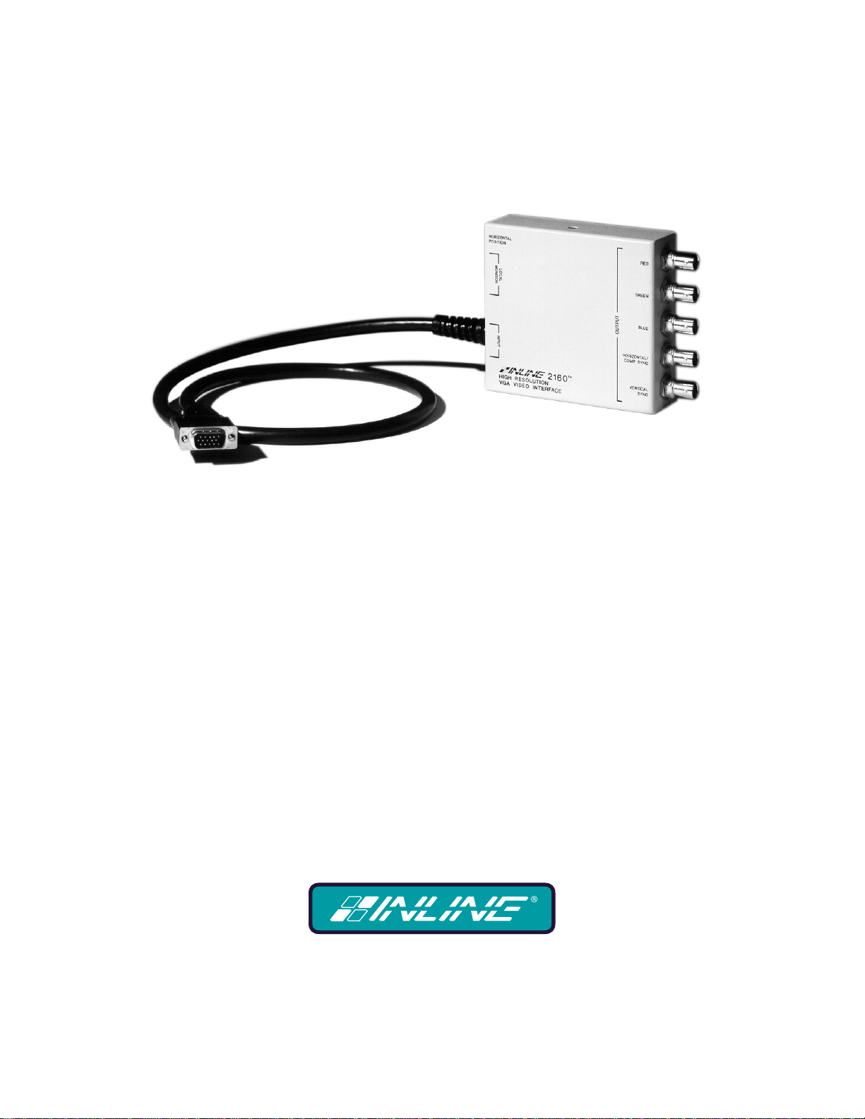
IN2160 High Resolution VGA Video Interface
Page 2
Installation and Safety Instructions
For Models without a Power Switch:
The socket outlet shall be installed near the equipment and shall be accessible.
For Models with 110 / 220V Power Selector:
Caution: Before applying power to this unit, the voltage selector must be set to the appropriate setting to match local A/C line
voltage. Improper setting of the voltage selector may cause damage to the unit and create a potential fire hazard.
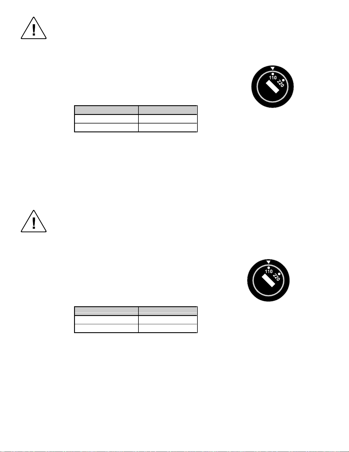
The voltage selector is a round switch located next to the A/C power input connector which looks
like this:
Using a straight slot screwdriver or small coin, rotate the selector to the correct position so that
the arrow lines up with 110 or 220 as appropriate for local power line voltage as indicated in the
chart below:
Local A/C Voltage Voltage Selector Setting
110 ~ 120 VAC 110
220 ~ 240 VAC 220
For all Models:
No serviceable parts inside the unit. Refer service to a qualified technician.
For Models with Internal or External Fuses:
For continued protection against fire hazard, replace only with same type and rating of fuse.
For IN2001 / IN3234 / IN3236 / IN3502 / IN3504 / IN3506 / IN3562 / IN3564 / IN3566 / IN3572 / IN3574 / IN3576:
Caution: Double pole / neutral fusing.
For all Models with Integral Lithium Battery:
Caution: Danger of explosion if battery is incorrectly replaced. Replace only with the same or equivalent type recommended by
the manufacturer. Dispose of used batteries according to the manufacturer’s instructions.
Instructions d’installation et de sécurité
Pour les modèles sans interrupteur de courant:
La prise de courant d’alimentation sera installé près de l’équipement et sera accessible.
Pour les modèles avec un sélecteur d’alimentation 110V/220V:
Attention: Avant de connecter l’appareil au circuit d’alimentation, le sélecteur de courant doit être positionné sur la sélection
appropriée correspondant au voltage du circuit de courant alternatif local. Une mauvaise sélection peut engendrer des
dommages à l’appareil et créer un danger d’incendie.
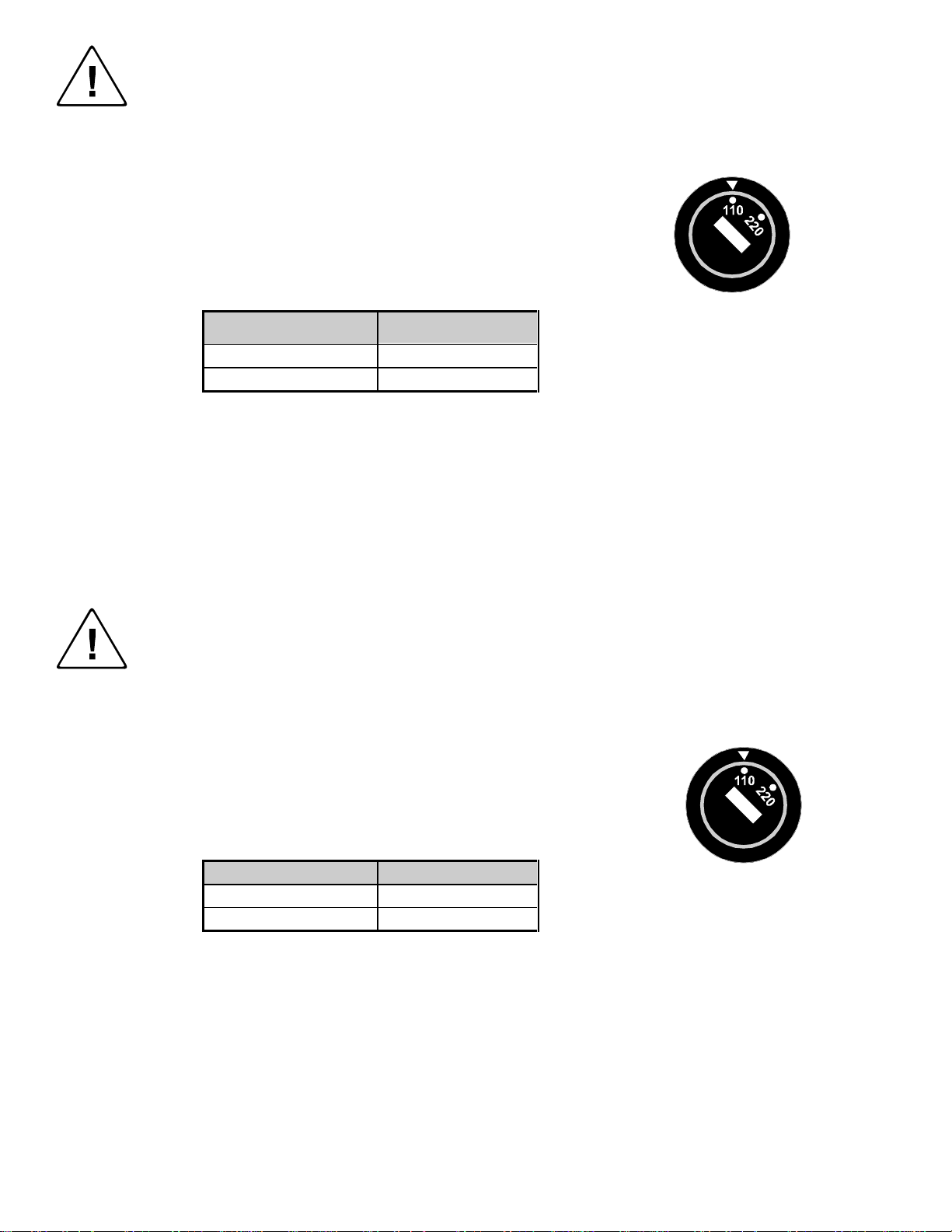
Le sélecteur d’alimentation est un commutateur rond positionné près du connecteur
d’alimentation. Il se représente comme suit:
A l’aide d’un tourne-vis plat ou d’une pièce de monnaie, le sélecteur peut être tourné dans la
position adéquate en veillaut que la flèche corresponde avec 110 ou 220, en fonction de la
valeur du circuit de courant local. (Voir tableau ci-dessous)
Circuit local AC Position Sélecteur
110 ~ 120 VAC 110
220 ~ 240 VAC 220
Pour tout les modèles:
Pas de composants à entretenir à l’intérieur. Confiez toute réparation à un technicien qualifié.
Pour les modèles équipés de fusibles internes ou externes:
Afin d’éviter tout danger d’incendie, ne remplacer qu’avec le même type et la même valeur de fusible.
Pour IN2001 / IN3234 / IN3236 / IN3502 / IN3504 / IN3506 / IN3562 / IN3564 / IN3566 / IN3572 / IN3574 / IN3576:
Attention: Double pôle / fusible au neutre.
Pour tout les modèles avec une batterie au lithium interne:
Attention: Danger d’explosion si la batterie est incorrectement remplacée. Ne remplacez la batterie qu’avec le même modèle,
ou avec un modèle recommandé par le constructeur. Traitez les batteries usagées selon les instructions du fabricant, ou selon
les normes écologiques en viguer.
Page 3
Installations und Sicherheitshinweise
Für Geräte ohne Netzschalter:
Die Netzsteckdose soll in de Nähe des Gerätes installiert und frei zugänglich sein.
Für Geräte mit 110 / 220V Spannungswähler:
Achtung: Bevor Sie dem Gerät Spann ung zuführen, muß der Spannungswähler entsprechend der Spannung des lokalen
Wechselspannungsnetzes eingestellt werden. Die falsche Stellung des Spannungswählers
kann eine Beschädigung des Gerätes und möglicherweise ein Feuer verursachen.
Der Spannungswähler ist ein runder Schalter in der Nähe der Netzeingangsbuchse mit
folgendem Aussehen:
Drehen Sie den Wähler mit einem normalen Schraubenzieher oder einer kleinen Münze so, daß
der Pfeil auf die 110 oder 220 zeigt, entsprechend der Spannung Ihr es lokalen Netzes wie hier
angezeigt:
Lokale Netzwechselspannung Stellung des
110 ~ 120 V 110
220 ~ 240 V 220
Für alle Geräte:
Keine Wartung innerhalb des Gerätes notwendig. Reparaturen nur durch einen Fachmann!
Für Geräte mit interner oder externer Sicherung:
Für dauernden Schutz gegen Feuergefahr darf die Sicherung nur gegen eine andere gleichen Typs und gleicher Nennleistung
ausgewechselt werden.
Für IN2001 / IN3234 / IN3236 / IN3502 / IN3504 / IN3506 / IN3562 / IN3564 / IN3566 / IN3572 / IN3574 / IN3576:
Achtung: Allpolige Absicherung
Für alle Geräte mit eingebauter Lithium Batterie:
Achtung: Explosionsgefahr bei falschem Batterieeinsatz. Batterie nur erstzen durch den gleichen oder entsprechenden Typ
wie vom Hersteller empfohlen. Entsorgung verbrauchter Batterien nur nach den Anweisungen des Herstellers.
Spannungswählers
Instalacion E Instrucciones de Seguridad
Modelos Sin Interruptor:
La conexión debe ser instalada cerca del equipo y debe ser accesible.
Modelos con Selector de Voltaje de 110/220V:
Precaución: Antes de operar esta unidad, el selector de voltaje debe instalarse de forma que corresponda a la linea de voltaje
local. Instalación inadecuada del selector de voltaje puede causar daño a la unidad y originar un incendio.
El selector de voltaje es un cambia vía redondo localizado cerca de la conexión electrica, como se
ve en el dibujo:
Use un destornillador comun o una moneda pequeña, mueva el selector a la posición correcta, de
forma que las flechas indiquen 110 o 220 de acuerdo con el voltaje local, como esta indicado a
continuación.
Voltaje Local A/C Selector de Voltaje
110 ~ 120 VAC 110
220 ~ 240 VAC 220
Para Todos Los Modelos:
Dentro de la unidad , no hay partes para reparar. Llame un tecnico calificado.
Modelos con Fusibles Internos o Externos:
Para prevenir un incendio, reemplace solo con el mismo tipo de fusible.
Modelos IN2001 / IN3234 / IN3236 / IN3502 / IN3504 / IN3506 / IN3562 / IN3564 / IN3566 / IN3572 / IN3574 / IN3576:
Precaución: Double Polo / Fusible Neutral.
Modelos con Bateria de Lithiun Interna:
Precaución: Peligro de explosión si la batería es reemplacada incorrectamente. Reemplace solamente con la misma clase de
batería, o una equivalente recomendada por el fabricante. Deseche las baterías usadas de acuerdo con las instrucciones del
fabricante.
Page 4
TABLE OF CONTENTS
Description / Features....................................................................................................................1
Installation......................................................................................................................................2
Application Diagram...........................................................................................................2
Horizontal Position Control..........................................................................................................3
Dip Switch Settings ........................................................................................................................4
Factory Default Settings......................................................................................................4
Special Application: LCD Display Devices..................................................................................5
Troubleshooting..............................................................................................................................6
Specifications..................................................................................................................................7
Optional Accessories...........................................................................................................7
Warranty.........................................................................................................................................8
CE COMPLIANCE
All products exported to Europe by Inline, Inc. after January 1, 1997 have been tested
and found to comply with EU Council Directive 89/336/EEC. These devices conform to
the following standards:
EN50081-1 (1991), EN55022 (1987)
EN50082-1 (1992 and 1994), EN60950-92
Shielded interconnect cables must be employed with this equipment to ensure
compliance with the pertinent Electromagnetic Interference (EMI) and
Electromagnetic Compatibility (EMC) standards governing this device.
FCC COMPLIANCE
This device has been tested and found to comply with the limits for a Class A digital
device, pursuant to Part 15 of the FCC rules. These limits are designed to provide
against harmful interference when equipment is operated in a commercial environment.
This equipment generates, uses and can radiate radio frequency energy and, if not
installed and used in accordance with the instruction manual, may cause harmful
interference to radio communications. Operation of equipment in a residential area is
likely to cause harmful interference, in which case the user will be required to correct the
interference at their own expense.
Page 5

1
DESCRIPTION
The IN2160 is a high performance computer video interfaces dedicated for VGA, SVGA, and XGA,
graphic cards. Like other Inline interfaces, the IN2160 performs the following functions:
Signal Splitting - allows the simultaneous connection and viewing of both the computer’s local
monitor and a second output device such as a large screen data projector, monitor, or color
printer.
Physical Interfacing - Computers employ many different types of video output connectors,
making it difficult to hook up computers directly to data projection devices. The IN2160
simplify interfacing, routing, and switching tasks by acting as an adapter. The IN2160 can be
attached to a VGA computers and will provide a video output signal on BNC connectors which
can easily be connected to an RGB display device. The output signal format may be set to any of
the following formats: RGBHV (default), RGBS, and RGsB.
The IN2160 is not
device must be compatible with the horizontal scan rate output by the computer video
card.
The IN2160 High Performance Dedicated VGA interface offers easy operation and the following
features:
♦ 400 MHz Bandwidth - High performance interface design ensures that video signals will be
interfaced with no loss of image detail.
♦ Analog Interface - the unit will operate with Analog Video with TTL level horizontal and vertical
sync signals.
♦ VGA Input and Output - the input and output are directly compatible with VGA, SVGA and XGA
graphic cards.
♦ Buffered Local Monitor Output - provides a buffered output to be connected to the local computer
monitor.
♦ Monitor Emulation Switch - eliminates the need for a termination plug if a local monitor is not
used. Emulates a color VGA monitor.
♦ Flexible Output Signal Formats - RGBHV (default), RGBS, and RGsB
♦ Horizontal Position Control - allows picture to be centered precisely on the data display screen.
♦ Sync Polarity Preservation Switch- enables the sync polarity to be preserved, or to set them for
negative polarity.
♦ Serration Pulse Removal Switch - for RGBS output, enables the user to remove serration pulses
from the sync output.
a scan converter. The data projector, monitor, or other output
©1996, 1997 - INLINE, INC. IN2160 OP E RA T ION MANUAL - VERSION 1.1 09/05/00
Page 6

2
INSTALLATION
This section offers step-by-step instructions for installing the IN2160. See the diagram below.
1. Turn the computer and computer monitor off. Disconnect the computer monitor (if present) from the
video output port on the computer.
2. Connect the input cable of the IN2160 to the output of the computer.
3. Connect the local computer monitor (if present) to the local monitor output of the IN2160. If no
local monitor is used, set the monitor emulation dip switch to emulate a color VGA monitor.
4. Connect the IN2160 output (5 BNC connectors) to the data display device’s RGB input, using three,
four, or five high resolution BNC cables or a multi-conductor RGBHV, RGBS, or RGB "snake". The
IN7000 Series, IN7100 Series and IN7200 Series high resolution cables are well suited for this
purpose. Take care while making connections to insure that the red output is connected to the red
input, green output to the green input, etc.
5. Set the dip switches for the requirements of your installation. The IN2160 factory default output
format is RGBHV. If your display device, routing system, or cabling require a different format, use
the dip switches to change the output signal to RGBS or RGsB as desire.
IN2160 OPERATION MANUAL VERS I ON 1.1 09/05/00 ©1996, 1997 - INLINE, INC.
Page 7

3
6. Connect the 9 VDC, 500 mA power adapter to the IN2160. The LED next to the power jack should
light to indicate it is on.
7. Complete the installation by turning the computer and computer monitor on. If required, adjust the
horizontal position control.
HORIZONTAL POSITION CONTROL
The location of the horizontal position control is diagrammed below. The horizontal position control
adjusts the position of the image on the data display device from left to right (it has no effect on the local
computer monitor).
Many data projectors and monitors have their own horizontal position control, and the interaction of the
display device’s horizontal control and the interface’s horizontal control may result in a dark image on the
data display. The following procedure is suggested to ensure best results:
1. Adjust the IN2160 horizontal position control so a good quality image is displayed. This control
should not be set to an extreme position.
2. Adjust the display device horizontal position control until the image is centered as desired.
3. If the image appears dark or the colors are not properly displayed, fine tune the controls on both the
display device and
the interface until the picture is centered and a good quality image is attained.
©1996, 1997 - INLINE, INC. IN2160 OP E RA T ION MANUAL - VERSION 1.1 09/05/00
Page 8

4
DIP SWITCH SETTINGS
Most installations will not require any changes to the dip switch settings, and the IN2160 will generally
be operated with the factory default settings. The Factory Default setting and specialized dip switch
settings are indicated below.
Factory Default Settings
Dip Switches ON: 2 & 4
Signal Format: Red / Green / Blue / Horizontal and Vertical Sync
Horizontal Position Control: Enabled
H & V Sync Polarity: Negative, Negative
Monitor Emulation: Disabled
With the exception of Dip Switch 6, all Dip Switches only affect the BNC output signal. They do not
affect the local monitor output.
Dip Switch 1 - Horizontal Position Control:
1 When enabled, the Horizontal Position control can be used to center the image of the
BNC output.
0 The Horizontal Position control is disabled. The output sync timing (position, pulse
width, etc.) is very similar to the input sync signal.
Dip Switch 2 - Sync on Green Output:
1 No sync on green. The output sync will be determined by dip switch 3.
0 The output will be RGsB (Sync on Green video.)
Dip Switch 3 - RGBS/RGBHV Output:
Dip switch 2 must be set to 1 for this dip switch to affect the output sync format.
1 RGBS output.
0 RGBHV output.
Dip Switch 4 - Horizontal and Vertical Sync Polarity:
This function is only valid when the IN2160 is set for RGBHV output (Dip switch 2 must be set to 1 and
dip switch 3 to 0.)
1 The Horizontal and Vertical sync signals will have a negative polarity regardless of the
polarity of the input signal.
0 The polarity of the Horizontal and Vertical sync signals will mirror the polarity of the
input signal.
Dip Switch 5 - Serration Pulse Removal:
This function is only valid when the IN2160 is set for an RGBS output.
1 The output composite sync signal will not have serration pulses.
0 The output composite sync signal will pass serration pulses.
Dip Switch 6 - Monitor Emulation:
This switch can be used to emulate a local monitor is one is not present (such as in the case of a laptop.)
The IN2160 automatically provides 75 Ohm termination for the video, and this switch provides an ID bit
identification to emulate a color VGA monitor.
1 Emulate the presence of a monitor.
0 Do not emulate a monitor. There must be a monitor to ensure a proper output from the
computer.
IN2160 OPERATION MANUAL VERS I ON 1.1 09/05/00 ©1996, 1997 - INLINE, INC.
Page 9

5
SPECIAL APPLICATION: LCD DISPLAY DEVICES
When using an Interface with an LCD panel or projector, some special considerations must be made.
Many LCD display devices utilize a “look-up table” when identifying an input signal. The display device
compares the parameters of the input signal to those in its table and looks for a match. If there is no
match to the signal format it is receiving, it may not be able to display the image properly. Some
parameters that the LCD devices use to recognize a signal are sync format, polarity, and horizontal and
vertical scan rates.
An Interface is often used to change the sync format. However, in doing this, you might make the signal
unrecognizable to the LCD device. For example, let’s look at a 640 x 480 VGA signal:
The user is utilizing the IN2160 interface to convert a VGA signal to an RGBS output. The LCD
projector is expecting to see VGA as RGBHV at 31.5 KHz. Because the interface changes the signal
format to RGBS, the LCD projector does not recognize the signal as VGA at 640 x 480 resolution. The
resulting image may be the wrong size, scrambled, or nothing at all.
The solution is to set the IN2160 for an RGBHV output so that the LCD projector can recognize it as
VGA. In addition, you may need to set the dip switches to mirror the input sync polarities and/or disable
the Horizontal position control.
©1996, 1997 - INLINE, INC. IN2160 OP E RA T ION MANUAL - VERSION 1.1 09/05/00
Page 10

6
TROUBLESHOOTING
The display device connected to the IN2160 output has a bad/scrambled image.
Solution 1: Verify that the correct input cable is being used.
Solution 2: The display device connected to the output of the interface may not be compatible with the
computer output. VGA runs at 31.5 KHz, but SVGA can be as high as 48 - 58 KHz with
newer modes such as 1600 x 1200 running at 80+ KHz!.
Solution 3: Check the dip switch settings to make sure the unit is putting out a sync format that the
display device can use. For most applications the default dip switch settings (see Page 5)
will work best.
Solution 4: The RGBS or RGBHV cable may have a bad sync line. Try running the sync through
another cable.
The output image is very dark.
Solution: The horizontal position control may be set off to an extreme position or may be interacting
poorly with the horizontal position control on the display device. Follow the horizontal
position adjustment procedure listed on Page 4.
The output image is missing a color.
Solution: Possibly the output RGBS or RGBHV cable is bad. Try switching connections on the output
to verify that the bad color’s cable is OK (Example: If there is no red, try running the green
output through the red cable and see if green is displayed or not.)
The output image is very bright and overdriven looking with poor contrast.
Solution 1: The signal may be unterminated. Check the internal termination jumpers to ensure they are
set for 75 Ohm termination.
Solution 2: Check the contrast and brightness settings on the display device. Many CRT type display
devices look best with the contrast set toward the upper end of the adjustment range (75 95%) and the brightness set towards the middle of the adjustment range (40 - 60%).
The output image is too green.
Solution 1: The dip switches may be set for Sync on Green output. Try changing the dip switches to
output an RGBS or RGBHV signal.
The output image is doubled, with two images displayed side-by-side.
Solution: The display device may not be compatible with the horizontal scan rate of the computer.
This problem often occurs when a 31.5 KHz VGA signal is sent into an RGB monitor which
is only compatible with signals at 15.75 KHz.
If problems persist, call INLINE Technical Services at (800) 882-7117 for further assistance.
IN2160 OPERATION MANUAL VERS I ON 1.1 09/05/00 ©1996, 1997 - INLINE, INC.
Page 11

7
SPECIFICATIONS
Input
Connector type
RGB Video Signals
Input Impedance
Sync Signals
Horizontal Scan Range
Vertical Scan Range
Output
Connector Type
Output Signal Formats
RGB Signals
Bandwidth
Rise and Fall Times
Gain
Sync Signal
Horizontal Pulse Width
Vertical Pulse Width
Controls
External
Internal
Dimensions
Size
Shipping Weight
Power
Power Supply
Regulatory Compliance
Safety
EMI
Optional Accessories
IN8000 Series VGA Cable: Available in a variety of lengths from 3’ to 100’
IN7000-5 Series RGBHV Cable: Standard 5 - BNC Cable available in a variety of lengths from 6' to 250'
IN7100-5 Series RGBHV Cable: High Resolution 5 - BNC Cable, available in lengths from 6' to 250'
IN7200-5 Series RGBHV Cable: Ultra High Resolution 5 - BNC Cable, available in lengths from 6' to 250'
15 Pin HD male
Analog, 0.7 Vp-p Nominal
75 Ohms
TTL compatible
15.0 KHz - 135.0 KHz
30 Hz - 180 Hz
5 BNC Female connectors
RGBHV (Default), RGBS or RGsB,
Analog Video, 75 ohm impedance
400 MHz @ -3 dB
0.875 nano seconds
1.0 ± 5%
H, V and S: 5V unterminated and 2Vp-p 75 ohm terminated
Gs: 0.3 Vp-p 75 Ohm terminated
Horizontal Position Enabled: approximately 1.5 µsec
Horizontal Position Disabled: Approximately the same
as the input signal
Approximately the same as the input signal
Horizontal Position Control
Dip Switches
Untermination jumpers for red, green and blue
1.25" H x 5" W x 4" D
3 lb.
IN9204-X: External AC to DC Power Transformer, 9V 500 mA
UL 1950, 3rd Ed.; CE: EN60950-92;
CAN/CSA-22.2 No. 950 3
FCC class A; CE: EN50081-1,
EN55022, EN50082-1
rd
Ed.
©1996, 1997 - INLINE, INC. IN2160 OP E RA T ION MANUAL - VERSION 1.1 09/05/00
Page 12

8
WARRANTY
♦
INLINE warrants the equipment it manufactures to be free from defects in materials and
workmanship.
♦
If equipment fails because of such defects and INLINE is notified within two (2) years from the
date of shipment, INLINE will, at its option, repair or replace the equipment at its plant,
provided that the equipment has not been subjected to mechanical, electrical, or other abuse or
modifications.
♦
Equipment that fails under conditions other than those covered will be repaired at the current
price of parts and labor in effect at the time of repair. Such repairs are warranted for ninety (90)
days from the day of re-shipment to the Buyer.
♦
This warranty is in lieu of all other warranties expressed or implied, including without
limitation, any implied warranty or merchantibility or fitness for any particular purpose,
all of which are expressly disclaimed.
The information in this manu al has been carefully checked and is believed to be accurate. However,
Inline, Inc. assumes no responsibility for any inaccuracies that may be contained in this manual. In no event will
Inline, Inc. be liable for direct, indirect, special, incidental, or consequential damages resulting from any defect
or omission in this manual, even if advised of the possibility of such damages. The technical information
contained herein regarding IN2160 features and specifications is subject to change without notice.
IBM is a registered trademark of International Business Machines. Apple, MAC, Quadra and Centris, are
registered trademarks of Apple Computers, Inc. Iris Indigo is a registered trademark of Silicon Graphics. Sun
Sparc Station is a registered trademark of Sun Microsystems, Inc. All other trademarks and registered
trademarks are the property of their respecti ve co mpanies.
© Copyright 1996, 1997 Inline, Inc. All Rights Reserved
INLINE, INC. ♦ 810 West Taft ♦ Orange, CA 92865
800-882-7117 ♦ 714-450-1800 ♦ FAX 714-450-1850 ♦ www.inlineinc.com
©1996, 1997 - INLINE, INC. IN2160 OP E RA T ION MANUAL - VERSION 1.1 09/05/00
 Loading...