

Page 1
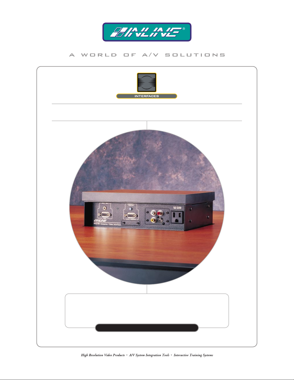
ELEVATING TABLE MOUNTABLE INSTALLATION INTERFACE
WITH MODULAR A / V CONNECTOR FACEPLATES
IN2118
IN2118
OPER AT ION MANUAL
Page 2
Installation and Safety Instructions
For Models without a Power Switch:
The socket outlet shall be installed near the equipment and shall be accessible.
For all Models:
No serviceable parts inside the unit. Refer service to a qualified technician.
For Models with Internal or External Fuses:
For continued protection against fire hazard, replace only with same type and rating of fuse.
Instructions d’installation et de sécurité
Pour les modèles sans interrupteur de courant:
La prise de courant d’alimentation sera installé près de l’équipement et sera accessible.
Pour tout les modèles:
Pas de composants à entretenir à l’intérieur. Confiez toute réparation à un technicien qualifié.
Pour les modèles équipés de fusibles internes ou externes:
Afin d’éviter tout danger d’incendie, ne remplacer qu’avec le même type et la même valeur de fusible.
Installations- und Sicherheitshinweise
Für Geräte ohne Netzschalter:
Die Netzsteckdose soll in der Nähe des Gerätes installiert und frei zugänglich sein.
Für alle Geräte:
Keine Wartung innerhalb des Gerätes notwendig. Reparaturen nur durch einen Fachmann!
Für Geräte mit interner oder externer Sicherung:
Für dauernden Schutz gegen Feuergefahr darf die Sicherung nur gegen eine andere gleichen Typs und gleicher Nennleistung
ausgewechselt werden.
Instalacion E Instrucciones de Seguridad
Modelos Sin Interruptor:
Para Todos Los Modelos:
Modelos con Fusibles Internos o Externos:
La conexión debe ser instalada cerca del equipo y debe ser accesible.
Dentro de la unidad , no hay partes para reparar. Llame un tecnico calificado.
Para prevenir un incendio, reemplace solo con el mismo tipo de fusible.
CE COMPLIANCE
All products exported to Europe by Inline, Inc. after January 1, 1997 have been tested and found to
comply with EU Council Directive 89/336/EEC. These devices conform to the following
standards:
EN50081-1 (1991), EN55022 (1987)
EN50082-1 (1992 and 1994), EN60950-92
Shielded interconnect cables must be employed with this equipment to ensure compliance with
the pertinent Electromagnetic Interference (EMI) and Electromagnetic Compatibility (EMC)
standards governing this device.
FCC COMPLIANCE
This device has been tested and found to comply with the limits for a Class A digital device,
pursuant to Part 15 of the FCC rules. These limits are designed to provide against harmful
interference when equipment is operated in a commercial environment. This equipment generates,
uses and can radiate radio frequency energy and, if not installed and used in accordance with th e
instruction manual, may cause harmful interference to radio communications. Operation of
equipment in a residential area is likely to cause harmful interference, in which case the user will be
required to correct the interference at their own expense.
Page 3

Table of Contents
Product Overview................................................................................................2
Description........................................................................................................ 2
Eighteen Models Available...............................................................................2
Compatibility........................................................................................................3
Input..................................................................................................................3
Output............................................................................................................... 3
Installation............................................................................................................ 4
Mounting the Interface......................................................................................4
IN2118 Installation Diagram: Table Cutout.....................................................5
Adjusting the IN2118....................................................................................... 7
IN2118 Installation Diagram: Adjustments......................................................8
Maximum Bearing Load................................................................................... 9
Connecting the Interface................................................................................... 9
Adapter / Extension Cables for Input and Local Monitor Output...................11
IN2118 Installation Diagram: (Bottom) Connectors and Controls.................12
IN2118 Application Diagram......................................................................... 13
IN2118 Installation Diagram: (Faceplates) Connectors and Controls............ 14
Operation............................................................................................................ 15
Horizontal Position Control............................................................................15
Dipswitch Settings.......................................................................................... 15
Optimal Settings for LCD / DMD / D-ILA / Plasma Displays.......................16
Remote Control Operation.............................................................................. 16
Contact Closure Devices.................................................................................16
A/V Connector Modules.................................................................................17
Specifications......................................................................................................19
Troubleshooting (IN2118-A, D & G)................................................................20
IN2118 Dimensions Diagrams...........................................................................22
Warranty............................................................................................................25
Page 4
2
Product Overview
DESCRIPTION
The IN2118 is a high performance computer video interface for analog video signals including
VGA, SVGA, XGA, SXGA, UXGA, Macintosh
workstations. The IN2118 flush mounts neatly in a conference room / boardroom table or other
presentation furniture. The IN2118 is a two-sided unit that provides easy access to a highresolution computer video interface, a modular A/V connector faceplate and / or one or two A/C
convenience outlets on either side of the table.
Disappearing Flush Mount Design - When the unit is in the lowered position, it sits
completely flush with the table surface.
Motorized Unit - can be raised and lowered by pressing down on the top surface, or via
contact closure control.
Safety Features - stop the interface from descending if it senses an obstruction such as
attached cables or wayward fingers.
Installation Flexibility - The IN2118 includes several adjustments to help installers
position the unit precisely in a conference table / presentation furniture.
Front Panel A/C Convenience Outlets - are provided to power a laptop computer or
other A/V equipment that will be located on the table.
Modular A/V Connector Plate - The IN2118 simplifies the design and installation pro-
cess since a single unit fills the function of both video interface and A/V connector plate.
Flush mounted in the table and rising into place when needed, the IN2118 provides easy access
for making computer and A/V connections, reducing equipment clutter, and complements the
décor of high tech control rooms, civic / legislative chambers and courtroom installations.
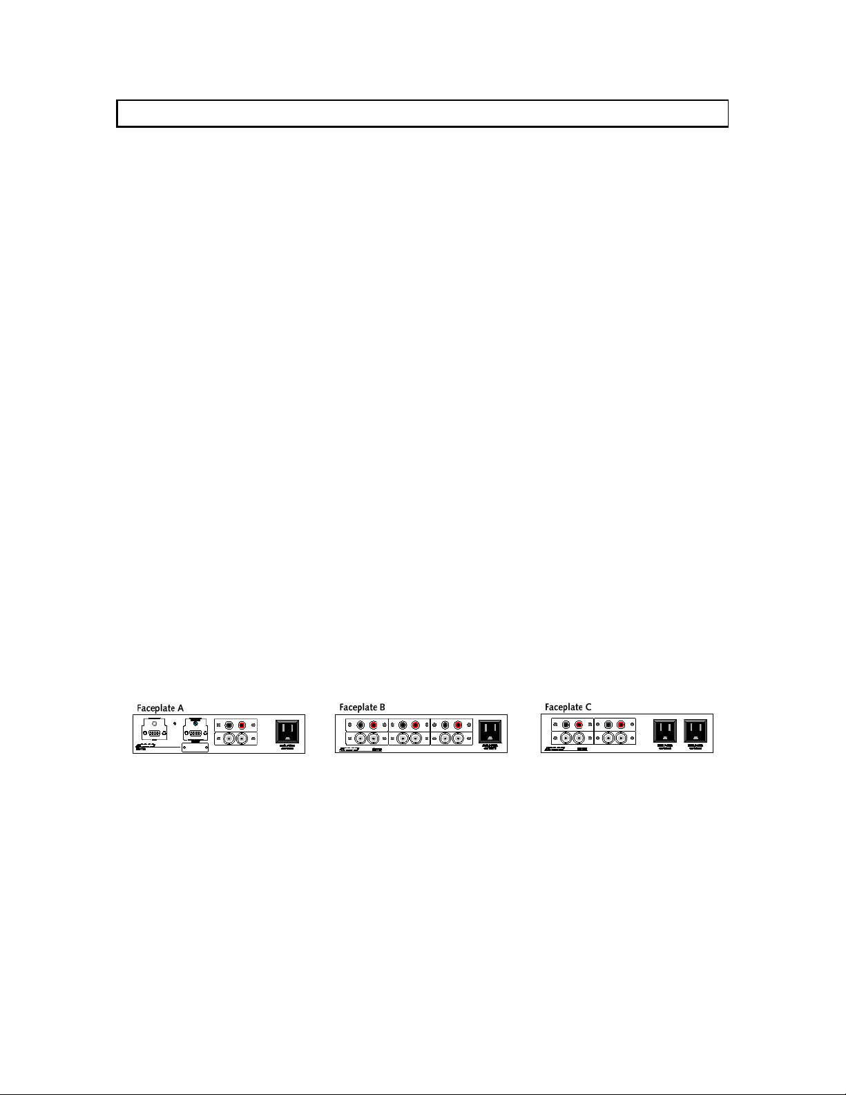
EIGHTEEN MODELS AVAILABLE
The IN2118 is available in several different combinations to match the computer video interface,
A/V connector and A/C power outlet requirements of each installation.
®
, SunTM, SGI
TM
and other high-resolution
Faceplate A: 400 MHz Interface, holds (2) A/V Connector Modules & (1) Edison A/C Outlet
Faceplate D: 400 MHz Interface, holds (2) A/V Connector Modules & (1) IEC A/C Outlet
Faceplate G: 400 MHz Interface, holds (2) A/V Connector Modules & (1) Europlug A/C Outlet
Faceplate B: Holds (6) A/V Connector Modules & (1) Edison A/C Outlet
Faceplate E: Holds (6) A/V Connector Modules & (1) IEC A/C Outlet
Faceplate H: Holds (6) A/V Connector Modules & (1) Europlug A/C Outlet
Faceplate C: Holds (4) A/V Connector Modules & (2) Edison A/C Outlets
Faceplate F: Holds (4) A/V Connector Modules & (2) IEC A/C Outlets
Faceplate K: Holds (4) A/V Connector Modules & (2) Europlug A/C Outlets
Each unit can be ordered with any combination of two (2) faceplates. Complete descriptions of all
available models can be found on pages 26 & 27 of the INLINE 2001 Product Catalog.
Note: A/V Connector Modules are not included and must be ordered separately (see page 17).
IN2118 Operation Manual - Preliminary 01/31/01 ©2001 - Inline, Inc.
Page 5
3
The IN2118 Interface is not a scan converter. The data projector, monitor
or other output device must be compatible with the horizontal scan rate,
vertical scan rate and resolution output by the computer video card.
Compatibility
INPUT
The IN2118 Interface will accept high-resolution video signals from virtually any computer that
outputs an analog video signal. The unit will work with signals at virtually any resolution and
refresh rate. Compatible computer video signals include VGA, SVGA, XGA, MAC, SUN, SGI
and other high-resolution computers outputting an analog video signal. Input signal compatibility
parameters are listed below.
Video Signal: Analog RGB Video
Signal Format: RGBHV, RGBS, RGsB*
Horizontal Frequency Range: 30 KHz to 130 KHz
Vertical Refresh Rates: 30 Hz to 120 Hz
* The IN2118 Interface will operate with RGsB input signals. However,
the unit will not strip sync off of the green. RGsB input signals are always
output as RGsB (they cannot be output as RGBS or RGBHV). Also, the
horizontal position control will not operate when used with RGsB input
signals.
OUTPUT
The output signal of the IN2118 Interface is analog RGB video with TTL sync on 3, 4 or 5
female BNC connectors. The output format can be set to RGBHV, RGBS or RGsB using
dipswitches. This output signal is compatible with high-resolution data grade monitors and data /
graphics projectors.
VGA, MAC, SUN, SGI and other high-resolution workstations operate in
several video modes encompassing a wide range of resolutions and scan
rates. Many of the video signals from the newest models can run as high
as 70 KHz or more, with the newest VGA cards offering an output resolution of 1600 x 1200 (some can even go as high as 1000 x 1080). The data
projector or monitor connected to the interface output must be compatible
with the horizontal scan rate and vertical refresh rate of the computer’s
video signal. Check the documentation for both the computer graphics
card and the data display device to ensure compatibility.
©2001 - Inline, Inc . IN2118 Operation Manual - Preliminary 01/31/01
Page 6
4
Installation
MOUNTING THE INTERFACE
WARNING: The IN2118 should only be mounted by licensed and bonded installers. Care
must be taken to avoid scarring or damaging presentation / conference room furniture.
Before installing the IN2118, refer to the Dimensions Diagrams on pages
22 - 24 and make sure the table / installation furniture will accommodate
all
the dimensions of the unit.
In the following example, the IN2118 is installed in a conference room table with a laminated
surface. Depending on the installation, your emplacement may require specialized tools,
additional materials, safety equipment, etc.
Hint: To simplify your installation, make the lid fit the hole
NECESSARY TOOLS & SUPPLIES:
Power Tools: Hand Tools: Miscellaneous:
Drill
Router
Saw (Circular or Saber)
IN9185 Template
Carpenter’s Level
(2) C-Clamps
Wood File
Phillips Screwdriver
1. Locate the desired mounting location on the tabletop / installation furniture surface and
mark the center with a pencil.
2. Attach the extension arms to the optional IN9185 Table Routing Template and position it
around the center mark. Make sure that the 12 flat head screws are countersunk below
the surface of the extension arms. Failure to do so may scar the furniture.
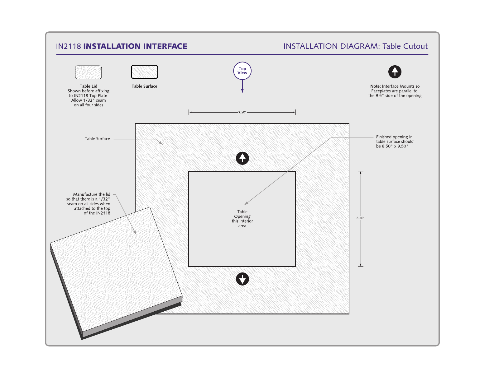
3. Once the Template has been situated properly, use a pair of C-Clamps to secure the
extension arms to the edges of the table. Use a pencil to outline the 9 ½” x 8 ½” inside
edge of the template (see the Installation Diagram on the following page).
Hint: Marking the inside edge of the IN9185 will alert the installer of any accidental
template movement that may occur while routing the hole.
4. Using a router, carefully cut the opening in the table surface (very thick table surfaces
may require additional routing). Use a file to square the round edges. Remove the
template when finished.
When using the IN9185, installers must
(collar) that provides ¼” clearance from the inside edge of the template.
, not vice versa.
Adhesive
Double sided tape
Wood Screws and
Washers
1/32” Feeler Gauge
(Optional)
use a router bit template guide
IN2118 Operation Manual - Preliminary 01/31/01 ©2001 - Inline, Inc.
Page 7
5
©2001 - Inline, Inc . IN2118 Operation Manual - Preliminary 01/31/01
Page 8
6
5. Most installations will require fabrication of a new cover surface (lid). Using the IN9185
template, make another outline on a matching piece of material. Cut out the new lid
using a power / saber saw.
Note: Bear in main that the new surface must accommodate a 1/32” gap on all four sides
between the lid and the table opening.
6. Finish the top and sides of the lid, and the sides of the opening in the table. Again, there
should be a 1/32” seam around all four edges of the lid when it sits flush with the table
surface.
Note: If matching lamina is unavailable, installers may have to completely resurface the
table / presentation furniture, or consider other installation options.
Installers may wish to use 1/32” feeler gauges to achieve precise
equidistant spacing on all four sides of the lid. Hint: A standard size
paper clip (one and one quarter inches long) is almost 1/32” in diameter.
7. The IN2118 is secured to a plate base to prevent damage during shipment. Disconnect
the four screws and remove the plate.
Note: The IN2118 is delivered with the top plate in the lowered position. Do not
raise the
plate until the installation is complete.
8. Loosen the four (4) upper wing nuts and disconnect the mounting flange from the main
housing (see the Adjustments Diagram on page 8).
9. Working from the underside of the table, position the mounting flange so that the gap
between the inside edges of the flange and the table’s opening are roughly equidistant (a
precise adjustment will be done later). The flange contains eight (8) mounting holes: four
oversized primary holes on the corners and four smaller secondary holes on the sides.
The primary holes are used to position the unit, while the secondary holes are used to
permanently attach the IN2118 to the table / installation furniture. Mark the four (4)
primary
Note: Do not
holes only.
drill the secondary holes or permanently attach the flange until the unit has
been positioned properly!
10. Set the flange aside and carefully drill the primary holes. Care must be taken not to
penetrate the surface of the table. Drill the holes in the center of the oversized openings
to provide maximum centering flexibility.
11. Attach the flange to the underside of the table. Do not fully tighten the screws.
12. Attach the main housing to the mounting flange by securing the four (4) upper wing nuts.
Make sure that the top of the housing sits flush with all four sides of the flange before
tightening the nuts.
For applications in which a new table / presentation furniture will be fabricated and / or the IN2118 will be installed at a remote location, the main
housing should not be attached to the mounting flange during shipment.
IN2118 Operation Manual - Preliminary 01/31/01 ©2001 - Inline, Inc.
Page 9
7
ADJUSTING THE IN2118
This section offers step-by-step instructions for precisely situating the IN2118 in the table /
presentation furniture. An Adjustment Diagram is provided on the following page.
Do not permanently attach the cover surface (lid) to the top plate until the
IN2118 has been fully installed in the table / presentation furniture.
1. Center the IN2118 until a roughly equidistant gap is achieved between all four sides of the
top plate and the table’s opening (once again, a precise adjustment will be done later).
Once the unit has been properly positioned in the table, tighten the four (4) primary screws.
2. Loosen the upper wing nuts and disconnect the main housing. Carefully drill the (4)
secondary holes and secure the mounting flange to the table. Once again, care must be
taken not to penetrate the surface of the table.
3. Reattach the main housing to the mounting flange. Using the IN9230 IEC Power Cable
(included), apply power to the IN2118, turn it on, and press down on the top plate surface
to raise the unit.
4. With the IN2118 in the raised position, place a Carpenter’s Level across the top of the
plate and level the unit by adjusting the upper wing nuts. When the unit has been
centered, turn the Level 45º and adjust again. This step may have to be repeated several
times until a true level surface is achieved.
Note: Leveling the unit while in the raised position will ensure that the top plate and the table
surface remain parallel (when the IN2118 is in the raised position), and sits flush when the unit
is fully descended.
5. Before adjusting the height of the interface, use two-sided tape to temporarily attach the
cover surface material (lid) to the top plate.
6. To adjust the height of the IN2118, press down on the lid and lower the unit. Loosen the
four (4) lower wing nuts. Position the lid so that it sits completely flush with the table
surface and tighten the wing nuts. Raise and lower the interface to ensure that the unit
achieves sufficient clearance when raised, and sits flush when lowered. The IN2118
should ascend and descend smoothly.
The lower wing nuts allow installers to adjust for varying tabletop thickness
(up to two inches) and provide a precise flush-mount installation
7. Using a strong adhesive, permanently attach the lid to the top plate.
©2001 - Inline, Inc . IN2118 Operation Manual - Preliminary 01/31/01
Page 10

120/230VAC; 10A: 60/50HZ
8
IN2118 Operation Manual - Preliminary 02/05/01 ©2001 - Inline, Inc.
Page 11

9
MAXIMUM BEARING LOAD
In applications where the unit will be raised and lowered by hand or through the contact closure
control port, the maximum weight of the cover surface material affixed to the top of the interface
(the lid) should not exceed 10 pounds / 4.5 kilograms.
The maximum load bearing on the motor is 30 pounds, but exceeding the
10 pound / 4.5 kilogram load limit will shorten the life of the motor and
may compress the activation spring, preventing the unit from operating
properly..
CONNECTING THE INTERFACE
This section offers step-by-step instructions for connecting the IN2118 Interface. A Connectors
and Controls Diagram is included on page 12, and an Application Diagram is on page 13.
CAUTION: Installation of the IN2118 Interface must only be carried out by qualified technicians. Before making any connections, make sure that there is no power connected to the unit.
1. Run the video coax cable(s), power cable, remote cable, and optional accessory cables
(audio / video / phone / data / control cables) to the interface.
Warning: All internal cables and connectors are pre-terminated at the
factory. Removing the connector plate may damage internal components
and will void all warranties. If you have any questions, please call INLINE
technical support at (714) 921-4100.
2. Terminate any Audio, Video and Control Cables to the backside of the A/V Connector
Modules as required by your installation (a complete list of available modules is provided
on pages 17 & 18).
Note: The IN2118 provides a Flexible Cable Conduit to ensure that the accessory cables are
not pinched or damaged while the unit ascends / descends. Before making any terminations,
run all the accessory cables through the bottom of the conduit to the A/V connector plate
opening(s).
3. Using the IN9334 3/32” Allen Wrench (included) - attach the modular connector(s) to
the IN2118 faceplate, making sure that none of the cables are pinched or damaged
(faceplate diagrams are provided on page 14). Once the connectors are securely installed,
tighten the Cable Strain Relief Clamps.
Note: All optional A/C convenience outlet(s) are pre-terminated at the factory.
4. Connect the Video Coax Cable to the (5) BNC female connectors using three, four, or
five high-resolution BNC cables, or a multi-conductor RGBHV, RGBS or RGB "snake.”
The IN7000 / IN7200 / IN7300 and IN7400P Series high-resolution cables are well suited
for this purpose. Take care while making connections to insure that the red output is
connected to the red input, green output to the green input, etc. For dual interface
applications, a second set of BNC connectors is provided.
©2001 - Inline, Inc . IN2118 Operation Manual - Preliminary 01/31/01
Page 12

10
5LJKW*URXQG
5. Connect the Left, Right and Ground Conductors on the audio cables to the 5-pin
captive screw terminal. This connector will accept stranded or solid cables from 20 - 26
AWG. The IN2118 Interface takes an unbalanced stereo audio input, buffers the signal
and outputs it as balanced stereo audio. This is desirable for systems where the audio
signal will be connected to equipment with balanced audio inputs, and is helpful in
preserving signal integrity and minimizing outside signal interference (which often occurs
while sending the audio signal over lengthy cable runs).
5LJKW
5LJKW
/HIW
/HIW*URXQG
/HIW
6. Access the Dipswitches by removing the screws on the front plate (the IN9334 3/32”
Allen Wrench is included). Use the IN9339 Adjustment Tool to set the switches as
appropriate for your installation (a complete description of the dipswitch settings is
provided on page 15). The factory default output format is RGBS / RGBHV. If your
display device, routing system or cabling requires a different format, use the dipswitches
to change the output signal to RGsB. Replace the front plate and tighten the hex screws.
7. Connect the Remote Device to the 4-pin captive screw terminal (see the Remote Control
Operation Section on page 16).
8. Apply Power to the IN2118 using the IN9230 IEC (USA only) power cable (included).
9. Complete the Installation by turning the interface ON (the power switch is located to the
right of the A/C connector). The front panel LED (on the Interface) will illuminate.
FOR IN2118-A, D & G INSTALLATIONS:
10. Connect the Computer Graphics Card to the IN2118 15-pin video input port (a
Connectors and Controls Diagram is provided on page 14).
• PC / MAC / SGI Computers with 15-pin HD Video Ports - can be connected via
IN8000M-1 / IN8200M-1 Series high-resolution coaxial VGA cables.
• Older Macintosh (15-pin D) / SUN (13W3) / Workstations (4 or 5 BNC) - can be
connected using the appropriate input / output cables listed in the chart on the following
page.
11. Connect the Computer Sound Card Output (if applicable) to the IN2118 3.5mm female
stereo audio input connector using an IN8200-1 Series cable (15-pin HD with 3.5mm stereo
mini male), or an IN9106 audio patch cable (3.5mm stereo mini male to 3.5mm stereo mini
male). For computers with RCA connectors, use the IN9107 audio adapter cable [(1) 3.5mm
stereo mini male to (2) RCA male].
IN2118 Operation Manual - Preliminary 01/31/01 ©2001 - Inline, Inc.
Page 13

11
12. Connect the Local Computer Monitor (if applicable) to the local monitor output port of
the IN2118. Monitors with 15-pin VGA connectors will attach directly to the interface.
For other types of monitors, refer to the table below.
If a local monitor is required, the monitor emulation dipswitch must be
disabled (see the Dipswitch Settings Section on page 15 for more details).
ADAPTER / EXTENSION CABLES FOR INPUT AND LOCAL MONITOR OUTPUT
The IN2118 Interface has 15-pin HD VGA-type input and local monitor output connector ports.
The following cables / adapters are available:
Computer 3’ 6’ 12’ 25’ 35’ +
VGA: 15-Pin HD
Input Cable (M-M)
Output Cable (M-F)
VGA with Stereo Audio: 15-Pin HD with 3.5mm (M-M) mini DIN
Input Cable (M-M)
Output Cable (M-F)
MAC with 15-Pin D:
Input Cable (M-M)
Output Cable (M-F)
MAC G3, G4 and PowerBook with 15-Pin HD*:
Input Cable (M-M)
Output Cable (M-F)
SUN: 13W3 (may also be used with SGI with RGsB output)
Input Cable (M-M)
Output Cable (M-F)
Workstation: 5 BNC / RGBHV
Input Cable (M-M)
Output Cable (M-M)
Workstation: 4 BNC / RGBS
Input Cable (M-F)
*Newer Mac G3 models (with translucent cases) have 15-Pin HD connectors (pins arranged in 3 rows).
Older G3 models (with solid white enclosures) incorporate 15-Pin D connectors (pins arranged in 2 rows).
IN8003M-1 IN8006M-1 IN8012M-1 IN8025M-1 IN80xxM-1
IN8006-1 IN8012-1 IN8025-1 IN80xx-1
IN8203M-1 IN8206M-1 IN8212M-1 IN8225M-1 IN82xxM-1
IN8203-1 IN8206-1 IN8212-1 IN8225-1 IN82xx-1
IN9140M IN9144M
IN9141 IN9145
IN8006M-1 IN8012M-1 IN8025M-1 IN80xxM-1
IN8006-1 IN8012-1 IN8025-1 IN80xx-1
IN9142M IN9146M
IN9143 IN9147
IN9045-L6 IN9045-L12 IN9045-L25 IN9045-Lxx
IN9045-L6 IN9045-L12 IN9045-L25 IN9045-Lxx
IN9100
©2001 - Inline, Inc . IN2118 Operation Manual - Preliminary 01/31/01
Page 14

12
IN2118 Operation Manual - Preliminary 01/31/01 ©2001 - Inline, Inc.
Page 15

13
©2001 - Inline, Inc . IN2118 Operation Manual - Preliminary 01/31/01
Page 16

14
IN2118 Operation Manual - Preliminary 01/31/01 ©2001 - Inline, Inc.
Page 17

15
Operation
HORIZONTAL POSITION CONTROL
The location of the horizontal position control is shown in the Faceplate A Connectors and
Controls Diagram on the previous page. This control adjusts the position of the image on the
data display device. The horizontal position control has no effect on the local computer monitor.
If the horizontal position adjustment is set to an extreme position on either the display device or
the IN2118 Interface, the output image may appear dark and / or the colors may be displayed
improperly. To position the video image and achieve optimum picture quality:
1. Set the display device’s horizontal position control to the center of its adjustment range.
2. Adjust the horizontal position control on the IN2118 Interface until the picture is
centered properly on the display device.
Note: The horizontal position control does not work with RGsB input signals.
DIPSWITCH SETTINGS
Most installations will not require any changes to the dipswitch settings. The factory default and
specialized dipswitch settings are indicated below.
Note: The switches are located under the Dipswitch access plate (see the diagram on the previous
page).
Factory Default Settings:
Dipswitches ON: 2 & 4
Signal Format: Red / Green / Blue / Horizontal and Vertical Sync
Horizontal Position Control: Enabled
H & V Sync Polarity: Negative, Negative
Monitor Emulation: Disabled
The following table lists the functions of the 6 dipswitches:
DIPSWITCH FUNCTION SETTING
*If monitor emulation is desired when using a MAC G3 (with 15-pin HD connector) or G4, dipswitch #6 must be set to 1.
1
2
3
4
5
6
Horizontal Position
RGsB Output (sync on green)
RGBS or RGBHV Output (dip
switch 2 must be set to 1)
RGBHV Output Sync Polarity
Serration Pulse Removal (for
RGBS or RGsB output)
Monitor Emulation (VGA color /
MAC* 640 x 480)
1 = Disabled
0 = Enabled
1 = RGBS or RGBHV
0 = RGsB
1 = RGBS
0 = RGBHV
1 = Negative, Negative
0 = Mirror Input Polarities
1 = Remove Serration Pulses
0 = Pass Serration Pulses
1 = Emulation Disabled
0 = Emulation Enabled
©2001 - Inline, Inc . IN2118 Operation Manual - Preliminary 01/31/01
Page 18

16
OPTIMAL SETTINGS FOR LCD / DLP / D-ILA / PLASMA DISPLAYS
The following output sync settings provide maximum signal preservation and are recommended
for the best image quality with LCD, DLP, D-ILA and Plasma Display devices. Depending on
the design of the display device’s sync processing circuitry, you may be able to set the horizontal
position control (dipswitch #1) to the enabled position. However, experimentation with your
display device is the best way to determine whether you can achieve a stable image with the
horizontal position enabled. Many LCD displays include a fine phase control, which can be
adjusted to optimize picture quality.
Dipswitches ON: 1 & 2
Signal Format: Red / Green / Blue / Horizontal and Vertical Sync
Horizontal Position Control: Disabled
H & V Sync Polarity: Mirror Input Polarities
REMOTE CONTROL OPERATION
The IN2118 can be raised and lowered by pressing down on the top surface, or via remote control.
The remote port is a 4-pin captive screw terminal on the connector plate that allows the interface to
be controlled by any device that is capable of providing a latching contact closure, or by an RS-232
control device (when used with an optional IN6901 / IN6902 RS-232 to contact closure converter).
Contact Closure Control: The interface can be raised or
lowered via the remote port by providing a latching contact
closure between pin 1 and pin 2 on the remote jack.
Opening / closing the contact closure causes the unit to
ascend / descend. The manual control (pressing down on the
top surface) and the contact closure switch work
independently. Therefore, an open or closed status between
pins 1 & 2 on the remote port could select either the raising
or lowering of the interface, depending on the current
position of the unit.
Status: The remote connector status pins (3 & 4) can be used to provide feedback to a control
system to indicate whether the IN2118 is in the raised or lowered position. The status pin will be
open or closed depending on the current position:
Closed: Unit is in the raised position
Open: Unit is in the lowered position
CONTACT CLOSURE DEVICES
Any device capable of providing a latching contact closure may be used to control the IN2118.
Several contact closure type devices are available:
IN6901 / IN6902 RS-232 to Contact Closure Converter - allows the IN2118 and other
INLINE devices with contact closure control ports to be regulated by RS-232 sources.
Control System - many control systems are capable of providing contact closures.
IN2118 Operation Manual - Preliminary 01/31/01 ©2001 - Inline, Inc.
Page 19

17
A/V CONNECTOR MODULES
Connector Module Black / White Description Type Size
Video Modules
IN9351B / IN9351W (2) BNC Female Barrel Single
IN9352B / IN9352W (1) 4-Pin Mini DIN Female (S-Video) Installation Single
IN9357B / IN9357W (2) F-Connector Female Barrel Single
IN9363B / IN9363W
(1) 4-Pi n Mini DIN Female (S-Video)
(1) BNC Female Barrel
IN9381B / IN9381W (1) BNC Female Barrel Single
IN9382B / IN9382W (1) F-Connector Female Barrel Single
IN9383B / IN9383W (1) RCA Female - White Barrel Single
IN9390B / IN9390W 4-Pin Mini DIN Female (S-Video) Barrel Single
IN9468B / IN9468W (2) 4-Pin Mini DIN Female Barrel (S-Video) Barrel Single
Audio Modules
IN9353B / IN9353W (2) RCA Female - Red / White Installation Single
IN9354B / IN9354W (2) ¼” Stereo Phono Female Installation Single
IN9355B / IN9355W (2) 3.5mm Mini Stereo Female Installation Single
IN9360B / IN9360W
(1) Contact Closure Switch (Single Pole) with
Internal LED
(1) 3.5mm Stereo Mi ni Female
IN9365DB / IN9365DW (1) XLR 3-Pin Female (Neutrik) Installation Double
IN9373B / IN9373W (2) RCA Female - Red / White Barrel Single
IN9384B / IN9384W (1) ¼” Stereo Phono Female Installation Single
IN9385B / IN9385W (1) 3.5mm Mini Stereo Female Installation Single
IN9395DB / IN9395DW (1) XLR 3-Pin Female (Switchcraft) Installation Double
IN9398DB / IN9398DW (1) XLR 3-Pin Male (Cannon) Installation Double
IN9450B / IN9450W (1) Mini XLR 3-Pin Male (Switchcraft) Installation Single
IN9451B / IN9451W (2) Mini XLR 3-Pin Male (Switchcraft) Installation Single
IN9456B / IN9456W (2) RCA Female - Red / White Quick Connect Single
IN9457B / IN9457W (2) 3.5mm Mini Stereo Female Quick Connect Single
IN9458B / IN9458W (1) 3.5mm Mini Stereo Female Quick Connect Single
IN9459B / IN9459W (1) ¼” Stereo Phono Female Quick Connect Single
IN9460B / IN9460W
(1) Contact Closure Switch (Single Pole) with
External LED
(1) 3.5mm Mini St ereo Female
IN9463B / IN9463W (1) Mini XLR 3-Pin Male (Switchcraft) Quick Connect Single
IN9473DB / IN9473DW (1) 4-Pole Speakon Male (Neutrik) Installation Double
Audio / Video Modules
IN9372DB / IN9372DW
A/V Super Module:
(2) RCA Female - Audio: Red / White
(1) RCA Female - Video: Yellow
(1) 4-Pi n Mini DIN Female - S-Video
IN9376DB / IN9376DW
IN9377DB / IN9377DW
IN9386B / IN9386W
IN9387B / IN9387W
IN9388B / IN9388W
IN9461DB / IN9461DW
IN9462DB / IN9462DW
IN9469B / IN9469W
A/V Super Module:
(2) RCA Female - Audio: Red / White
(1) RCA Female - Video: Yellow
(1) 4-Pi n Mini DIN Female - S-Video
(2) RCA Female - Audio: Red / White
(1) RCA Female - Video: Yellow
(1) BNC Male
(2) 3.5mm Stereo Mi ni Female
(1) 4-Pi n Mini DIN Female - S-Video
(1) 3.5mm Stereo Mi ni Female
(1) RCA Female - Video: Yellow
(1) 3.5mm Stereo Mi ni Female
A/V Super Module:
(2) RCA Female - Audio: Red / White
(1) RCA Female - Video: Yellow
(1) 4-Pi n Mini DIN Female - S-Video
(2) RCA Female - Audio: Red / White
(1) RCA Female - Video: Yellow
(2) RCA Female - Audio: Red / White
(1) RCA Female - Video: Yellow
Barrel
Installation
Quick Connect
Installation
Barrel
Installation
BNC: Barrel
3.5mm Mini: Installation
Installation
Installation
Quick Connect
Quick Connect
Installation
Single
Single
Single
Double
Double
Double
Single
Single
Single
Double
Double
Single
©2001 - Inline, Inc . IN2118 Operation Manual - Preliminary 01/31/01
Page 20

18
Connector Module Black / White Description Type Size
Control / Computer M odules
IN9356B / IN9356W (1) 5-Pin Captive Screw Terminal Installation Single
IN9360B / IN9360W
(1) Contact Closure Switch (Momentary - Single
Pole with LED)
Installation
Single
(1) 3.5mm Stereo Mi ni Female
IN9361B / IN9361W (1) 15-Pin HD Female Barrel Single
IN9362B / IN9362W (1) 15-Pin HD Male Barrel Single
IN9364DB / IN9364DW (1) XLR 4-Pin Female (Neutrik) Installation Double
IN9366DB / IN9366DW (1) XLR 6-Pin Female (Neutrik) Installation Double
IN9374B / IN9374W (1) 9-Pin D Female Barrel Single
IN9375B / IN9375W (2) 6-Pin Mini DIN Female - Keyboard / Mouse Barrel Single
IN9378B / IN9378W (1) 9-Pin D Male Barrel Single
IN9379B / IN9379W (1) 6-Pin Mini DIN Female - Keyboard / Mouse Installation Single
IN9389B / IN9389W (1) 6-Pin Mini DIN Female - Keyboard / Mouse Barrel Single
IN9391DB / IN9391DW (1) XLR 5-Pin Female (Neutrik) Installation Double
IN9394DB / IN9394DW (1) XLR 4-Pin Female (Switchcraft) Installation Double
IN9396DB / IN9396DW (1) XLR 6-Pin Female (Switchcraft) Installation Double
IN9397DB / IN9397DW (1) XLR 7-Pin Female (Switchcraft) Installation Double
IN9399B / IN9399W (1) Mini XLR 6-Pin Male (Switchcraft) Installation Single
IN9452B / IN9452W (1) Mini XLR 4-Pin Male (Switchcraft) Installation Single
IN9460B / IN9460W
(1) Contact Closure Switch (Momentary - Single
Pole with LED)
Quick Connect
Single
(1) 3.5mm Stereo Mi ni Female
IN9464B / IN9464W (1) Mini XLR 4-Pin Male (Switchcraft) Quick Connect Single
IN9465B / IN9465W
(1) Rocker Switch (Latc hing - Single Pole),
Max Voltage: 10A / 125VAC, 6A / 250VAC
Installation
Single
Approvals: UL / CSA
IN9466B / IN9466W (2) 6-Pin Mini DIN Female - Keyboard / Mouse Installation Single
IN9467B / IN9467W (1) USB Connector Quick Connect Single
IN9470B / IN9470W
(1) Switch with Integral LED
(Latching, Single Pole, Single Thr ow)
Max. Voltage: 5A / 125VAC, 3A / 250VAC
Installation
Single
Approvals: CSA
IN9471B / IN9471W
(1) Switch ( Latching, Single P ole, Double Throw)
Max. Voltage: 15A / 125VAC,
10A / 250VAC, 10A / 28VDC
Installation
Single
Approvals: CSA
IN9472DB / IN9472DW
(1) Switch (Latching, Double Pole, Double Throw)
Max. Voltage: 15A / 125VAC,
10A / 250VAC, 10A / 28VDC
Installation
Double
Approvals: CSA
Data / Phone Modules
IN9358B / IN9358W (1) RJ11 Female - Phone Installation Single
IN9358DB / IN9358DW (1) RJ11 Female - Phone Installation Double
IN9359B / IN9359W (1) RJ45 Female - Data Installation Single
IN9359DB / IN9359DW (1) RJ45 Female - Data Installation Double
IN9453B / IN9453W (1) RJ11 Female - Phone Barrel Single
IN9453DB / IN9453DW (1) RJ11 Female - Phone Barrel Double
IN9454B / IN9454W (1) RJ45 Female - Data Barrel Single
IN9454DB / IN9454DW (1) RJ45 Female - Data Barrel Double
Blank Plate
IN9350B / IN9350W Blank Plate - Single Single
IN9367DB / IN9367DW Blank Plate - Double Double
IN9368TB / IN9368TW Blank Plate - Triple Triple
IN9369QB / IN9369QW Blank Plate - Quad Quad
IN9474QB / IN9474QW (1) Grommet - 1” ID Quad
Note: When ordering INLINE equipment, please specify the necessary A/V Connector modules.
IN2118 Operation Manual - Preliminary 01/31/01 ©2001 - Inline, Inc.
Page 21

19
Specifications
IN2118 Installation Video Interface
Input (IN2118-A, D & G only)
Connector Type (1) 15-pin HD female
RGB Video Signals Analog, 1.5 Vp-p max.
Sync Signals TTL compatible
Horizontal Scan Rate 30 KHz - 130 KHz
Vertical Sync Range 30 Hz - 120 Hz
Stereo Audio Connector (1) 3.5mm stereo mini female
Stereo Audio Signal Unbalanced Stereo Audio - Impedance: 10 K
Output (IN2118-A, D & G only)
Local Monitor (Buffered) (1) 15-pin HD female
Main Outputs 1 or 2 sets of 5 female BNC - Located on Bottom of Unit
Output Sync Format RGBHV, RGBS or RGsB format
Bandwidth 400 MHz @ -3 dB with 0.7 volt input signal
Balanced Audio Outputs (2) 5-pin Captive Screw Connectors, Impedance: 50
Controls (IN2118-A, D & G only)
External Horizontal Position Control
Internal 10 Dip Switches
Dimensions
Overall Including Flange
Interface Top Plate 8.15” x 9.15” / 20.7 cm. x 23.2 cm.
Interface Elevation Rises approximately 3.4” / 8.64 cm. above top of table
Shipping Weight 20 lbs. / 9 Kg.
Product Weight 15 lbs. / 6.8 Kg.
Power
Power Supply Internal Switch Mode: 90 to 260 VAC; 47 - 63 Hz
General
Paint Finish Black
Front Panel A/C Outlets 1 or 2 Edison / IEC / Europlug Female - 800 Watts Max.
Remote Control 4-pin Captive Screw - Contact Closure Type
Regulatory Compliance
EMI & Safety
14” x 12.15” x 11.15” / 35.6 cm. x 30.9 cm. x 28.3 cm.
(see the Dimensions Diagrams on pages 22-24)
UL 1950, CAN/CSA-22.2 No. 950 3
FCC class A; CE: EN50022 (1987), EN50081-1 (1991),
EN50082-1 (1992 & 1994), EN60950-92
rd
Ed.
Parts Included
(1) IN2118 Installation Unit
(1) IN9230 IEC Power Cable, 6’ long (USA only)
(1) IN9334 3/32” Allen Wrench
(1) IN9339 Adjustment Tool with Technician’s Blade
(1) Operation Manual
©2001 - Inline, Inc . IN2118 Operation Manual - Preliminary 01/31/01
Page 22

20
Required Accessories (Ordered Separately)
Input and Local Monitor Adapter and Extension Cables:
VGA: IN8000 Series 15-pin HD female to 15-pin HD female, various lengths from 3’ to 100’
For Other Computers: Refer to the table on page 11
Optional Accessories
Table Routing Template
IN9185: Provides a guide to make a precision cut when mounting the IN2118 in a table /
presentation furniture
Remote Equipment:
IN6901 / IN6902: RS-232 to contact closure converter
IN9465: Rocker Switch Module
Audio Input Cables:
IN9106: 3.5mm stereo mini male to 3.5mm stereo mini male, 6’ long
IN9107: (1) 3.5mm stereo mini male to (2) RCA male, 6’ long
Installation Cables:
IN7000P-5 Series RGBHV Cable: Standard Resolution, Plenum Cable available in bulk
lengths
IN7000P-5K Series RGBHV Cable: Standard Resolution, Plenum Cable available in 1000’
bulk length
IN8800: 18 Conductor Super High-Resolution Cable: (3) Super High-Resolution Coax., (3)
Mini Coax., (5) 26 Gauge Twisted Pairs, (1) Gauge Pair
Connectors and Tools:
IN9301: BNC Connectors
IN9320: Crimp Tool Frame
IN9321: Die (IN9320 and IN9321 are used to terminate bulk cables)
RGB Installation Cables
Coaxial Cables 3-Conductor 4-Conductor 5-Conductor
Standard Resolution
Standard Resolution, Plenum
Super High Resolution
Super High Resolution, Plenum
Ultra High Resolution
All cable grades are available in lengths from 3’ to 250’ pre-terminated with high quality BNC connectors or as bulk cable.
IN7000-4 IN7000-5
IN7000P-4 IN7000P-5
IN7300-3 IN7300-4 IN7300-5
IN7400P-5
IN7200-3 IN7200-5 IN7200-6
Troubleshooting (IN2118-A, D & G)
Problem: The display device connected to the IN2118 output has a bad / scrambled image.
Solution 1: Verify that the correct input cable is being used.
Solution 2: The display device connected to the output of the interface may not be
compatible with the computer output. PC, MAC, SUN and other high-resolution
workstations have new and ultra high-resolution modes such as 1600 x 1200 and 1800 x
1440, and can output a video signal with a horizontal scan rate of over 100 KHz! Many
IN2118 Operation Manual - Preliminary 01/31/01 ©2001 - Inline, Inc.
Page 23

21
data monitors and data projectors are not compatible with these resolutions and
frequencies.
Solution 3: Check the dipswitch settings to make sure the unit is putting out a sync
format that the display device can use. For most applications, the default dipswitch
settings (see page 15) will work best.
Solution 4: The RGBS or RGBHV cable may have a bad sync line. Try running the
sync through another cable.
Problem: The output image is very dark.
Solution: The horizontal position control may be set off to an extreme setting or may
be interacting poorly with the horizontal position control on the display device. Follow
the horizontal position adjustment procedure on page 15.
Problem: The local monitor looks fine but the image on the LCD projector is wavy or has
vertical bars in the picture.
Solution 1: LCD / DMD / D-ILA / Plasma Display devices work best when the sync
signal has minimum sync processing. Set the interface dipswitches to the factory default
positions (see page 15). In some cases, disabling the horizontal position control may
alleviate this problem.
Solution 2: LCD / DMD displays often have an adjustment called Phase Adjust or Fine
Phase Control. This control should be adjusted to provide the best image.
Problem: The output image is missing a color.
Solution: Possibly the RGBS or RGBHV cable is bad. Try switching connections on
the output to verify that the bad color’s cable is OK (Example: If there is no red, try
running the green output through the red cable and see if the green is displayed or not).
Problem: The output image is too green.
Solution: The dipswitch settings may be set for sync on green output and the display
device doesn’t like that format. Try changing the dipswitches to output an RGBS or
RGBHV signal (see Dipswitch Settings Section on page 15).
Problem: The horizontal position control is not working.
Solution 1: Check the dipswitch settings to see if the horizontal position control has
been disabled.
Solution 2: The input setting may be RGsB (sync on green). The horizontal position
control does not work with RGsB input signals.
Problem: The output image is doubled, with two images displayed side-by-side.
Solution: The display device may not be compatible with the horizontal scan rate of
the computer. This problem often occurs when a 31.5 KHz VGA signal is sent into an
RGB monitor that is only compatible with signals at 15.75 KHz.
If problems persist, call INLINE Technical Services at (714) 921-4100 for further assistance.
©2001 - Inline, Inc . IN2118 Operation Manual - Preliminary 01/31/01
Page 24

22
0.625"
IN2118 Operation Manual - Preliminary 01/31/01 ©2001 - Inline, Inc.
Page 25

23
©2001 - Inline, Inc . IN2118 Operation Manual - Preliminary 01/31/01
Page 26

24
BOTTOM VIEW
IN2118 Operation Manual - Preliminary 01/31/01 ©2001 - Inline, Inc.
Page 27

25
Warranty
♦
INLINE warrants the equipment it manufactures to be free from defects in materials and
workmanship.
♦
If equipment fails because of such defects and INLINE is notified within two (2) years
from the date of shipment, INLINE will, at its option, repair or replace the equipment at
its plant, provided that the equipment has not been subjected to mechanical, electrical or
other abuse or modifications.
♦
Equipment that fails under conditions other than those covered will be repaired at the
current price of parts and labor in effect at the time of repair. Such repairs are warranted
for ninety (90) days from the day of re-shipment to the Buyer.
♦
T his warranty is in lieu of all other warranties expressed or implied, including without
limitation, any implied warranty or merchantability or fitness for any particular purpose,
all of which are expressly disclaimed.
The information in this manual has been carefully checked and is bel ieved to be accurate. However,
INLINE, Inc. assumes no responsibility for any inaccuracies that may be contained in this manual. In
no event will INLINE, Inc. be liable for direct, indirect, special, incidental, or consequential damages
resulting from any defect or omission in this manual, even if advised of the possibility of such
damages. The technical information contained herein regarding IN2118 features and specifications is
subject to change without notice.
Apple, Mac and Macintosh are registered trademarks of Apple Computer, Inc. Sun, Sun
Microsystems, and the Sun Logo are trademarks or registered trademarks of Sun Micro systems, Inc. in
the United States and other countries. SGI is a trademark of Silicon Graphics, Inc. All other
trademarks and registered trademarks are the property of their respective companies.
All Rights Reserved © Copyright 2001
©
(800) 882-7117 ♦ (714) 450-1800 ♦ Fax (714) 450-1850 ♦ www.inlineinc.com
INLINE, INC. ♦ 810 West Taft ♦ Orange, CA 92865
©2001 - Inline, Inc . IN2118 Operation Manual - Preliminary 01/31/01
 Loading...