

Page 1
OPERATION MANUAL
Installation Interface Series
IN2116 Table Mountable Interface
Page 2

Installation and Safety Instructions
For Models without a Power Switch:
The socket outlet shall be installed near the equipment and shall be accessible.
For Models with 110 / 220V Power Selector:
Caution: Before applying power to this unit, the voltage selector must be set to the appropriate setting to match local A/C line
voltage. Improper setting of the voltage selector may cause damage to the unit and create a potential fire hazard.
The voltage selector is a round switch located next to the A/C power input connector which looks
like this:
Using a straight slot screwdriver or small coin, rotate the selector to the correct position so that
the arrow lines up with 110 or 220 as appropriate for local power line voltage as indicated in the
chart below:
Local A/C Voltage Voltage Selector Setting
110 ~ 120 VAC 110
220 ~ 240 VAC 220
For all Models:
No serviceable parts inside the unit. Refer service to a qualified technician.
For Models with Internal or External Fuses:
For continued protection against fire hazard, replace only with same type and rating of fuse.
For IN2001 / IN3234 / IN3236 / IN3502 / IN3504 / IN3506 / IN3562 / IN3564 / IN3566 / IN3572 / IN3574 / IN3576:
Caution: Double pole / neutral fusing.
For all Models with Integral Lithium Battery:
Caution: Danger of explosion if battery is incorrectly replaced. Replace only with the same or equivalent type recommended by
the manufacturer. Dispose of used batteries according to the manufacturer’s instructions.
Instructions d’installation et de sécurité
Pour les modèles sans interrupteur de courant:
La prise de courant d’alimentation sera installé près de l’équipement et sera accessible.
Pour les modèles avec un sélecteur d’alimentation 110V/220V:
Attention: Avant de connecter l’appareil au circuit d’alimentation, le sélecteur de courant doit être positionné sur la sélection
appropriée correspondant au voltage du circuit de courant alternatif local. Une mauvaise sélection peut engendrer des
dommages à l’appareil et créer un danger d’incendie.
Le sélecteur d’alimentation est un commutateur rond positionné près du connecteur
d’alimentation. Il se représente comme suit:
A l’aide d’un tourne-vis plat ou d’une pièce de monnaie, le sélecteur peut être tourné dans la
position adéquate en veillaut que la flèche corresponde avec 110 ou 220, en fonction de la
valeur du circuit de courant local. (Voir tableau ci-dessous)
Circuit local AC Position Sélecteur
110 ~ 120 VAC 110
220 ~ 240 VAC 220
Pour tout les modèles:
Pas de composants à entretenir à l’intérieur. Confiez toute réparation à un technicien qualifié.
Pour les modèles équipés de fusibles internes ou externes:
Afin d’éviter tout danger d’incendie, ne remplacer qu’avec le même type et la même valeur de fusible.
Pour IN2001 / IN3234 / IN3236 / IN3502 / IN3504 / IN3506 / IN3562 / IN3564 / IN3566 / IN3572 / IN3574 / IN3576:
Attention: Double pôle / fusible au neutre.
Pour tout les modèles avec une batterie au lithium interne:
Attention: Danger d’explosion si la batterie est incorrectement remplacée. Ne remplacez la batterie qu’avec le même modèle,
ou avec un modèle recommandé par le constructeur. Traitez les batteries usagées selon les instructions du fabricant, ou selon
les normes écologiques en viguer.
Page 3

Installations und Sicherheitshinweise
Für Geräte ohne Netzschalter:
Die Netzsteckdose soll in de Nähe des Gerätes installiert und frei zugänglich sein.
Für Geräte mit 110 / 220V Spannungswähler:
Achtung: Bevor Sie dem Gerät Spann ung zuführen, muß der Spannungswähler entsprechend der Spannung des lokalen
Wechselspannungsnetzes eingestellt werden. Die falsche Stellung des Spannungswählers
kann eine Beschädigung des Gerätes und möglicherweise ein Feuer verursachen.
Der Spannungswähler ist ein runder Schalter in der Nähe der Netzeingangsbuchse mit
folgendem Aussehen:
Drehen Sie den Wähler mit einem normalen Schraubenzieher oder einer kleinen Münze so, daß
der Pfeil auf die 110 oder 220 zeigt, entsprechend der Spannung Ihr es lokalen Netzes wie hier
angezeigt:
Lokale Netzwechselspannung Stellung des
110 ~ 120 V 110
220 ~ 240 V 220
Für alle Geräte:
Keine Wartung innerhalb des Gerätes notwendig. Reparaturen nur durch einen Fachmann!
Für Geräte mit interner oder externer Sicherung:
Für dauernden Schutz gegen Feuergefahr darf die Sicherung nur gegen eine andere gleichen Typs und gleicher Nennleistung
ausgewechselt werden.
Für IN2001 / IN3234 / IN3236 / IN3502 / IN3504 / IN3506 / IN3562 / IN3564 / IN3566 / IN3572 / IN3574 / IN3576:
Achtung: Allpolige Absicherung
Für alle Geräte mit eingebauter Lithium Batterie:
Achtung: Explosionsgefahr bei falschem Batterieeinsatz. Batterie nur erstzen durch den gleichen oder entsprechenden Typ
wie vom Hersteller empfohlen. Entsorgung verbrauchter Batterien nur nach den Anweisungen des Herstellers.
Spannungswählers
Instalacion E Instrucciones de Seguridad
Modelos Sin Interruptor:
La conexión debe ser instalada cerca del equipo y debe ser accesible.
Modelos con Selector de Voltaje de 110/220V:
Precaución: Antes de operar esta unidad, el selector de voltaje debe instalarse de forma que corresponda a la linea de voltaje
local. Instalación inadecuada del selector de voltaje puede causar daño a la unidad y originar un incendio.
El selector de voltaje es un cambia vía redondo localizado cerca de la conexión electrica, como se
ve en el dibujo:
Use un destornillador comun o una moneda pequeña, mueva el selector a la posición correcta, de
forma que las flechas indiquen 110 o 220 de acuerdo con el voltaje local, como esta indicado a
continuación.
Voltaje Local A/C Selector de Voltaje
110 ~ 120 VAC 110
220 ~ 240 VAC 220
Para Todos Los Modelos:
Dentro de la unidad , no hay partes para reparar. Llame un tecnico calificado.
Modelos con Fusibles Internos o Externos:
Para prevenir un incendio, reemplace solo con el mismo tipo de fusible.
Modelos IN2001 / IN3234 / IN3236 / IN3502 / IN3504 / IN3506 / IN3562 / IN3564 / IN3566 / IN3572 / IN3574 / IN3576:
Precaución: Double Polo / Fusible Neutral.
Modelos con Bateria de Lithiun Interna:
Precaución: Peligro de explosión si la batería es reemplacada incorrectamente. Reemplace solamente con la misma clase de
batería, o una equivalente recomendada por el fabricante. Deseche las baterías usadas de acuerdo con las instrucciones del
fabricante.
Page 4
CE COMPLIANCE
All products exported to Europe by Inline, Inc. after January 1, 1997 have been
tested and found to comply with EU Council Directive 89/336/EEC. These
devices conform to the following standards:
EN50081-1 (1991), EN55022 (1987)
EN50082-1 (1992 and 1994), EN60950-92
Shielded interconnect cables must be employed with this equipment to
ensure compliance with the pertinent Electromagnetic Interference (EMI)
and Electromagnetic Compatibility (EMC) standards governing this device.
FCC COMPLIANCE
This device has been tested and found to comply with the limits for a Class A
digital device, pursuant to Part 15 of the FCC rules. These limits are designed to
provide against harmful interference when equipment is operated in a
commercial environment. This equipment generates, uses and can radiate radio
frequency energy and, if not installed and used in accordance with the instruction
manual, may cause harmful interference to radio communications. Operation of
equipment in a residential area is likely to cause harmful interference, in which
case the user will be required to correct the interference at their own expense.
Page 5

Table of Contents
Product Overview ................................................................................................2
Description........................................................................................................2
Product Features ...............................................................................................2
Compatibility........................................................................................................4
Input..................................................................................................................4
Output................................................................................................................4
Adapter and Extension Cables for Input and Local Monitor Output................5
Installation............................................................................................................6
IN2116 Application Diagram ...........................................................................7
IN2116 Front Panel Connectors and Controls..................................................8
Horizontal Position Control..............................................................................8
Dipswitch Settings............................................................................................9
Optimal Settings for LCD / DMD / ILA / D-ILA / Plasma Displays ...............9
IN9370 Audio Buffer Module ........................................................................10
Audio / Video / Phone / Data / Switch / Computer Connector Modules........11
Specifications......................................................................................................13
RGB Output Cables ........................................................................................14
Troubleshooting .................................................................................................15
Warranty.............................................................................................................16
Page 6

2
Product Overview
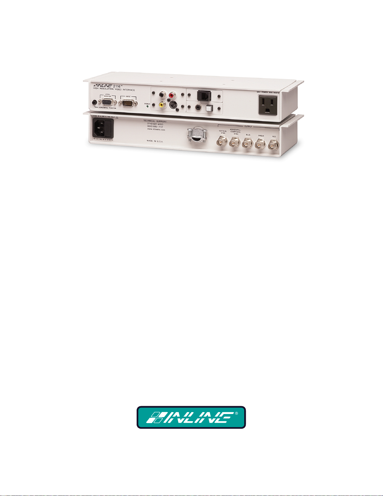
DESCRIPTION
The IN2116 is a high performance computer video interface for analog video signals including VGA,
SVGA, XGA, MAC, SUN and other high-resolution workstations. The IN2116 combines high-resolution
computer interfacing and modular A/V connector plates into a unit that mounts neatly under a conference or
boardroom table, computer workshop, or a podium using integral mounting brackets and (4) #6 wood screws
(included). The unit can also be configured with an optional audio buffer module that converts unbalanced
stereo audio signals to balanced stereo audio. This highly integrated approach gives audiovisual
professionals the ability to quickly design and install functional, customized computer interfacing and A/V
connectivity solutions for a broad spectrum of applications.
Like other INLINE interfaces, the IN2116 performs the following functions:
• Signal Splitting - allows the simultaneous connection and viewing of both the computer’s local monitor
and a second output device such as an LCD data projector or a presentation monitor.
• Physical Interfacing - Because computers employ many different types of video output connectors, it is
sometimes difficult to directly connect them to data projection devices. The IN2116 simplifies
interfacing, routing and switching tasks by acting as a universal adapter. Through the use of removable
input cables, the IN2116 can be attached to different computers and will provide a video output signal
on five BNC connectors. The output signal may be set to RGBHV (default), RGBS or RGsB formats.
The IN2116 is not a scan converter. The data projector, monitor or other output device
must be compatible with the horizontal scan rate output by the computer video card.
PRODUCT FEATURES
Easy Operation - The user simply brings in a computer and connects to the nearest IN2116 table
mountable interface. The IN2116 includes a front panel A/C convenience outlet to power a laptop
computer. Tucked away under the table or podium shelf, the IN2116 provides easy access for making
computer and A/V connections, reduces equipment clutter and com pliments the décor of boardroom,
conference room and training room installations.
15-Pin HD VGA Standard Connectors - The IN2116 connects directly to VGA graphics cards and
VGA local monitors using high-resolution coaxial VGA extension cables such as the IN8000 series. Input /
output adapter cable sets (see table on page 5) are also available in a variety of lengths for MAC (15-Pin D),
SUN (13W3) and workstations (4 or 5 BNC).
IN2116 OPERATION MANUAL - PRELIMINARY 01/21/02 ©1999 - INLINE, INC.
Page 7

3
Modular A/V Connector Plates - In addition to its interface capability, the IN2116 also acts as a
modular A/V connector plate. The IN2116 front panel accepts up to four A/V connector modules, available
with a variety of popular connectors. Two of the most commonly used modules for table mounted
installations are the RJ45 jack (for quick access to the computer network) and the 3.5mm stereo mini or dual
RCA jacks (to connect the computer’s sound card output to the room’s sound system). The IN2116 can hold
double size connector plates to accommodate large connectors such as XLR. The IN2116 simplifies the
design and installation process since a single unit fills the function of both video interface and A/V
connector plate. Available A/V modules are listed on pages 11-12.
Ultra High-Resolution Amplification - The IN2116 provides superb performance and maximum image
clarity at any resolution. Several design elements combine to provide this level of performance: video
bandwidth in excess of 400 MHz, buffered local monitor output, and input / local monitor output cables
constructed of high-resolution coaxial materials.
Stereo Audio Signal Balancing - The IN2116 can be ordered with a IN9370 Balanced Audio Buffer
Module. An optional factory installed module, the IN9370 takes an unbalanced stereo audio signal (applied
to a 3.5mm stereo mini or other front panel audio connector) and converts it to balanced audio. Balanced
audio signals are output in a 5-pin captive screw terminal connector.
CRT / LCD / DMD / ILA / HDLV / Plasma Friendly Output Signal - Dipswitches are available to
set the output sync format, polarity and horizontal position control characteristics as needed to match the
requirements of virtually any compatible data display device.
Selectable Output Sync Format - The unit can be set for RGBHV, RGBS or RGsB output sync as
required by the data display device and signal distribution system. The IN2116 does not strip green off the
sync signal (i.e. RGsB input signals appear at the output as RGsB).
Convenient Controls and Features - A hand-adjustable horizontal position control on the IN2116
front panel allows for precise centering of the image within the data display area. The dipswitch access
plate, located on the underside of the interface, provides quick access to the dipswitches for setting the
output sync format, sync polarity mirroring, serration pulse enable / disable, and VGA / MAC monitor
emulation enable / disable.
In addition the IN2116 features:
• Analog Interface - the unit will operate with Analog Video with TTL level sync signals. The signal can
be separate H & V or composite sync.
• Monitor Emulation Switch - eliminates the need for a termination plug if a local monitor is not used.
Emulates a color VGA monitor or a 13/14” 640 x 480 MAC monitor.
• Sync Polarity Preservation Switch - enables the sync polarity to be preserved, or to be set for negative
polarity (for RGBHV signals in and out).
• Serration Pulse Removal Switch - (for RGBS or RGsB output) enables the user to remove serration
pulses from the sync output.
• Internal Universal Power Supply - plugs directly into any available A/C outlet.
• Available in Two Finishes - IN2116B - Black. IN2116W - White (PMS Cool Grey 3).
©1999 - INLINE, INC. IN2116 OPERATION MANUAL - PRELIMINARY 01/21/02
Page 8

4
Compatibility
INPUT
The IN2116 will accept high-resolution video signals from virtually any computer that outputs an analog
video signal (VGA, SVGA, XGA, MAC, SUN, SGI and other high-resolution computers) at virtually any
refresh rate. Input signal compatibility parameters are:
Video Signal: Analog RGB Video
Signal Format: RGBHV, RGBS, RGsB*
Horizontal Frequency Range: 30 KHz to 130 KHz
Vertical Refresh Rates: 30 Hz to 120 Hz
* The IN2116 will operate with RGsB input signals. However, the unit will not strip sync
off of the green. RGsB input signals are always output as RGsB (they cannot be output
as RGBS or RGBHV). Also, the horizontal position control will not operate when used
with RGsB input signals.
OUTPUT
The output signal of the IN2116 is analog RGB video with TTL sync on 3, 4 or 5 female BNC connectors.
The output format can be set to RGBHV, RGBS or RGsB using dipswitches. This output signal is
compatible with high-resolution data grade monitors and data / graphics projectors.
VGA, MAC, SUN, SGI and other high-resolution workstations operate in several video
modes encompassing a wide range of resolutions and scan rates. Many of the video
signals from the newest models can run as high as 70 KHz or more, with the newest
VGA cards offering an output resolution of 1600 x 1200 (some can even go as high as
1920 x 1080). The data projector or monitor connected to the interface output must be
compatible with the horizontal scan rate and vertical refresh rate of the computer’s
video signal. Please check the documentation for both the computer graphics card and
the data display device to ensure compatibility.
IN2116 OPERATION MANUAL - PRELIMINARY 01/21/02 ©1999 - INLINE, INC.
Page 9

5
ADAPTER / EXTENSION CABLES FOR INPUT AND LOCAL MONITOR OUTPUT
The IN2116 has 15-pin HD VGA-type connectors for input and local monitor output. The following input
and local monitor output cables are available:
Computer 3’ 6’ 12’ 25’
VGA: 15-Pin HD
Input Cable
Output Cable (Optional)
MAC with 15-Pin D:
Input Cable
Output Cable
IN9141 IN9145
MAC G3, G4 and PowerBook with 15-Pin HD*:
Input Cable
Output Cable
SUN: 13W3 (may also be used with SGI with RGsB output)
Input Cable
Output Cable
IN9143 IN9147
Workstation: 5 BNC
Input Cable
Output Cable
Workstation: 4 BNC
Input Cable
IN8006 IN8012 IN8025
IN8006 IN8012 IN8025
IN9140 IN9144
IN8006 IN8012 IN8025
IN8006 IN8012 IN8025
IN9142 IN9146
IN9048 IN9046 IN9046-L25
IN9047 IN9045 IN9046-L25
IN9100
*Newer Mac G3 models (with translucent cases) have 15-Pin HD connectors (pins arranged in 3 rows).
Older G3 models (with solid white enclosures) incorporate 15-Pin D connectors (pins arranged in 2 rows).
Note: The input / output cables listed above can be used with any of the following interfaces, distribution
amplifiers and switchers:
IN2100 IN2200
IN2110 IN3260
IN2111 Series IN3262 Series
IN2112 Series IN3264
IN2114 Series IN3268
IN2116 IN3600 Series
©1999 - INLINE, INC. IN2116 OPERATION MANUAL - PRELIMINARY 01/21/02
Page 10

6
Installation
This section offers step-by-step instructions for installing the IN2116 (see Application Diagram on page 7).
1. Set the dipswitches for the requirements of your installation (see Dipswitch Settings on page 9). The
IN2116 factory default output format is RGBHV. If your display device, routing system or cabling
requires a different format, use the dipswitches to change the output signal to RGBS or RGsB as desired.
2. Utilizing the #6 wood screws (included), mount the unit under a conference or boardroom table,
computer workshop, or a podium using the integral mounting brackets. Run the necessary video coax,
power and accessory cables to it.
3. Connect the IN2116 output (5 BNC connectors) to the data display device’s RGB input, using three, four
or five high-resolution BNC cables or a multi-conductor RGBHV, RGBS or RGB "snake". The IN7000
/ IN7100 / IN7200 / IN7300 Series high-resolution cables and the IN8800 Series installation cables are
well suited for this purpose. While making connections, take care to insure that the red output is
connected to the red input, green output to the green input, etc.
4. Connect the accessory cables as required by your installation.
5. Connect the IN9230 Power Cord (included) to the IN2116. The LED on the front of the unit should
light-up to indicate it is on.
6. Turn the computer and computer monitor off. Disconnect the computer monitor (if present) from the
video output port on the computer.
7. Connect the local computer monitor (if present) to the local monitor output of the IN2116. VGA
monitors will attach directly to the local monitor output. For other types of monitors, use the
appropriate local monitor output adapter cable (see list on page 5). If no local monitor is used, set the
monitor emulation dipswitch to emulate a color VGA monitor or a 13” / 14” MAC RGB monitor (see
Dipswitch Settings on page 9).
8. Connect the output of the computer to the Input of the IN2116 with the appropriate input cable.
9. Complete the installation by turning the computer and computer monitor on. If required, adjust the
horizontal position control.
IN2116 OPERATION MANUAL - PRELIMINARY 01/21/02 ©1999 - INLINE, INC.
Page 11

IN2116 APPLICATION DIAGRAM
FRONT VIEW
OUTPUT
HORIZONTAL/
IN7200-1
Video Cable
IN7000-5/IN7100-5/IN7200-5
IN8800 RGBHV Instalation Cable
Data Projector/
Presentation Monitor
Sound System
IN7200-1
Video Cable
Matrix
Switcher
7
FUSE; 8 A; 250 V; TIME DELAY
125 VAC; 6.4 A; 47-63 HZ
High Resolution Video Interface
HORIZONTAL POSITION
IN8000 series
VGA Extension Cable
LOCAL
MONITOR
2116
INPUT
Audio Cable
TECHNICAL SUPPORT:
(714)921-4100
(800)882-7117
www.inlineinc.com
MADE IN U.S.A.
IN9106
IN7200-1
Video Cable
REAR VIEW
CAT5
LAN Cable
IN8700
Audio Cable
VERTICAL
SYNC
COMPOSITE
SYNC
IN7000-5/IN7100-5/IN7200-5
RGBHV Instalation Cable
GREENBLUE
RED
MAXIMUM POWER: 800W
©1999 - INLINE, INC. IN2116 OPERATION MANUAL - PRELIMINARY 01/21/02
9+69&5
Page 12

8
A/V Connector
o
OUTPUT
HORIZONTAL/
IN2116 FRONT PANEL CONNECTORS AND CONTROLS
High Resolution Video Interface
HORIZONTAL POSITION
Horizontal Position
Control
FUSE; 8 A; 250 V; TIME DELAY
125 VAC; 6.4 A; 47-63 HZ
LOCAL
MONITOR
2116
Input
Connector
INPUT
Output (Buffe red)
Power
Indicator
Local Monitor
TECHNICAL SUP P ORT:
(714)921-4100
(800)882-7117
www.inlineinc.com
MADE IN U.S.A.
Stereo Audi
Input
FRONT VIEW
REAR VIEW
Modules
VERTICAL
SYNC
COMPOSITE
SYNC
MAXIMU M P O WE R: 800W
REDGREENBLUE
Dip Switch
Access Un derne ath U nit l
HORIZONTAL POSITION CONTROL
The location of the horizontal position control is shown above. The horizontal position control adjusts the
position of the image on the data display device from left to right (it has no effect on the local computer
monitor).
Many data projectors and monitors have their own horizontal position control, and the interaction of the
display devices and the interface’s horizontal controls may result in a dark image on the data display. The
following procedure is suggested to ensure best results:
1. Adjust the IN2116 horizontal position control so a good quality image is displayed. This control should
not be set to an extreme position.
2. Adjust the display device’s horizontal position control until the image is centered as desired.
3. If the image appears dark or the colors are not properly displayed, fine tune the controls on both the
display device and the interface until the picture is centered and a good quality image is attained.
IN2116 OPERATION MANUAL - PRELIMINARY 01/21/02 ©1999 - INLINE, INC.
Page 13

9
DIPSWITCH SETTINGS
Most installations will not require any changes to the dipswitch settings, and the IN2116 will generally be
operated with the factory default settings. The factory default and specialized dipswitch settings are
indicated below.
Factory Default Settings:
Dipswitches ON: 2 & 4
Signal Format: Red / Green / Blue / Horizontal and Vertical Sync
Horizontal Position Control: Enabled
H & V Sync Polarity: Negative, Negative
Monitor Emulation: Disabled
The following table lists the functions of the 6 dipswitches:
DIPSWITCH FUNCTION SETTING
1 Horizontal Position
2 RGsB Output (sync on green)
3
RGBS or RGBHV Output (dipswitch
2 must be set to 1)
4 RGBHV Output Sync Polarity
5
6
Serration Pulse Removal (for RGBS
or RGsB output)
Monitor Emulation (VGA
color/MAC* 640 x 480)
1 = Disabled
0 = Enabled
1 = RGBS or RGBHV
0 = RGsB
1 = RGBS
0 = RGBHV
1 = Negative, Negative
0 = Mirror Input Polarities
1 = Remove Serration Pulses
0 = Pass Serration Pulses
1 = Emulation Disabled
0 = Emulation Enabled
*If monitor emulation is desired when using a MAC G3 (with 15-pin HD connector) or G4, dipswitch #6 must be set to 1.
OPTIMAL SETTINGS FOR LCD / DMD / ILA / D-ILA / PLASMA DISPLAYS
The following output sync settings provide maximum signal preservation and are recommended for the best
image quality with LCD, DMD, ILA, D-ILA and Plasma Display devices. Depending on the design of the
display device’s sync processing circuitry, you may be able to set the horizontal position control (dipswitch
#1) to the enabled position. However, experimentation with your display device is the best way to determine
whether you can achieve a stable image with the horizontal position enabled. Many LCD displays include a
fine phase control, which can be adjusted to optimize picture quality.
Dipswitches ON: 1 & 2
Signal Format: Red / Green / Blue / Horizontal and Vertical Sync
Horizontal Position Control: Disabled
H & V Sync Polarity: Mirror Input Polarities
©1999 - INLINE, INC. IN2116 OPERATION MANUAL - PRELIMINARY 01/21/02
Page 14

10
3RZHU*URXQGEOXH
%DODQFHG2XWSXW6LJQDO
6HW----WR&RQQHFW%RWWRP3LQV
IN9370 AUDIO BUFFER MODULE
The IN2116 can be ordered with a IN9370 audio buffer module. This factory installed optional module
takes an unbalanced stereo audio input, buffers the signal and outputs it as balanced stereo audio. This is
desirable for systems where the IN2116 audio signal will be connected to equipment with balanced audio
inputs, and is helpful in preserving signal integrity and minimizing outside signal interference (which often
occurs while sending the audio signal over lengthy cable runs). The output can also be set for unbalanced
stereo audio if desired.
IN9370 Input Signal Factory Pre-Wiring
In the factory default installation, the IN9370 is pre-wired to accept unbalanced stereo audio input from a
3.5mm stereo mini audio input connector located on one of the four A/V connector modules (any
alternative-wiring / connector configurations must be requested at time of order).
IN9370 Jumper Settings
J2 and J3 set the output for either balanced or unbalanced audio signals. J4 balances or unbalances the left
side audio signal, and J5 balances or unbalances the right. All four jumpers (J2, J3, J4 and J5) need to be set
in the same position.
Balanced Output Signal: Set J2 / J3 / J4 / J5 to Connect Bottom 2 Pins
Unbalanced Output Signal: Set J2 / J3 / J4 / J5 to Connect Upper 2 Pins
Note: Connections to J1 and J7 are pre-wired at the factory and may only be modified by trained
technicians. J7 is used for power input, and J1 is the audio input.
IN9370 Output Connector
A balanced or unbalanced stereo audio output signal is provided on a 5-pin captive screw connector. It is
important that connections are made appropriately for balanced or unbalanced output as indicated in the
diagram below:
PP0LQL6WHUHRFRQQHFWLRQ
5LJKW*URXQG
/HIW*URXQG
5LJKW*URXQG
/HIW*URXQG
5LJKW
/HIW
5LJKW
5LJKW
/HIW
/HIW
9GFUHG
9GFEODFN
-
-
%
D
O
8QEDODQFHG2XWSXW6LJQDO
8
Q
E
6HW----WR&RQQHFW8SSHU3LQV
D
O
%
D
O
8
Q
G
E
H
D
O
F
Q
-
D
O
D
E
Q
8
%
D
O
G
H
F
Q
D
O
D
%
8
Q
E
D
O
-
)DFWRU\'HIDXOWLV%DODQFHG2XWSXW
%
D
O
8
Q
-
E
D
O
IN2116 OPERATION MANUAL - PRELIMINARY 01/21/02 ©1999 - INLINE, INC.
Page 15

11
AUDIO / VIDEO / PHONE / DATA / SWITCH / COMPUTER CONNECTOR MODULES
Modular A/V Connector Plates & Accessories for:
IN2111 Series / IN2112 Series / IN2114 Series / IN2116 / IN3260 / IN9166 / IN9167 / IN9168
Connector Module
Black/White
IN9350B / IN9350W Blank Plate - Single Size None None Single
IN9351B / IN9351W (2) BNC Barrel (2) BNC Female (2) BNC Female Single
IN9352B / IN9352W (1) S-Video 4-pin Mini DIN Female 4 Bare Wires Single
IN9353B / IN9353W (2) RCA
IN9354B / IN9354W (2) ¼” Stereo Phono (2) ¼” Stereo Phono Female (3) Solder Lug Terminals Single
IN9355B / IN9355W (2) 3.5mm Mini Stereo (2) 3.5mm Mini Stereo Female (3) Solder Lug Terminals Single
IN9356B / IN9356W
IN9357B / IN9357W (2) F-Connector Barrel (2) F-Connector Female (2) F-Connector Female Single
IN9358B / IN9358W (1) RJ11 RJ11 Female - Leviton Brand 6-pin Punch Block Single
IN9359B / IN9395W (1) RJ45 RJ45 Female - Leviton Brand
IN9360B / IN9360W
IN9361B / IN9361W (1) 15-pin HD 15-pin HD Female 15-pin HD Female Single
IN9362B / IN9362W (1) 15-pin HD 15-pin HD Male 15-pin HD Male Single
IN9363B / IN9363W
IN9364DB /
IN9364DW
IN9365DB /
IN9365DW
IN9366DB /
IN9366DW
IN9367DB /
IN9367DW
IN9372DB /
IN9372DW
IN9373B / IN9373W (2) RCA Barrel (2) RCA Female (2) RCA Female Single
IN9374B / IN9374W
Description
(1) 5-PIN Captive Screw
Terminal
(1) Contact Closure
Switch With LED &
(1) 3.5mm Mini Stereo
(1) S-Video Barrel &
(1) BNC Barrel
(1) 4-pin XLR
(1) 3-pin XLR
(1) 6-pin XLR
Blank Plate - D ouble None None Double
A/V Super Module:
(2) RCA - Audio &
(1) RCA - Video &
(1) S-Video
(1) 9-Pin D Gender
Changer – Female
Front Connector /
Termination
(1) RCA Female - Red
(1) RCA Female - Black
Phoenix Brand 5-pin
Captive Screw Terminal
Square White Single Pole
Switch with Integrated LED
3.5mm Mini Stereo Female (3) Solder Lug Terminals
4-pin Mini DIN Female 4-pin Mini DIN Female
BNC Female BNC Female
Neutrik Brand 4-pin XLR
Female
Neutrik Brand 3-pin XLR
Female
Neutrik Brand 6-pin XLR
Female
RCA Female - Red (2) Solder Lug Terminals
RCA Female - Black (2) Solder Lug Terminals
RCA Female - Yellow (2) Solder Lug Terminals
4-pin Mini DIN Female 4 Bare Wires
(1) 9-pin D Female (1) 9-pin D Female Single
Back Connector /
Termination
(2) Solder Lug Terminal
(2) Solder Lug Terminals
(5) Solder Lug Terminals Single
8-pin Punch Block for
Cat 5 Cable
(4) Solder Lug Terminals
(4) Solder Cups Double
(3) Solder Cups Double
(6) Solder Cups Double
Module
Size
Single
Single
Single
Single
Double
©1999 - INLINE, INC. IN2116 OPERATION MANUAL - PRELIMINARY 01/21/02
Page 16

12
Connector Module
Black/White
IN9375B / IN9375W
IN9376B / IN9376W
IN9377DB /
IN9377DW
IN9378B / IN9378W
IN9381B / IN9381W (1) BNC Barrel (1) BNC Female (1) BNC Female Single
IN9382B / IN9382W (1) F-Connector Barrel (1) F-Connector Female (1) F-Connector Female Single
IN9383B / IN9383W (1) RCA Barrel (1) RCA Female (1) RCA Female Single
IN9384B / IN9384W (1) ¼” Stereo Phono (1) ¼” Stereo Phono Female (3) Solder Lug Terminals Single
IN9385B / IN9385W (1) 3.5mm Mini Stereo (1) 3.5mm Mini Stereo Female (3) Solder Lug Terminals Single
IN9386B / IN9386W
IN9387B / IN9387W
IN9388B / IN9388W
IN9389B / IN9389W
IN9394DB /
IN9394DW
IN9395DB /
IN9395DW
IN9396DB /
IN9396DW
Description
(2) Keyboard / Mouse
Connectors
A/V Super Module with
Barrel Connectors:
(2) RCA - Audio &
(1) RCA - Video &
(1) S-Video
(2) RCA - Audio &
(1) RCA - Video
(1) 9-pin D Gender
Changer - Male
(1) BNC Barrel &
(1) 3.5mm Mini Stereo
(1) S-Video &
(1) 3.5mm Mini Stereo
(1) RCA for Video &
(1) 3.5mm Mini Stereo
(1) 6-PIN Mini DIN
Barrel
(PS/2 Keyboard /
Mouse)
(1) 4-pin XLR Switchcraft 4-pin XLR Female (4) Solder Cups Double
(1) 3-pin XLR Switchcraft 3-pin XLR Female (3) Solder Cups Double
(1) 6-pin XLR Switchcraft 6-pin XLR Female (6) Solder Cups Double
Front Connector /
Terminal
(2) 6-pin Mini DIN Female
RCA Female - Red RCA Female
RCA Female - Black RCA Female
RCA Female - Yellow RCA Female
4-pin Mini DIN Female 4-pin Mini DIN Female
RCA Female - Red (2) Solder Lug Terminals
RCA Female - Black (2) Solder Lug Terminals
RCA Female - Yellow (2) Solder Lug Terminals
(1) 9-pin D Male (1) 9-pin D Male Single
BNC Female BNC Female
3.5mm Mini Stereo (3) Solder Lug Terminals
4-pin Mini DIN Female 4 Bare Wires
3.5mm Mini Stereo (3) Solder Lug Terminals
Yellow RCA Female (2) Solder Lug Terminals Single
(1) 6-pin Mini DIN Female
Back Connector /
Terminal
(2) 6-pin Mini DIN
Female
(1) 6-pin Mini DIN
Female
Module
Size
Single
Double
Double
Single
Single
Single
Note: When ordering the IN2116, please specify the necessary A/V connector modules.
IN2116 OPERATION MANUAL - PRELIMINARY 01/21/02 ©1999 - INLINE, INC.
Page 17

13
Specifications
Input
Connector Type 15-pin HD male - standard VGA pin-outs
RGB Video Signals Analog, 1.5 Vp-p max.
Input Impedance 75 ohm
Sync Signals TTL compatible
Horizontal Scan Rate 30 KHz - 130 KHz
Vertical Scan Rate 30 Hz - 120 Hz
Output
Buffered Local Monitor 15-pin HD female - standard VGA pin-outs
Stereo Audio Output with
IN9370 Installed (Buffered)
Main Output 5 BNC female connectors
Output Signal Formats
RGBHV - Mirror input sync polarities, RGBS or RGsB
RGB Signals Analog Video, 75 ohm impedance
Bandwidth 400 MHz @ -3 dB with .7 volt input signal
Rise and Fall Times 0.875 nano seconds
Gain 1.0 +/- 5% (unity)
Sync Signal
H, V and S: 4V Unterminated; 2V when 75 ohm terminated
Horizontal Position Enabled: Approximately 1.5 usec
Horizontal Pulse Width
Horizontal Position Deleted: Approximately the same
Vertical Pulse Width Approximately the same as the input signal
Controls
External Dipswitches located underneath the unit
Internal 75 ohm / High Z termination for red, green and blue (3 jumpers)
Dimensions
Size (including faceplate) 1.8” H x 12.5” W x 4.78” D / 4.6cm x 31.7cm x 12.1cm
Shipping Weight 4 lbs. / 2 kg.
Power
Power Supply Internal Switch Mode Power Supply
Front Panel A/C Outlet
Regulatory Compliance
Safety
EMI
FCC class A; CE: EN50022 (1987), EN50081-1 (1991),
5-pin Phoenix captive screw terminal
RGBHV - Negative sync polarities (default)
Gs: 0.3V when 75 ohm terminated
as the input signal
U.S. Version: Edison Female - 800 Watts Max.
Call for A/C Outlet Connector Information
on British, European and Australian Models
UL 1950. 3
CAN/CSA-22.2 No. 950 3
rd
Ed.; CE: EN50081-1
rd
Ed.
EN50082-1 (1992 & 1994), EN60950-92
©1999 - INLINE, INC. IN2116 OPERATION MANUAL - PRELIMINARY 01/21/02
Page 18

14
Parts Included
(1) IN2116 Table Mountable Installation Interface
(1) IN9334 3/32 Allen Wrench for IN2116 Connector Module Set Screws
(1) IEC Power Cable
(1) Operation Manuel
Required Accessories (Ordered Separately)
Input and Local Monitor Adapter and Extension Cables:
VGA: IN8000 Series 15-pin HD male to 15-pin HD female, various lengths from 3’ to 100’
For Other Computers: See list on page 4
Optional Accessories
Balanced Audio Module
IN9370: Audio Buffer Module - converts unbalanced stereo audio signals to balanced audio. The IN9370
input is normally connected to the 3.5mm audio input connector. The module may also be wired
to accept stereo audio input from RCA, 3.5mm mini or ¼” connector modules.
Audio Input Cables (for use with optional IN9370 with 3.5mm input connector):
IN9106: 3.5mm stereo mini male to 3.5mm stereo mini male, 6’ long
IN9107: (1) 3.5mm stereo mini male to (2) RCA male, 6’ long
Installation Cables
IN7000P-5 Series RGBHV Cable:
Standard Resolution, Plenum Cable available in bulk lengths
IN7000P-5K Series RGBHV Cable: Standard Resolution, Plenum Cable available in 1000’ bulk length
IN8800: 18 Conductor Super High-Resolution Cable: (3) Super High-Res. Coax., (3) Mini Coax.,
(5) 26 Gauge Twisted Pairs, (1) Gauge Pair
Connectors and Tools:
IN9301 BNC Connectors
IN9320 Crimp Tool Frame
IN9321 Die (IN9320 and IN9321 are used to terminate bulk cables)
RGB OUTPUT CABLES
Cables 3-Conductor 4-Conductor 5-Conductor 6-Conductor
Standard Resolution IN7000-4 IN7000-5
Standard Resolution, Plenum IN7000P-4 IN7000P-5
High Resolution
Ultra High Resolution
Super High Resolution IN7300-5 IN7300-6
Super High Resolution, Plenum
All cable grades are available in lengths from 3’ to 250’ pre-terminated with high quality BNC connectors or as bulk cable.
IN2116 OPERATION MANUAL - PRELIMINARY 01/21/02 ©1999 - INLINE, INC.
IN7100-3 IN7100-4 IN7100-5
IN7200-3 IN7200-4 IN7200-5 IN7200-6
IN7300P-6
Page 19

15
Troubleshooting
The display device connected to the IN2116 output has a bad / scrambled image.
Solution 1: Verify that the correct input cable is being used (see list on page 5).
Solution 2: The display device connected to the output of the interface may not be compatible with the
computer output. Standard 640 x 480 VGA runs at 31.5 KHz, and SVGA can be as high as
48 - 58 KHz, depending on the vertical refresh rate. PC, MAC, SUN and other highresolution workstations have new and ultra high-resolution modes such as 1600 x 1200 and
1800 x 1440, and can output a video signal with a horizontal scan rate of over 100 KHz!
Many data monitors and data projectors are not compatible with these resolutions and
frequencies.
Solution 3: Check the dipswitch settings to make sure the unit is putting out a sync format that the display
device can use. For most applications, the default dipswitch settings (see page 9) will work
best. For LCD / DMD displays, you may have to disable the horizontal position control.
Solution 4: The RGBS or RGBHV cable may have a bad sync line. Try running the sync through another
cable.
Solution 5: The IN2116 output sync range may not be compatible with the display device. Check the
resolution and refresh rate for both the computer graphics card and the data display device
to ensure compatibility.
The output image is very dark.
Solution: The horizontal position control may be set off to an extreme setting or may be interacting
poorly with the horizontal position control on the display device. Follow the horizontal
position adjustment procedure on page 8.
The local monitor looks fine but the image on the LCD projector is wavy or has vertical bars in the
picture.
Solution 1: LCD / DMD displays work best when the sync signal has minimum sync processing. Set the
interface dipswitches as indicated in the section OPTIMAL SETTINGS FOR LCD /
DMD DISPLAYS on page 9. Setting the interface to RGBHV output and disabling the
horizontal position control may alleviate this problem.
Solution 2: LCD / DMD displays often have an adjustment called Phase Adjust or Fine Phase Control.
This control should be adjusted to provide the best image.
The output image is missing a color.
Solution: Possibly the RGBS or RGBHV cable is bad. Try switching connections on the output to verify
that the bad color’s cable is OK (Example: If there is no red, try running the green output
through the red cable and see if the green is displayed or not).
The output image is too green.
Solution: The dipswitch settings may be set for sync on green output and the display device doesn’t like
that format. Try changing the dipswitches to output an RGBS or RGBHV signal (see
dipswitch settings on page 9).
The horizontal position control is not working.
Solution 1: Check the dipswitch settings (page 9) to see if the horizontal position control has been disabled.
Solution 2: The input setting may be RGsB (sync on green). The horizontal position control does not work
with RGsB input signals.
©1999 - INLINE, INC. IN2116 OPERATION MANUAL - PRELIMINARY 01/21/02
Page 20

16
The output image is doubled, with two images displayed side-by-side.
Solution: The display device may not be compatible with the horizontal scan rate of the computer. This
problem often occurs when a 31.5 KHz VGA signal is sent into an RGB monitor that is only
compatible with signals at 15.75 KHz.
If problems persist, call INLINE Technical Services at (800) 882-7117 for further assistance.
Warranty
♦
INLINE warrants the equipment it manufactures to be free from defects in materials and
workmanship.
♦
If equipment fails because of such defects and INLINE is notified within three (3) years from the date
of shipment, INLINE will, at its option, repair or replace the equipment at its plant, provided that the
equipment has not been subjected to mechanical, electrical or other abuse or modifications.
♦
Equipment that fails under conditions other than those covered will be repaired at the current
price of parts and labor in effect at the time of repair. Such repairs are warranted for ninety (90)
days from the day of re-shipment to the Buyer.
♦
This warranty is in lieu of all other warranties expressed or implied, including without
limitation, any implied warranty or merchantability or fitness for any particular purpose, all
of which are expressly disclaimed.
The information in this manual has been carefully checked and is believed to be accurate. However,
INLINE, Inc. assumes no responsibility for any inaccuracies that may be contained in this manual. In n o event will
INLINE, Inc. be liable for direct, indirect, special, incidental, or consequential damages resulting from any defect or
omission in this manual, even if advised of the possibility of such damages. The technical information contained
herein regarding IN2116 features and specifications is subject to change without notice.
IBM is a registered trademark of Internatio nal Busin ess Machines. App le, MAC, Quadra an d Centri s are registered
trademarks of Apple Computers, Inc. Iris Indigo is a registered trademark of Silicon Graphics. Sun Sparc Station is
a registered trademark of Sun Microsystems, Inc. All other trademarks and registered trad emarks are the property of
their respective companies.
All Rights Reserved © Copyright 1999
©
INLINE, INC. ♦ 810 WEST TAFT ♦ ORANGE, CA 92865
(800) 882-7117 ♦ (714) 450-1800 ♦ FAX (714) 450-1850 ♦ www.inlineinc.com
IN2116 OPERATION MANUAL - PRELIMINARY 01/21/02 ©1999 - INLINE, INC.
Page 21

12.50“
IN2116FrontView
11.75“
IN2116TopView
1.80“
2.390“
1.195“
4.78“
MountingHoles:0.156“/4mmDiameter
(4)#6WoodScrewsIncluded
12.125“
0.187“
 Loading...