

Page 1
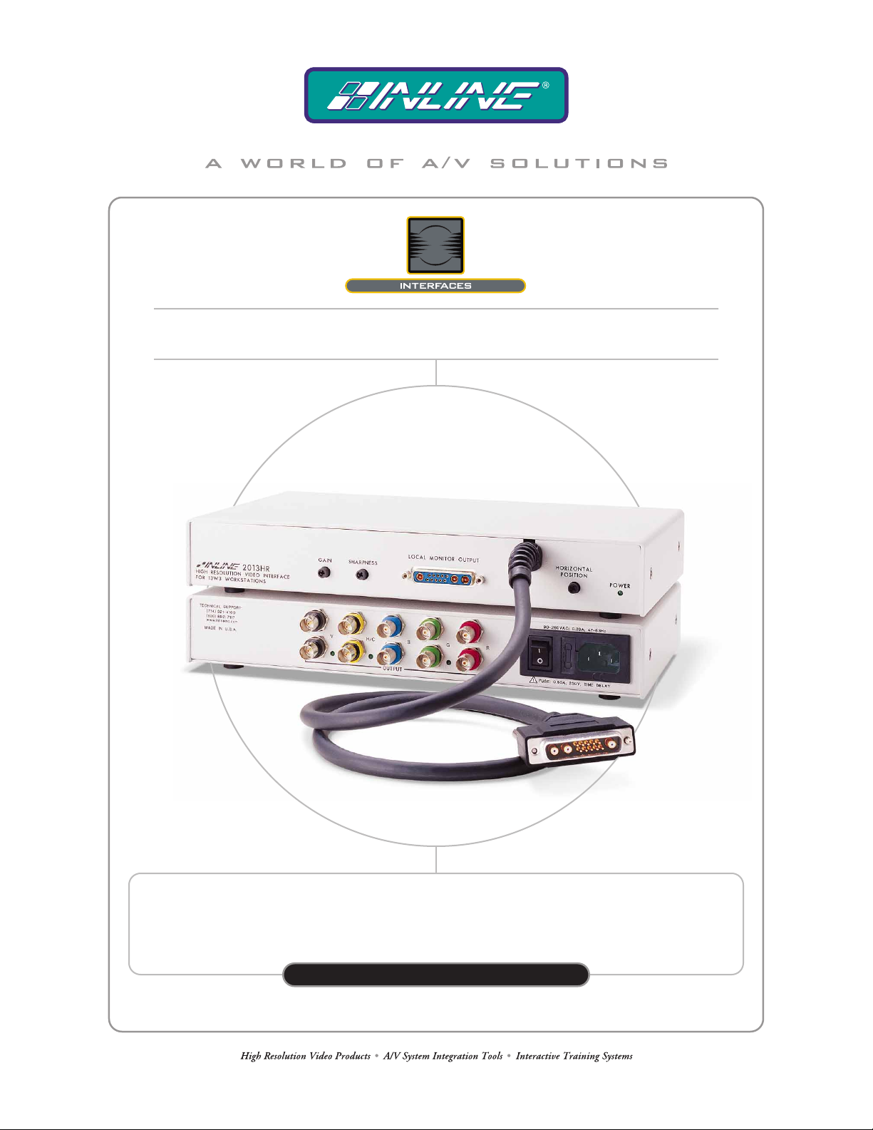
IN2013HR HIGH RESOLUTION VIDEO INTERFACE
FOR 13W3 WORKSTATIONS
IN2013HR
OPER AT ION MANUAL
Page 2
Installation and Safety Instructions
For Models without a Power Switch:
The socket outlet shall be installed near the equipment and shall be accessible.
For all Models:
No serviceable parts inside the unit. Refer service to a qualified technician.
For Models with Internal or External Fuses:
For continued protection against fire hazard, replace only with same type and rating of fuse.
Instructions d’installation et de sécurité
Pour les modèles sans interrupteur de courant:
La prise de courant d’alimentation sera installé près de l’équipement et sera accessible.
Pour tout les modèles:
Pas de composants à entretenir à l’intérieur. Confiez toute réparation à un technicien qualifié.
Pour les modèles équipés de fusibles internes ou externes:
Afin d’éviter tout danger d’incendie, ne remplacer qu’avec le même type et la même valeur de fusible.
Installations- und Sicherheitshinweise
Für Geräte ohne Netzschalter:
Die Netzsteckdose soll in der Nähe des Gerätes installiert und frei zugänglich sein.
Für alle Geräte:
Keine Wartung innerhalb des Gerätes notwendig. Reparaturen nur durch einen Fachmann!
Für Geräte mit interner oder externer Sicherung:
Für dauernden Schutz gegen Feuergefahr darf die Sicherung nur gegen eine andere gleichen Typs und gleicher Nennleistung
ausgewechselt werden.
Instalacion E Instrucciones de Seguridad
Modelos Sin Interruptor:
Para Todos Los Modelos:
Modelos con Fusibles Internos o Externos:
La conexión debe ser instalada cerca del equipo y debe ser accesible.
Dentro de la unidad , no hay partes para reparar. Llame un tecnico calificado.
Para prevenir un incendio, reemplace solo con el mismo tipo de fusible.
CE COMPLIANCE
All products exported to Europe by Inline, Inc. after January 1, 1997 have been tested and found to
comply with EU Council Directive 89/336/EEC. These devices conform to the following
standards:
EN50081-1 (1991), EN55022 (1987)
EN50082-1 (1992 and 1994), EN60950-92
Shielded interconnect cables must be employed with this equipment to ensure compliance with
the pertinent Electromagnetic Interference (EMI) and Electromagnetic Compatibility (EMC)
standards governing this device.
FCC COMPLIANCE
This device has been tested and found to comply with the limits for a Class A digital device,
pursuant to Part 15 of the FCC rules. These limits are designed to provide against harmful
interference when equipment is operated in a commercial environment. This equipment generates,
uses and can radiate radio frequency energy and, if not installed and used in accordance with th e
instruction manual, may cause harmful interference to radio communications. Operation of
equipment in a residential area is likely to cause harmful interference, in which case the user will be
required to correct the interference at their own expense.
Page 3

1
Product Overview
DESCRIPTION
The IN2013HR is a high performance dedicated computer video interface for Sun, SGI, IBM
PowerPC, NeXT, and other graphic workstations with 13W3 video ports. Like other INLINE
interfaces, the IN2013HR performs the following functions:
• Signal Splitting - allows the simultaneous connection and viewing of both the
computer’s local monitor and a second output device such as a large screen data projector
or presentation monitor.
• Physical Interfacing and Adaptation - Because computers employ many different
types of video output connectors, it is sometimes difficult to directly connect them to
data projection devices. The IN2013HR connects to workstations with special video
connectors (13W3) and provides an output signal on standard BNC connectors.
• Electronic Interfacing - The interface accepts video in a wide variety of sync formats
and converts the signal to RGsB, RGBS, RGBHV or Composite Monochrome as
required by the display device, cabling, and video routing system.
PRODUCT FEATURES
Universal Compatibility for Graphic Workstations with 13W3 Video Ports - Factory set for
automatic operation with Sun and SGI computers, the unit will accept other workstation signals
by adjusting one or two dipswitches.
Exceptional Video Performance - Featuring advanced video amplification circuitry, the
IN2013HR offers a video bandwidth of 230 MHz, ensuring that even the highest resolution
workstation video signals will be interfaced with complete signal clarity.
Local Monitor Output - provides a buffered signal for the local computer monitor.
Automatic Output Sync Format Selection - The IN2013HR senses the number of cables
connected to the outputs at power up and automatically sets the output sync format to RGsB,
RGBS, RGBHV or Composite Monochrome.
Dual Outputs - the IN2013HR can drive two display devices in addition to the local monitor.
Flexible Monitor Emulation - The interface automatically sets itself to the appropriate
resolution / refresh rate, or can be used without a local display device (dipswitches are provided
to emulate virtually any monitor).
©2000 - INLINE, Inc. IN2013HR Operation Manual - V1.0 12/05/00
Page 4
2
Convenient Controls - The IN2013HR offers intuitive front panel controls for the most
important signal adjustments.
• Gain Control - adjusts the voltage level of the RGB components simultaneously
(ensuring that gray scale is maintained), and may be used to compensate for signal loss
due to long cable runs.
• Sharpness Control - provides effective image enhancement for high-resolution video
signals by increasing clarity and edge detail.
• Horizontal Position Control - allows the picture to be centered precisely on the data
display screen.
The IN2013HR is not a scan converter. The data projector, monitor or
other output device must be compatible with the horizontal scan rate,
vertical scan rate and resolution output by the computer video card.
Compatibility
INPUT
The IN2013HR will accept high-resolution video signals from Sun SPARC, Silicon Graphics,
IBM PowerPC, NeXT and virtually any other graphic workstation that outputs analog video
through a 13W3 female connector. Input signal compatibility parameters are:
Video Signal: Analog RGB Video
Connector: 13W3 female video port on computer
Signal format: RGsB, RGBS, RGBHV
Horizontal Frequency Range: 30 KHz to 130 KHz
Vertical Refresh Rates: 50 Hz to 120 Hz
OUTPUT
The IN2013HR outputs an analog RGsB, RGBS, RGBHV or Composite Monochrome signal on
female BNC connectors. This output signal is compatible with high-resolution data grade
monitors and data / graphics projectors. Graphic workstations operate in several video modes
encompassing a wide range of resolutions and scan rates. Many workstation video signals run as
high as 70 KHz or more, with the newest workstations offering output resolutions as high as
1920 x 1080. The data projector or monitor connected to the interface output must be compatible
with the horizontal scan rate and vertical refresh rate of the computer’s video signal. Check the
documentation for both the computer graphics card and the data display device to ensure
compatibility.
IN2013HR Operation Manual - V1.0 12/05/00 ©2000 - INLINE, Inc.
Page 5
3
Installation
This section offers step-by-step instructions for installing the IN2013HR Computer Video
Interface. An Application Diagram is included on page 5.
1. Turn the Computer and Computer Monitor Off - Disconnect the computer monitor from
the computer’s video port.
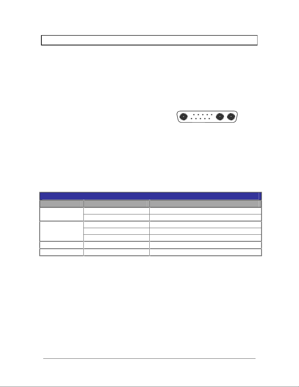
2. Connect the Permanently Attached IN2013HR Input Cable - to the computer’s video output
port (see illustration on the right). For cable
runs that are longer than 3’, the IN8400
Series 13W3 Workstation Extension Cables
are available in lengths ranging from 6’ to
50’.
3. Check the Input Signal Configuration Settings - (SWITCH 1 - Dipswitches 8 / 9 / 10)
which are on the bottom of the IN2013HR. The factory default settings for dipswitches 8, 9
and 10 will work with Sun workstations and most SGI computers. For other computers,
carefully set dipswitches 8, 9 and 10 as indicated in the chart below:
Note: These settings only relate to the input signal from the computer and have no effect on the
output sync format.
Computer Input Selection Dipswitch Chart
Workstation Input Signal 8/9/10 Dipswitch Setting - Switch Bank 1
SUN
SGI
RGBS (most common) 000 - Composite Sync on pin 5
RGBHV 101 - Hor. sync on pin 6; Vert. sync on pin 2
RsGsBs (most common) 001 - Sync on green
RGBS 011 - Composite Sync on pin 3
RGBHV 100 - Hor. sync on pin 4; Vert. sync on pin 5
NeXT Color
IBM PowerPC
RGsB 001 - Sync on green
RGBHV 010 - Hor. sync on pin 5; Vert. sync on pin 9
4. Connect the IN2013HR Video Output - (5 BNC connectors) to the data display device's
RGB input, using three, four, or five high-resolution BNC cables or a multi-conductor
RGBHV, RGBS, or RGB "snake". The IN7000 Series, IN7200 Series, IN7300 Series and
IN7400P Series high-resolution cables are well suited for this purpose. Take care while
making connections to insure that the red output is connected to the red input, green output to
the green input, etc.
5. Select the Output Sync Format - The interface normally selects an output format
automatically according to the number of cables connected to the output. If you wish to
override the automatic output format feature and manually select a specific format, set the
dipswitches as necessary according to the chart on page 8 (see Output Sync Format -
Manual Mode).
©2000 - INLINE, Inc. IN2013HR Operation Manual - V1.0 12/05/00
Page 6

4
6. Connect the Local Computer Monitor - (if present) to the IN2013HR local monitor output
port. Check the Monitor Emulation Dipswitch Settings on the bottom of the IN2013HR.
• When Using a Local Monitor - make sure that all dipswitches in the box labeled
MONITOR EMULATION are set to “0”.
• If No Local Monitor is Required - using the IN9339 alignment tool (provided), gently
set the monitor emulation dipswitches according to the Monitor Emulation Dipswitch
Chart provided on page 9.
Check the Monitor Emulation chart and dipswitch settings carefully. Any
improper setting of the emulation dipswitches may lead to improper
operation and could even result in severe damage to the computer video
port or the monitor. If you are in doubt as to which monitor emulation to
choose, set all the Monitor Emulation dipswitches to “0” and connect the
local monitor.
6. Apply Power - to the IN2013HR using the IN9230 IEC power cable (included).
7. Turn On - the computer, the IN2013HR, the local monitor (if applicable) and the display
device. If necessary, adjust the gain, sharpness and / or horizontal position control as
detailed on pages 6 and 7.
IN2013HR Operation Manual - V1.0 12/05/00 ©2000 - INLINE, Inc.
Page 7

5
©2000 - INLINE, Inc. IN2013HR Operation Manual - V1.0 12/07/00
Page 8

6
Front Panel Controls
The IN2013HR features fully automatic operation, however, the interface offers several external
controls that allow users to optimize the unit’s performance to meet the needs of specialized
applications. Gain, sharpness and horizontal position control adjustments are located on the
front of the IN2013HR. Turning the adjustments clockwise will increase the value, and
counterclockwise will decrease it. Each control has an adjustment range of 15 turns.
GAIN CONTROL
The gain control is a small black knob located on the left side of the unit’s front panel. The gain
control adjusts the output voltage of the red, green, and blue outputs simultaneously (ensuring
that gray scale is maintained), and may be used to compensate for signal loss due to long cable
runs. The gain adjustment range is .7 in the minimum position (30% decrease) and 1.3 in the
maximum position (30% increase). The factory default setting is 1.0 (unity gain).
SHARPNESS CONTROL
The IN2013HR sharpness / peaking circuitry provides variable high frequency equalization that
can compensate for high frequency losses due to long output cable runs. The amount of high
frequency boost required will vary depending on the length and bandwidth performance of the
video output cables, and, to a lesser extent, the resolution and frequency of the input signal.
When using short output cables, the sharpness control should usually be placed at the minimum
setting to avoid over-peaking.
The sharpness control is located between the gain control knob and the local monitor output port.
Using the IN9339 Alignment Tool (included), turn the sharpness control clockwise to increase
the sharpness setting, and counterclockwise to decrease the sharpness setting. The factory
default setting is minimum (no sharpness / peaking enhancement). The following guidelines are
useful in selecting the optimal sharpness / peaking setting:
If the image is soft and / or fine details in the picture lack clarity:
The sharpness is probably set too low. Increase the sharpness control setting.
If a white, ghosted image appears to the right side of the lines / characters:
The sharpness is probably set too high (over-peaked). Decrease the sharpness control
setting.
HORIZONTAL POSITION CONTROL
The horizontal position control is a small black knob located adjacent to the front panel power
LED display. This adjustment allows users to shift the position of the image on the data display
device from left to right. The horizontal position control does not effect the local monitor.
If the horizontal position adjustment is set to an extreme position on either the display device or
the IN2013HR, the output image may appear dark and / or the colors may be displayed
improperly. To position the video image and achieve optimum picture quality:
1. Set the display device’s horizontal position control to the center of its adjustment range.
2. Adjust the horizontal position control on the IN2013HR until the picture is centered
properly on the display device.
IN2013HR Operation Manual - V1.0 12/05/00 ©2000 - INLINE, Inc.
Page 9

7
Horizontal Position Control Enable / Disable
The factory default setting is horizontal position control enabled. In rare cases (depending on the
design of the display device sync circuitry), you may have to disable the horizontal position
control to achieve a solid image on the display device. The horizontal position control may be
enabled or disabled by setting the dipswitch 1 in SWITCH Bank 1 as indicated in the chart at the
bottom of the page.
Dipswitch Settings
Two dipswitch panels are easily accessed through windows on the bottom of the IN2013HR. The
SWITCH 1 panel regulates the output sync format (dipswitches 1-7) and controls the input signal
configuration (dipswitches 8-10). The SWITCH 2 panel determines the monitor emulation settings.
SWITCH 1
For most installations, the IN2013HR will be operated in the factory default mode and will not
require any changes to the dipswitch settings. The factory default settings are:
SWITCH 1 Dipswitches ON: 1, 3, 5, 6, 7 & 8
Output Signal Format: Auto Sense Enabled - Interface Selects Format
Horizontal Position Control: Enabled
H & V Sync Polarity: Mirror Input Polarities
Monitor Emulation (SWITCH 2): Disabled (all Dipswitches on SWITCH 2 panel are set to 0)
The following table lists the functions of the first 7 dipswitches in SWITCH 1:
Dipswitch Function Setting
1
2
3
4
5
6
7
Horizontal Position Control
Output Sync Format:
Sync on Green
Output Sync Format
RGBHV / RGBS
Output Sync Polarity
Output Sync Format:
Auto Sense / Manual
Serration Pulses
Output Video Format:
Green / Monochrome Video
1 = Enabled*
0 = Disabled
1 = Sync on Green
0 = RGBHV / RGBS*
1 = RGBHV*
0 = RGBS
1 = Forced Negative
0 = Mirror Input*
1 = Auto Sense*
0 = Manual
1 = Serrations Present*
0 = No Serrations
1 = Green*
0 = Monochrome on Green BNC
*Factory Default Settings
©2000 - INLINE, Inc. IN2013HR Operation Manual - V1.0 12/05/00
Page 10

8
OUTPUT SIGNAL FORMAT SELECTION
Output Format: Automatic Sense Mode (Dipswitch 5 = 1)
In factory default configuration, the IN2013HR automatically senses the number of cables connected
to the output BNC connectors and selects an appropriate output signal format. LED indicators located
next to the V/Sync, H/Comp Sync and Green output BNCs (on the back of the interface) provide clear
visual confirmation of the current output sync format. In order for output format auto sense circuit to
operate, dipswitch 5 on Switch Bank 1 must be set to 1.
Number of Cables Connected to Output Output Format
(3) Cables connected to RGB BNCs RGsB
(4) Cables connected to RGBS BNCs RGBS
(5) Cables connected to RGBHV BNCs RGBHV
Output Sync Format : Manual Mode (Dipswitch 5=0)
For some applications, you may wish to force the interface to operate in a specific output format.
To set the output sync format manually, you must first disable the auto sense circuit by setting
dipswitch 5 on Switch Bank 1 to 0. Next, set dipswitches according to the table below to select
the desired output format.
Output Format Dipswitch Settings
(Switch Bank 1)
RGBHV (Factory Default) 2 = 0
3 = 1
5 = 0
RGBS 2 = 0
3 = 0
5 = 0
RGsB 2 = 1
3 = 1
5 = 0
7 = 1
Composite Monochrome on Green BNC 2 = 1
3 = 1
5 = 0
7 = 0
INPUT SIGNAL FORMAT SELECTION
The IN2013HR is set at the factory for automatic operation with SUN and most SGI computers
(*dipswitches 8 / 9 / 10 off). For other computers or signal formats, carefully set dipswitches 8, 9 and
10 as indicated in the chart below
INPUT SIGNAL CONFIGURATION - SWITCH BANK 1
DIPSWITCH SUN
RGBS*
8 0 1 0 0 1 0
9 0 0 0 1 0 1
10 0 1 1 1 0 0
*Factory Default Settings
IN2013HR Operation Manual - V1.0 12/05/00 ©2000 - INLINE, Inc.
.
SUN
RGBHV
SGI / NeXT
RsGsBs
SGI
RGBS
SGI
RGBHV
IBM
POWER
PC
Page 11

9
SWITCH 2 (MONITOR EMULATION)
The IN2013HR includes a bank of 10 dipswitches (SWITCH 2) on the bottom side of the interface for
monitor emulation. Setting the dipswitches to the appropriate positions allows the unit to emulate the
appropriate sense signals, thus setting the video card to the desired frequency, refresh rate and resolution,
even without a local monitor. When configured properly, the interface can emulate virtually any type of
monitor.
Using the IN2013HR with a Local Monitor
Many high-resolution graphic workstations use sense signals to set resolution, ho rizontal frequency and
vertical refresh rate. The IN2013HR passes all sense pins between the computer video port and the Local
Monitor, ensuring that the comp uter can sense the attached monitor and set itself to an appropriate
resolution and scan rate for that device. The Monitor Emulation dipswitches must all be set to “0”
when using a local monitor. This allows all sense pins to pa ss through, ensuring proper operation of
the graphics card and monitor.
Using the IN2013HR without a Local Monitor - The IN2013HR’s design makes it easy to use the
interface without a local monitor. Because the Local Monitor Output port is buffered, there is no need for a
termination plug to terminate the video signals when used without a local display device. If you are not
using a local monitor, but need to emulate a specific mode, locate your workstation type and desired mode
in the chart at the bottom of the page. If you are not sure of the exact mode to select for your comp uter,
select the setting shown in bold since it is the most common mode. Using the IN9339 Alignment Tool
(provided), gently set the dipswitches to the appropriate settings.
Check the Monitor Emulation chart and the IN2013HR dipswitch settings
carefully. An improper setting of the emulation dipswitches may lead to
improper operation and could even result in severe damage to the computer
video port or the monitor. Some modes listed on the following page may not be
supported by certain workstations / graphics cards.
Monitor Emulation Dipswitch Chart
Make / Model Dipswitch Settings
SUN
1152x900 / 66 Hz / 61.8 KHz
1152x900 / 76 Hz / 71.7 KHz - 16” / 17” Monitor 1001000000
1152x900 / 76 Hz / 71.7 KHz - 19” Monitor 1001000100
1280x1024 / 76 KHz / 81 KHz 1011000000
1600x1280 / 76 Hz / 100.8 KHz 0011000100
SGI
Single Scan 15” (Indy) 1024x768 / 60 Hz / 48.48 KHz 0100000000 or
Single Scan 19” (Personal Iris / 4D) 1280x1024 / 60 Hz / 63.9 KHz 0000000000
Hitachi 19” 1280x1024 / 60 Hz 0100011000
Dual Scan 16” (Original Indigo) 1280x1024 & 1024x768 / 60 Hz / 63.9 &
48.48 KHz
Dual Scan 19” (Original Indigo) 1280x1024 & 1024x768 / 60 Hz / 63.9 &
48.48 KHz
Multiscan 16” Up to 1280x1024 / 76 Hz / 30 - 82 KHz 0100001000 or
Multiscan 19” Up to 1280x1024 / 76 Hz / 30 - 82 KHz
Multiscan 21” Up to 1280x1024 / 76 Hz / 30 - 82 KHz 0000001000
0011000000
0100000010
0000010000
0100010000
0100001010
0000011000 or
0000011010
©2000 - INLINE, Inc. IN2013HR Operation Manual - V1.0 12/05/00
Page 12

10
Specifications
IN2013HR Computer Video Interface
Input
Connector type (1) 13W3 male
RGB Video Signals Analog, 0.7 Vp-p Nominal
Input Impedance 75 Ohms
Sync Signals TTL compatible
Horizontal Scan Range 15 KHz - 135.0 KHz
Vertical Scan Range 50 Hz - 120 Hz
Local Monitor Output
Connector Type
Data Display Outputs
Connector Type 2 Sets of (5) BNC female
Output Signal Formats RGsB, RGBS, RGBHV, Composite Monochrome
RGB Signals Analog Video, 75 ohm impedance
Bandwidth 230 MHz @ -3 dB
Rise and Fall Times 1.5 nano seconds
Video Gain (Terminated) Variable Control - Adjustable from .7 (30% voltage
Sync Signal
H, V and S: 5V unterminated and 2Vp-p 75 ohm terminated
Horizontal Pulse Width
Vertical Pulse Width
Controls
External
Dimensions
Size 1.75" x 11.75" x 6.5" / 4.4cm x 29.9cm x 16.5cm
Product Weight 2 lb. / 1kg.
Shipping Weight 5 lb. / 2.5kg.
Power
Power Supply Internal Switch Mode: 90 - 260 VAC; 0.29A; 47 - 63 Hz
Power Consumption 14.5 Watts
Regulatory Compliance
Safety & EMI
(1) 13W3 female connector, buffered output,
sync format same as input
decrease) to 1.3 (30% voltage increase)
Sync on Green: 0.3 Vp-p 75 Ohm terminated
30 KHz - 40 KHz: 1.5 µSec
> 40 KHz: 0.7 µSec
Same as the input for H & V,
§µSec for Sync on Green or Composite Sync
Horizontal Position, Video Gain, Sharpness,
Output Sync, Input Computer Select, Monitor Emulation
UL 1950, CAN/CSA-22.2 No. 950 3rd Ed.
FCC class A; CE: EN50022 (1987), EN50081-1 (1991),
EN50082-1 (1992 & 1994), EN60950-92
IN2013HR Operation Manual - V1.0 12/05/00 ©2000 - INLINE, Inc.
Page 13

11
Parts Included
(1) IN2013HR: Interface
(1) IN9230: IEC Power Cable (U.S. only)
(1) IN9333: Alignment Tool
(1) Operation Manual
Optional Accessories
Extension Cables
IN8400 Series: 13W3 Workstation Extension Cable (available in lengths from 6’ to 50’)
RGB Installation Cables
Coaxial Cables 3-Conductor 4-Conductor 5-Conductor
Standard Resolution
Standard Resolution, Plenum
Super High Resolution
Super High Resolution, Plenum
Ultra High Resolution
IN7000-4 IN7000-5
IN7000P-4 IN7000P-5
IN7300-3 IN7300-4 IN7300-5
IN7400P-5
IN7200-3 IN7200-5 IN7200-6
All cable grades are available in lengths from 3’ to 250’ pre-terminated with high quality BNC connectors or as bulk cable.
Troubleshooting
Problem: There is no image on the display device.
Solution 1: Make sure that the IN9230 IEC power cable is securely plugged into the
unit and the A/C source.
Solution 2: Make sure the A/C source is live.
Solution 3: Verify that the power switch is turned on for the video source, the
IN2013HR and the display device.
Solution 4: Verify the connections to the video source and the output display device(s).
Problem: The power switch is turned on, but the front panel LED is dark.
Solution 1: Make sure that the IN9230 IEC power cable is securely plugged into the
unit and the A/C source.
Solution 2: Make sure the A/C source is live.
Solution 3: The IN2013HR contains a 0.5A / 250V time delay fuse. To change the
fuse, first remove power from the unit and then slide out the fuse holder (located on the
rear panel between the power switch and the IEC cable receptacle) using the IN9339
Alignment Tool (included).
©2000 - INLINE, Inc. IN2013HR Operation Manual - V1.0 12/05/00
Page 14

12
Problem: The display device connected to the IN2013HR output has a bad / scrambled
image.
Solution 1: Check the dipswitch settings to make sure the unit is outputting a sync
format that is compatible with the display device. For most applications the default
dipswitch settings will work best (see page 7).
Solution 2: The RGB cable may have a bad sync line. Try switching connections on the
output to verify that the bad color’s cable is OK (Example: If there is no red, try running
the green output through the red cable and see if green is displayed or not.)
Solution 3: The display device connected to the IN2013HR may not be compatible with
the computer output. Adjust the output resolution of the computer video card
accordingly.
Problem: The output image is very dark.
Solution: The horizontal position control may be set to an extreme position or may be
interacting poorly with the horizontal position control on the display device. Follow the
horizontal position adjustment procedure on page 6.
Problem: The output image is missing a color.
Solution: The RGB cable may be damaged / defective. Try switching connections on
the output to verify that the bad color’s cable is OK (Example: If there is no red, try
running the green output through the red cable and see if green is displayed or not.)
Problem: The output image is very bright and appears “overdriven” with poor contrast.
Solution 1: Verify the gain setting on the IN2013HR. If it is set to a very high level,
reduce the gain control setting as required.
Solution 2: Check the contrast and brightness settings on the display device. Many
display devices look best with the contrast set toward the upper end of the adjustment
range (75 - 95%) and the brightness set towards the middle of the adjustment range (40 60%).
Problem: The output image is green.
Solution: The dipswitches may be set for Sync on Green output. Not all data displays
operate well with an RGsB signal. Try changing the dipswitches to factory default so the
unit outputs an RGBHV signal (see page 7).
Problem: The output image is doubled, with two images displayed side-by-side.
Solution: The display device may not be compatible with the horizontal scan rate of the
computer.
If problems persist, call INLINE Technical Services at (714) 921-4100 for further assistance.
IN2013HR Operation Manual - V1.0 12/05/00 ©2000 - INLINE, Inc.
Page 15

13
Warranty
♦
INLINE warrants the equipment it manufactures to be free from defects in materials and
workmanship.
♦
If equipment fails because of such defects and INLINE is notified within two (2) years
from the date of shipment, INLINE will, at its option, repair or replace the equipment at
its plant, provided that the equipment has not been subjected to mechanical, electrical or
other abuse or modifications.
♦
Equipment that fails under conditions other than those covered will be repaired at the
current price of parts and labor in effect at the time of repair. Such repairs are warranted
for ninety (90) days from the day of re-shipment to the Buyer.
♦
This warranty is in lieu of all other warranties expressed or implied, including
without limitation, any implied warranty or merchantability or fitness for any
particular purpose, all of which are expressly disclaimed.
The information in this manual has been carefully checked and is bel ieved to be accurate. However,
INLINE, Inc. assumes no responsibility for any inaccuracies that may be contained in this manual. In
no event will INLINE, Inc. be liable for direct, indirect, special, incidental, or consequential damages
resulting from any defect or omission in this manual, even if advised of the possibility of such
damages. The technical information contained herein regarding IN2013HR features and specifications
is subject to change without notice.
IBM PowerPC is a trademark of Internat ional Business Machines. Sun, S un Microsystems, and the
Sun Logo are trademarks or regist ered trademarks of Sun Micro systems, Inc. in the United States and
other countries. SGI is a trademark of Silicon Graphics, Inc. All other trademarks and registered
trademarks are the property of their respective companies.
All Rights Reserved © Copyright 2000
INLINE, INC. ♦ 810 West Taft ♦ Orange, CA 92865
800-882-7117 ♦ 714-450-1800 ♦ FAX 714-450-1850 ♦ www.inlineinc.com
©2000 - INLINE, Inc. IN2013HR Operation Manual - V1.0 12/05/00
 Loading...