

Page 1
High Resolution Video Products • A/V System Integration Tools • Interactive Training Systems
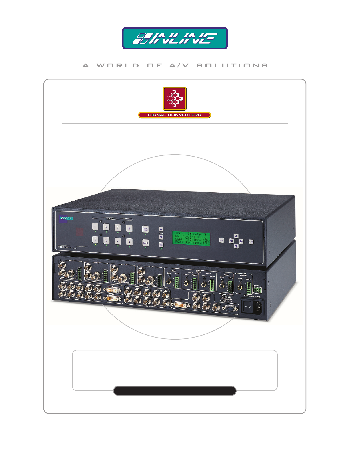
IN1408 VIDEO / DVI SCALER
WITH 8 INPUT SWITCHER
IN1408
OPERATION MANUAL
Page 2
Installation and Safety Instructions
For Models without a Power Switch:
The socket outlet shall be installed near the equipment and shall be accessible.
For all Models:
No serviceable parts inside the unit. Refer service to a qualified technician.
For Models with Internal or External Fuses:
For continued protection against fire hazard, replace only with same type and rating of fuse.
Instructions d’installation et de sécurité
Pour les modèles sans interrupteur de courant:
La prise de courant d’alimentation sera installé près de l’équipement et sera accessible.
Pour tout les modèles:
Pas de composants à entretenir à l’intérieur. Confiez toute réparation à un technicien qualifié.
Pour les modèles équipés de fusibles internes ou externes:
Afin d’éviter tout danger d’incendie, ne remplacer qu’avec le même type et la même valeur de fusible.
Installations- und Sicherheitshinweise
Für Geräte ohne Netzschalter:
Die Netzsteckdose soll in der Nähe des Gerätes installiert und frei zugänglich sein.
Für alle Geräte:
Keine Wartung innerhalb des Gerätes notwendig. Reparaturen nur durch einen Fachmann!
Für Geräte mit interner oder externer Sicherung:
Für dauernden Schutz gegen Feuergefahr darf die Sicherung nur gegen eine andere gleichen Typs und gleicher Nennleistung
ausgewechselt werden.
Instalacion E Instrucciones de Seguridad
Modelos Sin Interruptor:
Para Todos Los Modelos:
Modelos con Fusibles Internos o Externos:
La conexión debe ser instalada cerca del equipo y debe ser accesible.
Dentro de la unidad , no hay partes para reparar. Llame un tecnico calificado.
Para prevenir un incendio, reemplace solo con el mismo tipo de fusible.
CE COMPLIANCE
All products exported to Europe by Inline, Inc. after January 1, 1997 have been tested and found to
comply with EU Council Directive 89/336/EEC. These devices conform to the following
standards:
EN50081-1 (1991), EN55022 (1987)
EN50082-1 (1992 and 1994), EN60950-92
Shielded interconnect cables must be employed with this equipment to ensure compliance with
the pertinent Electromagnetic Interference (EMI) and Electromag netic Compatibility (EMC)
standards governing this device.
FCC COMPLIANCE
This device has been tested and found to comply with the limits for a Class A digital device,
pursuant to Part 15 of the FCC rules. These limits are designed to provide against harmful
interference when equipment is operated in a commercial environment. This equipment generates,
uses and can radiate radio frequency energy and, if not installed and used in accordance with th e
instruction manual, may cause harmful interference to radio communications. Operation of
equipment in a residential area is likely to cause harmful interference, in which case the user will be
required to correct the interference at their own expense.
Page 3

Table of Contents
Product Overview...........................................................................................................................2
Description................................................................................................................................... 2
Product Features...........................................................................................................................2
Compatibility..................................................................................................................................4
Input .............................................................................................................................................4
Output...........................................................................................................................................4
Installation......................................................................................................................................5
IN1408 Application Diagram.......................................................................................................8
IN1408 Rear Panel Connectors..................................................................................................10
Operation......................................................................................................................................11
Front Panel Controls...................................................................................................................11
IN1408 On Screen Display Menu System .................................................................................12
On Screen Menu......................................................................................................................... 13
Menu Commands.........................................................................................................................13
Video Menu................................................................................................................................13
Audio Menu................................................................................................................................16
Input Menu.................................................................................................................................17
Output Menu ..............................................................................................................................21
Advanced Menu.........................................................................................................................23
Choosing the Optimal Resolution and Refresh Rate................................................................25
CRT Displays - Selecting the Golden Resolution......................................................................25
CRT Displays - Selecting the Optimal Refresh Rate .................................................................25
Fixed Pixel Displays - Selecting the Optimal Resolution and Refresh Rate .............................26
Advanced Operation....................................................................................................................27
Pass-Through RGB Video..........................................................................................................27
Output RGB Connectors............................................................................................................27
Output Modes............................................................................................................................. 27
Default Power Buttons............................................................................................................... 28
Output Positioning......................................................................................................................28
Advanced Input Settings..............................................................................................................29
Remote Operation........................................................................................................................ 36
RS-232 Control ..........................................................................................................................36
IN1408 Serial Commands..........................................................................................................37
IR Remote Control......................................................................................................................41
Specifications................................................................................................................................42
Troubleshooting............................................................................................................................44
Product Dimensions.....................................................................................................................49
Warranty.......................................................................................................................................50
1
IN1408 Operation Manual - V1.4 3/21/02 12:32 PM © 2002 - INLINE, Inc.
Page 4

2
Product Overview
DESCRIPTION
IN1408 is the first video and RGB scaler offering DVI digital video inputs and can accept
virtually any popular video signal format. The IN1408 Video/DVI Scaler combines superb video
scaling for video, RGB computer video and DVI digital video signals with 8 Input A/V switching
capability. The IN1408 is a powerful system integration tool that makes it easy to connect a
variety of analog and TMDS digital (DVI / DFP) signal sources to data, presentation and HDTV
displays with analog or DVI inputs.
PRODUCT FEATURES
Sophisticated Motion Compensation Circuitry — Detects the original source material and
selects the optimal formula to eliminate motion artifacts. The scaler automatically switches to
adaptive frame mode (inverse 3:2 pulldown) with film-originated video sources.
Advanced Quad Standard Video Decoding - A high quality video decoder in the IN1408
provides accurate video decoding of composite video and S-Video signals in the NTSC, PAL,
SECAM and NTSC 4.43 video standards.
Advanced RGB Scaling - The IN1408 also provides superb up-scaling and refresh rate changing
for 640 x 480, 800 x 600 and 1024 x 768 resolution RGB video signals, making it an excellent
companion for LCD and DLP display devices that have marginal, on-board video scaling
capability.
DVI Input/Output – provides a direct digital connection for projectors, plasma panels and flat
panel displays with DVI/DFP inputs.
Large LCD Status Display – that is conveniently embedded in the IN1408 front panel offers an
easily viewable display of the system menu and settings.
Flexible Control Options – allow the user to control all the settings using the large LCD Display
or On-Screen Menu. All functions can also be controlled using the front panel controls, RS-232
serial commands or the optional CTL120 IR remote control.
Selectable Output Resolution - The IN1408 provides a progressive scan output signal at standard
resolutions and refresh rates, ensuring optimal compatibility and exceptional image quality with a
wide range of CRT, LCD, DMD, LCOS, and Plasma display devices.
Selectable Refresh Rate – allows the IN1408 to display a remarkably solid, flicker-free image
when using CRT monitors and projectors, the IN1408 output vertical refresh rate is adjustable
from 60 Hz to 120 Hz.
8-Input Video / Audio Switcher - The IN1408 provides multiple inputs and flexible switching
capability to accommodate a variety of applications. Stereo audio-follow-video switching is
provided for all eight inputs.
© 2002 - INLINE, Inc. IN1408 Operation Manual - V1.4 3/21/02 12:32 PM
Page 5

3
Digital Freeze Frame - provides a high quality still image for applications that require close
examination of a specific video frame.
Video Blank Button - allows the video image to be suppressed, outputting a solid black signal.
On Screen Menus - provide easy control of video adjustments including hue, color, contrast,
brightness, gamma, sharpness, image size, image position and edge blanking. Individual image
settings can be optimized and stored for each input.
Image Size, Position and Edge Blanking Controls – allows for easy precise fitting of the active
video image to the display area and provide for multiple aspect ratios by using individual
horizontal and vertical image adjustments.
Comprehensive Aspect Ratio Controls are provided for 4:3, letterbox, and anamorphically
enhanced signal sources. The Anamorphic mode provides vertical image squeezing and lets
users take full advantage of the superior image quality offered on anamorphically enhanced
DVDs.
Advanced Input Adjustment Controls - are provided to optimize the unit when used with nonstandard input signals. Input signal adjustments include: Total Pixels, Active Pixels, Active
Lines, Horizontal and Vertical Blanking, Phase and Scan Type.
Blue Screen Feature - provides a full screen blue image that acts as a test signal and is ideal for
setting up the output resolution, refresh rate, position settings, and to verify connection to the
output display device.
128 User Memories – stores all video, audio and input parameters to allow the unit to be
optimized for a large number of sources and gives the capability to recall those settings quickly.
RS-232 Serial Control - is provided for all scaler functions including input selections, image
adjustments and output settings.
Two Analog Video Outputs — Output 1 (15-Pin HD) can be set for RGBHV, RGBS, RGsB
signal format and is ideal for connecting to displays with RGB analog inputs. Output 2 (5 BNCs)
can be set for RGBHV / RGBS / RGsB or component video format, letting you connect to HDTV
displays and other devices that accept progressive component video input signals.
Rack Mountable - The IN1408 can be mounted in a 2U rack space using the MTR102 rack ears
(provided).
Stereo Audio Switching – capability for balanced and unbalanced audio signals with volume
control and mute.
Digital Audio Switching – The IN1408 is equipped with four digital audio inputs that accept
signals from computer sound cards with SPDIF digital outputs and DVD players with coaxial
digital audio outputs.
IN1408 Operation Manual - V1.4 3/21/02 12:32 PM © 2002 - INLINE, Inc.
Page 6

4
Compatibility
VIDEO INPUTS
The IN1408 Video Scaler accepts composite and S-Video signals in the NTSC, PAL, SECAM
and NTSC 4.43 video standards on all eight inputs. Inputs 5 - 8 are universal inputs that also
accept component video, progressive component video, RGBHV, RGBS, RGsB or computer pass
through. Inputs 5&6 have the added feature of accepting TMDS (single link ) dig ital v ideo sig nals
from computers with DVI or DFP digital video ports. When inputs 5 - 8 are set for passive mode,
they are compatible with virtually any signal format at any resolution and refresh rate.
AUDIO INPUTS
Analog Audio Signals
Inputs 1 - 8 include a 5-pin captive screw terminal for analog audio input. All eight analog stereo
audio inputs are compatible with balanced and unbalanced line level signals from a VCR, DVD
player, computer audio card, or any other audio device that delivers a stereo line level signal.
Digital Audio Signals
Inputs 5-8 are equipped to accept digital audio signals from DVD players with coaxial digital
outputs, computer sound cards with SPDIF digital audio outputs and other devices that feature
similar digital audio output signals. The selected digital audio input signal is routed passively to
the digital audio output with no signal processing.
VIDEO OUTPUTS
Resolutions and Refresh Rates
The IN1408 features selectable output resolutions from 640 x 480 up to 1365 x 1024 to match the
optimum or native resolution of virtually any display device. The unit provides a progressive scan
output signal at standard resolutions and refresh rates, ensuring optimal compatibility and
exceptional image quality with a wide range of CRT, LCD, DMD, D-ILA, and Plasma display
devices.
The output refresh rate is also selectable as desired. When used with LCD or DMD displays, the
60 Hz output setting is recommended. Higher output refresh rates may be selected for use on
CRT type displays in order to reduce flicker and provide enhanced ergonomics.
The IN1408 provides three video outputs: a DVI Digital Video connector, 5 BNC connectors
(RGB or component format), a 15-Pin HD (VGA) connector. Since the three sources are active
simultaneously, the IN1408 can directly drive three separate display devices. The output signal
format can be set to Component, RGBHV, RGBS or RGsB as required.
AUDIO OUTPUTS
Analog Stereo Audio
The analog stereo audio output provides a balanced or unbalanced line level output signal (see
page 5 for output wiring diagram). This output can drive any line level compatible audio unit, or
a local device such as powered speakers. The output level is adjustable using the volume control.
Digital Audio
The digital audio output provides a digital signal that is compatible with receivers and decoders
that feature coaxial digital audio inputs.
© 2002 - INLINE, Inc. IN1408 Operation Manual - V1.4 3/21/02 12:32 PM
Page 7
5
)RU%DODQFHG6WHUHR$XGLR2XWSXW
Installation
This section offers step-by-step instructions for installing the IN1408 Video Scaler. An
application diagram showing typical connections is provided on the page 8.
Á Note Prior to initiating the installation procedure, ensure that the power switch is in the
off mode on the IN1408 and there is no power supply cord connection to the unit.
1.) Place / install the IN1408 at the desired location. Make sure that the unit is seated on a
flat surface or is securely installed in a standard 19” equipment rack using the MTR102
rack ears (provided). The IN1408 is exactly 2U high without
will be located in the space directly below the scaler, the rubber feet on the bottom of the
unit must be removed before mounting it in the equipment rack.
2.) The IN1408 features a DVI video output, a 5-BNC video output and a 15-Pin HD video
output for easy connections to a variety of display devices:
• Digital display devices can be connected directly to the IN1408 DVI output. If the
video source features a DFP connector, use the appropriate IN9700 Series cable,
DFP / DVI Patch Cable or DFP / DVI adapter (a complete list of available INLINE
digital video cables and adapters can be found on page 9).
• Display devices that feature BNC input connectors can be connected directly to the
IN1408 BNC video output using three, four or five BNC cables (for RGsB, RGBS
or RGBHV, respectively) or a multi-conductor RGBHV, RGBS or RGB cable. The
INLINE IN7000 / IN7200 / IN7300 Series cables are well suited for this purpose
(see the RGB Input / Output Installation Cables table on page 42). While making
connections, take care to insure that the red output is connected to the red input,
green output is connected to the green input, etc.
• Display devices with a 15-pin HD input can be connected directly to the IN1408 15-
Pin HD output port using a standard VGA cable. INLINE’s IN8000 Series flexible
VGA cables offer exceptional performance and are available in a variety of lengths.
Á Note: Since all three outputs are active simultaneously, the IN1408 can directly drive three
separate display devices.
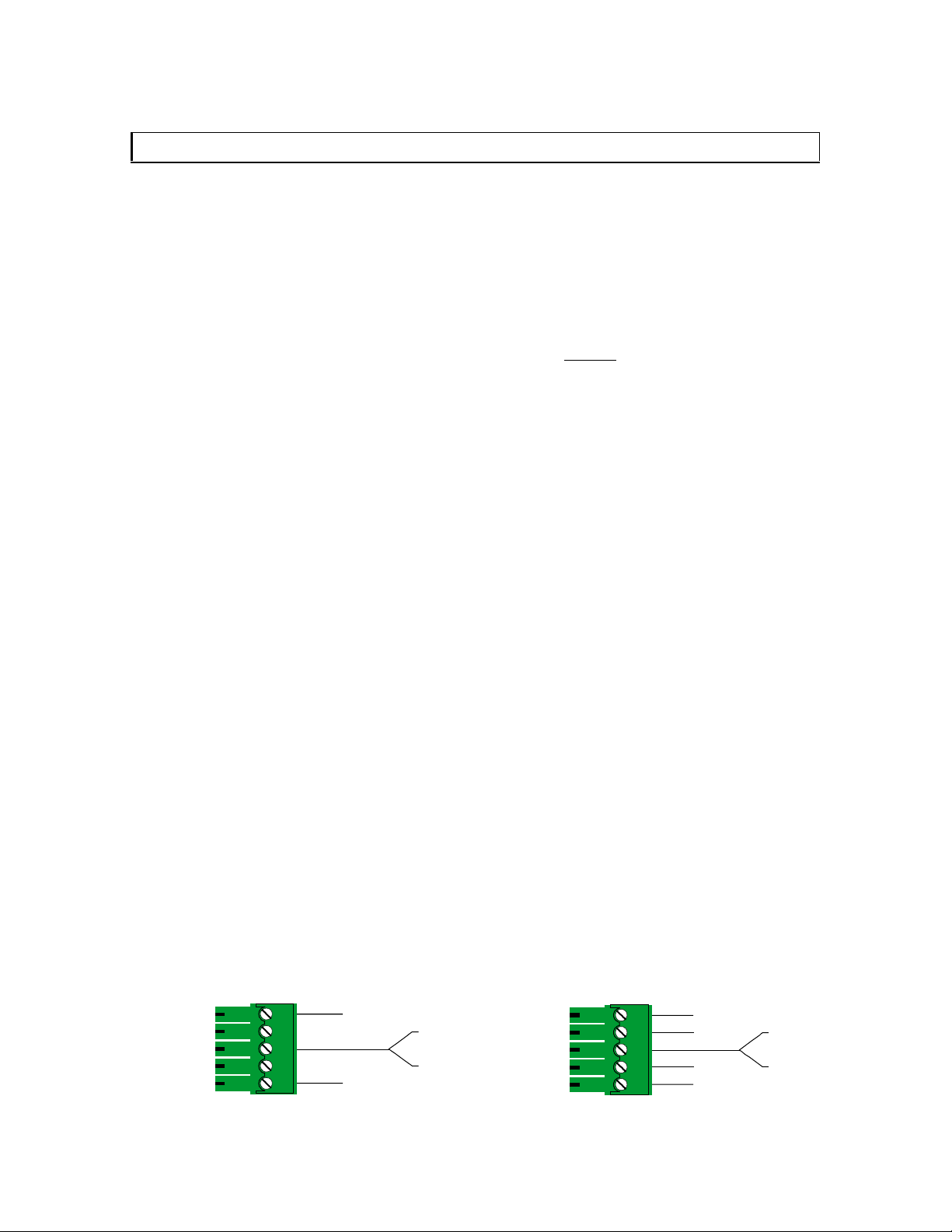
3.) Connect the IN1408 analog stereo audio output (5-pin captive screw terminal) to the audio
system’s line level input (mixer, amplifier, powered speakers, etc.). The output can be set for
balanced or unbalanced output signal as required by wiring the output appropriately (see
wiring diagram below). The analog audio output connector will accept stranded or solid
cables from 20 - 26 AWG.
)RU8QEDODQFHG6WHUHR$XGLR2XWSXW
the feet. If other equipment
IN1408 Operation Manual - V1.4 3/21/02 12:32 PM © 2002 - INLINE, Inc.
5LJKW
/HIW
5LJKW*URXQG
/HIW*URXQG
5LJKW
5LJKW
/HIW
/HIW
5LJKW*URXQG
/HIW*URXQG
Page 8
6
4.) Connect the IN1408 digital audio output (RCA female) to a compatible digital audio decoder
such as a receiver or digital audio processor. Use a 75 ohm cable to make the connection
between the IN1408 digital audio output and the sound system’s coaxial digital audio input.
5.) Connect the video / computer video source(s) to the appropriate IN1408 input
connectors. All eight inputs can accept either a composite video signal or an S-Video
signal. Inputs 5 - 8 are universal inputs that also accept interlaced component video,
progressive component video, RGBHV, RGBS, or RGsB video signals. For more details,
see Video Signal Input Connection Guide for Inputs 5 - 8 on page 7.
• Composite video sources with BNC output connectors can be connected using an
IN7200-1 Series high-resolution single coax cable. Devices with an RCA output
connector can be connected using an IN9101 BNC to RCA adapter cable.
• S-Video Sources may be connected using an IN9098 4-Pin Mini DIN Male to 2-BNC Male
adapter cable (6’ long).
Key Concept
On Inputs 1 through 4, Video input signals must only be connected to
either the composite video or the S-video connector on any one input.
DO NOT connect composite video and S-Video signals simultaneously
on the same input!
• Component video sources and Progressive component video sources may be
connected to Input 5, 6, 7 or 8 using an IN9101 RCA to BNC adapter cable or an
IN7300-3 Series 3-BNC cable. Ensure that the component video signals are connected
to the correct connectors.
RGsB / RGBS / RGBHV Video Signals from video and computer video sources can be
•
connected to Input 5, 6, 7 or 8 by using three, four or five BNC cables or a multiconductor RGBHV, RGBS or RGB "snake". The IN7000 / IN7200 / IN7300 Series
cables are well suited for this purpose (see RGB Input / Output Installation Cables on
page 42). While making connections, ensure that the red output is connected to the red
input, green output to the green input, etc.
• Digital Video sources can be connected to the DVI ports on Inputs 5 and 6.
Video Signal Connection Guide for Input s 5 - 8
When making connections to inputs 5, 6, 7 or 8, take care to connect each signal component to
the correct BNC connectors as indicated in the table below:
Signal Type
Red
BNC
Green
BNC
Blue
BNC
H / C
Sync
V Sync
BNC
BNC
Composite Video
S-Video
Component - Interlaced
Component - Progressive
RGsB
RGBS
RGBHV
C Y
R-Y Y B-Y
Cr Y Cb
Pr Y Pb
R Gs B
R G B S
R G B H V
C
© 2002 - INLINE, Inc. IN1408 Operation Manual - V1.4 3/21/02 12:32 PM
Page 9
7
5LJKW
5LJKW
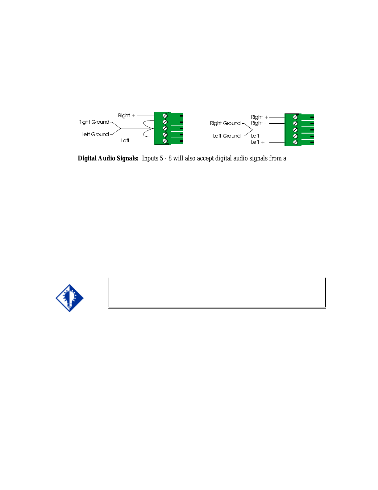
6.) Connect the audio signals to the appropriate inputs:
Analog Audio Signals: All eight Inputs will accept balanced or unbalanced stereo audio
signals. Connect the audio signals to the 5-pin captive screw connectors according to the
wiring diagram below:
)RU%DODQFHG6WHUHR$XGLR,QSXW)RU8QEDODQFHG6WHUHR$XGLR,QSXW
5LJKW
5LJKW*URXQG
5LJKW*URXQG
/HIW*URXQG
/HIW
/HIW*URXQG
/HIW
/HIW
Digital Audio Signals: Inputs 5 - 8 will also accept digital audio signals from a DVD player,
computer with a SPDIF digital audio output or other devices with a coaxial digital audio
output. Connect these digital audio signals to the Digital Audio RCA connectors.
7.)
If desired, connect a control system, computer or other serial command source to the
RS-232 remote connector. For more information about serial control of the IN1408, see
the Remote Operations Section on page 36.
8.)
Connect power to the IN1408 using the IN9230 IEC power cable (included).
9.) Turn on the video sources, the IN1408, the data display device(s) and the audio output
equipment (if applicable).
10.) Using the front panel controls or RS-232 commands, adjust and store the parameters for each
input source.
Key Concept
To ensure proper operation, it is critical that you set each input to match the
format of the signal connected to that input (i.e. composite, S-video,
componenet, RGBHV, etc.) See Signal Format under the INPUT MENU
section on page 17 for details.
11.) Set the output resolution and refresh rate to match your display device / installation
requirement. Refer to the Output Menu Section on page 21. For more information on
selecting an appropriate resolution / refresh rate, see Choosing the Optimal Resolution and
Refresh Rate on page 25.
12.) The default output format for the BNC connectors is RGBHV. If you need a Progressive
Component video output signal, use the BNC Output menu selection to set the format as
required (see page 22).
IN1408 Operation Manual - V1.4 3/21/02 12:32 PM © 2002 - INLINE, Inc.
Page 10
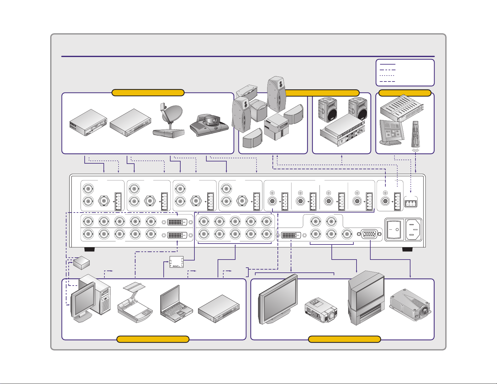
IN1408 VIDEO / DVI SCALER
APPLICATION DIAGRAM
= Analog Video
= DVI Video
= Analog Audio
= Digital Audio
VHS VCR
Composite Video
Y
C
S-VIDEO COMPOSITE VIDEO
RGB
R-Y Y B-Y
R-Y Y B-Y
RGBH/C V
1x2 DVI
Distribution
Amplifier
INPUT 1
input devices
DVD Player
S-Video
INPUT 2 INPUT 3 INPUT 4
Y
AUDIO 1
+
C
R
–
+
L
–
S-VIDEO COMPOSITE VIDEO
INPUT 5
Digital
Audio 5
H/C V
DSS Receiver
S-Video
Y
AUDIO 2
+
C
R
–
+
L
–
Video Conferencing
S-VIDEO COMPOSITE VIDEO
DVI
S-Video
Y
AUDIO 3
+
C
R
–
+
L
–
RGB
R-Y Y B-Y
R-Y Y B-Y
RGBH/C
Digital
Audio 7
S-VIDEO
COMPOSITE VIDEO
INPUT 7
INPUT 8INPUT 6
Digital
Audio 8
AUDIO 4
+
R
–
+
L
–
H/C V
AUDIO 5
DIGITAL ANALOG
+
R
–
+
L
–
V
sound system
Digital
Surround
Sound
DVIDVI
AUDIO 6
DIGITAL ANALOG
+
R
–
+
L
–
Analog Stereo
AUDIO
INPUTS
DIGITAL ANALOG
VIDEO OUTPUTS
H
RGB
R-Y Y B-Y
AUDIO 7
AUDIO 8
DIGITAL ANALOG DIGITAL ANALOG
+
R
–
+
L
–
TECHNICAL SUPPORT:
(800) 882-7117
V
(714) 921-4100
www.inlineinc.com
MADE IN U.S.A.
+
R
–
+
L
–
control
Control System
AUDIO
OUTPUTS
+
R
–
+
L
–
90-260 VAC; 0.5A; 47-63 HZ
RS-232
TX RXGND
CTL120
Infrared
Remote
(optional)
To Infrared
Sensor on
Front Panel
Computer
with DVI Output
Document Camera
with DVI Output
Laptop DVD with Progressive
Component Video Output
Plasma Display
with DVI Input
Data Projector
with DVI Input
Progressive Component
input devices output devices
HDTV
Data
Projector
Page 11

9
INLINE Digital Video Cables and Adapters
IN9700 High Performance Digital Video Cables
IN9725-1: DFP Male to DFP Male, 25’
IN9735-1: DFP Male to DFP Male, 35’
IN9750-1: DFP Male to DFP Male, 50’
IN9775-1: DFP Male to DFP Male, 75’
IN9725-2: DFP Male to DVI Male, 25’
IN9735-2: DFP Male to DVI Male, 35’
IN9750-2: DFP Male to DVI Male, 50’
IN9775-2: DFP Male to DVI Male, 75’
IN9725-3: DVI Male to DVI Male, 25’
IN9735-3: DVI Male to DVI Male, 35’
IN9750-3: DVI Male to DVI Male, 50’
IN9775-3: DVI Male to DVI Male, 75’
DFP / DVI Digital Video Patch Cables
DFPM-DFPM-3:
DFPM-DFPM-6:
DFPM-DFPM-15:
DFPM-DVIM-3:
DFPM-DVIM-6:
DFPM-DVIM-15:
DVIM-DVIM-3:
DVIM-DVIM-6:
DVIM-DVIM-15:
DFP / DVI Adapters
IN9280: Digital Video Adapter, MDR20 Female to DVI Male
DFP Digital Video Cable, MDR20 Male to Male, 3’
DFP Digital Video Cable, MDR20 Male to Male, 6’
DFP Digital Video Cable, MDR20 Male to Male, 15’
DFP / DVI Digital Video Adapter Cable, MDR20 Male to DVI Male, 3’
DFP / DVI Digital Video Adapter Cable, MDR20 Male to DVI Male, 6’
DFP / DVI Digital Video Adapter Cable, MDR20 Male to DVI Male, 15’
DVI Digital Video Cable, DVI Male to Male, 3’
DVI Digital Video Cable, DVI Male to Male, 6’
DVI Digital Video Cable, DVI Male to Male, 15’
IN1408 Operation Manual - V1.4 3/21/02 12:32 PM © 2002 - INLINE, Inc.
Page 12
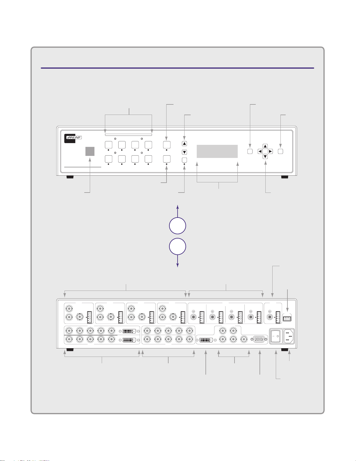
IN1408 VIDEO/DVI SCALER
CONNECTORS & CONTROLS
Rear
View
Front
View
90-260 VAC; 0.5A; 47-63 HZ
TECHNICAL SUPPORT:
(800) 882-7117
(714) 921-4100
www.inlineinc.com
MADE IN U.S.A.
INPUT 1
Y
C
S-VIDEO COMPOSITE VIDEO
AUDIO 1
+
–
+
–
INPUT 2 INPUT 3 INPUT 4
INPUT 7
AUDIO
INPUTS
VIDEO OUTPUTS
AUDIO
OUTPUTS
R
L
Y
C
S-VIDEO COMPOSITE VIDEO
AUDIO 2
+
–
+
–
R
L
Y
C
S-VIDEO COMPOSITE VIDEO
AUDIO 3
+
–
+
–
R
L
Y
C
S-VIDEO
RGB
R-Y Y B-Y
R-Y Y B-Y
H/C V
RGBH/C V
INPUT 5
INPUT 8INPUT 6
RGB
R-Y Y B-Y
R-Y Y B-Y
H/C V
RGBH/C V
COMPOSITE VIDEO
AUDIO 4
AUDIO 5
DIGITAL ANALOG
AUDIO 6
DIGITAL ANALOG
AUDIO 7
DIGITAL ANALOG
AUDIO 8
DIGITAL ANALOG DIGITAL ANALOG
+
–
+
–
R
L
+
–
+
–
R
L
+
–
+
–
R
H
DVIDVI
DVI
V
RGB
R-Y Y B-Y
L
+
–
+
–
R
L
+
–
+
–
R
L
+
–
+
–
R
L
TX RXGND
RS-232
IN1408
Vide o / DVI Scal er
MUTE
AUDIO
VOLUME
INPUT SELECT
2
6
1
5
3
748
BLANK
FREEZE
FRAME
ENTER
MENU
LCD Status Display
Input Select
Buttons
Blank Button
Infrared
Sensor
Mute Button
Volume Control
Menu Button
Enter Button
Freeze Frame
Menu Navigation/
Adjustment Controls
A/C Power
Connector
DVI
Output
RGB
Output
RGB/Component
Output
On / Off
Power Switch
Video/Audio Inputs 1-4
Video Inputs 5 & 6
Audio Inputs 5-8
Audio Outputs
(Digital/Analog)
Video Inputs 7 & 8
RS-232 Serial
Control Port
Input: Computer 3
DVI Digital Video
Out: 1280x1024 60Hz
RGB+Component+DVI
Page 13

11
Operation
This section focuses on operating the IN1408 using the front panel controls and commands. All
adjustments, set-up functions and switching operations can be performed through the front panel or
remotely via RS-232 serial commands or the optional IR remote control. Information on using the
optional CTL120 IR remote can be found on page 41.
FRONT PANEL CONTROLS
Input Select: Selects the audio and video source. The large buttons labeled INPUT 1, INPUT 2,
INPUT 3, INPUT 4 INPUT 5, INPUT 6, INPUT 7, and INPUT 8 are used to select the desired
input. After turning on the IN1408, press and release the desired INPUT SELECT Button. A green
LED will light underneath the button to indicate the selected input. The stereo audio signal associated
with the input will automatically be selected at the same time. All audio, video and input settings for
each input are stored internally (in memory) so the adjustment(s) will not have to be repeated after
they are optimized. To switch to another input, simply press and release another numbered INPUT
SELECT Button.
Á Note: When powered up, the scaler automatically returns to the last configuration, including
the last input selected.
The BLANK Button can be used at any time to show a blank screen on the display device. When
blank is engaged, the output setting goes to black but the sync signals continue, ensuring that the data
display device retains sync lock. Simply press and release the button to engage blanking (the green
LED underneath the button will illuminate), and press and release it again to disengage.
Á
Freeze Frame: Allows users to freeze the video signal and display a still image. Simply press and
release the button to engage the function (the green LED below the button will illuminate), then press
and release again to disengage.
Á Note: The freeze button has no effect on inputs 5 - 8 when they are configured as passive
Volume: The volume buttons are used to regulate the level of the audio signals routed through the
scaler. Use the ¾ / ¿ volume buttons to increase / decrease the audio level for the current input.
Press and release a button to raise / lower the volume level by one step, or press and hold a button to
change the level continuously. Digital sound is a passive signal and can only be muted.
Á Note: The IN1408 saves the volume levels for each input automatically.
Audio Mute: Mutes the audio for the selected input. Press the button to engage (the green LED
below the button will illuminate), and press again to disengage.
Menu Buttons: The remaining buttons on the front panel (MENU, ¾, ¿, ½, ¼ and ENTER) are
used to access and adjust the on-screen display menu. An illustration of the On Screen Display Menu
System is provided on the next page.
Note: The blank button has no effect on inputs 5 - 8 when they are configured as passive
inputs.
inputs
IN1408 Operation Manual - V1.4 3/21/02 12:32 PM © 2002 - INLINE, Inc.
Page 14
12
IN1408 ON SCREEN DISPLAY
MENU SYSTEM
Video5
Brightness
Contrast
Color Saturation
RGB Gain
Hue
Sharpness
Gamma
Noise Filter
1, 2
3, 4
1, 2
1, 2, 3
1, 2
1, 2
Comb/Trap1
Reset Video
RGB Gain
3, 4
Red
Green
Blue
Comb/Trap1
Comb Filter
Trap Filter
Both Off
Reset Video
Yes
No
Notes:
In Executive Mode the available menu items are restricted and only the
menu items shown in bold are available.
1. Composite Video
2. S-Video
3. Interlaced Component and Interlaced RGB
4. Progressive Component and Progressive RGB
5. Not available for DVI inputs
6. Inputs 5 and 6
7. Inputs 5 through 8
8. Refresh rates available depend on the current resolution
Audio
Bass
Treble
Balance
Reset Audio
Reset Audio
Yes
No
Input #
Composite
S-Video
Component Inter7
Component Prog7
RGBS Interlaced7
RGB Progressive7
DVI Digital6
RGB Passive7
Active Area
Active Pixels
Active Lines
Blanking
H-Blanking
V-Blanking
Scan Type
Interlaced
Swap Fields
Invert Sync
Input Mode
Auto Detect
Lockout Changes
User Defined
Redetect Now
Main Menu
Video5
Audio
Input
Output
Advanced
Input
Signal Format
Aspect Ratio
Horiz Tracking
Fine Phase
Advanced
Reset Input
Signal Format
Input 1
Input 2
Input 3
Input 4
Input 5
Input 6
Input 7
Input 8
Aspect Ratio
Standard
Anamorphic
Wide Screen
Wider Screen
Expand
HorizTracking
Very Fast
Fast
Normal
Slow
Advanced
Active Area
Blanking
Total Pixels
Scan Type
Input Mode4
Reset Input
Yes
No
Output
Resolution
Refresh Rate8
Size
Position
Sync Format
Blue Screen
BNC Output
1,2
3, 4
RGB Gain
Reset Output
1, 2
Resolution
640 x 480
800 x 600
852 x 480
1024 x 768
1152 x 864
1280 x 720
1280 x 768
1280 x 1024
1365 x 765
1365 x 1024
Refresh Rate8
56 Hz
60 Hz
65 Hz
72 Hz
75 Hz
1,2
3, 4
3, 4
85 Hz
96 Hz
100 Hz
120 Hz
Size
H-Size
V-Size
Position
H–position
V-position
Sync Format
RGBHV--
RGBHV++
RGBS
RGBS w/Serr
RGsB
RGsB w/Serr
Blue Screen
On
Off
BNC Output
Component
RGB
Reset Output
Yes
No
Advanced
Executive Mode
On Screen Menu
Input Labels
User Memory
Baud Rate
Delimiters
Reset RS-232
IR Code Format
Factory Reset
System Info
Executive Mode
On / Off
On Screen Menu
On / Off
Input Labels
Off
On
Momentary
Reset Label
User Memory
Save
Recall
Reset
Baud Rate
1200
2400
4800
9600
19200
38400
57600
Delimiters
Parenthesis
Brackets
Braces
Slashes
Less & Greater
Signs ! #
Reset RS-242
Yes / No
IR Code Format
Code Bank A (001)
Code Bank B (028)
Factory Reset
Yes
No
System Info
Input #
Signal Format
Input Horiz
Input Vert.
Output Size
Output Horiz.
Output Vert.
Sync Format
Version
IN1408 Operation Manual - V1.4 3/21/02 12:32 PM © 2002 - INLINE, Inc.
Page 15
13
ON SCREEN MENU
To access the main menu, press the MENU or ENTER Button. Use the arrow buttons to maneuver
around within the menu display. Press ENTER to select and save a command, or press MENU to exit
(out of the menu). All audio, video, input and output settings for each input and each output mode are
stored internally (in memory) so the adjustments will not have to be repeated after they are optimized.
The MAIN MENU commands and their functions are:
VIDEO - Changes input signal video parameters
AUDIO - Changes input signal audio parameters
INPUT - Changes input signal parameters
OUTPUT - Changes output signal parameters
ADVANCED - Displays advanced options
Menu Commands
Save It or Lose It!
After you have optimized a setting, save it by pressing the ENTER BUTTON.
It is critical
another menu function, otherwise your new adjustment will be lost.
VIDEO MENU
The IN1408 allows users to manually adjust the brightness, contrast, RGB gain, color, hue, sharpness,
gamma, noise filter, and comb / trap filter settings.
To access the video adjustment menu via the front panel control buttons, press the desired INPUT
SELECT Button, press MENU, press the ¿ or ¾ button (if necessary) to reach the video menu, then
press ENTER. Use the ¾ and ¿ buttons and the ENTER key to select the setting you wish to adjust.
After selecting a setting, use the ½ and ¼ buttons to make the adjustments. Press and release a button
to move by one step in either direction. Press and hold a button to move continuously through the
adjustment range. Once you’ve optimized the setting for the current input, press ENTER to save.
Key Concept
If these settings seem confusing, we recommend that you experiment with the
MENU, ¾, ¿, ½, ¼ and ENTER Buttons until you familiarize yourself with
the IN1408 front panel control operations. It’s a good idea to get comfortable
using these buttons to navigate through the on-screen menu system before
moving on to other sections of this manual. If you get lost, enter unfamiliar
territory or are afraid of making an improper selection, pressing the MENU
button allows you to leave the menu system safely without making any changes.
We also recommend that, unless you’re a qualified audiovisual technician, you
should avoid entering the Advanced Menu
that you save the setting before proceeding to another input or
IN1408 Operation Manual - V1.4 3/21/02 12:32 PM © 2002 - INLINE, Inc.
Page 16

14
The following video adjustment parameters can be controlled via the on-screen menu system which
can be accessed using the front panel buttons or the optional CTL120 IR remote control. See page 41
for information on using the CTL120 IR remote.
Á Note:
Video adjustments do not affect inputs configured for RGB passive.
Brightness Setting: Adjusts the input signal brightness.
Range: 0 to 255 Factory Default Setting: 128
Operation: Press ½ button to increase the brightness.
Press ¼ button to decrease the brightness.
Contrast: Adjusts the difference between the input signal’s brightest and darkest settings. At the
minimum setting the entire picture is displayed at about the same brightness (very grayish). At the
maximum setting there is a great difference between the darkest and lightest parts of the screen.
Range: 0 to 255 Factory Default Setting: 128
Operation: Press ½ button to increase the contrast.
Press ¼ button to decrease the contrast.
Color Saturation: Adjusts the color saturation of the picture over a wide range. Setting this control
to 0 will remove most of the color. This control is only available for composite and S-Video signals.
Range: 0 to 255 Factory Default Setting: 128
Operation: Press ½ button to increase the color.
Press ¼ button to decrease the color.
RGB Gain: Changes the input signal gain (contrast) for each individual color. This control is only
available for component video, RGBHV, RGBS and RGsB signal formats. Red, green and blue
controls are available.
Range: 0 to 255 Factory Default Setting: 128
Operation: Press ½ button to increase the Red, Green or Blue Gain.
Press ¼ button to decrease the Red, Green or Blue Gain.
Hue (NTSC Signals Only): Adjusts the picture’s color towards red or green. This control is only
available for composite and S-Video signals.
Range: 0 to 255 Factory Default Setting: 128
Operation: Press ½ button to increase the green.
Press ¼ button to increase the red.
© 2002 - INLINE, Inc. IN1408 Operation Manual - V1.4 3/21/02 12:32 PM
Page 17

15
Sharpness: Uses variable filtering to affect input picture detail and definition. This control is only
available for composite, S-Video, component interlaced and RGBS interlaced signals.
Range: 0 to 8 Factory Default Setting: 3
Operation: Press ½ button to increase the sharpness.
Press ¼ button to decrease the sharpness.
Á Note:
Increasing the sharpness setting gives the visual effect that the noise filter setting is
decreasing. Although the sharpness and noise filter settings seem to offset each other, they
are actually two different adjustments that affect two different sets of circuitry. Operators
should adjust both settings until optimal picture quality is achieved.
Gamma: The 30 active gamma correction curves programmed into the IN1408 are used to
compensate for the non-linear response of many display devices. Before adjusting Gamma, the
brightness and contrast controls should be set at factory default positions. Once the proper gamma
setting has been achieved, the brightness and contrast settings should then be optimized to fine
tune the image. This control is only available for composite and S-Video signals only.
Range: 1 to 30 Factory Default Setting: 10*
Operation: Press ½ button to step to higher numbered gamma curves.
Press ¼ button to step to lower numbered gamma curves.
9600 The factory default setting of 10 corresponds to a gamma correction curve of 1.0
Noise Filter: Changes the input signal noise filter.
This control is only available for composite and
S-Video signals.
Range: 0 to 47 Factory Default Setting: 9
Operation: Press ½ button to increase noise filter.
Press ¼ button to decrease noise filter.
Á Note:
Increasing the noise filter setting gives the effect that the picture sharpness setting is
decreasing. Decreasing the noise filter will effectively add more image detail. Review the
Sharpness setting section on the previous page.
Comb/Trap Filter: Selects the comb filter, trap filter or turns both off.
This control is only available
for composite signals.
The comb filter electronically provides excellent Luma / Chroma separation (separates the
color from the picture signal). This greatly reduces cross-color interference and hanging dots
while maintaining image bandwidth and detail (applies to composite, S-Video and
Component A signal formats only).
The trap filter extracts luminance from the picture. Generally speaking, the trap filter is
usually the preferred setting when running signals from a VCR (as composite video). You
may wish to compare both settings to determine which is best for your application.
Reset Video Settings: Resets all video settings to factory default (for current input only).
IN1408 Operation Manual - V1.4 3/21/02 12:32 PM © 2002 - INLINE, Inc.
Page 18

16
AUDIO MENU
The IN1408 allows users to manually adjust the bass, treble and balance settings.
Á Note:
To access the audio adjustment menu via the front panel control buttons, press the desired INPUT
SELECT Button, press MENU, press the ¿ or ¾ button (if necessary) to reach the audio menu, then
press ENTER. Use the ¾ and ¿ buttons and the ENTER key to select the setting you wish to adjust.
After selecting a setting, use the ½ and ¼ buttons to make the adjustments. Press and release a button
to move by one step in either direction. Press and hold a button to move continuously through the
adjustment range. Once you’ve optimized the setting for the current input, press ENTER to save.
The following audio adjustment parameters can be controlled via the on-screen menu system which
can be accessed using the IN1408 front panel buttons or the optional CTL120 IR remote control. See
page 41 for information on using the CTL120 IR remote.
Á Note:
Bass: Increases / decreases the lower frequencies of the audio signal.
Press ¼ button to decrease the bass frequencies.
Treble: Increases / decreases the higher frequencies of the audio signal.
Press ¼ button to decrease the treble frequencies.
Balance: Shifts the audio balance toward the right or left audio channels.
Press ¼ button to move the balance toward the left channel.
Reset Audio Settings: Resets all audio settings to factory default (for current input only
The only control available for digital audio signals is MUTE.
While on-screen menus are not displayed for Inputs 5 - 8 when set for RGB passive
mode, all audio functions are still available for these inputs
.
Range: 6 to 27 Factory Default Setting: 16 (0.0dB)
Operation: Press ½ button to increase the bass frequencies.
Range: 8 to 25 Factory Default Setting: 16 (0.0dB)
Operation: Press ½ button to increase the treble frequencies.
Range: 0 to 31 Factory Default Setting: 16
Operation: Press ½ button to move the balance toward the right channel.
)
© 2002 - INLINE, Inc. IN1408 Operation Manual - V1.4 3/21/02 12:32 PM
Page 19

17
INPUT MENU
Key Concept
To access the input menu via the front panel control buttons, press the desired INPUT SELECT
Button, press MENU, press the ¿ or ¾ button (if necessary) to reach the input menu, then press
ENTER. Use the ¾ and ¿ buttons and the ENTER key to select the setting you wish to adjust.
Once you’ve optimized the setting for the current input, press ENTER to save.
Signal Format: Use this control to select the signal format for each input. Inputs 1 - 8 can accept
either composite or S-Video signals. Inputs 5 - 8 also accept component, progressive component,
RGBHV, RGBS, RGsB or RGB Passive. Inputs 5&6 are the only inputs to accept DVI / TMDS
digital video signals. On Inputs 1 - 4, the composite and S-Video connections are internally wired
together; therefore, either composite or S-Video can be connected to each input, but not both at the
same time. Refer to the Installation Section on page 7 for the specific connections for each signal
format.
Signal Formats available are:
• Composite
• S-Video
• Component Interlaced
(Sub-menu selects NTSC / PAL / SECAM format)
• Component Progressive
• RGBS Interlaced
• RGB Progressive
(Sub-menu selects RGBHV / RGBS / RGsB format)
• DVI Digital
• RGB Passive (Passive Switching with No Scaling or Controls Available)
Compatible with RGBHV, RGBS, RGsB, Component Video Progressive or Interlaced
Signals
To configure the inputs for a specific Signal Format:
• Press the ENTER or MENU Button to access the main menu.
• Highlight INPUT and press ENTER to access the input menu (use the ¾ and ¿ arrow
buttons to highlight the appropriate menu command).
• Highlight SIGNAL FORMAT and press ENTER to access the input selection menu.
• Highlight the input you want to configure and press ENTER to access the signal format
menu.
• Select the signal format for each individual input (use the ¾ and ¿ buttons to select the
desired signal format).
• Press ENTER to save the signal format into memory.
Hint: Adjust the IN1408 output settings first
. Adjust the resolution, refresh
rate, size, position and sync format, along with the display device settings,
to fit the video image on the screen (use the blue screen if necessary). Once
the IN1408 output settings and the display device settings have been
properly adjusted, the IN408 input settings and video adjustments may be
configured for each input signal.
IN1408 Operation Manual - V1.4 3/21/02 12:32 PM © 2002 - INLINE, Inc.
Page 20

18
Key Concept
It is critical that the signal format be selected properly for each input. If the
input is not properly configured to match the input signal, the scaler will not
function properly and will either display a distorted image or no image at all.
Using the on-screen menu, operators can set / change the input signal format
at any time, even when another input is active. For example: an operator
can configure the signal format for Input 1 while the display device is
presenting a signal that is passing through Input 3. This method is required
to deselect the RGB passive signal format, since the on-screen menu cannot
be seen while in this mode. These details are discussed in the Pass-Through
RGB Video Section on page 27.
Aspect Ratio – The aspect ratio controls can be used to vary the relative image width and height.
They can be used to accommodate various input signal aspect ratios as well as output device
aspect ratios. The output aspect ratio is selected by choosing the appropriate resolution in the
output menu (see Output Modes Section on page 27).
Standard: For Standard 1.33 input signals (sometimes referred to as full
screen).
Anamorphic: This setting provides vertical image squeezing to accommodate
anamorphically enhanced DVDs.
Wide Screen: For wide screen 1.78 input signals (letterbox).
Wider Screen: For wider screen 2.35 input signals (narrow letterbox).
Expand: Designed for wide screen (letterbox) signals viewed on 4:3 aspect
ratio displays. Expand mode zooms in on the center of the image
and crops the image vertically and horizontally so that the black
bars above and below the image are removed. In this mode, some
image is also lost on the right and left hand edges.
Most DVDs and VCRs put out a 4:3 signal. How this signal is filled with video determines its
aspect ratio. In the following examples, four different input aspect ratios are shown on the left as
they would be displayed in their native 4:3 format. The same signals are shown on the right as
they would appear on the output after scaling.
© 2002 - INLINE, Inc. IN1408 Operation Manual - V1.4 3/21/02 12:32 PM
Page 21

19
16:9 Display
4:3 Display
Example 1:
Aspect Ratio Setting: Standard
4:3 Display
Example 2:
Aspect Ratio Setting: Wide Screen
16:9 Display
IN1408 Operation Manual - V1.4 3/21/02 12:32 PM © 2002 - INLINE, Inc.
Page 22

20
Example 3:
4:3 Display
Aspect Ratio Setting: Anamorphic
16:9 Display
Example 4.
Aspect Ratio Setting: Expand
4:3 Display
© 2002 - INLINE, Inc. IN1408 Operation Manual - V1.4 3/21/02 12:32 PM
Page 23

21
Horizontal Tracking:
(Composite / S-Video Signals Only) This control adjusts horizontal sync
tracking to prevent image bending (hooking) along the top of the video image. Various settings
are available to compensate for different quality input signals:
Very Fast
For poor quality video signals, such as from a VCR.
Fast For normal quality video signals, such as from a TV.
Normal For good quality video signals, such as from a DVD player.
Slow For high quality video signals, such as broadcast video.
Fine Phase: Adjusts the amount of phase shift applied to the input signal. If video noise is
present in the image, the fine phase control may be effective in optimizing the image to remove
video noise due to input timing errors. Fine Phase is only available for Interlace Component,
Progressive Component, RGBHV, RGBS and RGsB signal formats.
Advanced: The Input menu also includes several adjustments under the Advanced settings
option. These adjustments are rarely needed for standard video signals and computer video
signals and are mainly designed to optimize the quality when inputting non-standard or
proprietary video signals. Most users should not adjust the Advanced Input settings. For
additional details on Advanced Input Settings, please see Advanced Input Settings Section on
page 29.
Reset Input: Resets all input settings to factory default (for the current input only
).
OUTPUT MENU
To access the output menu via the front panel control buttons, press MENU, press the ¿ or ¾
button (if necessary) to reach the output menu, then press ENTER. Use the ¾ and ¿ buttons
and the ENTER key to select the setting you wish to adjust. Once you’ve optimized the setting
for the current output, press ENTER to save.
Output Resolution: This control lets you select the appropriate resolution for your display
device. The available resolutions are listed on page 27. Because the IN1408 only scales up,
users must choose an output resolution that is greater than or equal to the input size. For instance,
you may not select 640 x 480 output with PAL input signals since PAL has more than 480 lines
of video.
Refresh Rate: Allows users to choose the optimal refresh rate for their display device.
Á Note: Not all resolution and refresh rate combinations are available. Refer to the chart on
page 27 for a chart of available resolutions / refresh rates.
Key Concept
Of all the settings on the IN1408, perhaps the most critical adjustments are
the output resolution and output refresh rates. Setting the scaler to match
the capabilities of your data display device will have an enormous impact
on the image quality. To achieve the optimum image on your display
device, refer to the instructions on pages 25 & 26.
IN1408 Operation Manual - V1.4 3/21/02 12:32 PM © 2002 - INLINE, Inc.
Page 24

22
Size: This adjusts the output horizontal and vertical size. It shrinks the size to a percentage of
the output resolution selected. The output size is automatically reset anytime a new input aspect
ratio is selected. This setting is useful to manually reduce the height of the output signal when an
anamorphic input signal is connected. The IN1408 only scales up; therefore, the output size
controls will stop at a certain point where the input and output resolution are equal.
Position: Shifts the output image Up / Down / Left / Right on the display device. Unlike input
blanking, the Position control does not crop the image or add blank borders. The output position
is automatically reset anytime a new input aspect ratio is selected. To quickly access the position
adjustment, simply press one of the front panel
¾ ¿ ¼ ½ buttons at any time when the on-screen
menu is not displayed. This immediately shifts the image in the appropriate direction. Press ENTER
to accept the new setting. If desired, t
he position control can also be accessed using the Position
on-screen menu item under Output menu.
Sync Format: Select an output signal format that is compatible with your display.
RGBHV--
RGB with negative horizontal and vertical sync (default)
RGBHV++ RGB with positive horizontal and vertical sync
RGBS RGB with composite sync (without serrations)
RGBS w/Serr RGB with composite sync (with serrations)
RGsB RGB with sync on green (without serrations)
RGsB w/Serr RGB with sync on green (with serrations)
Blue Screen: Available anytime (even when the input settings are incorrectly adjusted or the
input signal is missing entirely), the blue screen may be used as a test signal to adjust the output
settings (resolution, refresh rate, size, position and sync format) and verify the image on the
monitor. The video and input settings have no effect on the blue screen. Once the output settings
have been properly adjusted and verified on the monitor, the blue screen may be turned off to
adjust the video and input settings.
BNC Output: Use this menu item to select the color space format for the 5-BNC output.
The factory default is RGB color space (RGBHV, RGBS or RGsB). If you are connecting to an
HDTV display or other device that requires a component video signal, set this menu item to
Component. This adjustment does not affect the 15-Pin HD and DVI output, which always
output signals in the RGB color space.
RGB Gain: This is a global setting that can be adjusted to compensate for the color temperature
of the display device. This RGB gain setting only applies to composite video and S-video
signals.
Range: 0 to 255 Factory Default Setting: 128
Operation: Press ½ button to increase the Red, Green or Blue Gain.
Press ¼ button to decrease the Red, Green or Blue Gain.
Reset Output Settings: Resets all output settings to factory default.
© 2002 - INLINE, Inc. IN1408 Operation Manual - V1.4 3/21/02 12:32 PM
Page 25

23
ADVANCED MENU
To access the advanced menu via the front panel control buttons, press MENU, press the ¿ or ¾
button (if necessary) to reach the advanced menu, then press ENTER. Use the ¾ and ¿ buttons
and the ENTER key to select the setting you wish to adjust. Once you’ve optimized the setting,
press ENTER to save.
Executive Mode: This is a restricted operation mode that permits adjustments of common
controls but removes all menu items for advanced controls. Executive Mode is ideal for rental
applications, home theater installations and any other application where a non-technical users can
select inputs, adjust volume, and make video image quality adjustments, while advanced settings
like output resolution / refresh rate, RS-232 communication settings and other advanced
adjustments are disabled. When Executive Mode is enabled, all advanced function menu items
will now be missing from the on-screen and LCD menus, however, these functions are still
available through RS-232 serial commands.
To Enable or Disable Executive mode, use the menu item found under the advanced menu.
As shown in the menu tree on page 12, when Executive Mode is enabled only the items shown in
bold will be available.
On-Screen Menu: This menu item allows you to enable or disable the on-screen menus. It does
not affect the LCD status display, which is always functional.
Input Labels: Each input can display a label on the screen to indicate the name of the current
input. The factory default input labels read "Input x", with x being the number of the current
input. The IN1408 can also be programmed with custom input labels such as "VCR" , "Camera
5", or "DVD #2" or any other desired text to correspond with the name of the actual source
connected to each input. Use the input Select from the following label options:
• On: The labels remain on-screen and change each time a new input is selected.
• Off: The labels remain off and are not displayed.
• Momentary: The label is displayed for 3 seconds anytime a new input is selected.
• Reset: This resets the label to the factory default of “Input #.” This is beneficial if
the label was changed via user memory, or to reset the label if RS-232 control is no
longer available.
Á Note: The input label text is user definable via RS-232 commands. Refer to RS-232
Control Section on page 36 for more information.
Factory Reset: Returns all video, audio, input, output and RS-232 settings for all inputs to
factory default.
IN1408 Operation Manual - V1.4 3/21/02 12:32 PM © 2002 - INLINE, Inc.
Page 26

24
User Memory: The User Memories (from 5 to 128) store all video, audio and input parameters.
If a different input signal is applied to the IN1408, the User Memory can be recalled to return the
video, audio and input settings for that particular signal. Select from the following options:
• Save: This saves all of the video, audio and input parameters for the current input
into the selected memory.
• Recall: This recalls all of the video, audio and input parameters from the selected
memory into the current input.
• Reset: This resets all video, audio and input parameters for the selected memory
based on the current input mode.
Á Note:
Some parameters such as Active Area and Blanking are input mode dependent.
Before recalling a user memory that has not been previously saved, it is best to reset that
particular memory so it will be programmed for the current input mode
Baud Rate: Allows RS-232 remote users to select the baud rate that matches their remote
control device system.
Delimiters: Use the on screen menu to select the desired command code delim iters. I N LINE scalers
can be set to recognize six sets of leading and end codes when using an RS-232 remote:
parentheses ( ), brackets [ ], braces{ }, slashes \ /, less and greater than < >, and signs !#. If desired,
several INLINE products may be connected together on the same RS-232 serial control line with each
device set for a different delimiter pair. Each unit will only respond to codes sent with the
appropriate delimiters and will ignore all other codes.
Reset RS-232 Settings: Resets all RS-232 settings to factory default.
IR Code Format: This menu item selects the IR code format for the IN1408. This may be used
to select an alternative IR code format for installations where the IN1408 IR codes are conflicting
with other devices in the room. The factory default is code bank A and will work when the
optional CTL120 remote is set to code 001. The alternative code format is code bank B. If the
unit is set to Code Bank B, the CTL120 remote must be programmed to code 028 (see the
CTL120 operation manual for more information).
System Info: This is an informative display that shows a variety of information about the
currently selected input signal and scaler output settings on a single screen. The System Info
display may be useful for troubleshooting or to quickly verify various settings. The following
information is included in the System Info display:
• Input Source
• Input Horizontal Scan Rate
• If Input is Interlaced
• Output Horizontal Scan Rate
• Output Sync Format
• Input Signal Standard and Format
• Input Vertical Refresh Rate
• Output Resolution
• Output Vertical Refresh Rate
• Program Version Number
© 2002 - INLINE, Inc. IN1408 Operation Manual - V1.4 3/21/02 12:32 PM
Page 27

25
Choosing the Optimal Output Resolution and Refresh Rate
Of all the settings on the IN1408, perhaps the most critical adjustment is the output resolution and
output refresh rate. Every display device has an optimal or native resolution and an optimal
refresh rate. This will vary depending on the type of display technology, if the display has a fixed
number of display elements (native resolution), the size of the pixels, the size of the display or
display screen, and even the distance of the viewer from the display screen. Setting the IN1408
to the output resolution and refresh rate to match this optim al resolution for y our data display w ill
have an enormous impact on the image quality.
Please note that the ideal resolution must also lie within the compatible scan range of the display
device. For example, some 27” – 36” presentation monitors are limited to input signals in the
30 – 50 KHz range. If the video scaler’s output resolution and refresh rate settings are too high
the signal will not be viewable on the display. Before selecting the output resolution and refresh
rate, you should check the specifications page in the operation manual for your display device to
verify the compatible horizontal scan range and vertical refresh rates. You may also be able to
find this information in the INLINE PRODUCT CATALOG reference section. The Large Screen
Data projector list and Large Data Display list include signal compatibility information for both
current and obsolete models of data projectors, retro displays, presentation monitors and plasma
displays.
CRT DISPLAYS – SELECTING THE GOLDEN RESOLUTION
While CRT displays do not have a native resolution, they will have a “golden resolution,” or
sweet spot, for input signal resolution. When the video scaler is set to the g o lden resolution of the
CRT display, this will result in a sharp, detailed image without visible scan lines. If the video
scaler is set below the golden resolution, the displayed image will have tiny black lines between
the image lines. If the video scaler is set above the golden resolution, the lines will actually
overlap and the image will appear soft and loose detail because there are more lines and pixels
than the display can clearly resolve. When experimenting to find the golden resolution for your
CRT display device it is best to set the output refresh rate at 72 Hz and begin at the output
resolution indicated in the chart on page 26. You can then try higher and lower resolutions until
you achieve the setting that offers both a solid image and excellent picture detail.
CRT DISPLAYS – SELECTING THE OPTIMAL REFRESH RATE
CRT displays may tend to flicker at refresh rates below 70 Hz. In order to achieve a solid,
flicker-free image, an output refresh rate of 72 Hz or 75 Hz is recommended for most CRT
displays. You should also experiment with even higher refresh rates to see if they create a better
image. In some cases, you w ill find that the im ag e suddenly appears better at a higher refresh rate
such as 85 Hz.
Keep in mind that as the refresh rate is increased, the horizontal scan rate also increases. This
places greater higher bandwidth demands on the video distribution system and the display device.
If you select a refresh rate that is too high you will actually see a softer image because the signal
is exceeding the bandwidth capabilities of the display device. Extremely high refresh rate
settings may also create a compatibility problem because a very high refresh rate may result in a
signal that is outside the compatible scan rate of the data display.
IN1408 Operation Manual - V1.4 3/21/02 12:32 PM © 2002 - INLINE, Inc.
Page 28

26
FIXED PIXEL DISPLAYS – SELECTING THE OPTIMAL RESOLUTION AND
REFRESH RATE
Display devices based on LCD, DLP, LCOS, and plasma display technology have a specific number
of display elements, or pixels. This is also referred to as the “native resolution” of the display device.
These devices are usually capable of showing higher or lower resolution signals, but can only do this
by scaling the image up or down to the native resolution. In order to avoid additional image scaling it
is important to know the native resolution of your display device.
Check your operation manual to determine the native resolution of your display device. The video
scaler output should be set to match this native resolution. The video scaler output refresh rate should
be set to 60 Hz with most LCD, plasma, D-ILA / LCOS and DLP displays. Higher refresh rates are
not recommended with these display technologies because they usually do not improve the image and
may actually cause compatibility problems.
Display Type Suggested Optimal /
Native Resolution
CRT Displays
15” Data Monitor 800 x 600 / 1024 x 768 72Hz / 75Hz
17” Data Monitor 1024 x 768 72Hz / 75Hz
19” / 21” Data Monitor 1024 x 768 / 1280 x 1024 72Hz – 85Hz
27” – 42” Presentation Monitor 800 x 600 / 1024 x 768 72Hz / 75Hz
32” – 38” HDTV Display (16:9) 1024 x 768 / 1280 x 720 72Hz / 75Hz
Data Projector or Retro Display
with 7” CRTs
Data Projector or Retro Display
with 9” CRTs
800 x 600 / 1024 x 768
1024 x 768 / 1280 x 1024
Projectors, Flat Panel and Plasma Display Devices
DMD / DLP Projectors
800 x 600 / 1024 x 768 /
1280 x 720 / 1280 x 1024
LCOS / D-ILA Projectors 1365 x 1024 60Hz
LCD Projectors
800 x 600 / 1024 x 768 /
1280 x 1024 / 1365 x 768
LCD 14” / 15” Flat Panel Display 1024 x 768 60Hz
LCD 18” Flat Panel Display 1280 x 1024 60Hz
LCD 28" Flat Panel Display 1280 x 768 60 Hz
Plasma Display 40” (4:3) 640 x 480 60Hz
Plasma Display 42” (16:9)
852 x 480 / 1024 x 768 /
1280 x 768
Plasma Display 50” / 60" (16:9) (Boxlight
/ Eizo / LG / Pioneer / Runco / Sharp / Viewsonic)
Plasma Display 50” / 60” (16:9) (Fujitsu /
JVC / Luce / Marantz / NEC / Panasonic / RCA /
Runco / Samsung / Toshiba)
1280 x 768 56 / 60 /65 Hz Pioneer PDP-505HD:
1365 x 768 60Hz NEC 50": Set Sync
Suggested
Refresh Rate
72Hz – 85Hz
72Hz – 85Hz
60 Hz
60Hz
60Hz
Comments
Check Native
Resolution of Display.
For 848 x 600, set
scaler to 800 x 600.
Check Projector's
Native Resolution.
Very old units may be
640 x 480.
Fujitsu / Sony 42”
Plasmas with
1024x1024: Set
Scaler to 1024 x 768
Use 56 Hz
Format to RGBHV++
© 2002 - INLINE, Inc. IN1408 Operation Manual - V1.4 3/21/02 12:32 PM
Page 29

27
Advanced Operation
PASS-THROUGH RGB VIDEO
Inputs 5 - 8 can be set for RGB passive video. No decoding, scaling or video adjustment functions are
available when these inputs are set for passive format. In passive mode, the unit merely acts as an RGB
switcher. Since there is a distribution amplifier built into the IN1408, the selected output will appear at
both the 5 BNC and the 15-Pin HD (VGA) video outputs.
Key Concept
Blank, freeze, the on screen menu and other video functions are not available
for Inputs 5 - 8 when set to RGB passive mode.
Once you have set Input 5, Input 6, Input 7 or Input 8 for RGB passive mode, the IN1408 is functioning
as a passive switcher and you will not be able to see any on-screen menus. If you wish to select a
different input mode following this procedure:
1. Select Input 1, Input 2, Input 3 or Input 4 (use the front panel Input Select Buttons). The main
menu will become available.
2. Using the front panel Menu Buttons, select Input, followed by Signal Format.
3. Select Input 5, Input 6, Input 7 or Input 8, and then select the desired signal format.
Once this change has been made, the proper signal format will be displayed whenever Input 5, Input
6, Input 7 or Input 8
is selected (via the Input Select Buttons).
Á Note: Audio is an active function, and all audio functions are still available, even though the
menu cannot be displayed.
OUTPUT RGB CONNECTORS
The dual RGB outputs of the IN1408 are individually buffered (including RGB passive signals).
They may both be connected simultaneously without degradation of the other output. Both are
capable of transmitting the RGB signal over 100 feet or more through high quality coaxial cables (see
RGB Input / Output Installation Cables Chart on page 43).
OUTPUT MODES
The IN1408 supports the following Output Modes:
Refresh Rate (Hz)
Resolution Mode Aspect Ratio* 56 60 65 72 75 85 96 100 120
640 x 480 VGA 4:3
800 x 600 SVGA 4:3
852 x 480 HDTV - 480p 16:9
1024 x 768 XGA 4:3
1152 x 864 4:3
1280 x 720 HDTV – 720p 16:9
1280 x 768 16:9
1280 x 1024 SXGA 5:4
1365 x 768 Wide XGA 16:9
1365 x 1024 4:3
IN1408 Operation Manual - V1.4 3/21/02 12:32 PM © 2002 - INLINE, Inc.
Page 30

28
DEFAULT POWER-UP BUTTONS
An output mode, output sync format or a factory reset may be selected without the use of the
IN1408 menu. This is particularly useful if the monitor does not display an image or if the image
is scrambled. Simply hold down the front panel button while turning on the IN1408. The front
panel buttons perform the following functions:
INPUT 1:
INPUT 2:
INPUT 3:
INPUT 4:
BLANK:
FREEZE:
MENU:
LEFT:
UP:
DOWN:
RIGHT:
ENTER:
Factory Reset
Set Output Format to RGBHV-Set Output Format to RGBHV++
Set Output Format to RGBS
Set Output Format to RGsB
Enable Front Panel
640 x 480 @ 60 Hz
800 x 600 @ 60 Hz
1024 x 768 @ 60 Hz
1152 x 864 @ 60 Hz
1280 x 1024 @ 60 Hz
Factory Reset
OUTPUT POSITIONING
The output position may be adjusted without entering the main menu sequence. Pressing the
arrow keys selects the output position controls if the menu is not on. Afterwards, press enter to
save the output position, or press menu to exit without saving the setting.
The output position simply moves the image on the monitor. It does not add blank borders or
crop any part of the image. However, the apparent effect of blank borders and a cropped image
may be due to the imag e being incorrectly positioned on the monitor. The blue screen is available
to adjust the output image on the monitor. It as available at any time, even when the input
settings are incorrectly adjusted or the input signal is missing entirely. Use the blue screen to
adjust the output settings (resolution, refresh rate, size, position and sync format) and to v erify the
image on the monitor. The video and input settings have no effect on the blue screen. Once the
output settings have been properly adjusted and verified on the monitor, the blue screen can be
turned off, and the video and input settings may then be adjusted.
© 2002 - INLINE, Inc. IN1408 Operation Manual - V1.4 3/21/02 12:32 PM
Page 31

29
Advanced Input Settings
Á Note: The Advanced Input Settings adjustments are a complex and powerful set of
adjustments designed to optimize the unit for non-standard video and RGB signals. Since
most users will never encounter such signals, only qualified A/V technicians should adjust the
Advanced Input Settings
The IN1408 adjusts automatically for different input and output modes. However, in cases where the
input signal has slightly different timing or is a non-standard mode, some settings may be adjusted
manually. All settings for each input and output mode (including non-standard input modes) are
stored internally so the adjustments will not have to be repeated after they are optimized. The various
input settings are outline below.
Á Note: Figure 1 and the formulas and figures included on the following pages will assist in
the adjustment of these settings.
• Active Pixels: The number of pixels per line inside the input active area.
• Active Lines: The number of lines per frame inside the input active area. For interlaced
input signals, this number refers to the lines per frame after de-interlacing, not the
number of lines per field.
• H-Blanking: The number of pixels per line inside the blanking area that is on the left side
of the active area (including the horizontal sync width and the horizontal back porch).
• V-Blanking: The number of lines per frame inside the blanking area that is above the
active area (including the vertical sync height and the vertical back porch).
• Total Pixels:* The total number of pixels per line including the blanking on both sides
of the input active area (active, horizontal sync width, back porch and front porch). Refer
to the Advanced Input Settings Section on pages 31- 35 to determine how to set the total
pixels. The total number of lines per frame including the blanking above and below the
active area is determined by the input signal and cannot be adjusted by the user.
• Scan Type:* Three options are available:
o Interlaced - for interlaced signals
o Swap fields - to swap the interlaced fields (if necessary)
o Invert Sync - to invert the sync polarity (if necessary)
• Input Mode:* Four options are available:
o Auto Detect: The default mode at power up that allows the IN1408 to
automatically detect new input modes and adjust accordingly.
o Lockout Changes: Prevents the IN1408 from switching back and forth between
input modes, or flickering when small input mode changes occur (such as from a
VCR in fast forward or reverse).
o User Defined: All input modes have the same user definable settings, however,
they are restricted to values close to the input mode detected. If a full range of
values is necessary, the user-defined mode may be manually selected.
Á Note:
If auto detect cannot determine the input mode, the user defined mode is selected
automatically.
IN1408 Operation Manual - V1.4 3/21/02 12:32 PM © 2002 - INLINE, Inc.
Page 32

30
o Redetected Now: The IN1408 automatically reconfigures when each new input
mode is detected and each new output mode is selected. In the event that the
scaler does not detect a change in the input mode, or should the input / output
settings become invalid, the Redetect Now option allows users to initiate a new
detection sequence and reload the input / output settings.
* These items are only available for interlaced component, progressive component, interlaced
RGBS, and progressive RGBHV, RGBS and RGsB signal formats.
© 2002 - INLINE, Inc. IN1408 Operation Manual - V1.4 3/21/02 12:32 PM
Page 33

31
Adjusting Advanced Input Settings
Blanking Area
H-Blanking
Active Pixels
V-Blanking
Active Lines
Total Lines
Active Area
Tot al Pix el s
Figure 1. Input Settings
The input settings control the following:
• H-Blanking:
• Active Pixels:
• Total Pixels:
• V-Blanking:
• Active Lines:
Use these controls to match the input video signal, framing the actual active area.
Á Note:
Active pixels and total pixels are interactive. Setting one may require re-adjusting the
other.
Left edge of image
Right edge of image
Right edge of image
Top edge of image
Bottom edge of image
IN1408 Operation Manual - V1.4 3/21/02 12:32 PM © 2002 - INLINE, Inc.
Page 34

32
Input Blanking Adjustment
In Figure 2, the input blanking is set incorrectly (as indicated by the dashed lines). If the H-Blanking
is set less than the actual H-Blanking, the IN1408 will look for the active area before it really occurs.
This results in a blank border on the left side of the active area, and cropping on the right side of the
active area. This gives the apparent effect that the image is shifted to the right. Similarly, if the VBlanking is set less than the actual V-Blanking, the IN1408 will again look for the active area before
it really occurs. This results in a blank border on top of the active area, and cropping on the bottom of
the active area. This gives the apparent effect that the image is shifted down.
Incorrect Blanking
V-Blanking
Active Blanking Area
H-Blanking
Active Area
Figure 2. Incorrect Input Blanking
Do not confuse input blanking with the output position. The input blanking adjusts where the
electronic scaling process takes effect, which may add blank borders or crop the active area if set
incorrectly. The input blanking and active area should be manually adjusted to match the input video
signal, framing the actual active area of the input signal.
The output position simply moves the image on the monitor. It does not add blank borders or crop
any part of the image. However, the apparent effect of blank borders and a cropped image may be due
to the image being incorrectly positioned on the monitor. The blue screen is available to adjust the
output image on the monitor. It as available at any time, even when the input settings are incorrectly
adjusted or the input signal is missing entirely. Use the blue screen to adjust the output settings
(resolution, refresh rate, size, position and sync format) and to verify the image on the monitor. The
video and input settings have no effect on the blue screen. Once the output settings have been
properly adjusted and verified on the monitor, the blue screen can be turned off, and the video and
input settings may then be adjusted.
© 2002 - INLINE, Inc. IN1408 Operation Manual - V1.4 3/21/02 12:32 PM
Page 35

33
Active Area
Active Area Adjustmen t
In Figure 3, the active area is adjusted incorrectly, as shown by the dashed lines. If the active pixels
are set less than the actual active pixels, the IN1408 will only look for the active area inside this
smaller region. This results in an active area containing fewer pixels than are really present. This
gives the apparent effect that the picture is stretched horizontally. Similarly, if the active lines are set
less than the actual active lines, the IN1408 will again only look for the active area inside the smaller
region. This results in an active area containing fewer lines than are really present. This gives the
apparent effect that the image is stretched vertically.
Blanking
Incorrect Active Area
Active Pixels
Act i ve Lines
Figure 3. Incorrect Active Area
Depending on the RGB source, the following input modes may have the same horizontal scan rate and
vertical refresh rate. The differences between these input modes will not be detected. The input aspect
ratio will automatically be maintained at the output by inserting blank borders around the image.
However, if you want to fill the entire monitor, the input aspect ratio may be set by adjusting the active
pixels or active lines, according to the input mode. This will stretch the image to fill the entire monitor.
The total pixels may also be adjusted to match the input mode as shown in the table below:
IN1408 Operation Manual - V1.4 3/21/02 12:32 PM © 2002 - INLINE, Inc.
Page 36

34
Predefined Input Mode Settings - Partial Table
Table 1. Input Modes for Horizontal Scan Rate = 31.5 kHz and Vertical Refresh Rate = 60 Hz
Active Pixels Active Lines Aspect Ratio Total Pixels
640 480 4:3 780 (progressive NTSC)
640 350 64:35 800
640 400 8:5 800
640 480 4:3 800 (factory default)
720 350 72:35 900
720 400 9:5 900
Table 2. Input Modes for Horizontal Scan Rate = 15.7 kHz and Vertical Refresh Rate = 60 Hz
Active Pixels Active Lines Aspect Ratio Total Pixels
768 480 8:5 910 NTSC 14.3
720 480 3:2 858 NTSC 13.5
640 480 4:3 780 NTSC 12.3 (default)
© 2002 - INLINE, Inc. IN1408 Operation Manual - V1.4 3/21/02 12:32 PM
Page 37

35
Total Pixels Adjustment
In Figure 4, the total pixels are adjusted incorrectly. There are several ways to set the total pixels. It is
best to set the total pixels according to the input signal specifications. Otherwise, if the input pixel clock
is known, the input total pixels may be calculated from the formula shown below. The input horizontal
scan rate, as measured by the IN1408, can be found in the Advanced Menu Section under System Info
(see page 23).
Multiplying the input active pixels by 1.3 may approximate the input total pixels. Also, the input total
pixels may be adjusted to minimize any faint vertical lines that may be seen within the image, as
shown below in Figure 4.
The total pixels may be adjusted to move the lines closer together or further apart. Adjust the total
pixels until the lines are furthest apart or until they are completely out of view. If one line still
remains, it may be moved out of view using the phase adjustment. The input active pixels and total
pixels are interactive. Setting one may require readjustment of the other.
1. Set input total pixels according to input signal specifications.
2. Input total pixels = input pixel clock / input horizontal scan rate.
3. Input total pixels ≈ 1.3 x input active pixels.
4. Set input total pixels to minimize faint vertical lines (see Figure 4).
5. After the input active pixels have been set correctly, adjust total pixels for the
correct active width.
Blanking Area
Active
Area
Tot al Pixe ls
Figure 4. Incorrect Total Pixels
IN1408 Operation Manual - V1.4 3/21/02 12:32 PM © 2002 - INLINE, Inc.
Page 38

36
Remote Operation
RS-232 CONTROL
The IN1408 RS-232 serial control port accepts serial commands from a control system, computer
serial port, or any other device capable of sending out serial ASCII commands at compatible baud
rates. A complete listing of RS-232 codes is included on the following pages.
Communication Protocol:
8 data bits
1 stop bit
No parity check
9600 baud (factory default setting)
Baud Rate Selection:
The IN1408 has a factory default baud rate of 9600 bps and can communicate at baud rates from 1200
up to 57,600. Baud rates can be selected using the Advanced Menu (see page 23).
Á Note:
Command Code Structure and Delimiters:
All commands sent to the unit must contain a leading code, the command code, and an ending code.
Each command must be completely executed before the unit will accept a new command.
INLINE scalers can be set to recognize six sets of leading and end codes (delimiters) when using an
RS-232 remote: parentheses ( ), brackets [ ], braces{ }, slashes \ /, less and greater than < >, and
signs !#. The factory default serial delimiters are [ ].
Note: Only the IN1408 that has the same delimiters as the remote controller will respond.
A complete command consists of:
[ The leading code
CH3 The command code.
] The ending code
Example: [CH3] commands the IN1408 to select channel 3.
Serial Control Cable Wiring
When controlling only one IN1408 unit, connect the RS-232 cable as follows:
When controlling multiple IN1408 units, connect the RS-232 cable as follows:
Key Concept
The baud rate transmitted must match the baud rate selected on the IN1408
Controller Transmit to IN1408 Receive
Controller Ground to IN1408 Ground
Controller Receive to IN1408 Transmit
Controller Transmit to Each IN1408 Receive
Controller Ground to Each IN1408 Ground
Controller Receive to Only one IN1408 Transmit
When controlling multiple units, the Controller Receiver Terminal must connect to only one IN1408 Transmit Terminal. Multiple IN1408 Transit Lines
may not be connected together; otherwise signal contention from multiple
units will result. Therefore, “receive” information is only available from one
IN1408 in this configuration. Each unit must be set to different delimiters.
© 2002 - INLINE, Inc. IN1408 Operation Manual - V1.4 3/21/02 12:32 PM
Page 39

37
IN1408 SERIAL COMMANDS
COMMAND DESCRIPTION
ACI3 set baud rate to 1200
ACI4 set baud rate to 2400
ACI5 set baud rate to 4800
ACI6 set baud rate to 9600**
ACI7 set baud rate to 19,200
ACI8 set baud rate to 38,400
ACI9 set baud rate to 57,600
ACI? return baud rate
AL+ increase active lines
AL- decrease active lines
AL@ set active lines to normal**
♦
ALxxx set active lines to absolute
value♦
AL? return active lines
AP+ increase active pixels
AP- decrease active pixels
AP@ set active pixels to normal**
♦
APxxx set active pixels to absolute
value♦
AP? return active pixels
ASP0 set aspect ratio to standard**
ASP1 set aspect ratio to
anamorphic
ASP2 set aspect ratio to wide
screen
ASP3 set aspect ratio to wider
screen
ASP4 set aspect ratio to Expand
ASP? return aspect ratio
BALR increase balance right
BALL increase balance left
BAL@ set audio balance to center**
(015)
BALxxx set balance to absolute value
(000-030)
BAL? return balance
BAS+ increase bass
BAS- decrease bass
BAS@ set bass to normal (005)
BASxxx set bass to absolute value
(000-010)
BAS? return bass
BH+ increase horizontal blanking
BH- decrease horizontal blanking
BH@ set horizontal blanking to
normal**♦
BHxxx set horizontal blanking to
absolute value♦
BH? return horizontal blanking
BLANK toggle blanking
BLANK0 disable blanking**
BLANK1 enable blanking
BLANK2 set blue screen off
BLANK3 set blue screen on
BLANK? return blank state
BLU+ increase blue RGB gain
BLU- decrease blue RGB gain
BLU@ set blue RGB gain to
normal** (128)
BLUxxx set blue gain to absolute
value (0-255)
BLU? return blue RGB gain
BRG+ increase brightness
BRG- decrease brightness
BRG@ set brightness to normal**
(128)
BRGxxx set brightness to absolute
value (000-255)
BRG? return brightness
BV+ increase vertical blanking
BV- decrease vertical blanking
BV@ set vertical blanking to
normal** ♦
BVxxx set vertical blanking to
absolute value♦
BV? Return vertical blanking
CH1 select channel 1
CH2 select channel 2
CH3 select channel 3
CH4 select channel 4
CH5 select channel 5
CH6 select channel 6
CH7 select channel 7
CH8 select channel 8
CH? Return channel
CMDCD0 set delimiters to brackets [
]**
CMDCD1 set delimiters to braces { }
CMDCD2 set delimiters to parentheses
( )
CMDCD3 set delimiters to less and
greater < >
CMDCD4 set delimiters to slashes \ /
CMDCD5 set delimiters to signs !#
CMDCD? Return delimiters
IN1408 Operation Manual - V1.4 3/21/02 12:32 PM © 2002 - INLINE, Inc.
Page 40

38
COMMAND DESCRIPTION
CON+ increase contrast
CON- decrease contrast
CON@ set contrast to normal**
(128)
CONxxx set contrast to absolute value
(000-255)
CON? Return contrast
CTF0 select comb filter**
CTF1 select trap filter
CTF2 set both comb and trap filters
off
CTF? Return comb/trap filter state
DOWN front panel down button
ENTER front panel enter button
EX0 Executive Mode Off
EX1 Executive Mode On
FMT0 set signal format to
composite**
FMT1 set signal format to S-Video
FMT2 set signal format to
Component Interlaced
FMT3 set signal format to
Component Progressive
FMT4 set signal format to RGB
Interlaced
FMT5 set signal format to RGBHV
FMT6 set signal format to RGBS
FMT7 set signal format to RGsB
FMT8 set signal format to DVI
FMT9 set signal format to RGB
passive
FMT? Return signal format
FP toggle front panel controls
FP0 disable front panel controls
FP1 enable front panel controls**
FP? Return front panel state
FRZ toggle freeze frame
FRZ0 disable freeze frame**
FRZ1 enable freeze frame
FRZ? Return freeze state
GAM+ increase gamma
GAM- decrease gamma
GAM@ set gamma to normal**(010)
GAMxxx set gamma to absolute value
(001-030)
GAM? Return gamma
GRN+ increase green RGB gain
GRN- decrease green RGB gain
GRN@ set green RGB gain to
normal** (128)
GRNxxx set green RGB gain to
absolute value (0-255)
GRN? Return green RGB gain
HTK0 set horizontal tracking to
very fast
HTK1 set horizontal tracking to
fast**
HTK2 set horizontal tracking to
normal
HTK3 set horizontal tracking to
slow
HTK? Return horizontal tracking
HUE+ increase hue
HUE- decrease hue
HUE@ set hue to normal** (128)
HUExxx set hue to absolute value
(000-255)
HUE? Return hue
IM0 set input mode to auto
detect**
IM1 set input mode to lockout
changes
IM2 Set input mode to user
defined
IM3 redetect input mode now
IM? Return input mode state
INFO? Return unit version
LBL0 set input labels to off**
LBL1 set input labels to on
LBL2 Set labels to momentary
LBL3 reset label
LBL? return label state
LBL=xxx Load a custom label name,
where xxx = the label text to
be displayed (up to 15
characters)
LBL: return label name
LEFT front panel left button
MENU front panel menu button
MSAVxxx save memory xxx (5-128)
MRCLxxx recall memory xxx (5-128)
MRSTxxx reset memory xxx (5-128)
MUTE toggle mute
MUTE0 disable mute**
MUTE1 enable mute
MUTE? Return mute state
NOISE+ increase noise filter
NOISE- decrease noise filter
NOISE@ set noise filter to normal
(009)
© 2002 - INLINE, Inc. IN1408 Operation Manual - V1.4 3/21/02 12:32 PM
Page 41

39
COMMAND DESCRIPTION
NOISExxx set noise filter to absolute
value (000-047)
NOISE? Return noise filter
OFMT0 Output format on BNC set
RGB
OFMT1 Output format on BNC set to
Component
PH+ increase horizontal position
PH- decrease horizontal position
PH@ set horizontal position to
normal** ♦
PHxxx set horizontal position to
absolute value♦
PH? Return horizontal position
PHS+ increase phase
PHS- decrease phase
PHS@
set phase to normal** ♦
PHSxxx set phase to absolute value
(0-31)
PHS? Return phase
PV+ increase vertical position
PV- decrease vertical position
PV@ set vertical position to
normal** ♦
PVxxx set vertical position to
absolute value♦
PV? Return vertical position
RED+ increase red RGB gain
RED- decrease red RGB gain
RED@ set red RGB gain to
normal** (128)
REDxxx set red gain to absolute value
(0-255)
RED? Return red RGB gain
REF0 set refresh rate to 60Hz**
REF1 set refresh rate to 72Hz
REF2 set refresh rate to 75Hz
REF3 set refresh rate to 85Hz
REF4 set refresh rate to 96Hz
REF5 set refresh rate to 100Hz
REF6 set refresh rate to 120Hz
REF? Return refresh rate
RES000 factory reset
RES1 reset video
RES2 reset audio
RES3 reset input
RES4 reset output
RES5 reset RS-232
RIGHT front panel right button
SAT+ increase color saturation
SAT- decrease color saturation
SAT@ set color saturation to
SATxxx
normal** (128)
set color saturation to
absolute value (000-
255)
SAT? return color saturation
SCS0 set output resolution to
640 x 480**
SCS1 set output resolution to
800 x 600
SCS2 set output resolution to
852 x 480
SCS3 set output resolution to
1024 x 768
SCS4 set output resolution to
1152 x 864
SCS5 set output resolution to
1280 x 720 (720p)
SCS6 set output resolution to
1280 x 768
SCS7 set output resolution to
1280 x 1024
SCS8 set output resolution to
1365 x 768
SCS9 set output resolution to
1365 x 1024
SCS? Return resolution
SH+ increase horizontal size
SH- decrease horizontal size
SHxxx set horizontal size to absolute
value (♦-100)
SH@ Set horizontal size to normal
SH? Return horizontal size
SHP+ increase sharpness
SHP- decrease sharpness
SHP@ set sharpness to normal**
(003)
SHPxxx set sharpness to absolute
value (000-008)
SHP? Return sharpness
ST0 toggle interlaced (1=on)
ST1 toggle swapped fields
(10=on)
ST2 toggle invert sync (100=on)
IN1408 Operation Manual - V1.4 3/21/02 12:32 PM © 2002 - INLINE, Inc.
Page 42

40
COMMAND DESCRIPTION
ST? return scan type (add above
numbers)
SV+ increase vertical size
SV- decrease vertical size
SV@ set vertical size to
SVxxx
normal**(100)
set vertical position to
absolute value (♦-
100)
SV? Return vertical size
SYNC0 set output sync format to
RGBHV- -**
SYNC1 set output sync format to
RGBHV+ +
SYNC2 set output sync format to
RGBS (no serrations)
SYNC3 set output sync format to
RGBS with serrations
SYNC4 set output sync format to
RGsB
SYNC5 set output sync format to
RGsB w/Serr
SYNC? Return output sync format
TP+ increase total pixels
TP- decrease total pixels
TP@ set total pixels to normal**
♦
TPxxx set total pixels to absolute
value ♦
TP? return total pixels
TRE+ increase treble
TRE- decrease treble
TRE@ set treble to normal**(005)
TRExxx set treble to absolute value
(000-010)
TRE? return treble
UP front panel up button
VOL+ increase volume
VOL- decrease volume
VOL@ set volume to normal**(020)
VOLxxx set volume to absolute value
(000-030)
VOL? return volume
*
This Command List is preliminary. All
commands listed in this manual are functional,
however, INLINE reserves the right to modify,
remove and /or add commands on future product
revisions. The commands are not case sensitive.
** Default values when factory reset is
performed
.
♦ Normal and available values depend on the
current input or output mode
.
© 2002 - INLINE, Inc. IN1408 Operation Manual - V1.4 3/21/02 12:32 PM
Page 43

CONNECTORS & CONTROLS
IN1402 / IN1403 / IN1404 / IN1408 Video Scalers
CTL120-2 REMOTE CONTROL
1st BUTTON TO PRESS
VIDEO
SCALER
CTL120-2 COMMAND EXAMPLES FOR IN1400 SERIES VIDEO SCALERS
COMMAND EXAMPLES
function:
Select Input #3.
steps:
Press numeric button 3.
function:
The scaler is currently set to Input #3. Select Input #4.
steps:
Press the CH + button once.
function:
Increase the audio level.
steps:
Press the VOL + button once to increase the volume slightly.
Press and hold VOL + to continuously increase the volume.
function:
Mute the audio signal.
steps:
Press the MUTE button to engage mute.
Press MUTE again to return to previous volume.
function:
Engage digital freeze frame
steps:
Press the FREEZE button to engage freeze frame.
Press FREEZE again to return to motion video.
function:
Adjust image brightness for the current input.
steps:
Press the MENU to activate the on–screen menus.
Press the UP ARROW or DOWN ARROW to move the
selection highlight to Video.
Press ENTER to select the Video menu.
Press ENTER again to select Brightness adjust.
Press the LEFT ARROW or RIGHT ARROW buttons to
decrease / increase the brightness setting.
Press ENTER to accept the new setting.
CH VOL
ENTERMENU
BLANK MUTE
FREEZE
INPUT RECALL
ENTER
ENTPIP
AUDIO
POWER
123
45
897
0
6
S
MATRIXSWITCHER
VIDEO
SCALER
+
–
+
–
MENU OK
Numeric Buttons
Select desired input
Enter Button
Press to make a menu selection or to
execute a new setting when using
on–screen menus
Arrow Buttons
Press the UP ARROW /
DOWN ARROW buttons to navigate
through on–screen menus.
Press LEFT ARROW / RIGHT ARROW
buttons to decrease / increase a setting.
Vol + Button
Increases audio level
Vol – Button
Decreases audio level
Mute Button
Mutes audio signals
Video Scaler Button
Press this button first to
set the CTL120 to control
IN1400 Series video scalers
Freeze Button
Enable / Disable
digital still frame
Menu Button
Activates or removes
on–screen menus
CH + Button
Selects the next higher input
CH – Button
Selects the next lower input
Blank Button
Blanks the video image (black)
IMPORTANT: You must press the VIDEO SCALER button ( ) once to set the CTL120 remote to control INLINE
IN1400 Series video scalers.
VIDEO
SCALER
Page 44

42
Specifications
IN1408 Video / RGB Scaler
Input
Connections
Component Video, Inputs 5 - 8: (3) BNC female for Y, Cb, Cr
RGB, Inputs 5 - 8: (5) BNC female for RGBHV, RGBS, RGsB
Signal
Audio Standard line level stereo
Signal Type Analog Video, Progressive Scan or Interlaced
Horiz. Scan Rate 15 kHz - 60 kHz
Refresh Rates 50 Hz - 120 Hz
Standards Supported
Output
Connectors
RGB Video 0.7 Vp-p typical, 75 Ohm impedance
Audio Standard line level stereo
Sync Format / Color
Space
Progressive Component (Progressive Component is Available on
Resolution 640 x 480 / 800 x 600 / 852 x 480 / 1024 x 768 / 1152 x 864 / 1280 x
Vertical Refresh
Rate
General
RS-232 Control 1200 to 57,600 baud, N, 8, 1; 3-Pin Phoenix
Power Supply Internal Switch Mode: 90 to 260 VAC; 47 to 63 Hz
Power Consumption 28 Watts
Shipping Weight 14 lbs. / 7 kg
Product Weight 9 lbs. / 4.1 kg
Dimensions 3.5” x 17” x 12.2” / 8.8cm x 43.2cm x 31.0cm
Regulatory
Approvals
Composite Video, Inputs 1 - 8: (2) BNC female
S-Video, Inputs 1 - 8: (2) BNC female for Y/C
DVI Digital Video, Inputs 5 & 6: (1) DVI-D female
Analog Audio: (8) 5 pin captive screw
Digital Audio Inputs 5 – 8: (1) RCA
Video / Luma: 0.7 Vp-p typical, 75 Ohm impedance
Chroma: 0.3 Vp-p typical, 75 Ohm impedance
Digital Video Progressive Scan
NTSC / PAL / SECAM / NTSC 4.43
and virtually all RGB signals (within input limits)
Analog Video: (5) BNC female & (1) 15-Pin HD female
DVI Digital Video: (1) DVI-D female
Analog Audio: (1) 5 pin captive screw
Digital Audio: (1) RCA
Selectable: RGBHV (default), RGBS, RGsB or
BNC Connectors Only)
720 / 1280 x 768 / 1280 x 1024 / 1365 x 768 / 1365 x 1024
56 Hz / 60 Hz / 65 Hz / 72 Hz / 75 Hz /
85 Hz / 96 Hz / 100 Hz / 120 Hz
UL1950, CAN/CSA-22.2 No. 950, Third Edition
CE: EN55022 (1987), EN50081-1 (1991),
EN50082-1 (1992 AND 1994). EN60950-92
IN1408 Operation Manual - V1.4 3/21/02 12:32 PM © 2002 - INLINE, Inc.
Page 45

43
Included Accessories
MTR102 Rack Ears
IN9230 IEC Power Cable (included in the USA only)
Operation Manual
Optional Accessories
VGA Monitor Adapter and Extension Cables
IN8000 Series - 15-pin HD male to 15-pin HD female, lengths from 3’ to 250’
IN8000M Series - 15-pin HD male to 15-pin HD male, lengths from 3’ to 150’
S-Video Cables
IN8600 Series - S-Video cables, 4-pin mini DIN (M-M), lengths from 6’ to 25’
IN9101 Series – Video Adapter Cable, BNC Male – RCA Male, 6’
IN9094 Series – S-Video Female to 2 Male BNC (Chroma and Luma), 3” Long
Installation Cables
IN7000P-5 Series RGBHV Cable - Standard Resolution, Plenum Cable available in bulk
lengths
IN7000P-5K Series RGBHV Cable - Standard Resolution, Plenum Cable available in
1000’ bulk length
IN9700-1 Series – High Performance Digital Video Cable, DFP Male to DFP Male
IN9700-2 Series – High Performance Digital Video Cable, DFP Male to DVI Male
IN9700-3 Series – High Performance Digital Video Cable, DVI Male to DVI Male
RGB Input / Output Installation Cables
Coaxial Cables
Standard Resolution
Standard Resolution, Flexible Plenum
Standard Resolution, Zero Halogen
1-Conductor 3-Conductor 5-Conductor 6-Conductor
IN7000-5
IN7000FP-5
IN7000ZH-5
(LSFOH)
Ultra High Resolution
Super High Resolution
Super High Resolution, Zero Halogen
IN7200-1 IN7200-3 IN7200-5 IN7200-6
IN7300-5 IN7300-6
IN7300ZH-5
(LSFOH)
Super High Resolution, Plenum
All cable grades are available in lengths from 3’ to 250’ pre-terminated with high quality BNC connectors or as bulk cable.
IN7400P-5
IN1408 Operation Manual - V1.4 3/21/02 12:32 PM © 2002 - INLINE, Inc.
Page 46

44
Troubleshooting
Problem: There is no image on the display device.
á Solution 1: Make sure that the IN9230 IEC power cable is securely plugged into the unit and
the A/C source.
á Solution 2: Make sure the A/C source is live.
á Solution 3: Verify that the power switch is turned on for the video source, the IN1408 and
the monitor.
á Solution 4: Verify the connection from the video source. Refer to the installation section on
how to connect different signals to the rear panel.
á Solution 5: Verify the connection to the output display device. Even with no input signal,
the IN1408 menu can be displayed. Press MENU or ENTER to gain access to the menu
screen.
á Solution 6: Select an output resolution and refresh rate compatible with the display device
being used. Use the default power-up buttons to select an output mode without the menu
present, and then turn on the blue screen to verify these settings.
á Solution 7: The output resolution may be less that the input (the IN1408 can only scale up).
Select an output resolution that is greater than or equal to the input active area.
á Solution 8: The display device may not accept certain sync formats. Verify the display
device sync capability and select the IN1408 output sync using the power-up default buttons.
á Solution 9: The input / output settings may be incorrect. Although the unit should not allow
invalid settings, they may need to be reloaded. If the menu is available, select Input,
Advanced, Input Mode and Redetect Now to reload these settings.
á Solution 10: The Input Mode may have changed with Lockout Changes enabled. Select
Input, Advanced, Input Mode, and Redetect Now to set up the new Input Mode.
á Solution 11: The Input Signal Format may not be set correctly. Select Input, followed by
Signal Format. Verify that each input has the correct Signal Format setting.
Problem: There is no audio output.
á Solution 1: Verify that power is present and that the power switch is turned on for the audio
source, the IN1408 and the amplifier / speakers.
á Solution 2: Verify that the audio source is connected to the correct input and that the source
volume has not been turned down or muted.
á Solution 3: The audio output of the IN1408 is line level audio only. It should be connected
to a mixer / amplifier or to amplified “computer type” speakers.
á Solution 4: Increase the volume using the volume UP button.
á Solution 5: The mute may be activated. Press MUTE to deactivate the function.
Problem: The input source cannot be changed.
á Solution: Auto Switching may be turned on. Turn Auto Switching off to return input
Problem: The on screen menu does not appear.
control to the front panel and RS-232.
á Solution: The On Screen Menu is not available for RGB passive signals. To deselect the
RGB Passive Mode refer to the Pass-Through RGB Video Section on page 27.
© 2002 - INLINE, Inc. IN1408 Operation Manual - V1.4 3/21/02 12:32 PM
Page 47

45
Problem: The Input Label is incorrect. The Input Label may have been recalled into the current
input from a User Memory.
á Solution 1: Recall the User Memory that contains the correct label.
á Solution 2: Reset the label using the Input: Input Labels: Reset menu control.
á Solution 3: Reprogram the label using RS-232 controls.
Problem: The image on the display device is scrambled.
á Solution 1: The Input Signal Format may not be set correctly. Select Input, followed by
Signal Format. Verify that each input has the correct Signal Format setting.
á Solution 2: Select an output resolution and refresh rate compatible with the display device
being used. Use the default power-up buttons to select an output mode without the menu
present, and then turn on the blue screen to verify these settings.
á Solution 3: The Input mode may have changed with Lockout Changes enabled. Select Input,
Advanced, Input Mode then Redetect Now to set up the new Input Mode.
Problem: The image on the monitor is stretched horizontally.
á Solution 1: The Input Total Pixels may be set too high. Reduce the Input Total Pixels to
match the input signal. Refer to the Advanced Input Settings Section on page 29 to make the
necessary adjustment.
á Solution 2: Increase the Input Active Pixels to match the input settings.
á Solution 3: Increase the Output Resolution to a value greater than the input active area.
Problem: The image on the monitor is compressed horizontally.
á Solution 1: Increase the Input Total Pixels setting to match the input signal. Refer to the
Advanced Input Settings Section on page 29 to make the necessary adjustment.
á Solution 2: Reduce the Input Active Pixels setting to match the input signal.
Problem: The image on the monitor is stretched vertically.
á Solution 1: Increase the number of Input Active Lines to match the input settings.
á Solution 2: Increase the Output Resolution to a greater value than the input active area.
Problem: The image on the monitor is compressed vertically.
á Solution: Reduce the number of Input Active Lines to match the input signal.
Problem: The image on the display device is cropped to the left side.
á Solution 1: Reduce the Input H-Blanking to match the input signal.
á Solution 2: Increase the output H-Position to line up the image on the display device. Use
the blue screen.
á Solution 3: Adjust the monitor position or size controls to fit the image on the display
device. Use the blue screen.
Problem: The image on the display device is cropped on the right side.
á Solution 1: Increase the Input H-Blanking to match the input signal.
á Solution 2: Reduce the Output H-Position to line up the image on the display device. Use
the blue screen.
á Solution 3: Adjust the Monitor Position or Size Controls to fit the image on the display
device. Use the blue screen.
IN1408 Operation Manual - V1.4 3/21/02 12:32 PM © 2002 - INLINE, Inc.
Page 48

46
Problem: The image on the display device is cropped on the top.
á Solution 1: Reduce the Input V-Blanking to match the input signal.
á Solution 2: Increase the Output V-Position to line up the image on the display device. Use
the blue screen.
á Solution 3: Adjust the Monitor Position or Size Controls to fit the image on the display
device. Use the blue screen.
Problem: The image on the display device is cropped on the bottom.
á Solution 1: Increase the Input V-Blanking to match the input signal.
á Solution 2: Reduce the Output V-Position to line up the image on the display device. Use
the blue screen.
á Solution 3: Adjust the Monitor Position or Size Control to fit the image on the display
device. Use the blue screen.
Problem: The display device has a double image.
á Solution 1: The IN1408 cannot separate multiple signal formats. Make sure that only one
signal is connected to each input.
á Solution 2: The odd and even fields are not properly detected. For Component B and RGB
interlaced signals, the detection of odd and even fields can be corrected by selecting Input,
Advanced, Scan Type, then Invert Sync.
Problem: The image on the display device is Black & White (no color).
á Solution: Set the input signal format to match the input signal connected to the rear of the
unit.
Problem: The picture on the display device has hooking along the top.
á Solution 1: Increase the input horizontal tracking to compensate for poor quality video
signals (such as from a VCR).
á Solution 2: The display device may need different sync serrations. Choose a different output
sync from the sync format menu.
Problem: The image is frozen.
á Solution: Freeze is activated. Press FREEZE to deactivate the freeze frame feature.
Problem: The image on the display device is the wrong shape.
á Solution 1: The input aspect ratio is set incorrectly. Adjust the input aspect ratio to match
the input video signal.
á Solution 2: The output aspect ratio is incorrect. Select an output resolution to match the
display device.
Problem: The image on the display device appears fuzzy.
á Solution 1: Adjust the video sharpness until the image regains its detail.
á Solution 2: Adjust the video noise filter until the image is sharp.
á Solution 3: Change the comb or trap filter setting.
© 2002 - INLINE, Inc. IN1408 Operation Manual - V1.4 3/21/02 12:32 PM
Page 49

47
Problem: The output resolution can not be set to some of the lower settings.
á Solution 1: The IN1408 can only scale up. Resolutions that would result in scaling down are
not available. If a lower output resolution is desired, connect a signal with a lower Input
Active Area.
á Solution 2: The Active Pixels / Active Lines may be set too high. Reduce the Input Active
Pixels / Input Active Lines setting to match the input signal.
Problem: The desired input aspect ratio cannot be selected.
á Solution 1: The IN1408 can only scale up. Increase the output resolution until the desired
aspect ratio is available.
á Solution 2: Manually decrease the image size by using the output menu.
á Solution 3: Select a different available aspect ratio.
Problem: The output size will not decrease.
á Solution: The IN1408 will only scale up. Increase the Output Resolution, and then reduce
the size of the output image.
Problem: The image on the monitor has multiple faint vertical lines.
á Solution: Adjust the Input Total Pixels until the faint vertical lines move out of view or
until only one line remains. Refer to the Advanced Input Settings Section on pages 29-35 to
make the necessary adjustment.
Problem: The image on the monitor has one faint vertical line.
á Solution: Adjust the Input Phase to move the faint vertical line out of view.
Problem: Some characters on the monitor appear fuzzy.
á Solution 1: Adjust the Input Total Pixels until all the characters are sharp.
á Solution 2: Adjust the Input Phase until all the characters are sharp.
Problem: The monitor only displays the upper half of the signal.
á Solution: The Input Scan Type is set incorrectly. For non-interlaced signals, select Input,
Advanced, Scan Type and verify that the Interlaced Setting is turned off. Select the
Interlaced Setting to toggle on / off.
Problem: The image on the monitor jitters up and down.
á Solution: The Input Scan Type is set incorrectly. For interlaced signals, select Input,
Advanced, Scan Type and verify that the Interlaced Setting is turned on. Select the Interlaced
Setting to toggle on / off.
Problem: The image on the monitor has jagged edges.
á Solution: The odd and even fields are swapped. For interlaced signals, the odd and even
fields can be switched by selecting Input, Advanced, Scan Type, then Swap Fields.
IN1408 Operation Manual - V1.4 3/21/02 12:32 PM © 2002 - INLINE, Inc.
Page 50

48
Problem: The settings on the IN1408 will not move to the desired values.
á Solution: Your settings may be outside the range of predefined modes. Switch to the User
Defined Mode to allow for a full range of settings. Select Input, Advanced, Input Mode, and
User Defined.
Problem: The input total pixels setting will not decrease.
á Solution 1: The Input H-Blanking may be set too high. Reduce the Input H-Blanking to
match the input signal.
á Solution 2: The Input Active Pixels may be set too high. Reduce the Input Active Pixels to
match the input signal.
Problem: The input active pixels setting will not increase.
á Solution 1: The Input Total Pixels may be set too low. Increase the Total Pixels setting to
match the input signal. Refer to the Advanced Input Settings Section on page 29 to make this
adjustment.
á Solution 2: The Input H-Blanking may be set too high. Reduce the Input H-Blanking to
match the input signal.
á Solution 3: The Output Resolution may be set too low. Select an Output Resolution that is
greater that or equal to the Input Active Area.
Problem: The input active lines will not increase.
á Solution 1: The Input V-Blanking may be set too high. Reduce the Input V-Blanking to
match the input signal.
á Solution 2: The Output Resolution may be set too low. Select an Output Resolution that is
greater that or equal to the Input Active Area.
Problem: The input H-Blanking will not increase.
á Solution 1: The Input Total Pixels may be set too low. Increase the Input Total Pixels to
match the input signal. Refer to the Advanced Input Settings Section on page 29 to make this
adjustment.
á Solution 2: The Input Active Pixels may be set too high. Reduce the Input Active Pixels
setting to match the input signal.
Problem: The input V-Blanking will not increase.
á Solution: The Input Active Lines may be set too high. Reduce the input Active Lines
setting to match the input signal.
If problems persist, call INLINE Technical Services at (714) 450-1800 for further assistance.
© 2002 - INLINE, Inc. IN1408 Operation Manual - V1.4 3/21/02 12:32 PM
Page 51

PRODUCT DIMENSIONS
IN1408 VIDEO/DVI SCALER
90-260 VAC; 0.5A; 47-63 HZ
TECHNICAL SUPPORT:
(800) 882-7117
(714) 921-4100
www.inlineinc.com
MADE IN U.S.A.
INPUT 1
Y
C
S-VIDEO COMPOSITE VIDEO
AUDIO 1
+
–
+
–
INPUT 2 INPUT 3 INPUT 4
INPUT 7
AUDIO
INPUTS
VIDEO OUTPUTS
AUDIO
OUTPUTS
R
L
Y
C
S-VIDEO COMPOSITE VIDEO
AUDIO 2
+
–
+
–
R
L
Y
C
S-VIDEO COMPOSITE VIDEO
AUDIO 3
+
–
+
–
R
L
Y
C
S-VIDEO
RGB
R-Y Y B-Y
R-Y Y B-Y
H/C V
RGBH/C V
INPUT 5
INPUT 8INPUT 6
RGB
R-Y Y B-Y
R-Y Y B-Y
H/C V
RGBH/C V
COMPOSITE VIDEO
AUDIO 4
AUDIO 5
DIGITAL ANALOG
AUDIO 6
DIGITAL ANALOG
AUDIO 7
DIGITAL ANALOG
AUDIO 8
DIGITAL ANALOG DIGITAL ANALOG
+
–
+
–
R
L
+
–
+
–
R
L
+
–
+
–
R
H
DVIDVI
DVI
V
RGB
R-Y Y B-Y
L
+
–
+
–
R
L
+
–
+
–
R
L
+
–
+
–
R
L
TX RXGND
RS-232
IN1408
Video / DV I Scaler
MUTE
AUDIO
VOLUME
INPUT SELECT
2
6
1
5
3
748
BLANK
FREEZE
FRAME
ENTER
MENU
right side view
top view
back view
front view
11.34"
3.41"
3.61"
0.20"
17.03"
3.70"
0.20"
3.51"
17.03"
11.35"
17.03"
3.71"
0.20"
3.51"
Page 52

50
Warranty
• INLINE warrants the equipment it manufactures to be free from defects in materials and
workmanship.
• If equipment fails because of such defects and INLINE is notified within three (3) years from
the date of shipment, INLINE will, at its option, repair or replace the equipment at its plant,
provided that the equipment has not been subjected to mechanical, electrical, or other abuse
or modifications.
• Equipment that fails under conditions other than those covered will be repaired at the current
price of parts and labor in effect at the time of repair. Such repairs are warranted for ninety
(90) days from the day of re-shipment to the Buyer.
• This warranty is in lieu of all other warranties expressed or implied, including without
limitation, any implied warranty or merchantability or fitness for any particular
purpose, all of which are expressly disclaimed.
The information in this manu al has been carefully checked and is b elieved to be accurate. However,
INLINE, Inc. assumes no responsibility for any inaccuracies that may be contained in this manual. In
no event will INLINE, Inc. be liable for direct, indirect, special, incidental, or consequential damages
resulting from any defect or omission in this manual, even if advised of the possibility of such
damages. The technical information contained herein regarding IN1408 features and specifications is
subject to change without notice.
© Copyright 2002 INLINE, Inc. All Rights Reserved.
© INLINE, Inc.
♦
810 WEST TAFT ♦ ORANGE, CA 92865
800-882-7117 ♦ 714-450-1800 ♦ Fax 714-450-1850 ♦ www.inlineinc.com
© 2002 - INLINE, Inc. IN1408 Operation Manual - V1.4 3/21/02 12:32 PM
 Loading...