

Page 1
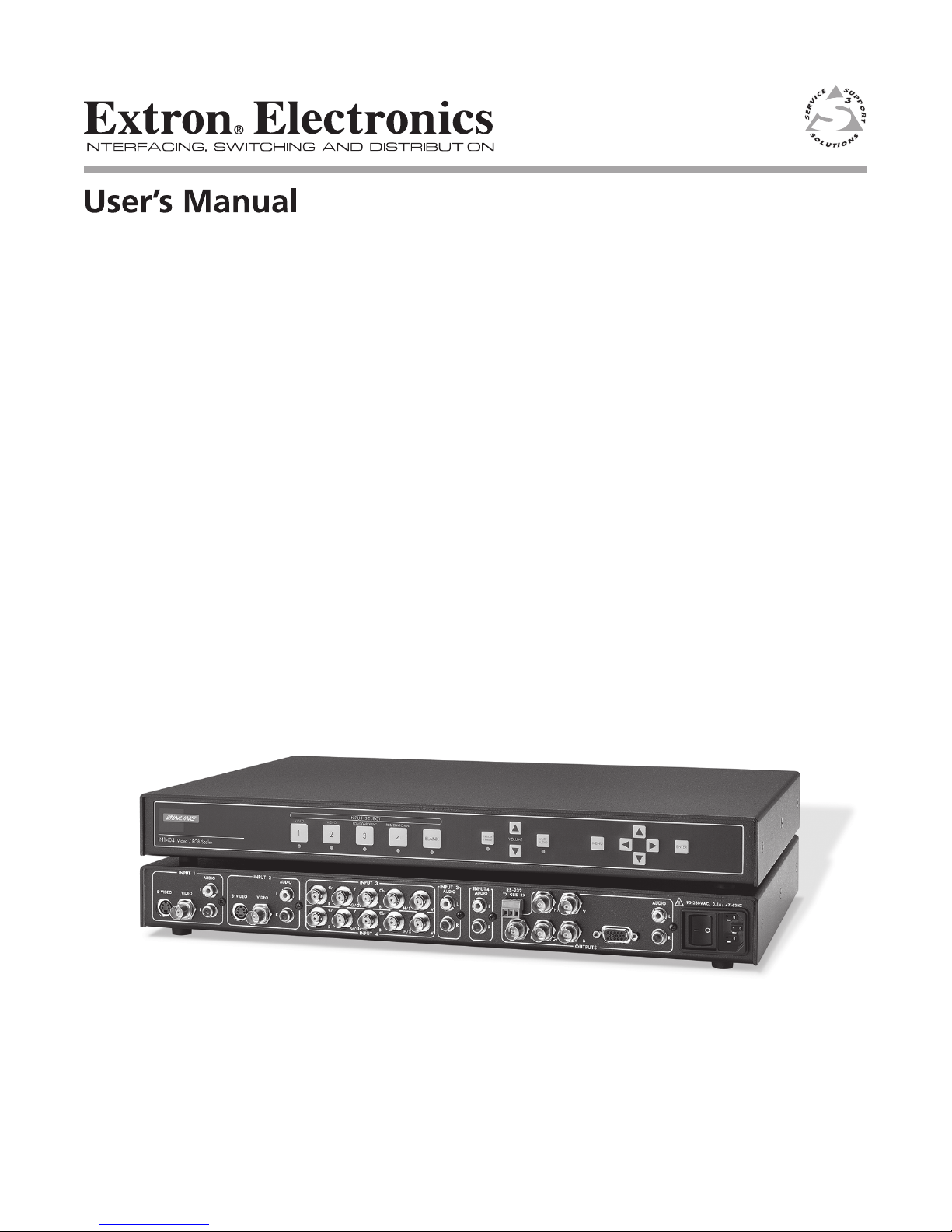
IN1404
Video Scaler
68-1078-01
Rev. A
12 04
Page 2

Precautions
Safety Instructions • English
This symbol is intended to alert the user of important operating and maintenance
(servicing) instructions in the literature provided with the equipment.
This symbol is intended to alert the user of the presence of uninsulated dangerous
voltage within the product's enclosure that may present a risk of electric shock.
Caution
Read Instructions • Read and understand all safety and operating instructions before using the
equipment.
Retain Instructions • The safety instructions should be kept for future reference.
Follow Warnings • Follow all warnings and instructions marked on the equipment or in the user
information.
Avoid Attachments • Do not use tools or attachments that are not recommended by the equipment
manufacturer because they may be hazardous.
Consignes de Sécurité • Français
Ce symbole sert à avertir l’utilisateur que la documentation fournie avec le matériel
contient des instructions importantes concernant l’exploitation et la maintenance
(réparation).
Ce symbole sert à avertir l’utilisateur de la présence dans le boîtier de l’appareil de
tensions dangereuses non isolées posant des risques d’électrocution.
Attention
Lire les instructions• Prendre connaissance de toutes les consignes de sécurité et d’exploitation avant
d’utiliser le matériel.
Conserver les instructions• Ranger les consignes de sécurité afin de pouvoir les consulter à l’avenir.
Respecter les avertissements • Observer tous les avertissements et consignes marqués sur le matériel ou
présentés dans la documentation utilisateur.
Eviter les pièces de fixation • Ne pas utiliser de pièces de fixation ni d’outils non recommandés par le
fabricant du matériel car cela risquerait de poser certains dangers.
Sicherheitsanleitungen • Deutsch
Dieses Symbol soll dem Benutzer in der im Lieferumfang enthaltenen
Dokumentation besonders wichtige Hinweise zur Bedienung und Wartung
(Instandhaltung) geben.
Dieses Symbol soll den Benutzer darauf aufmerksam machen, daß im Inneren des
Gehäuses dieses Produktes gefährliche Spannungen, die nicht isoliert sind und
die einen elektrischen Schock verursachen können, herrschen.
Achtung
Lesen der Anleitungen • Bevor Sie das Gerät zum ersten Mal verwenden, sollten Sie alle Sicherheits-und
Bedienungsanleitungen genau durchlesen und verstehen.
Aufbewahren der Anleitungen • Die Hinweise zur elektrischen Sicherheit des Produktes sollten Sie
aufbewahren, damit Sie im Bedarfsfall darauf zurückgreifen können.
Befolgen der Warnhinweise • Befolgen Sie alle Warnhinweise und Anleitungen auf dem Gerät oder in
der Benutzerdokumentation.
Keine Zusatzgeräte • Verwenden Sie keine Werkzeuge oder Zusatzgeräte, die nicht ausdrücklich vom
Hersteller empfohlen wurden, da diese eine Gefahrenquelle darstellen können.
Warning
Power sources • This equipment should be operated only from the power source indicated on the
product. This equipment is intended to be used with a main power system with a grounded
(neutral) conductor. The third (grounding) pin is a safety feature, do not attempt to bypass or
disable it.
Power disconnection • To remove power from the equipment safely, remove all power cords from
the rear of the equipment, or the desktop power module (if detachable), or from the power
source receptacle (wall plug).
Power cord protection • Power cords should be routed so that they are not likely to be stepped on or
pinched by items placed upon or against them.
Servicing • Refer all servicing to qualified service personnel. There are no user-serviceable parts
inside. To prevent the risk of shock, do not attempt to service this equipment yourself because
opening or removing covers may expose you to dangerous voltage or other hazards.
Slots and openings • If the equipment has slots or holes in the enclosure, these are provided to
prevent overheating of sensitive components inside. These openings must never be blocked by
other objects.
Lithium battery • There is a danger of explosion if battery is incorrectly replaced. Replace it only
with the same or equivalent type recommended by the manufacturer. Dispose of used batteries
according to the manufacturer's instructions.
Avertissement
Alimentations• Ne faire fonctionner ce matériel qu’avec la source d’alimentation indiquée sur
l’appareil. Ce matériel doit être utilisé avec une alimentation principale comportant un fil de
terre (neutre). Le troisième contact (de mise à la terre) constitue un dispositif de sécurité :
n’essayez pas de la contourner ni de la désactiver.
Déconnexion de l’alimentation• Pour mettre le matériel hors tension sans danger, déconnectez tous
les cordons d’alimentation de l’arrière de l’appareil ou du module d’alimentation de bureau (s’il
est amovible) ou encore de la prise secteur.
Protection du cordon d’alimentation • Acheminer les cordons d’alimentation de manière à ce que
personne ne risque de marcher dessus et à ce qu’ils ne soient pas écrasés ou pincés par des
objets.
Réparation-maintenance • Faire exécuter toutes les interventions de réparation-maintenance par un
technicien qualifié. Aucun des éléments internes ne peut être réparé par l’utilisateur. Afin
d’éviter tout danger d’électrocution, l’utilisateur ne doit pas essayer de procéder lui-même à ces
opérations car l’ouverture ou le retrait des couvercles risquent de l’exposer à de hautes tensions
et autres dangers.
Fentes et orifices • Si le boîtier de l’appareil comporte des fentes ou des orifices, ceux-ci servent à
empêcher les composants internes sensibles de surchauffer. Ces ouvertures ne doivent jamais
être bloquées par des objets.
Lithium Batterie • Il a danger d'explosion s'll y a remplacment incorrect de la batterie. Remplacer
uniquement avec une batterie du meme type ou d'un ype equivalent recommande par le
constructeur. Mettre au reut les batteries usagees conformement aux instructions du fabricant.
Vorsicht
Stromquellen • Dieses Gerät sollte nur über die auf dem Produkt angegebene Stromquelle betrieben
werden. Dieses Gerät wurde für eine Verwendung mit einer Hauptstromleitung mit einem
geerdeten (neutralen) Leiter konzipiert. Der dritte Kontakt ist für einen Erdanschluß, und stellt
eine Sicherheitsfunktion dar. Diese sollte nicht umgangen oder außer Betrieb gesetzt werden.
Stromunterbrechung • Um das Gerät auf sichere Weise vom Netz zu trennen, sollten Sie alle
Netzkabel aus der Rückseite des Gerätes, aus der externen Stomversorgung (falls dies möglich
ist) oder aus der Wandsteckdose ziehen.
Schutz des Netzkabels • Netzkabel sollten stets so verlegt werden, daß sie nicht im Weg liegen und
niemand darauf treten kann oder Objekte darauf- oder unmittelbar dagegengestellt werden
können.
Wartung • Alle Wartungsmaßnahmen sollten nur von qualifiziertem Servicepersonal durchgeführt
werden. Die internen Komponenten des Gerätes sind wartungsfrei. Zur Vermeidung eines
elektrischen Schocks versuchen Sie in keinem Fall, dieses Gerät selbst öffnen, da beim Entfernen
der Abdeckungen die Gefahr eines elektrischen Schlags und/oder andere Gefahren bestehen.
Schlitze und Öffnungen • Wenn das Gerät Schlitze oder Löcher im Gehäuse aufweist, dienen diese
zur Vermeidung einer Überhitzung der empfindlichen Teile im Inneren. Diese Öffnungen dürfen
niemals von anderen Objekten blockiert werden.
Litium-Batterie • Explosionsgefahr, falls die Batterie nicht richtig ersetzt wird. Ersetzen Sie
verbrauchte Batterien nur durch den gleichen oder einen vergleichbaren Batterietyp, der auch
vom Hersteller empfohlen wird. Entsorgen Sie verbrauchte Batterien bitte gemäß den
Herstelleranweisungen.
Instrucciones de seguridad • Español
Este símbolo se utiliza para advertir al usuario sobre instrucciones importantes de
operación y mantenimiento (o cambio de partes) que se desean destacar en el
contenido de la documentación suministrada con los equipos.
Este símbolo se utiliza para advertir al usuario sobre la presencia de elementos con
voltaje peligroso sin protección aislante, que puedan encontrarse dentro de la caja
o alojamiento del producto, y que puedan representar riesgo de electrocución.
Precaucion
Leer las instrucciones • Leer y analizar todas las instrucciones de operación y seguridad, antes de usar
el equipo.
Conservar las instrucciones • Conservar las instrucciones de seguridad para futura consulta.
Obedecer las advertencias • Todas las advertencias e instrucciones marcadas en el equipo o en la
documentación del usuario, deben ser obedecidas.
Evitar el uso de accesorios • No usar herramientas o accesorios que no sean especificamente
recomendados por el fabricante, ya que podrian implicar riesgos.
Advertencia
Alimentación eléctrica • Este equipo debe conectarse únicamente a la fuente/tipo de alimentación
eléctrica indicada en el mismo. La alimentación eléctrica de este equipo debe provenir de un
sistema de distribución general con conductor neutro a tierra. La tercera pata (puesta a tierra) es
una medida de seguridad, no puentearia ni eliminaria.
Desconexión de alimentación eléctrica • Para desconectar con seguridad la acometida de
alimentación eléctrica al equipo, desenchufar todos los cables de alimentación en el panel trasero
del equipo, o desenchufar el módulo de alimentación (si fuera independiente), o desenchufar el
cable del receptáculo de la pared.
Protección del cables de alimentación • Los cables de alimentación eléctrica se deben instalar en
lugares donde no sean pisados ni apretados por objetos que se puedan apoyar sobre ellos.
Reparaciones/mantenimiento • Solicitar siempre los servicios técnicos de personal calificado. En el
interior no hay partes a las que el usuario deba acceder. Para evitar riesgo de electrocución, no
intentar personalmente la reparación/mantenimiento de este equipo, ya que al abrir o extraer las
tapas puede quedar expuesto a voltajes peligrosos u otros riesgos.
Ranuras y aberturas • Si el equipo posee ranuras o orificios en su caja/alojamiento, es para evitar el
sobrecalientamiento de componentes internos sensibles. Estas aberturas nunca se deben obstruir
con otros objetos.
Batería de litio • Existe riesgo de explosión si esta batería se coloca en la posición incorrecta. Cambiar
esta batería únicamente con el mismo tipo (o su equivalente) recomendado por el fabricante.
Desachar las baterías usadas siguiendo las instrucciones del fabricante.
Page 3

Table of Contents
Product Overview............................................................................................................ 2
Description...................................................................................................................... 2
Features........................................................................................................................... 2
Compatibility..................................................................................................................... 3
Input................................................................................................................................ 3
Output............................................................................................................................. 4
Installation.......................................................................................................................... 4
IN1404 application diagram .......................................................................................... 6
IN1404 rear panel connectors........................................................................................ 6
Operation............................................................................................................................. 8
Front panel controls ....................................................................................................... 8
IN1404 on-screen display menu system ........................................................................ 9
On-screen menu ........................................................................................................... 10
Menu Commands........................................................................................................... 10
Video menu .................................................................................................................. 10
Audio menu.................................................................................................................. 12
Input menu ................................................................................................................... 13
Output menu ................................................................................................................ 17
Advanced menu ........................................................................................................... 18
Choosing the Optimal Resolution and Refresh Rate................................... 19
CRT displays: Selecting the golden resolution .......................................................... 19
CRT displays: Selecting the optimal refresh rate....................................................... 20
Fixed pixel displays: Selecting the optimal resolution and refresh rate.................. 20
Advanced Operation .................................................................................................... 22
Pass-through RGB video............................................................................................... 22
Output RGB connectors ............................................................................................... 22
Output modes............................................................................................................... 22
Default power-up buttons........................................................................................... 23
Output positioning ...................................................................................................... 23
Advanced Input Settings ........................................................................................... 23
Adjustment advanced input settings.......................................................................... 25
Input blanking adjustment.......................................................................................... 25
Active area adjustment ................................................................................................ 26
Total pixels adjustment................................................................................................ 28
Remote Operation......................................................................................................... 29
RS-232 Control .............................................................................................................. 29
IN1404 serial commands .............................................................................................. 30
Troubleshooting............................................................................................................. 34
Specifications
.................................................................................................................. 39
Part Numbers .................................................................................................................. 40
Cables .................................................................................................................................. 41
Page 4

Product Overview
Description
The IN1404 is a full-featured video and RGB scaler that combines digital video decoding, advanced
video scaling and a 4-input A/V switcher into a single product. The IN1404 uses sophisticated digital
video decoding and scaling technology to convert a composite video, S-video, interlaced or
progressive component video signal and RGB signals (at various scan rates and resolutions) to
standard VGA and HDTV resolutions and refresh rates.
Features
Superb Video Scaling Technology — Employing sophisticated video de-interlacing, scaling and
filtering techniques, the IN1404 offers an output signal with outstanding image detail and enhanced
brightness that is entirely free of visible scan lines. The scaler automatically senses the origin of the
video source material and selects the optimum motion compensation formula to eliminate unwanted
artifacts in the output image. The IN1404 employs high bandwidth digital signal processing, high
speed digital to analog conversion, and sophisticated filtering and sharpness circuitry to maintain and
enhance image detail, even at the highest output resolutions.
Advanced Quad Standard Video Decoding — A high quality video decoder in the IN1404 provides
accurate video decoding of composite video and S-video signals in the NTSC, PAL, SECAM and NTSC
4.43 video standards. The video decoder employs an advanced 3-line adaptive comb filter for
composite video signals and greatly reduces cross-color interference and hanging dots, while
maintaining maximum image bandwidth and detail.
Advanced RGB Scaling — The IN1404 also provides superb upscaling and refresh rate changing for
640 x 480, 800 x 600 and 1024 x 768 resolution RGB video signals, making it an excellent companion for
LCD and DLP display devices that have marginal, on-board video scaling capability. The unit can
accept standard and non-standard RGBHV, RGBS and RGsB signals at horizontal scan rates from
15 KHz - 60 KHz and scale them up to the desired resolution and refresh rate.
Selectable Output Resolution — The IN1404 offers a wide range of output resolutions to match the
optimum or native resolution of virtually any display device. The IN1404 provides a progressive scan
output signal at standard resolutions and refresh rates, ensuring optimal compatibility and
exceptional image quality with a wide range of CRT, LCD, DMD, ILA, D-ILA, and plasma display
devices.
Selectable Refresh Rate — The IN1404 output vertical refresh rate is adjustable from 60 Hz to 120 Hz.
By converting PAL (50 Hz) and NTSC (60 Hz) input signals to higher, more ergonomic refresh rates,
the scaler makes it possible to display a remarkably solid, flicker-free image when using CRT monitors
and projectors. The chart on page 22 indicates the available output resolutions and refresh rates.
4-input Video / Audio Switcher — The IN1404 provides multiple inputs and flexible switching
capability to accommodate a variety of applications. Inputs 1 and 2 can each accept a composite video
or S-video signal. Inputs 3 and 4 accept composite video, S-video, component video, progressive
component video, RGB, RGBS, or RGBHV signals. Inputs 3 and 4 can also be set for passive mode in
which they provide no decoding, scaling or refresh rate changing. Stereo audio-follow-video
switching is provided for all four inputs.
Digital Freeze Frame — Provides a high quality still image for applications that require close
examination of a specific video frame. Freeze frame operates for video signals and RGB signals that
are being routed through the RGB scaling circuitry. Freeze is not available when the input is
configured for RGB passive.
Video Blank button — Located adjacent to the Input Select buttons, the BLANK button allows the
video image to be suppressed. When blank is engaged, the output signals go to black; but the sync
signals continue, ensuring that the data display device retains sync lock. When the BLANK button is
pressed a second time, the previously selected input is once again displayed. The blank feature can
also be engaged or disengaged using an RS-232 serial command. Video blanking is not available when
the input is configured for RGB passive.
2
IN1404 User’s Manual
Page 5

On-screen Menus — Provide easy control of video adjustments, including hue, color, contrast,
brightness, gamma, sharpness, image size, image position and edge blanking. Individual image
settings can be optimized and stored for each input. Each time an input is selected, all image settings
stored for that input are automatically recalled. The on-screen menus also make it easy to verify and
adjust advanced settings such as output signal resolution/refresh rate/sync format, RS-232 control
options and reset to factory default. System Info is a handy menu option that uses the on-screen
display to show comprehensive information about the input and output signals and scaler settings.
Image Size, Position and Edge Blanking Controls — Individual horizontal and vertical image
adjustments make it easy to precisely fit the active video image to the display area and provide for
multiple aspect ratios. The digital Freeze Frame feature can be activated using a front panel button or
via RS-232 serial commands.
Comprehensive Input Adjustment Controls — Include signal format, aspect ratio and horizontal
tracking. Once adjustments are made to optimize input signals, these settings are stored and
automatically recalled when the same input source is selected again.
Advanced Input Adjustment Controls — Provided to optimize the unit when it is used with
proprietary and non-standard input signals. These input signal adjustments include: Total Pixels,
Active Pixels, Active Lines, horizontal and vertical blanking, Phase and Scan Type. Once adjustments
are made to optimize non-standard input signals, these settings are stored and automatically recalled
when the same input signal is encountered again.
Blue Screen Feature — Provides a full screen blue image for setup and testing purposes. The blue
screen output signal (activated via the on-screen menu) is always available, even when the input
signal is missing or the input settings are incorrectly adjusted. Blue screen acts as a test signal and is
ideal for setting up the output resolution, refresh rate and position settings, and to verify connection to
the output display device.
128 User Memories — The IN1404 includes 128 user memories that store all video, audio and input
parameters. User memories allow the unit to be optimized for a large number of sources and gives the
capability to recall those settings quickly. The user memories make it easy to expand the number of
inputs by using a switcher or matrix switcher before the IN1404.
RS-232 Serial Control — Provided for all scaler functions, including input selections, image
adjustments and output settings. The IN1404’s comprehensive RS-232 control capacity facilitates
complete system integration and effortless control when combined with a third party control system.
Data Display Friendly Output — The IN1404 provides a progressive scan RGBHV output at standard
VGA resolutions and refresh rates, ensuring optimal compatibility with a wide range of CRT, LCD,
DMD, ILA, D-ILA, and plasma display devices.
Dual Outputs — The IN1404 features a 5-BNC output and a 15-Pin HD (VGA) output. Since both are
active simultaneously, the IN1404 can directly drive two separate display devices.
Rack Mountable — The IN1404 can be mounted in a 1U rack space using the provided mounting
brackets (Extron part # 70-391-01).
Compatibility
Input
The IN1404 Video Scaler accepts composite and S-video signals in the NTSC, PAL, SECAM and
NTSC 4.43 video standards on all four inputs. Inputs 3 and 4 also accept interlaced and progressive
scan component video, interlaced and progressive scan RGBHV, RGBS or RGsB analog video signals
at horizontal scan rates from 15 kHz to 60 kHz. When inputs 3 and 4 are set for passive mode, they are
compatible with virtually any signal format at any resolution and refresh rate within the range of
15-60 kHz.
The IN1404 has stereo audio-follow-video capability. All four stereo audio inputs are compatible with
unbalanced line level signals from a VCR, DVD player, computer audio card, or any other audio
device that delivers a stereo line level signal.
IN1404 User’s Manual
3
Page 6

Output
The IN1404 features selectable output resolutions from 640 x 480 up to 1365 x 1024 to match the
optimum or native resolution of virtually any display device. The unit provides a progressive scan
output signal at standard resolutions and refresh rates, ensuring optimal compatibility and
exceptional image quality with a wide range of CRT, LCD, DMD, ILA, D-ILA, and plasma display
devices.
The output refresh rate is also selectable as desired. When the IN1404 is used with LCD or DMD
displays, the 60 Hz output setting is recommended. Higher output refresh rates may be selected for
use on CRT type displays in order to reduce flicker and provide enhanced ergonomics. The chart on
page 22 indicates the available output resolutions and refresh rates.
The IN1404 provides dual outputs to 5 BNC connectors and a 15-Pin HD (VGA) connector. Since both
are active simultaneously, the IN1404 can directly drive two separate display devices. The output
signal format can be set to RGBHV, RGBS or RGsB as required (see page 18).
The stereo audio output provides an unbalanced line level signal (identical to the input signal). This
output can drive any line level compatible audio unit, or a local device such as powered speakers.
Installation
This section offers step-by-step instructions for installing the IN1404 Video Scaler. An application
diagram is provided on page 6.
CAUTION
1. Place/install the IN1404 at the desired location. Make sure that the unit is seated on a flat surface
or is securely installed in a standard 19” equipment rack using the mounting brackets provided
(70-391-01). The IN1404 is exactly 1U high without the feet. If other equipment will be located in
the space directly below the scaler, the rubber feet on the bottom of the unit must be removed
before mounting it in the equipment rack.
2. Connect the video and computer video sources to the appropriate IN1404 input(s). Any of the
four inputs can accept either a composite video signal or an S-video signal. Inputs 3 and 4 can
also accept component video, progressive component video, RGBHV, RGBS or RGsB signals. See
IN1404 rear panel connectors on page 6 for more details.
• Composite video sources with BNC output connectors can connected using an 26-383
• S-video sources may be connected via a 26-316 series S-video cable.
CAUTION
• Component video sources and progressive component video sources may be connected
• RGsB / RGBS / RGBHV video signals from video and computer video sources can be
Read the instructions carefully before initiating the installation procedure. Make sure that
there is no power connected to the IN1404, and that the power button is off.
series single coax cable (available in lengths from 3’ to 300’). Devices with an RCA
output connector can be connected using a BNC to RCA adapter cable.
On Inputs 1 and 2, Video input signals must only be connected to either the composite video
or the S-video connector on any one input. DO NOT connect composite video and S-video
signals simultaneously on the same input!
to input 3 or input 4 using a BNCM-RCAF RCA to BNC adapter or a 26-210 series
4-BNC cable. Take care that the component video signals are connected to the correct
connectors. For more information on component/progressive component video
connections, see the chart on page 7.
connected to input 3 or input 4 by using four or five BNC cables or a multi-conductor
RGBHV, RGBS or RGB "snake". The 26-210/26-260 series cables are well suited for this
purpose (see Cables on page 41). While making connections, take care to insure that the
red output is connected to the red input, green output to the green input, etc.
4
IN1404 User’s Manual
Page 7

3. Connect the audio signals to the appropriate IN1404 stereo audio inputs. Computer sound cards
and other devices with a 3.5 mm mini output connector can be connected using an optional
IN9107 3.5 mm stereo mini male to (2) RCA male cable.
4. The IN1404 features a 5-BNC output and a 15-Pin HD output for easy connections to a variety of
scan rate compatible displays:
• Display devices with a 15-pin HD input can be connected directly to the IN1404 15-pin
HD output port using a standard VGA cable. The 26-112 series flexible VGA cables offer
exceptional performance and are available in a variety of lengths.
• Display devices that feature a BNC input connectors can be connected directly to the
IN1404 BNC output using four or five BNC cables (for RGsB, RGBS or RGBHV,
respectively) or a multi-conductor RGBHV, RGBS or RGB cable. The 26-210/26-260
series cables are well suited for this purpose (see Cables on page 41). While making
connections, take care to insure that the red output is connected to the red input, green
output is connected to the green input, etc.
Since both outputs are active simultaneously, the IN1404 can directly drive two separate
display devices.
5. Connect the IN1404 stereo audio output to the audio system’s input (mixer, amplifier, powered
speakers, etc.).
6. If desired, connect a control system, computer or other serial command source to the RS-232
remote connector. For more information about remote control of the IN1404, see the Remote
Operation on page 29.
7. Connect power to the IN1404 using the IEC power cable (included).
8. Turn on the video sources, the IN1404, the data display device(s) and the audio output equipment
(if applicable).
9. Using the front panel controls or RS-232 commands, adjust and store the parameters for each
input source.
CAUTION
It is very important that you set each input for composite video, S-video, component video,
progressive component video or RGB operation as appropriate to match the format of the
input signal (see input menu on page 13 for more details).
10. Set the output resolution and refresh rate to match your display device/installation requirement.
Refer to Output menu on page 17.
IN1404 User’s Manual
5
Page 8

IN1404 application diagram
Figure 1. — IN1404 application diagram
IN1404 rear panel connectors
Inputs 1-2 Inputs 3-4 Output Other
S-VIDEO:
(1) 4-Pin mini DIN
connector
COMPOSITE VIDEO:
(1) BNC connector
STEREO AUDIO:
(2) RCA female for Left
and Right Audio
RGBHV / CrYCb:
5 BNC connectors for
universal inputs:
composite, S-video,
component, progressive
component, RGBHV,
RGBS, RGsB and RGB
passive.
STEREO AUDIO:
(2) RCA female for left
and right audio
VGA:
15-Pin HD female
connector with standard
VGA pin-outs
RGBHV:
(5) BNC Connectors—
output format selectable:
RGBHV / RGBS / RGsB
STEREO AUDIO:
(2) RCA female for left
and right audio
RS-232:
Phoenix connector—
Pin 1: TX, Pin 2: Ground,
Pin 3: RX
POWER:
Universal Power—
90 - 260 VAC, 47 - 63 Hz
6
IN1404 User’s Manual
Page 9
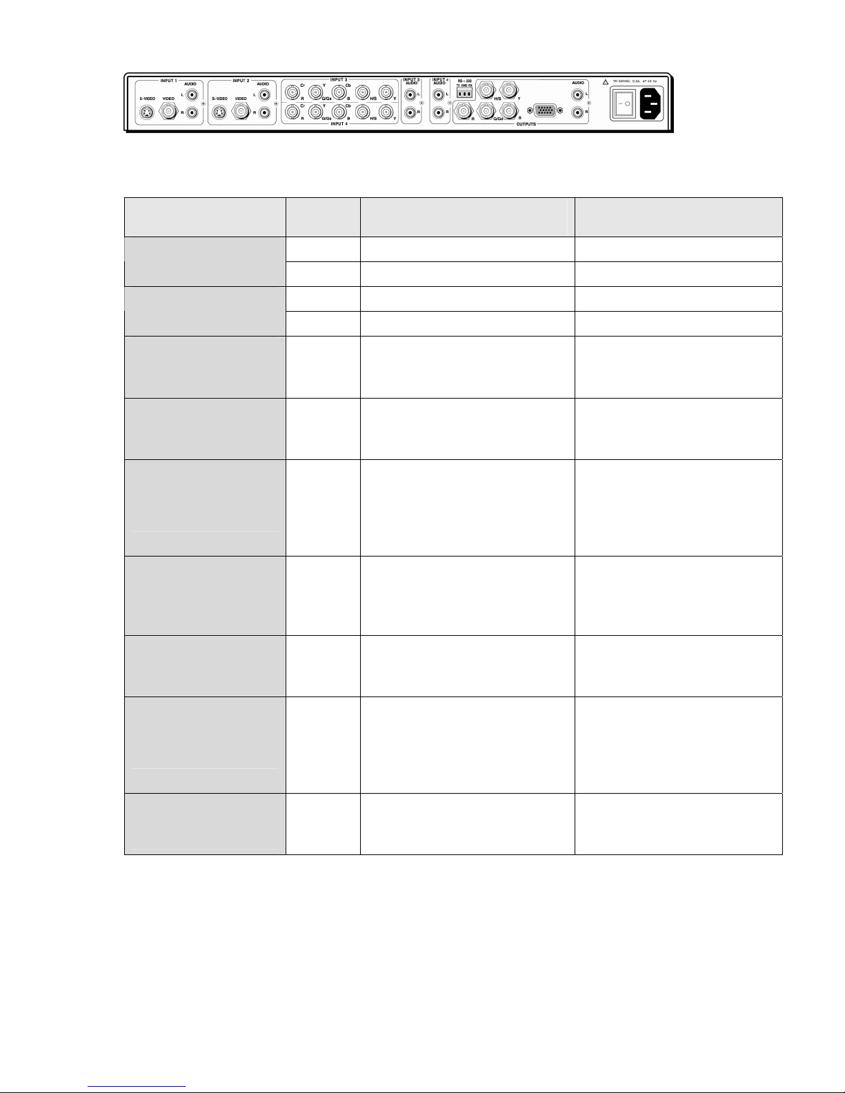
Figure 2. — Rear panel of the IN1404 scaler
Connect the video signals to the rear of the IN1404 as shown in the table below:
Signal format Inputs Signal Connection
1, 2 Composite Video BNC Composite
3, 4 Composite Y BNC
1, 2 S-video S-video (Mini DIN) S-video
3, 4 Chroma / CY Cr BNC, Y BNC
Component interlaced 3, 4
Component progressive 3, 4
RGBHV
(RGB with separate
horizontal and vertical
sync)
RGBS
(RGB with Composite
sync)
RGsB
(RGB with sync on
green)
RGBHVS passive
(RGB passive with either
horizontal and vertical
sync or Composite sync)
3, 4
3, 4
3, 4
3, 4
R - Y / Cr / Pr
Y
B - Y / Cb / Pb
R - Y / Cr / Pr
Luma / Y
B - Y / Cb / Pb
Red
Green
Blue
horizontal sync
vertical sync
Red
Green
Blue
Composite sync
Red
Green/sync
Blue
Red
Green
Blue
Horiz/Comp sync
vertical sync
Cr BNC
Y BNC
Cb BNC
Cr BNC
Y BNC
Cb BNC
R BNC
G BNC
B BNC
H BNC
V BNC
R BNC
G BNC
B BNC
S BNC
R BNC
Gs BNC
B BNC
R BNC
G BNC
B BNC
H/S BNC
V BNC
RGsB passive
(RGB passive with sync
on green)
IN1404 User’s Manual
3, 4
Red
Green/sync
Blue
R BNC
Gs BNC
B BNC
7
Page 10
Operation
This section focuses on operating the IN1404 using the front panel controls and commands. All video
and audio adjustments, setup functions and switching operations can be performed through the front
panel or via RS-232 serial controls. Remote operation information can be found on page 29.
Front panel controls
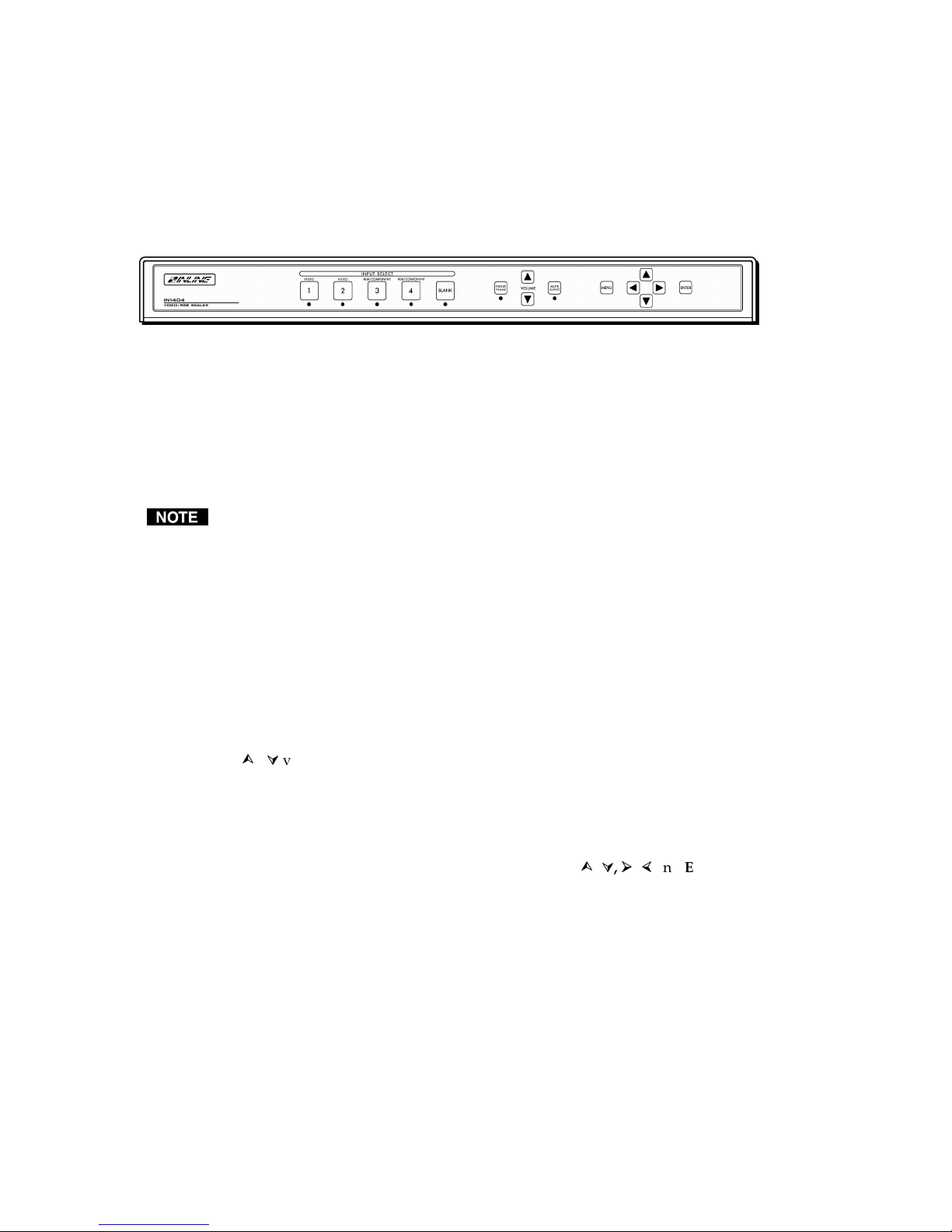
Figure 3. — Front panel of the IN1404 scaler
Input Select: The large buttons labeled INPUT 1, INPUT 2, INPUT 3 and INPUT 4 in the Input
Select section are used to select the desired input. After turning on the IN1404, press and release the
desired Input Select button. A green LED will light underneath the button to indicate the selected
input. The stereo audio signal associated with the input will automatically be selected at the same
time. All audio, video, and input settings for each input are stored internally (in memory) so the
adjustment(s) will not have to be repeated after they are optimized. To switch to another input,
simply press and release another numbered Input Select button.
When powered up, the scaler automatically returns to the last configuration, including the last
input selected.
Blank: The BLANK button can be used at any time to show a blank screen on the display device.
When blank is engaged, the output setting goes to black but the sync signals continue, ensuring that
the data display device retains sync lock. Simply press and release the button to engage blanking (the
green LED underneath the button will illuminate), and press and release it to disengage. The BLANK
button has no effect on input 3 or input 4, which are configured as passive inputs.
Freeze Frame: Allows users to freeze the video signal and display a still image. Simply press and
release the button to engage the function (the green LED below the button will illuminate), then press
and release again to disengage. The freeze frame button has no effect on input 3 or input 4, which are
configured as passive inputs.
Volume: The volume buttons are used to regulate the level of the audio signals routed through the
scaler. Use the
Press and release a button to raise or lower the volume level by one step, or press and hold a button to
change the level continuously. The IN1404 saves the volume levels for each input.
Mute Audio: Mutes the audio for the selected input. Press the button to engage (the green LED
below the button will illuminate), and press it again to disengage.
Menu Buttons: The remaining buttons on the front panel (MENU,
to access and adjust the on-screen menu displays.
system is provided on the next page.
/ volume buttons to increase or decrease the audio level for the current input.
, , ,
and ENTER) are used
An illustration of the on-screen display menu
8
IN1404 User’s Manual
Page 11
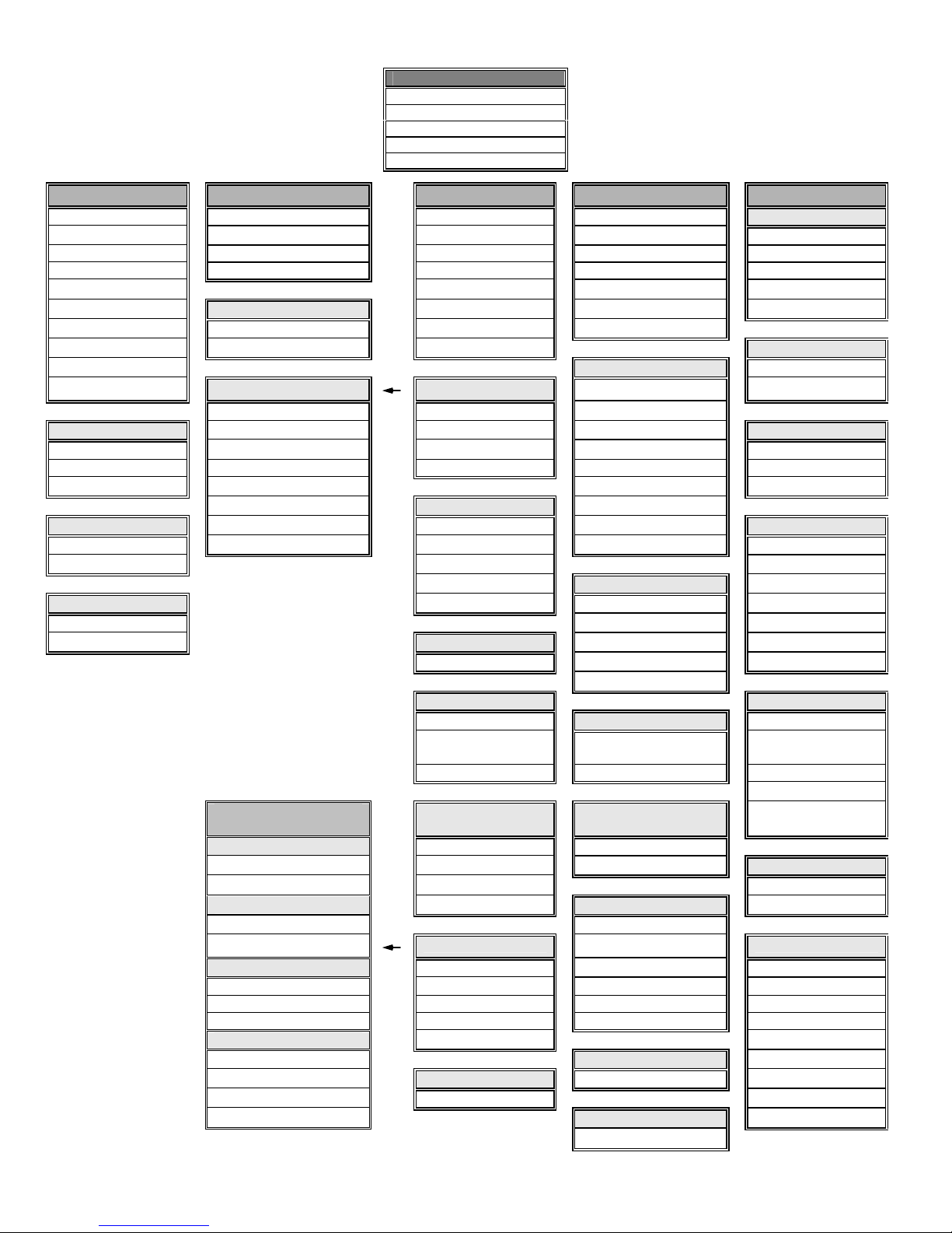
IN1404 on-screen display
menu system
Video Audio
Brightness Bass Signal Format Resolution Factory Reset
Contrast Treble Aspect Ratio Refresh Rate User Memory
RGB Gain3 Balance Auto Switching Size Baud Rate
Color Saturation2 Reset Audio Input Labels Position Delimiters
Hue2 Horiz. Tracking Sync Format Reset RS-232
Sharpness2 Reset Audio Phase Blue Screen System Info
Gamma2 Yes Advanced Reset Output
Noise Filter2 No Reset Input Factory Reset
Comp/Trap2 Resolution Yes
Reset Video Input #
Composite Input 1 800 x 600
RGB Gain3 S-video Input 2 852 x 480 User Memory
Red Component Interlaced4 Input 3 1024 x 768 Save
Green Component Input 4 1152 x 864 Recall
Blue RGBS4 1280 x 720 Reset
RGsB4 Aspect Ratio 1280 x 1024
Comb/Trap2 RGBHVS Passive4 Standard 1365 x 768 Baud Rate
Comb Filter On RGsB Passive4 Anamorphic 1365 x 1024 1200
Trap Filter On Wide Screen 2400
Wider Screen Refresh Rate5 4800
Reset Video Tomarama 56 / 60 / 65 Hz 9600
Yes 72 / 75 Hz 19200
No Auto Switching 85 / 96 Hz 38400
On / Off 100 Hz 57600
120 Hz
Input Labels Delimiters
On / Off Size Parenthesis
Momentary H-Size Brackets
Main Menu
Video
Audio
Input
Output
Advanced
Input Output Advanced
Signal Format 640 x 480 No
Reset label V-Size Slashes
Less & Greater
Advanced Features
(under Input menu)
Active Area Very Fast H-Position
Active Pixels Fast V-Position Reset RS-232
Active Lines Normal Yes
Blanking Slow Sync Format No
H-Blanking RGBHV--
V-Blanking
Scan Type3 Active Area RGBS A Input #
Interlaced Blanking RGBS B Signal Format
Swap Fields Total Pixels3 RGsB A Input Horiz.
Invert Sync Scan Type RGsB B Input Vert.
Input Mode Input Mode Output Size
Auto Detect Blue Screen Output Horiz.
Lockout Changes Reset Input On/Off Output Vert.
User Defined Yes / No Sync Format
Redetect Now
IN1404 User’s Manual
Horizontal
Tracking3
Advanced RGBHV++ System Info
Position Signs !#
Reset Output
Yes/No
Version
9
Page 12

On-screen menu
To access the main menu, press the MENU or ENTER button. Use the arrow buttons to maneuver
around within the menu display. Press ENTER to select and save a command, or press MENU to
escape to the previous menu or to clear the menu display. All audio, video, input, and output settings
for each input and each output mode are stored internally (in memory) so the adjustments will not
have to be repeated after they are optimized.
The Main Menu commands and their functions are:
Video: Changes input signal video parameters.
Audio: Changes input signal audio parameters.
Input: Changes input signal timing format parameters.
Output: Changes output signal resolution and format parameters.
Advanced: Displays advanced options.
Menu Commands
Video menu
The IN1404 allows you to manually adjust the brightness, contrast, color, hue, sharpness, gamma,
noise filter, and comb/trap filter settings.
To access the video adjustment menu via the front panel control buttons
1. Press the desired Input Select button.
2. Press MENU.
3. Press the
4. Press ENTER.
5. Use the
6. After selecting a setting, use the
7. Press and release a button to move one step in either direction.
8. Press and hold a button to move continuously through the adjustment range.
9. Press ENTER to save when the input is optimized.
CAUTION
The following video adjustment parameters can be controlled via the on-screen menu system (front
panel buttons). Remote operation instructions can be found on page 29.
Brightness setting adjusts the input signal brightness.
Range: 0 to 255
Factory default setting: 128
Operation:
Press
or button (if necessary) to reach the video menu.
and buttons and the ENTER key to select the setting you wish to adjust.
and buttons to make the adjustments.
It is critical that you save the setting before proceeding to another input or another menu
function; otherwise, your new adjustment will be lost.
button to increase the brightness.
Press
button to decrease the brightness.
10
IN1404 User’s Manual
Page 13

Contrast adjusts the difference between the input signal’s brightest and darkest settings. The
minimum setting displays at about the same brightness (very grayish). The maximum setting displays
a noticeable difference between the darkest and lightest parts of the screen.
Range: 0 to 255
Factory default setting: 128
Operation:
Press
button to increase the contrast.
Press
button to decrease the contrast.
RGB Gain changes the input signal gain (contrast) for each individual color (applies to component B,
RGBHV, RGBS and RGsB signal format only). Red, green and blue are available.
Range: 0 to 255
Factory default setting: 128
Operation:
Press
Press
Color Saturation adjusts the color saturation of the picture over a wide range. Setting this control to 0
removes most of the color. This applies to composite, S-video and component A signal formats only.
button to increase the RGB Gain.
button to decrease the RGB Gain.
Range: 0 to 255
Factory default setting: 128
Operation:
Press
Press
Hue (NTSC signals only) adjusts the picture’s color towards red or green. This applies to composite,
S-video and component A signal formats only.
Range: 0 to 255
Factory default setting: 128
Operation:
Press
Press
Sharpness uses variable filtering to affect input picture detail and definition. This applies to
composite, S-video and component A signal formats only.
button to increase the color.
button to decrease the color.
button to increase the green.
button to increase the red.
Increasing the sharpness setting produces the visual effect that the noise filter setting is decreasing.
Although the sharpness and noise filter settings seem to offset each other, they are actually two
different adjustments that affect two different sets of circuitry. Operators should adjust both
settings until optimal picture quality is achieved.
Range: 0 to 8
Factory default setting: 3
Operation:
Press
button to increase the sharpness.
Press
button to decrease the sharpness.
IN1404 User’s Manual
11
Page 14
If the following settings seem confusing, we recommend that you experiment with the MENU,
, , ,
control operations. It’s a good idea to get comfortable using these buttons to navigate through the
on-screen menu system before moving on to other sections of this manual. If you get lost, enter
unfamiliar territory or are afraid of making an improper selection, pressing the MENU button
allows you to leave the menu system safely without making any changes. We also recommend,
unless you’re a qualified audiovisual technician, avoiding the Advanced menu.
Gamma: The 30 active gamma correction curves programmed into the IN1404 are used to compensate
for the non-linear response of many display devices. Before you adjust Gamma, the brightness and
contrast controls should be set at factory default positions. Once the proper gamma setting has been
achieved, the brightness and contrast settings should then be optimized to fine tune the image.
Range: 1 to 30
Factory default setting: 10*
Operation:
Press
button to step to higher numbered gamma curves.
Press
button to step to lower numbered gamma curves.
* The factory default setting of 10 refers to a gamma correction curve of 1.0.
Noise Filter changes the input signal noise filter. This applies to composite, S-video and component A
signal formats only.
and ENTER buttons until you familiarize yourself with the IN1402 front panel
Range: 0 to 47
Factory default setting: 9
Operation:
Press
button to increase noise filter.
Press
button to decrease noise filter.
Increasing the noise filter setting produces the effect that the picture sharpness setting is
decreasing. See the Sharpness section on the previous page.
Comb/Trap Filter selects either the comb or trap filter (only available with composite video). The
comb filter electronically provides excellent Luma/Chroma separation (separates the color from the
picture signal). This greatly reduces cross-color interference and hanging dots while maintaining
image bandwidth and detail. This applies to composite, S-video and component A signal formats
only.
The trap filter extracts luminance from the picture. Generally speaking, the trap filter is usually the
preferred setting when running signals from a VCR (as composite video). You may wish to compare
both settings to determine which is best for your application.
Reset Video resets all video settings to factory default (for current input only).
Audio menu
The IN1404 allows you to manually adjust the bass, treble, and balance settings. To access the audio
adjustment menu via the front panel control buttons, do the following:
1. Press the desired Input Select button.
2. Press MENU.
3. Press the
4. Press ENTER.
5. Use the
12
IN1404 User’s Manual
or button (if necessary) to reach the input menu.
and buttons and the ENTER key to select the setting you wish to adjust.
Page 15

6. Press ENTER to save once you’ve optimized the setting for the current input.
The following audio adjustment parameters can be controlled via the on-screen menu system (front
panel buttons). RS-232 serial control instructions can be found on page 29.
While on-screen menus are not displayed for inputs 3 and 4 when set for RGB passive mode, all
audio functions are still available for these inputs.
Bass increases/decreases the lower frequencies of the audio signal.
Range: 6 to 27
Factory Default Setting: 16 (0.0dB)
Operation:
Press
button to increase the bass frequencies.
Press
button to decrease the bass frequencies.
Treble increases/decreases the higher frequencies of the audio signal.
Range: 8 to 25
Factory Default Setting: 16 (0.0dB)
Operation:
Press
button to increase the treble frequencies.
Press
button to decrease the treble frequencies.
Balance shifts the audio balance toward the right or left audio channels.
Range: 0 to 31
Factory Default Setting: 16
Operation:
Press
Press
Reset Audio Settings resets all audio settings to factory default (for current input only).
button to move the balance toward the right channel.
button to move the balance toward the left channel.
Input menu
We recommend that you adjust the IN1404 output settings first. Adjust the resolution, refresh rate,
size, position and sync format, along with the display device settings, to fit the video image on the
screen (use the blue screen if necessary). Once the IN1404 output settings and the display device
settings have been properly adjusted, the IN404 input settings and video adjustments may be
configured for each input signal.
To access the input menu via the front panel control buttons, do the following:
1. Press the desired Input Select button.
2. Press MENU, press the
or button (if necessary) to reach the input menu.
3. Press ENTER.
4. Select the setting you wish to adjust by using the
5. Press ENTER to save once you’ve optimized the setting for the current input.
IN1404 User’s Manual
and buttons pressing ENTER.
13
Page 16

Signal format: Selects the signal format for each input. Inputs 1 and 2 can accept either composite or
S-video signals. Inputs 3 and 4 can also accept component, RGBHV, RGBS, RGsB or RGB passive. On
inputs 1 and 2, the composite and S-video connections are internally wired together; therefore, either
composite or S-video can be connected to each input, but not both at the same time. Refer to
Installation on page 4 for the specific connections for each signal format.
The available signal formats are:
• Composite
• S-video
• Component interlaced
• Component progressive
• RGBHV (RGB with separate horizontal and vertical sync)
• RGBS (RGB with composite sync)
• RGsB (RGB with sync on green)
• RGBHVS Passive (RGB passive with either horizontal and vertical sync or composite
sync)
• RGsB passive (RGB passive with sync on green)
To configure the inputs for a specific signal format, do the following:
1. Press the ENTER or MENU button to access the main menu.
2. Highlight input and press ENTER to access the input menu (use the
the appropriate menu command).
3. Highlight signal format and press ENTER to access the input selection menu.
4. Highlight the input you want to configure and press ENTER to access the signal format menu.
5. Select the signal format for each individual input (use the
signal format).
6. Press ENTER to save the signal format into memory.
CAUTION
Aspect Ratio: The aspect ratio controls can be used to vary the relative image width and height. They
can be used to accommodate various input signal aspect ratios as well as output device aspect ratios.
The output aspect ratio is selected by choosing the appropriate resolution in the output menu (see
Output modes description on page 22).
It is critical that the signal format be selected properly for each input. If the input is not
properly configured to match the input signal, the scaler will not function properly and will either
display a distorted image or no image at all. Using the on-screen menu, operators can set / change
the input signal format at any time, even when another input is active. For example, an operator
can configure the signal format for input 1 while the display device is presenting a signal that is
passing through input 3. This method is required to deselect the RGB passive signal format, since
the on-screen menu cannot be seen while in this mode. These details are discussed in
Pass-through RGB video on page 22.
Standard: For Standard 1.33 input signals (sometimes referred to as full screen)
and buttons to select the desired
and buttons to highlight
Anamorphic: This setting provides vertical image squeezing to accommodate
anamorphically enhanced DVDs.
Wide Screen: For wide screen 1.78 input signals (letterbox)
Wider Screen: For wider screen 2.35 input signals (narrow letterbox)
14
IN1404 User’s Manual
Page 17

Expand: Designed for wide screen (letterbox) signals viewed on 4:3 aspect ratio
displays. Expand mode zooms in on the center of the image and crops the
image vertically and horizontally so that the black bars above and below the
image are removed. In this mode, some image is also lost on the right and
left
hand edges.
Most DVDs and VCRs and other video source output a signal with an aspect ratio of 4:3. How this
signal is filled with active video information determines its aspect ratio. In the following four
examples, four different input aspect ratios are shown on the left as they would be displayed in their
native 4:3 format. The same signals are shown on the right as they would appear on 4:3 and 16:9
display devices with the scaler set to various aspect ratio settings.
Example 1:
Example 2
IN1404 User’s Manual
15
Page 18

Example 3
Example 4
16
IN1404 User’s Manual
Page 19

Auto Switching: The IN1404 includes an Auto Switching feature. When Auto Switching is engaged,
the IN1404 will automatically select the highest numbered input with an active video signal (e.g., if
inputs 2 and 3 are active, input 3 will be selected). If all inputs are active, input 4 will be selected, and
if no inputs are active, input 1 will be selected. Manual selection of the input is not available (from
either the front panel or the RS-232 controller) while Auto Switching is on. Auto switching works with
all signal formats, including RGB passive. To deselect Auto Switching while using RGB passive
modes, use the default power-up buttons (see page 23).
Input Labels: Each input can display a label on the screen to indicate the name of the input
selected. Select from the following label options:
On: The labels remain on-screen and change each time a new input is selected.
Off: The labels remain off and are not displayed.
Momentary: The label is displayed for 3 seconds anytime a new input is selected.
Reset: This resets the label to the factory default of “Input #.” This is beneficial if
the label was changed via user memory, or to reset the label if RS-232
control is no longer available.
The input label text is user definable via RS-232 commands. Refer to RS-232 control on page 29
for more information.
Horizontal Tracking: This control adjusts horizontal sync tracking to prevent image bending
(hooking) along the top of the video image. Various settings are available to compensate for different
quality input signals:
Very Fast:
For poor quality video signals, such as from a VCR
Fast: For normal quality video signals, such as from a TV
Normal: For good quality video signals, such as from a DVD player
Slow: For high quality video signals, such as broadcast video
Phase: Adjusts the amount of phase shift applied to the input signal. It is available only for
Progressive Component, RGBHV, RGBS and RGsB signal formats.
Advanced: The Input Menu also includes several adjustments under the Advanced settings option.
These adjustments are rarely needed for standard video signals and computer video signals and are
mainly designed to optimize the quality when you are inputting nonstandard or proprietary video
signals. Most users should not adjust the Advanced Input settings. For additional details on Advanced
Input Settings, please see Advanced Input Settings on page 23.
Reset Input: Resets all input settings to factory default (for the current input only).
Output menu
To access the output menu via the front panel control buttons, do the following:
1. Press MENU.
2. Press the
3. Press ENTER.
4. Use the
and buttons to reach the output menu.
and buttons and the ENTER key to select the setting you wish to adjust.
5. Press ENTER to save once you’ve optimized the setting for the current output.
Output Resolution: This control lets you select the appropriate resolution for your display device.
The available resolutions are listed on page 22. Because the IN1404 only scales up, users must choose
an output resolution that is greater than or equal to the input size. For instance, you may not select
640 x 480 output with PAL input signals since PAL has more than 480 lines of video.
Refresh Rate: Allows users to choose the optimal refresh rate for their display device.
IN1404 User’s Manual
17
Page 20

Not all resolution and refresh rate combinations are available. Refer to the chart on page 22 for a
complete listing.
Of all the settings on the IN1404, perhaps the most critical adjustments are the output resolution
and output refresh rates. Setting the scaler to match the capabilities of your data display device
will have an enormous impact on the image quality. To achieve the optimum image on your
display device, refer to the instructions on pages 19-21.
Size: This adjusts the output horizontal and vertical size. It shrinks the size to a percentage of the
output resolution selected. The output size is automatically reset anytime a new input aspect ratio is
selected. This setting is useful to manually reduce the height of the output signal when an anamorphic
input signal is connected. The IN1404 only scales up; therefore, the output size controls will stop at a
certain point at which the input and output resolution are equal.
Position: Situates the output image on the monitor. Unlike input blanking it does not crop the image
or add blank borders. The output position is automatically reset anytime a new input aspect ratio is
selected.
Sync Format: Selects an output signal format that is compatible with your display.
RGBHV- -:
RGBHV+ +: RGB with positive horizontal and vertical sync
RGBS A: RGB with composite sync (with serrations)
RGBS B : RGB with composite sync (without serrations)
RGsB A : RGB with sync on green (with serrations)
RGsB B : RGB with sync on green (without serrations)
Blue Screen: Available anytime (even when the input settings are incorrectly adjusted or the input
signal is missing entirely), the blue screen may be used as a test signal to adjust the output settings
(resolution, refresh rate, size, position and sync format) and verify the image on the monitor. The
video and input settings have no effect on the blue screen. Once the output settings have been
properly adjusted and verified on the monitor, the blue screen may be turned off to adjust the video
and input settings.
Reset Output Settings: Resets all output settings to factory default.
RGB with negative horizontal and vertical sync (default)
Advanced menu
To access the advanced menu via the front panel control buttons, do the following:
1. Press the desired Input Select button.
2. Press MENU, then the
3. Press ENTER. Use the
adjust.
or button to reach the advanced menu.
and buttons and the ENTER key to select the setting you wish to
4. Press ENTER to save once you’ve optimized the setting for the current input.
Factory Reset: Returns all video, audio, input, output and RS-232 settings for all inputs to factory
default.
User Memory: The user memories (from 5 to 128) store all video, audio and input parameters. If a
different input signal is applied to the IN1404, the user memory can be recalled to return the video,
audio and input settings for that particular signal. Select from the following options:
Save: This saves all of the video, audio and input parameters for the current input into the
selected memory.
Recall: This recalls all of the video, audio and input parameters from the selected memory
into the current input.
Reset: This resets all video, audio and input parameters for the selected memory based on the
current input mode.
18
IN1404 User’s Manual
Page 21

Some parameters, such as active area and blanking, are input mode dependent. Before recalling a
user memory that has not been previously saved, it is best to reset that particular memory so it will
be programmed for the current input mode.
Baud Rate: Allows RS-232 remote users to select the baud rate that matches their remote control
device system.
Delimiters: Use the on-screen menu to select the desired command code delimiters. Extron scalers
can be set to recognize six sets of leading and end codes when using an RS-232 remote:
parentheses ( ), brackets [ ], braces{ }, slashes \ /, less and greater than < >, and signs !#. If desired,
several products may be connected together on the same RS-232 serial control line with each device set
for a different delimiter pair. Each unit will respond only to codes sent with the appropriate
delimiters and will ignore all other codes.
Reset RS-232 settings: Resets all RS-232 settings to factory default.
System Info: This is an informative display that shows a variety of information about the currently
selected input signal and scaler output settings on a single screen. The System Info display may be
useful for troubleshooting or to quickly verify various settings. The following information is included
in the System Info display:
• Input source • Input signal standard and format
• Input horizontal scan rate • Input vertical refresh rate
• Output resolution • Output horizontal scan rate
• Output vertical refresh rate • Output sync format
• Program version number • If input is interlaced
Choosing the Optimal Output Resolution and
Refresh Rate
Of all the settings on the IN1404, perhaps the most critical adjustment is the output resolution and
output refresh rate. Every display device has an optimal or native resolution and an optimal refresh
rate. This will vary depending on the type of display technology, if the display has a fixed number of
display elements (native resolution), the size of the pixels, the size of the display or display screen, and
even the distance of the viewer from the display screen. Setting the IN1404 to the output resolution
and refresh rate to match this optimal resolution for your data display will have an enormous impact
on the image quality.
Please note that the ideal resolution must also lie within the compatible scan range of the display
device. For example, some 27-36" presentation monitors are limited to input signals in the
30-50 kHz range. If the video scaler's output resolution and refresh rate settings are too high, the
signal will not be viewable on the display. Before selecting the output resolution and refresh rate, you
should check the specifications page in the operation manual for your display device to verify the
compatible horizontal scan range and vertical refresh rates. The large screen data projector list and
large data display list include signal compatibility information for both current and obsolete models of
data projectors, retro displays, presentation monitors and plasma displays.
CRT displays: Selecting the golden resolution
While CRT displays do not have a native resolution, they will have a "golden resolution," or sweet
spot, for input signal resolution. When the video scaler is set to the golden resolution of the CRT
display, the result is a sharp, detailed image without visible scan lines. If the video scaler is set below
the golden resolution, the displayed image will have tiny black lines between the image lines. If the
video scaler is set above the golden resolution, the lines will actually overlap; and the image will
appear soft and lose detail because there are more lines and pixels than the display can clearly resolve.
When experimenting to find the golden resolution for your CRT display device, it is best to set the
output refresh rate at 72 Hz and begin at the output resolution indicated in the chart on page 22. You
IN1404 User’s Manual
19
Page 22

can then try higher and lower resolutions until you achieve the setting that offers both a solid image
and excellent picture detail.
CRT displays: Selecting the optimal refresh rate
CRT displays may tend to flicker at refresh rates below 70 Hz. In order to achieve a solid, flicker-free
image, an output refresh rate of 72 Hz or 75 Hz is recommended for most CRT displays. You should
also experiment with even higher refresh rates to see if they create a better image. In some cases, you
will find that the image suddenly appears better at a higher refresh rate, such as 85 Hz.
Keep in mind that, as the refresh rate is increased, the horizontal scan rate also increases. This places
greater higher bandwidth demands on the video distribution system and the display device. If you
select a refresh rate that is too high, you will actually see a softer image because the signal is exceeding
the bandwidth capabilities of the display device. Extremely high refresh rate settings may also create
a compatibility problem, because a very high refresh rate may result in a signal that is outside the
compatible scan rate of the data display.
Fixed pixel displays: Selecting the optimal resolution and refresh rate
Display devices based on LCD, DMD, D-ILA/LCOS, or plasma technology have a specific number of
display elements, or pixels. This is also referred to as the "native resolution" of the display device.
These devices are usually capable of showing higher or lower resolution signals, but can only do this
by scaling the image up or down to the native resolution. In order to avoid additional image scaling it
is important to know the native resolution of your display device.
Check your operation manual or the chart on page 21 to determine the native resolution of your
display device. The video scaler output should be set to match this native resolution. The video scaler
output refresh rate should be set to 60 Hz with most LCD, DMD, LCOS, and plasma displays. Higher
refresh rates are not recommended with these display technologies, because they usually do not
improve the image and may actually cause compatibility problems.
20
IN1404 User’s Manual
Page 23

Display Type Suggested Optimal /
Native Resolution
Suggested
Refresh Rate
CRT displays
15” Data Monitor 800 x 600 / 1024 x 768 72 Hz / 75 Hz
17” Data Monitor 1024 x 768 72 Hz / 75 Hz
19” / 21” Data Monitor 1024 x 768 / 1280 x 1024 72 Hz – 85 Hz
27” – 42” Presentation Monitor 800 x 600 / 1024 x 768 72 Hz / 75 Hz
32” – 38” HDTV Display (16:9) 1024 x 768 / 1280 x 720 72 Hz / 75 Hz
Data Projector or Retro Display with
7” CRTs
Data Projector or Retro Display with
9” CRTs 1024 x 768 / 1280 x 1024 72 Hz – 85 Hz
800 x 600 / 1024 x 768 72 Hz – 85 Hz
Projectors, flat panel and plasma display devices
800 x 600 / 1024 x 768
/ 1280 x 720 /
DMD / DLP Projectors
LCOS / D-ILA Projectors 1365 x 1024 60 Hz
LCD Projectors
1280 x 1024
800 x 600 / 1024 x 768
/ 1280 x 1024 /
1365
x 768 60 Hz
60 Hz
Check Native Resolution of Display.
For 848 x 600, set scaler to 800 x 600.
Check Projector's Native Resolution. Very
old units may be 640 x 480.
Comments
LCD 14” / 15” Flat Panel Display 1024 x 768 60 Hz
LCD 18” Flat Panel Display 1280 x 1024 60 Hz
LCD 28" Flat Panel Display 1280 x 768 60 Hz
Plasma Display 40” (4:3) 640 x 480 60 Hz
852 x 480 / 1024 x 768/
Plasma Display 42” (16:9)
Plasma Display 50” / 60" (16:9)
(Boxlight / Eizo / LG / Pioneer / Runco
/ Sharp /Viewsonic) 1280 x 768
Plasma Display 50” / 60” (16:9) (Fujitsu /
JVC / Luce / Marantz / NEC / Panasonic
/ RCA / Runco / Samsung / Toshiba)
1280 x 768
1365 x 768 60 Hz NEC 50": Set sync Format to RGBHV++.
60 Hz
56 /
60/
65 Hz Pioneer PDP-505HD: Use 56 Hz.
Fujitsu / Sony 42” Plasmas with
1024 x 1024: Set Scaler to 1024 x 768.
IN1404 User’s Manual
21
Page 24

Advanced Operation
Pass-through RGB video
Inputs 3 and 4 can be set for RGB passive video. No decoding, scaling or video adjustment functions
are available when these inputs are set for passive format. In passive mode, the unit merely acts as an
RGB switcher. Since there is a distribution amplifier built into the IN1404, the selected output will
appear at both the 5 BNC and the 15-Pin HD (VGA) video outputs.
Blank, freeze, the on screen menu and other video functions are not available for input 3 and input
4 when set to RGB passive mode.
Once you have set input 3 or input 4 for RGB passive mode, the IN1404 is functioning as a passive
switcher and you will not be able to see any on-screen menus. If you wish to select a different input
mode following this procedure:
1. Select input 1 or 2 (use the front panel Input Select buttons). The main menu will become
available.
2. Using the front panel MENU buttons, select input, followed by signal format.
3. Select input 3 or 4, and then select the desired signal format.
Once this change has been made, the proper signal format will be displayed whenever input 3 or 4 is
selected (via the Input Select buttons).
Audio is an active function, and all audio functions are still available, even though the menu
cannot be displayed.
Output RGB connectors
The dual RGB outputs of the IN1404 are individually buffered (including RGB passive signals). They
may both be connected simultaneously without degradation of the other output. Both are capable of
transmitting the RGB signal over 100 feet or more through high quality coaxial cables (see the Cables
chart on page 41).
Output modes
The IN1404 can be set to output any of the following resolutions and refresh rates:
Refresh Rate (Hz)
Resolution Mode Aspect Ratio* 56 60 65 72 75 85 96 100 120
640 x 480 VGA 4:3
800 x 600 SVGA 4:3
852 x 480 HDTV - 480p 16:9
1024 x 768 XGA 4:3
1152 x 864 4:3
1280 x 720 HDTV – 720p 16:9
1280 x 768 16:9
1280 x 1024 SXGA 5:4
1365 x 768 Wide XGA 16:9
1365 x 1024 4:3
* The length versus the height of the output image determines the output aspect ratio.
22
IN1404 User’s Manual
Page 25

Default power-up buttons
An output mode, output sync format or a factory reset may be selected without the use of the IN1404
menu. This is particularly useful if the monitor does not display an image or if the image is scrambled.
Simply hold down the front panel button while turning on the IN1404. The front panel buttons
perform the following functions:
INPUT 1: Factory reset
INPUT 2: Sets Output sync Format to RGBHV- -.
INPUT 3: Sets Output sync Format to RGBHV+ +.
INPUT 4: Sets Output sync Format to RGBS A.
BLANK: Sets Output sync Format to RGsB B A.
FREEZE: Enables Freeze Panel.
MUTE: Turns Auto Switch Off.
MENU: Sets Output Resolution/Refresh rate to 640 x 480 @ 60 Hz.
ENTER: Factory reset
: Sets Output sync Format to 800 x 600 @ 60 Hz.
: Sets Output sync Format to 1024 x 768 @ 60 Hz.
: Sets Output sync Format to 1152 x 864 @ 60 Hz.
: Sets Output sync Format to 1280 x 1024 @ 60 Hz.
Output positioning
The output position may be adjusted without entering the main menu sequence. Any time there are
no menus showing on the screen, simply press one of the
desired direction. Afterwards, press ENTER to save the output position, or press MENU to exit
without saving the setting.
Adjusting the output position simply moves the image on the monitor. It does not add blank borders
or crop any part of the image. However, the apparent effect of blank borders and a cropped image
may be due to the image being incorrectly positioned on the monitor. The blue screen signal is
available to adjust the output image on the monitor. It as available at any time, even when the input
settings are incorrectly adjusted or the input signal is missing entirely. Use the blue screen to adjust
the output settings (resolution, refresh rate, size, position and sync format) and to verify the image on
the monitor. The video and input settings have no effect on the blue screen. Once the output settings
have been properly adjusted and verified on the monitor, the blue screen can be turned off, and the
video settings may then be adjusted.
arrow keys to shift the image in the
Advanced Input Settings
CAUTION
The Advanced Input Settings adjustments are a complex and powerful set of adjustments
designed to optimize the unit for non-standard video and RGB signals. Since most users will never
encounter such signals, only qualified A/V technicians should adjust the Advanced Input Settings.
The IN1404 adjusts automatically for different input and output modes. However, in cases in which
the input signal has slightly different timing or is a non-standard mode, some settings may be adjusted
manually. All settings for each input and output mode (including non-standard input modes) are
stored internally so the adjustments will not have to be repeated after they are optimized. The various
input settings are outline below. Figure 1 and the formulas and figures included on the following
pages will assist in the adjustment of these settings.
IN1404 User’s Manual
23
Page 26

• Active Pixels: The number of pixels per line inside the input active area
• Active Lines: The number of lines per frame inside the input active area. For interlaced
input signals, this number refers to the lines per frame after de-interlacing, not the
number of lines per field.
• H-Blanking: The number of pixels per line inside the blanking area that is on the left side
of the active area (including the horizontal sync width and the horizontal back porch)
• V-Blanking: The number of lines per frame inside the blanking area that is above the
active area (including the vertical sync height and the vertical back porch)
• Total Pixels:* The total number of pixels per line, including the blanking on both sides of
the input active area (active, horizontal sync width, back porch and front porch). Refer
to the information under Active area adjustment on page 26 to determine how to set the
total pixels. The total number of lines per frame, including the blanking above and
below the active area, is determined by the input signal and cannot be adjusted by the
user.
• Sync Type:* Three options are available:
o Interlaced - for interlaced signals
o Swap fields - to swap the interlaced fields (if necessary)
o Invert sync - to invert the sync polarity (if necessary)
• Input Mode:* Four options are available:
o Auto Detect - The default mode at power up that allows the IN1404 to automatically
detect new input modes and adjust accordingly.
o Lockout Changes - Prevents the IN1404 from switching back and forth between
input modes, or flickering when small input mode changes occur (such as from a
VCR in fast forward or reverse).
o User Defined - All input modes have the same user definable settings; however, they
are restricted to values close to the input mode detected. If a full range of values is
necessary, the user-defined mode may be manually selected.
If auto detect cannot determine the input mode, the user defined mode is selected automatically.
o Redetected Now: The IN1404 automatically reconfigures when each new input mode
is detected and each new output mode is selected. In the event that the scaler does
not detect a change in the input mode, or should the input/output settings become
invalid, the Redetect Now option allows users to initiate a new detection sequence
and reload the input/output settings.
* Available only for progressive component, RGBHV, RGBS and RGsB signal formats.
24
IN1404 User’s Manual
Page 27

Adjusting advanced input settings
Blanking Area
H-Blanking
Active Pixels
V-Bl an king
Active Lines
Total Lines
Active Area
Total Pix e ls
Figure 4. — Input settings
The input settings control the following:
• H-Blanking: Left edge of image
• Active pixels: Right edge of image
• Total pixels: Right edge of image
• V-Blanking: Top edge of image
• Active lines: Bottom edge of image
Use these controls to match the input video signal, framing the actual active area.
Active pixels and total pixels are interactive. Setting one may require readjusting the other.
Input blanking adjustment
In Figure 5 on the following page, the input blanking is set incorrectly (as indicated by the dashed
lines). If the H-Blanking is set to less than the actual H-Blanking, the IN1404 will look for the active
area before it really occurs. This results in a blank border on the left side of the active area, and
cropping on the right side of the active area. This makes the image appear to be shifted to the right.
Similarly, if the V-Blanking is set less than the actual V-Blanking, the IN1404 will again look for the
active area before it really occurs. This results in a blank border on top of the active area, and
cropping on the bottom of the active area. This makes the image appear to be shifted down.
IN1404 User’s Manual
25
Page 28

Incorrect Blanking
V-Blanking
Active Blanking Area
H-Blanking
Active Area
Figure 5. — Incorrect input blanking
Do not confuse input blanking with the output position. The input blanking adjusts where the
electronic scaling process takes effect, which may add blank borders or crop the active area if set
incorrectly. The input blanking and active area should be manually adjusted to match the input video
signal, framing the actual active area on the monitor.
The output position simply moves the image on the monitor. It does not add blank borders or crop
any part of the image. However, the apparent effect of blank borders and a cropped image may be
due to the image being incorrectly positioned on the monitor. The blue screen is available to adjust the
output image on the monitor. It is available at any time, even when the input settings are incorrectly
adjusted or the input signal is missing entirely. Use the blue screen to adjust the output settings
(resolution, refresh rate and position) and to verify the image on the monitor. The video and input
settings have no effect on the blue screen. Once the output settings have been properly adjusted and
verified on the monitor, the blue screen can be turned off, and the video settings may then be adjusted.
Active area adjustment
In Figure 6 on the following page, the active area is adjusted incorrectly, as shown by the dashed lines.
If the active pixels are set to less than the actual active pixels, the IN1404 will look for the active area
inside this smaller region. This results in an active area containing fewer pixels than are really present.
This produces the effect that the picture is stretched horizontally. Similarly, if the active lines are set to
less than the actual active lines, the IN1404 will again look for the active area inside the smaller region.
This results in an active area containing fewer lines than are really present, which makes the image
appear to be stretched vertically.
26
IN1404 User’s Manual
Page 29

Blanking
Incorrect Active
Active Pixels
Active Lines
Active Area
Figure 6. — Incorrect active area
Depending on the RGB source, the following input modes may have the same horizontal scan rate and
vertical refresh rate. The differences between these input modes will not be detected. The input
aspect ratio will automatically be maintained at the output by inserting blank borders around the
image. However, if you want to fill the entire monitor screen, you can set the input aspect ratio by
adjusting the active pixels or active lines, according to the input mode. This will stretch the image to
fill the entire monitor screen. The total pixels may also be adjusted to match the input mode as shown
in the tables below:
Active Pixels Active Lines Aspect Ratio Total Pixels
640 480 4:3 780 (progressive NTSC)
640 350 64:35 800
640 400 8:5 800
640 480 4:3 800 (factory default)
720 350 72:35 900
720 400 9:5 900
Input modes for horizontal scan rate = 31.5 kHz and vertical refresh rate = 60 Hz
Active Pixels Active Lines Aspect Ratio Total Pixels
768 480 8:5 910 NTSC 14.3
720 480 3:2 858 NTSC 13.5
640 480 4:3 780 NTSC 12.3 (default)
Input modes for horizontal scan rate = 15.7 kHz and vertical refresh rate = 60 Hz
IN1404 User’s Manual
27
Page 30

Total pixels adjustment
In Figure 7, the total pixels are adjusted incorrectly. There are several ways to set the total pixels. It is
best to set the total pixels according to the input signal specifications. Alternatively, if the input pixel
clock is known, the input total pixels may be calculated from the formula shown below. The input
horizontal scan rate, as measured by the IN1404, can be found under System Info of the Advanced
Menu section on page 18.
Multiplying the input active pixels by 1.3 may approximate the input total pixels. Also, the input total
pixels may be adjusted to minimize any faint vertical lines that may be seen within the image, as
shown below in Figure 7.
The total pixels may be adjusted to move the lines closer together or further apart. Adjust the total
pixels until the lines are furthest apart or until they are completely out of view. If one line still
remains, it may be moved out of view using the phase adjustment. The input active pixels and total
pixels are interactive. Setting one may require readjustment of the other.
1. Set input total pixels according to input signal specifications.
2. Input total pixels = input pixel clock/input horizontal scan rate.
3. Input total pixels Η 1.3 x input active pixels.
4. Set input total pixels to minimize faint vertical lines (see Figure 4 on page 25).
5. After the input active pixels have been set correctly, adjust total pixels for the correct active width.
Blanking Area
28
IN1404 User’s Manual
Active
Area
Total Pix e ls
Figure 7. — Incorrect total pixels
Page 31

Remote Operation
RS-232 control
The IN1404 RS-232 serial control port accepts serial commands from a control system, computer serial
port, or any other device capable of sending out serial ASCII commands at compatible baud rates. A
complete listing of RS-232 codes is included on the following pages.
Communication Protocol:
• 8 data bits
• 1 stop bit
• No parity check
• 9600 baud (factory default setting)
Baud Rate Selection:
The IN1404 has a factory default baud rate of 9600 bps and can communicate at baud rates from 1200
up to 57,600. Baud rates can be selected using the Advanced menu (see page 18).
The baud rate transmitted must match the baud rate selected on the IN1404.
Command Code Structure and Delimiters:
All commands sent to the unit must contain a leading code, the command code, and an ending code.
Each command must be completely executed before the unit will accept a new command.
Extron scalers can be set to recognize six sets of leading and end codes (delimiters) when using an
RS-232 remote: parentheses ( ), brackets [ ], braces { }, slashes \ /, less and greater than < >, and signs
!#. The factory default serial delimiters are [ ].
Only the IN1404 that has the same delimiters as the remote controller will respond.
A complete command consists of:
The leading code (e.g., [)
The command code.(e.g., CH3)
The ending code (e.g., ])
Example: [CH3] commands the IN1404 to select channel 3.
Serial Control Cable Wiring:
When controlling only one IN1404 unit, connect the RS-232 cable as follows:
Controller Transmit to IN1404 Receive
Controller Ground to IN1404 Ground
Controller Receive to IN1404 Transmit
When controlling multiple IN1404 units, connect the RS-232 cable as follows:
Controller Transmit to Each IN1404 Receive
Controller Ground to Each IN1404 Ground
Controller Receive to Only one IN1404 Transmit
When controlling multiple units, the Controller Receiver Terminal must connect to only one
IN1404 Transmit Terminal. Multiple IN1404 transit lines may not be connected together,
otherwise signal contention from multiple units will result. Therefore, “receive” information is
available only from one IN1404 in this configuration. Each unit must be set to different
delimiters.
IN1404 User’s Manual
29
Page 32

IN1404 serial commands*
Command Description
ACI3 set baud rate to 1200
ACI4 set baud rate to 2400
ACI5 set baud rate to 4800
ACI6 set baud rate to 9600**
ACI7 set baud rate to 19,200
ACI8 set baud rate to 38,400
ACI9 set baud rate to 57,600
ACI? return baud rate
AL+ increase active lines
AL- decrease active lines
AL@ set active lines to normal** ♦
ALxxx set active lines to absolute value ♦
AL? return active lines
AP+ increase active pixels
AP- decrease active pixels
AP@ set active pixels to normal** ♦
APxxx set active pixels to absolute value ♦
AP? return active pixels
AS0 set auto switching off
AS1 set auto switching on
Command Description
BAL? return balance
BAS+ increase bass
BAS- decrease bass
BAS@ set bass to normal (016)
BASxxx set bass to absolute value (006-027)
BAS? return bass
BH+ increase horizontal blanking
BH- decrease horizontal blanking
BH@ set horizontal blanking to normal** ♦
BHxxx set horizontal blanking to absolute value
BH? return horizontal blanking
BLANK toggle blanking
BLANK0 disable blanking**
BLANK1 enable blanking
BLANK2 set blue screen off
BLANK3 set blue screen on
BLANK? return blank state
BLU+ increase blue RGB gain
BLU- decrease blue RGB gain
BLU@ set blue RGB gain to normal** (128)
AS? return auto switching state
ASP0 set aspect ratio to standard**
ASP1 set aspect ratio to anamorphic
ASP2 set aspect ratio to wide screen
ASP3 set aspect ratio to wider screen
ASP4 set aspect ratio to expand
ASP? return aspect ratio
BALR increase balance right
BALL increase balance left
BAL@ set audio balance to center** (016)
BALxxx set balance to absolute value (000-031)
BAS? return bass
30
IN1404 User’s Manual
BLUxxx set blue gain to absolute value (0-255)
BLU? return blue RGB gain
BRG+ increase brightness
BRG- decrease brightness
BRG@ set brightness to normal** (128)
BRGxxx set brightness to absolute value (000-255)
BRG? return brightness
BV+ increase vertical blanking
BV- decrease vertical blanking
BV@ set vertical blanking to normal**
BVxxx
set vertical blanking to absolute value ♦
Page 33

Command Description
Command Description
BV? return vertical blanking
CH1 select channel 1
CH2 select channel 2
CH3 select channel 3
CH4 select channel 4
CH? return channel
CMDCD0 set delimiters to brackets []**
CMDCD1 set delimiters to braces { }
CMDCD2 set delimiters to parentheses ()
CMDCD3 set delimiters to less and greater < >
CMDCD4 set delimiters to slashes \ /
CMDCD5 set delimiters to signs !#
CON+ increase contrast
CON- decrease contrast
CON@ set contrast to normal** (128)
CONxxx set contrast to absolute value (000-255)
CON? return contrast
FMT? return signal format
FP toggle front panel controls
FP0 disable front panel controls
FP1 enable front panel controls**
FP? return front panel state
FRZ toggle freeze frame
FRZ0 disable freeze frame**
FRZ1 enable freeze frame
FRZ? return freeze state
GAM+ increase gamma
GAM- decrease gamma
GAM@ set gamma to normal**(010)
GAMxxx set gamma to absolute value (001-030)
GAM? return gamma
GRN+ increase green RGB gain
GRN- decrease green RGB gain
GRN@ set green RGB gain to normal** (128)
CTF0 select comb filter**
CTF1 select trap filter
CTF2 set both comb and trap filters off
CTF? return comb/trap filter state
DOWN front panel down button
ENTER front panel enter button
FMT0 set signal format to composite**
FMT1 set signal format to s-video
FMT2 set signal format to component interlaced
FMT3 set signal format to component progressive
FMT4 set signal format to RGBHV
FMT5 set signal format to RGBS
FMT6 set signal format to RGsB
FMT7 set signal format to RGBGHVS passive
FMT8 set signal format to RGsB passive
GRNxxx set green RGB gain to absolute value (0-255)
GRN? return green RGB gain
HTK0 set horizontal tracking to very fast
HTK1 set horizontal tracking to fast**
HTK2 set horizontal tracking to normal
HTK3 set horizontal tracking to slow
HTK? return horizontal tracking
HUE+ increase hue
HUE- decrease hue
HUE@ set hue to normal** (128)
HUExxx set hue to absolute value (000-255)
HUE? return hue
IM0 set input mode to auto detect**
IM1 set input mode to lockout changes
IM2 set input mode to user defined
IN1404 User’s Manual
31
Page 34

Command Description
Command Description
IM3 redetect input mode now
IM? return input mode state
INFO? return unit version
LBL0 set input labels to off**
LBL1 set input labels to on
LBL2 set labels to momentary
LBL3 reset label
LBL? return label state
LBL=xxx load a custom label name, where xxx = the
label text to be displayed (up to 15 characters)
LBL: return label name
LEFT front panel left button
MENU front panel menu button
MSAVxxx save memory xxx (5-128)
MRCLxxx recall memory xxx (5-128)
MRSTxxx reset memory xxx (5-128)
MUTE toggle mute
MUTE0 disable mute**
MUTE1 enable mute
MUTE? return mute state
NOISE+ increase noise filter
NOISE- decrease noise filter
NOISE@ set noise filter to normal (009)
NOISExxx set noise filter to absolute value (000-047)
NOISE? return noise filter
PH+ increase horizontal position
PH- decrease horizontal position
PH@
PHxxx
PH? return horizontal position
PHS+ increase phase
PHS- decrease phase
PHS@
PHSxxx set phase to absolute value (0-31)
set horizontal position to normal** ♦
set horizontal position to absolute value ♦
set phase to normal** ♦
PHS? return phase
PV+ increase vertical position
PV- decrease vertical position
PV@
PVxxx
PV? return vertical position
RED+ increase red RGB gain
RED- decrease red RGB gain
RED@ set red RGB gain to normal** (128)
REDxxx set red gain to absolute value (0-255)
RED? return red RGB gain
REF0 set refresh rate to 60hz**
REF1 set refresh rate to 72hz
REF2 set refresh rate to 75hz
REF3 set refresh rate to 85hz
REF4 set refresh rate to 96hz
REF5 set refresh rate to 100hz
REF6 set refresh rate to 120hz
REF? return refresh rate
RES000 factory reset
RES1 reset video
RES2 reset audio
RES3 reset input
RES4 reset output
RES5 reset rs-232
RES000 factory reset
set vertical position to normal** ♦
set vertical position to absolute value ♦
RIGHT front panel right button
SAT+ increase color saturation
SAT- decrease color saturation
SAT@ set color saturation to normal** (128)
SATxxx set color saturation to absolute value
(000-255)
SAT? return color saturation
SCS0 set output resolution to 640 x 480**
32
IN1404 User’s Manual
Page 35

Command Description
Command Description
SCS1 set output resolution to 800 x 600
SCS2 set output resolution to 852 x 480
SCS3 set output resolution to 1024 x 768
SCS4 set output resolution to1152 x 864
SCS5 set output resolution to 1280 x 720 (720p)
SCS6 set output resolution to1280 x 768
SCS7 set output resolution to1280 x 1024
SCS8 set output resolution to1365 x 768
SCS9 set output resolution to1365 x 1024
SCS? return resolution
SH+ increase horizontal size
SH- decrease horizontal size
SHxxx set horizontal size to absolute value
(
♦-100)
SH@ set horizontal size to normal
SH? return horizontal size
SHP+ increase sharpness
SHP- decrease sharpness
SHP@ set sharpness to normal**(003)
SHPxxx set sharpness to absolute value (000-008)
SHP? return sharpness
ST0 toggle interlaced (1=on)
ST1 toggle swapped fields (10=on)
ST2 toggle invert sync (100=on)
ST? return scan type (add above numbers)
SV+ increase vertical size
SV- decrease vertical size
SV@ set vertical size to normal** (100)
SVxxx set vertical position to absolute value
♦-100)
(
SV? return vertical size
SYNC0 set output sync format to RGBHV- -**
SYNC1 set output sync format to RGBHV+ +
SYNC2 set output sync format to RGBS
(no serrations)
SYNC3 set output sync format to RGBS with
serrations
SYNC4 set output sync format to RGsB
SYNC5 set output sync format to RGsB w/Serr
SYNC? return output sync format
TP+ increase total pixels
TP- decrease total pixels
TP@ set total pixels to normal** ♦
TPxxx set total pixels to absolute value ♦
TPS return total pixels
TRE+ increase treble
TRE- decrease treble
TRE@ set treble to normal** (016)
TRExxx set treble to absolute value (008-025)
TRE? return treble
UP front panel up button
VOL+ increase volume
VOL- decrease volume
VOL@ set volume to normal** (043)
VOLxxx set volume to absolute value (012-063)
VOL? return volume
*This command list is preliminary. All commands listed in this manual are functional; however,
Extron reserves the right to modify, remove and/or add commands on future product revisions. The
commands are not case sensitive.
**Default values when the factory reset is performed
♦ Normal and available values depend on the current input or output mode.
IN1404 User’s Manual
33
Page 36

Troubleshooting
Problem: There is no image on the display device.
Solution 1: Make sure that the IEC power cable is securely plugged into the unit and the
A/C source.
Solution 2: Make sure the A/C source is live.
Solution 3: Verify that the power switch is turned on for the video source, the IN1404 and the
monitor.
Solution 4: Verify the connection from the video source. Refer to Installation on page 4 to
learn how to connect different signals to the rear panel.
Solution 5: Verify the connection to the output display device. Even with no input signal, the
IN1404 menu can be displayed. Press MENU or ENTER to gain access to the menu
screen.
Solution 6: Select an output resolution and refresh rate compatible with the display device being
used. Use the default power-up buttons to select an output mode without the menu
present, and then turn on the blue screen to verify these settings.
Solution 7: The output resolution may be less that the input (the IN1404 can only scale up).
Select an output resolution that is greater than or equal to the input active area.
Solution 8: The display device may not accept certain sync formats. Verify the display device
sync capability and select the IN1404 output sync using the power-up default
buttons.
Solution 9: The input/output settings may be incorrect. Although the unit should not allow
invalid settings, they may need to be reloaded. If the menu is available, select Input,
Advanced, Input Mode and Redetect Now to reload these settings.
Solution 10: The Input Mode may have changed with Lockout Changes enabled. Select Input,
Advanced, Input Mode, and Redetect Now to setup the new Input Mode.
Solution 11: The input signal format may not be set correctly. Select Input, followed by Signal
Format. Verify that each input has the correct signal format setting.
Problem: There is no audio output.
Solution 1: Verify that power is present and that the power switch is turned on for the audio
source, the IN1404 and the amplifier/speakers.
Solution 2: Verify that the audio source is connected to the correct input and that the source
volume has not been turned down or muted.
Solution 3: The audio output of the IN1404 is line level audio only. It should be connected to a
mixer/amplifier or to amplified “computer type” speakers.
Solution 4: Increase the volume using the volume UP button.
Solution 5: The mute may be activated. Press MUTE to deactivate the function.
Problem: The input source cannot be changed.
Solution: Auto Switching may be turned on. Turn Auto Switching off to return input control to
the front panel and RS-232.
Problem: The on screen menu does not appear.
Solution: The On Screen Menu is not available for RGB passive signals. To deselect the RGB
Passive Mode refer to Pass-through RGB video on page 22.
34
IN1404 User’s Manual
Page 37

Problem: The input label is incorrect.
The input label may have been recalled into the current input from a user memory.
Solution 1: Recall the User Memory that contains the correct label.
Solution 2: Reset the label using the Input: Input Labels: Reset menu control.
Solution 3: Reprogram the label using RS-232 controls.
Problem: The image on the display device is scrambled.
Solution 1: The input signal format may not be set correctly. Select Input, followed by Signal
Format. Verify that each input has the correct signal format setting.
Solution 2: Select an output resolution and refresh rate compatible with the display device being
used. Use the default power-up buttons to select an output mode without the menu
present, and then turn on the blue screen to verify these settings.
Solution 3: The Input mode may have changed with Lockout Changes enabled. Select Input,
Advanced, Input Mode then Redetect Now to setup the new Input mode.
Problem: The image on the monitor is stretched horizontally.
Solution 1: The Input Total Pixels may be set too high. Reduce the Input Total Pixels to match
the input signal. Refer to Advanced input settings on page 23 to make the necessary
adjustment.
Solution 2: Increase the Input Active Pixels to match the input settings.
Solution 3: Increase the output resolution to a value greater than the input active area.
Problem: The image on the monitor is compressed horizontally.
Solution 1: Increase the Input Total Pixels setting to match the input signal. Refer to Advanced
input settings on page 23 to make the necessary adjustment.
Solution 2: Reduce the Input Active Pixels setting to match the input signal.
Problem: The image on the monitor is stretched vertically.
Solution 1: Increase the number of Input Active Lines to match the input settings.
Solution 2: Increase the Output Resolution to a greater value than the input active area.
Problem: The image on the monitor is compressed vertically.
Solution: Reduce the number of Input Active Lines to match the input signal.
Problem: The image on the display device is cropped to the left side.
Solution 1: Reduce the Input H-Blanking to match the input signal.
Solution 2: Increase the output H-Position to line up the image on the display device. Use the
blue screen.
Solution 3: Adjust the monitor position or size controls to fit the image on the display device.
Use the blue screen.
Problem: The image on the display device is cropped on the right side.
Solution 1: Increase the Input H-Blanking to match the input signal.
Solution 2: Reduce the Output H-Position to line up the image on the display device. Use the
blue screen.
Solution 3: Adjust the Monitor Position or Size Controls to fit the image on the display device.
Use the blue screen.
IN1404 User’s Manual
35
Page 38

Problem: The image on the display device is cropped on the top.
Solution 1: Reduce the Input V-Blanking to match the input signal.
Solution 2: Increase the Output V-Position to line up the image on the display device. Use the
blue screen.
Solution 3: Adjust the Monitor Position or Size Controls to fit the image on the display device.
Use the blue screen.
Problem: The image on the display device is cropped on the bottom.
Solution 1: Increase the Input V-Blanking to match the input signal.
Solution 2: Reduce the Output V-Position to line up the image on the display device. Use the
blue screen.
Solution 3: Adjust the Monitor Position or Size Control to fit the image on the display device.
Use the blue screen.
Problem: The display device has a double image.
Solution 1: The IN1404 cannot separate multiple signal formats. Make sure that only one signal
is connected to each input.
Solution 2: The odd and even fields are not properly detected. For Component B and RGB
interlaced signals, the detection of odd and even fields can be corrected by selecting
Input, Advanced, Scan Type, then Invert sync.
Problem: The image on the display device is black and white (no color).
Solution: Set the input signal format to match the input signal connected to the rear of the unit.
Problem: The picture on the display device has hooking along the top.
Solution 1: Increase the input horizontal tracking to compensate for poor quality video signals
(such as from a VCR).
Solution 2: The display device may need different sync serrations. Choose a different output
sync from the sync format menu.
Problem: The image is frozen.
Solution: Freeze is activated. Press FREEZE to deactivate the freeze frame feature.
Problem: The image on the display device is the wrong shape.
Solution 1: The input aspect ratio is set incorrectly. Adjust the input aspect ratio to match the
input video signal.
Solution 2: The output aspect ratio is incorrect. Select an output resolution to match the display
device.
Problem: The image on the display device appears fuzzy.
Solution 1: Adjust the video sharpness until the image regains its detail.
Solution 2: Adjust the video noise filter until the image is sharp.
Solution 3: Change the comb or trap filter setting.
Problem: The output resolution will not decrease.
Solution 1: The IN1404 can only scale up. Resolutions that would result in scaling down are not
available. If a lower output resolution is desired, connect a signal with a lower input
Active Area.
Solution 2: The Active Pixels/Active Lines may be set too high. Reduce the Input Active Pixels/
Input Active Lines setting to match the input signal.
36
IN1404 User’s Manual
Page 39

Problem: The desired input aspect ratio cannot be selected.
Solution 1: The IN1404 can only scale up. Increase the output resolution until the desired aspect
ratio is available.
Solution 2: Manually decrease the image size by using the output menu.
Solution 3: Select a different available aspect ratio.
Problem: The output size will not decrease.
Solution: The IN1404 will only scale up. Increase the Output Resolution, and then reduce the
size of the output image.
Problem: The image on the monitor has multiple faint vertical lines.
Solution: Adjust the Input Total Pixels until the faint vertical lines move out of view or until
only one line remains. Refer to Advanced input settings on pages 23-28 to make the
necessary adjustment.
Problem: The image on the monitor has one faint vertical line.
Solution: Adjust the Input Phase to move the faint vertical line out of view.
Problem: Some characters on the monitor appear fuzzy.
Solution 1: Adjust the Input Total Pixels until all the characters are sharp.
Solution 2: Adjust the Input Phase until all the characters are sharp.
Problem: The monitor displays only the upper half of the signal.
Solution: The Input Scan Type is set incorrectly. For non-interlaced signals, select Input,
Advanced, Scan Type and verify that the Interlaced Setting is turned off. Select the
Interlaced Setting to toggle on/off.
Problem: The image on the monitor jitters up and down.
Solution: The Input Scan Type is set incorrectly. For interlaced signals, select Input, Advanced,
Scan Type and verify that the Interlaced Setting is turned on. Select the Interlaced
Setting to toggle on/off.
Problem: The image on the monitor has jagged edges.
Solution: The odd and even fields are swapped. For interlaced signals, the odd and even fields
can be switched by selecting Input, Advanced, Scan Type, then Swap Fields.
Problem: The settings on the IN1404 will not move to the desired values.
Solution: Your settings may be outside the range of predefined modes. Switch to the User
Defined Mode to allow for a full range of settings. Select Input, Advanced, Input
Mode, and User Defined.
Problem: The input total pixels setting will not decrease.
Solution 1: The Input H-Blanking may be set too high. Reduce the Input H-Blanking to match
the input signal.
Solution 2: The Input Active Pixels may be set too high. Reduce the Input Active Pixels to match
the input signal.
Problem: The input active pixels setting will not increase.
Solution 1: The Input Total Pixels may be set too low. Increase the Total Pixels setting to match
the input signal. Refer to Advanced input settings on page 23 to make this adjustment.
Solution 2: The Input H-Blanking may be set too high. Reduce the Input H-Blanking to match
the input signal.
Solution 3: The Output Resolution may be set too low. Select an Output Resolution that is
greater that or equal to the Input Active Area.
IN1404 User’s Manual
37
Page 40

Problem: The input active lines will not increase.
Solution 1: The Input V-Blanking may be set too high. Reduce the Input V-Blanking to match
the input signal.
Solution 2: The Output Resolution may be set too low. Select an Output Resolution that is
greater than or equal to the Input Active Area.
Problem: The input H-Blanking will not increase.
Solution 1: The Input Total Pixels may be set too low. Increase the Input Total Pixels to match
the input signal. Refer to Advanced Input Settings on page 23 to make this adjustment.
Solution 2: The Input Active Pixels may be set too high. Reduce the Input Active Pixels setting
to match the input signal.
Problem: The input V-Blanking will not increase.
Solution: The Input Active Lines may be set too high. Reduce the input Active Lines setting to
match the input signal.
38
IN1404 User’s Manual
Page 41

Specifications
Video input
Number/signal type.................... 2 RGBHV, RGBS, RGsB, RGBcvS, component video
4 S-video, composite video
Connectors ................................... 2 x 5 female BNC (inputs 3 and 4, all video formats)
(2) 4-pin mini DIN (inputs 1 and 2, S-video)
2 female BNC (inputs 1 and 2, composite)
Nominal level ............................... 1V p-p for Y of component video and S-video, and for composite video
0.7V p-p for RGB
0.3V p-p for R-Y and B-Y of component video, and for C of S-video
Minimum/maximum levels....... 0V to 1.0V p-p with no offset
Impedance .................................... 75 ohms
Horizontal frequency................... Autoscan 15 kHz to 60 kHz (RGB)
Vertical frequency........................ Autoscan 50 Hz to 120 Hz
Resolution range .......................... Autoscan 720 x 525 to 1600 x 1200
Video processing
Decoder ......................................... 8 bit digital
Digital sampling........................... 24 bit, 8 bits per color
Colors............................................. 16.78 million
Video output
Number/signal type.................... 2 RGBHV, RGBS, RGsB, scaled RGB
Connectors ................................... 5 BNC female
(1) 15-pin HD female
Nominal level ............................... 0.7V p-p
Minimum/maximum levels....... 0V to 0.7V p-p
Impedance .................................... 75 ohms
Scaled resolution.......................... 640 x 480
1152 x 864
1365 x 768
1
= at 56 Hz 2 = at 60 Hz 3 = at 65 Hz 4 = at 72 Hz 5 = at 75 Hz
6
= at 85 Hz 7 = at 96 Hz 8 = at 100 Hz 9 = 120 Hz
2,4,5,6, 7,8,9
, 800 x 600
2,4,5,6,
, 1280 x 720
2,4,5
, 1365 x 10242
2,4,5,6,7,8,9
2,4,5,6, 7,8
, 852 x 480
, 1280 x 768
2,4,5,6, 7,8,9
, 1024 x 768
1,2,3
, 1280 x 1024
2,4,5,
2,4,5,6,7,8
,
,
Sync
Input type ..................................... RGBHV, RGBS, RGsB
Output type................................... RGBHV, RGBS, RGsB
Standards ...................................... NTSC 3.58, NTSC 4.43, PAL, SECAM
Input level .................................... 0V to 5.0V p-p
Output level ................................. 0V to 5.0V p-p
Input impedance ......................... 1 kohms
Output impedance ...................... 75 ohms
Max input voltage ....................... 5.0V p-p
Polarity .......................................... Positive or negative (selectable)
Audio
Gain ............................................... Unbalanced output: 0dB
Audio input
Number/signal type ................... 4 stereo, unbalanced
Connectors ................................... 4x2 (left and right) RCA connectors
Audio output
Number/signal type ................... 1 stereo, unbalanced
Connectors ................................... 1x2 (left and right) RCA connectors
IN1404 User’s Manual
39
Page 42

0dBu = 0.775 volts (RMS).
Control/remote — switcher
Serial control port ........................ RS-232, 3-pole captive screw connector
Baud rate and protocol .............. 1200 to 57,600, 8-bit, 1 stop bit, no parity
Serial control pin configurations 1 = TX, 2 = GND, 3 = RX
General
Power ............................................ 90VAC to 260VAC, 50/60 Hz, 60 watts, internal, auto-switchable
Temperature/humidity............... Storage -40° to +158°F (-40° to +70°C) / 10% to 90%, non-condensing
Operating +32° to +122°F (0° to +50°C) / 10% to 90%, non-condensing
Rack mount................................... Yes, with included rack mount kit IN9123B
Enclosure type ............................. Metal
Enclosure dimensions ................. 1.75" H x 17.0" W x 12.2" D (1U high, full rack width)
4.5 cm H x 43.2 cm W x 31.0 cm D
(Depth excludes connectors.)
Product weight............................. 3.5 lbs (1.6 kg)
Shipping weight .......................... 7 lbs (3.5 kg)
Vibration ....................................... ISTA/NSTA 1A in carton (International Safe Transit Association)
Listings .......................................... ETL (UL1950)
Compliances ................................. CE
MTBF ............................................. 30,000 hours
Warranty ...................................... 3 years parts and labor
Specifications are subject to change without notice.
Part Numbers
These items are included with the IN1404.
Included Parts Part Numbers
IN1404 scaler 60-731-01
Rack mount ears for IN1403/IN1404/IN1404XT 70-391-01
Rubber feet (4)
IEC power cord
Extron Tweeker (small screw driver)
IN1404 User’s Manual
40
IN1404 User’s Manual
Page 43

Optional Accessories Part Numbers
RCA-to-BNC adapter 10-264-01
SVHS-BNC adapter 26-353-01
VTR001 MAAP-black 70-285-11
VTR001 MAAP-white 70-285-21
VTR001 table top 68-582-01
VTR001 AAP (gray) 70-259-01
VTR001 AAP (black) 70-259-11
VTR001 AAP (white) 70-259-21
TP R BNC A twisted pair RGBHV video and
receiver
TP R 15 HD A twisted pair RGBHV video and
receiver
TP R BNC AV twisted pair RGB video, composite
video and audio receiver (RGB receiver portion
used only)
60-351-02
60-351-02
60-350-02
Cables
When using signal with a scanning frequency of 15-125 kHz and running distances of 100 feet or more,
use high resolution BNC cable to achieve maximum performance.
VGA cable
Male-to-female VGA cable Part Numbers
VGA 3’ MHR (molded) (0.9 m) 26-112-17
VGA 6’ MHR (molded) (1.8 m) 26-122-15
VGA 15’ MHR (molded) (4.6 m) 26-112-01
VGA 25’ MHR (molded) (7.6 m) 26-112-05
VGA 35’ MHR (10.7 m) 26-112-27
VGA 50 MHR (15.25 m) 26-112-02
VGA 75 MHR (22.9 m) 26-112-03
VGA 100’ MHR (30.5 m) 26-112-04
VGA 150’ MHR (45.7 m) 26-112-09
VGA 200’ MHR (61.7 m) 26-112-08
VGA 250’ MHR (76.2 m) 26-112-16
IN1404 User’s Manual
41
Page 44

RGB input/output installation cables
Coaxial cables
Mini-high resolution 22-032 22-020 22-128
Mini-high resolution,
plenum
Halogen free cable 22-126
Super high resolution 22-145 26-368 26-639
Super high resolution,
plenum 22-146
All cable grades are available in various lengths pre-terminated with high quality BNC connectors or
as bulk cable.
1-conductor 4-conductor 5-conductor 6-conductor
22-103 22-130
42
IN1404 User’s Manual
Page 45

Extron’s Warranty
Extron Electronics warrants this product against defects in materials and workmanship for a period
of two years from the date of purchase. In the event of malfunction during the warranty period
attributable directly to faulty workmanship and/or materials, Extron Electronics will, at its option,
repair or replace said products or components, to whatever extent it shall deem necessary to restore
said product to proper operating condition, provided that it is returned within the warranty period,
with proof of purchase and description of malfunction to:
USA, Canada, South America, Europe, Africa, and the Middle East:
and Central America:
Extron Electronics, Europe
Extron Electronics Beeldschermweg 6C
1230 South Lewis Street 3821 AH Amersfoort
Anaheim, CA 92805, USA The Netherlands
Asia: Japan:
Extron Electronics, Japan
Extron Electronics, Asia Kyodo Building,
135 Joo Seng Road, #04-01 16 Ichibancho
PM Industrial Bldg. Chiyoda-ku, Tokyo 102-0082
Singapore 368363 Japan
This Limited Warranty does not apply if the fault has been caused by misuse, improper handling
care, electrical or mechanical abuse, abnormal operating conditions or non-Extron authorized
modification to the product.
If it has been determined that the product is defective, please call Extron and ask for an Applications
Engineer at (714) 491-1500 (USA), 31.33.453.4040 (Europe), 65.6383.4400 (Asia), or 81.3.3511.7655 (Japan)
to receive an RA# (Return Authorization number). This will begin the repair process as quickly as
possible.
Units must be returned insured, with shipping charges prepaid. If not insured, you assume the risk
of loss or damage during shipment. Returned units must include the serial number and a
description of the problem, as well as the name of the person to contact in case there are any
questions.
Extron Electronics makes no further warranties either expressed or implied with respect to the
product and its quality, performance, merchantability, or fitness for any particular use. In no event
will Extron Electronics be liable for direct, indirect, or consequential damages resulting from any
defect in this product even if Extron Electronics has been advised of such damage.
Please note that laws vary from state to state and country to country, and that some provisions of
this warranty may not apply to you.
Page 46

Extron Electronics, USA
1230 South Lewis Street
Anaheim, CA 92805
USA
www.extron.com
714.491.1500
Fax 714.491.1517
Extron Electronics, Europe
Beeldschermweg 6C
3821 AH Amersfoort
The Netherlands
+31.33.453.4040
Fax +31.33.453.4050
Extron Electronics, Asia
135 Joo Seng Road, #04-01
PM Industrial Building
Singapore 368363
+65.6383.4400
Fax +65.6383.4664
© 2005 Extron Electronics. All rights reserved.
Extron Electronics, Japan
Kyodo Building
16 Ichibancho
Chiyoda-ku, Tokyo 102-0082 Japan
+81.3.3511.7655
Fax +81.3.3511.7656
 Loading...