

Page 1

HSA 300 Hideaway® Surface Access
Enclosure • Installation Guide
This guide provides instructions for an experienced installer to install and connect the
Extron HSA 300.
The HSA 300 is a furniture-mounted, architectural solution for inconspicuous AV
connectivity access and AC power.
Planning
Check with local and state regulations before starting the
installation:
Ensure that the planned installation complies with building and electrical codes.
Ensure that the planned installation complies with the Americans with Disabilities Act
or other accessibility requirements.
Check all parts and equipment before installation:
Ensure that all parts are present in each kit.
Ensure that all necessary tools and equipment are available for the installation.
IMPORTANT:
Go to www.extron.com for the complete
user guide, installation instructions, and
specifications before connecting the
product to the power source.
125V~5
0-60Hz 12A MAX
Extron
HSA 300
VGA IN
AUDIO
USB CHARGER
HDMI IN
Tools and Equipment Required for Installation
Screw Driver
Tape Measure
Included Parts
125V~ 50
-60Hz 12A MAX
VGA IN
HSA 300HSA 300
Power Supply
IEC Cord
(EU and Multi-Region
Models)
Square
Safety Glasses
Marking Pen
Table Clamps
Vacuum Cleaner
C
AT6
C
AT6
C
AT6
C
AT6
Icon Kit Bezel Kit
Tweeker (1)
1
Page 2
HSA 300 • Installation Guide (Continued)
Cut-Out Template for Extron's
HSA 300
User Access (Connectors and AAP Openings)
Print this
template
at 100%
0.00” (0.
00 cm)
0.02 (0.05 cm
)
+
1. Confirm Product to be installed
2. Measure cutout and template
3. After checking, cut opening
0.25"
Trim Ring
Lip Width
T
r
im Ring’s O
uter Edge
(Do not cut thi
s line
.)
1.14”
Cut-Out Tem
plate forE
HSA 30
P
Pri
Print
rint this
tete
tem
a
at
1
1. Confirm Produ
2. Measure c
3. After che
Cut-Out Tem
plate forE
HSA 30
P
te
te
a
at
1
1. Confirm Produ
2. Measure c
3. After che
1
2
Carefully lower the HSA enclosure into the hole to test the t.
Remove the protective lm on the surface of the HSA enclosure. Do not remove
the rubber strip that protects the edges of the enclosure until step 3, below.
VGA
IN
125V~ 50-60Hz
12A MAX
Preparing the Table
Read the following information before making a cut.
Ensure that the location where the HSA is to be installed is convenient for as many users as possible.
Ensure that the edge on which the lid opens is oriented correctly.
Ensure that there is ample space under the table for cables.
Choose a method for cutting the hole in the table
The opening in the table for the HSA should be cut only by licensed and bonded craftspeople.
CAUTION: Wear safety glasses when operating power equipment. Failure to comply can result in eye injury.
ATTENTION: Portez des lunettes de sécurité lorsque vous utilisez l’équipement électrique. Ne pas respecter cela peut
conduire à une blessure à l’oeil.
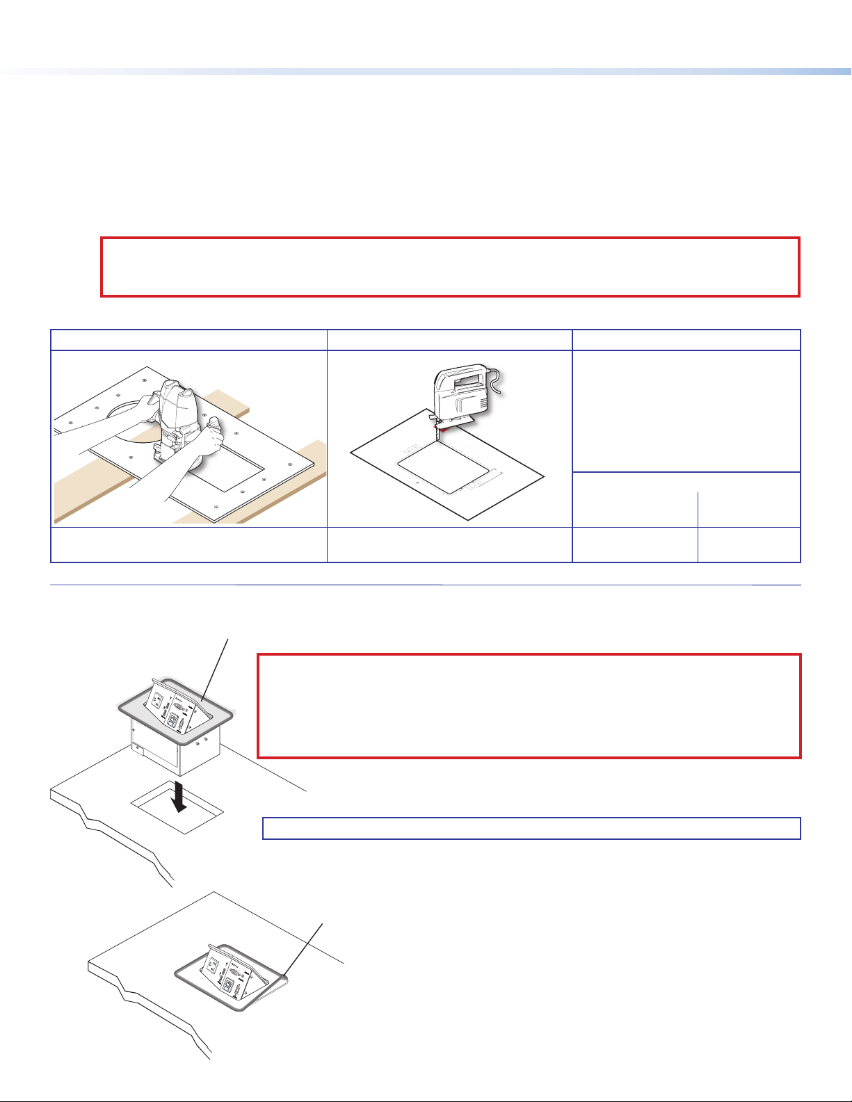
Choose one of the following methods for cutting the hole:
Hand router and routing template Jigsaw and paper cut-out template CNC wood router
If using a CNC wood router or other
Router
Visit www.extron.com for HSA routing
template part numbers and instructions.
Print this
template
at 100%
Cut-Out Template for Extron's
1. Confirm Product to be installed
2. Measure cutout and template
3. After checking, cut opening
HSA 300
+
0.00” (0.00 cm)
0.02 (0.05 cm)
User Access (Connectors and AAP Openings)
T
r
im Ring’s O
(Do not cut thi
uter Edge
s line.)
1.14”
0.25"
Trim Ring
Lip Width
Dimensions and print-out templates are
available online at www.extron.com.
precise machinery, use the exact
cut-out dimensions for your model
(see the table below).
Cut-out Dimensions
Width (user access
side)
7.68"
(19.50 cm)
Side
Dimension
5.88"
(14.93 cm)
Installing the HSA 300 in the Table
Remove the protective lm on the surface of the HSA enclosure. Do not remove
1
125V~ 50-60Hz
12A MAX
VGA
IN
2
the rubber strip that protects the edges of the enclosure until step 3, below.
CAUTION: The anged edges of the top of the surface enclosure are sharp. These edges are
also soft and may be easily nicked or bent. Exercise caution when handling the enclosure
to prevent personal injury or damage to the enclosure.
ATTENTION: Les extrémités à brides du haut de la surface du boîtier sont aiguisées. Ces
extrémités sont aussi lisses et peuvent facilement être coupées ou pliées. Soyez prudents
lorsque vous manipulez le boîtier an d’éviter de l’endommager ou de vous blesser.
Carefully lower the HSA enclosure into the hole to test the t.
2
NOTE: If necessary, remove the enclosure and enlarge or smooth the opening.
3
125V
~
50-60Hz
12A
MAX
VGA
IN
Insert the HSA fully into the hole so that the surface of the
4
enclosure is ush with the table.
Once the HSA is seated in the hole, carefully remove the
plastic strip that protects the edges of the enclosure.
Page 3

Unbalanced Output
RL
1
3
5
4
D
125
1
4
3
Once the HSA is seated in the hole, carefully remove the
plastic strip that protects the edges of the enclosure.
Insert the HSA fully into the hole so that the surface of the
enclosure is ush with the table.
2
Carefully lower the HSA enclosure into the hole to test the t.
Remove the protective lm on the surface of the HSA enclosure. Do not remove
the rubber strip that protects the edges of the enclosure until step 3, below.
VGA
IN
VGA
IN
125V~ 50-60Hz
12A MAX
125V
~
50-60Hz
12A
MAX
V~
50
6
0
Hz
1
2A
MA
X
V
G
A IN
7
Tighten the wing nuts on
Cabling
Step 1 - Connect Cables
Follow the steps below to cable the HSA 300 under the table.
A. DC power for USB — Connect the included external power
supply to this DC power input.
B. Audio — Wire this captive screw audio output as shown below.
the table clamps to lock
the clamps in position.
From the underside of the table, install
5
the table clamps on the enclosure at a
height at which the clamps will reach
the underside of the table.
Snugly tighten the Phillips head screws until the
6
table clamps reach the underside of the table.
ATTENTION: Do not overtighten the
Phillips head screws on the screw clamps.
Overtightening can bend the horizontal ange
of the screw clamp.
ATTENTION: Ne serrez pas trop les vis à tête
Phillips sur les pinces à visser. Le fait de trop
serrer peut faire se plier la xation horizontale
de la pince à vis.
A
B
C
C. HDMI output — Connect an HDMI cable from a display device to
this female HDMI connector.
D. VGA output — Connect a VGA cable from a display device to this
female VGA connector.
E. RJ-45 connector — Plug one end of a CAT 5 or CAT 6 twisted
pair (TP) cable into this RJ-45 female connector. Connect the
other end to an appropriate telecommunications or data network.
F. AC power input — Connect this cord to the power source.
Ring
Sleeve
Tip
Audio
NOTE: All RJ-45 connectors are terminated in accordance
with the TIA/EIA T568B standard.
NOTE:
• For the US version, this cord is permanently
connected to the HSA.
• For the EU and Multi-Region versions, this
IEC cord is removable.
E
F
HSA 300 - US version
3
Page 4

Icon Label
C
GF
Step 2 - Route and Organize Cables
Under the Table
NOTE: Make sure the lid of the HSA is open
while securing and routing the cables. If
the lid is closed during routing, the cables
attached to the front panel can restrict the
lid from opening.
If necessary, use zip ties to secure the
cables to the zip tie holes (see the image
at right).
Zip tie holes
ATTENTION: Allow approximately 1 inch of
cable length to protrude from the metal plate
before bending the cables for routing. The
cables can become damaged over time if they
are bent against the edges of the plate.
ATTENTION: Laissez dépasser les câbles
d’environ 2,54 centimètres (1 inch) au-dessous
de la plaque en métal avant de les plier. S’ils
sont pliés contre les bords de la plaque, les
câbles peuvent s’endommager au l du temps.
Front Panel Connectivity
A
B
The image at right shows the front panel of the HSA 300.
A. AC power outlet — Plug a standard power cord into this connector
to provide AC power for a laptop or other device. The power output
is the same voltage and frequency as the power input.
NOTE: The Multi-Region AC outlet is fully compatible with
125V 50-60Hz 12A MAX
Europlug, Indian, Danish, and Italian plug types. See the
Multi-Region AC Outlet Compatibility Guide on the Extron
website, www.extron.com, for compatibility details on all
plug types.
USB CHARGER
B. USB power LED — This LED lights green when power is available.
C. USB power outputs — Connect USB-powered devices for charging.
D. Computer video input — Plug the VGA-UXGA output from a
computer into this 15-pin HD female connector.
E. Audio input connector — Plug a 3.5 mm stereo plug into this jack for unbalanced audio input.
F. RJ-45 connector — Plug a CAT 5 or CAT 6 twisted pair (TP) cable into this RJ-45 female connector for network, data, or
communication connection.
NOTE:
• If necessary, on the front panel, replace the connector icon by prying the existing
icon off of the connector plug-in with a Tweeker and snapping the appropriate
icon in place (see the image at right).
• To change to a different color connector bezel, replace the connector bezel
plug-in on the front panel with a bezel of a different color. If a connector is not
needed, replace the connector bezel plug-in with a blank plug-in.
D
VGA IN AUDIO IN
E
HSA 300
HDMI IN
G. HDMI input — Connect an HDMI source device to this HDMI connector.
Extron Headquarters
+800.633.9876 Inside USA/Canada Only
Extron USA - West Extron USA - East
+1.714.491.1500 +1.919.850.1000
+1.714.491.1517 FAX +1.919.850.1001 FAX
© 2014 Extron Electronics All rights reserved. All trademarks mentioned are the property of their respective owners. www.extron.com
Extron Europe
+800.3987.6673
Inside Europe Only
+31.33.453.4040
+31.33.453.4050 FAX
Extron Asia
+65.6383.4400
+65.6383.4664 FAX
Extron Japan
+81.3.3511.7655
+81.3.3511.7656 FAX
4
Extron China
+86.21.3760.1568
+86.21.3760.1566 FAX
Extron
Middle East
+971.4.299.1800
+971.4.299.1880 FAX
Extron Korea
+82.2.3444.1571
+82.2.3444.1575 FAX
Extron India
1800.3070.3777
Inside India Only
+91.80.3055.3777
+91.80.3055.3737 FAX
68-2484-50
Rev. B
04 14
 Loading...