

Page 1

FOX SW8
8-Input Fiber Optic Switcher
User Guide
Fiber Optic Switchers
68-1550-02 Rev. B
04 13
Page 2
Safety Instructions
Safety Instructions • English
WARNING: This symbol, , when used on the product, is intended
to alert the user of the presence of uninsulated dangerous voltage
within the product’s enclosure that may present a risk of electric
shock.
ATTENTION: This symbol, , when used on the product, is intended
to alert the user of important operating and maintenance (servicing)
instructions in the literature provided with the equipment.
For information on safety guidelines, regulatory compliances, EMI/EMF
compatibility, accessibility, and related topics, see the Extron Safety and
Regulatory Compliance Guide, part number 68-290-01, on the Extron
website, www.extron.com.
Instructions de sécurité • Français
AVERTISSEMENT: Ce pictogramme, , lorsqu’il est utilisé sur le
produit, signale à l’utilisateur la présence à l’intérieur du boîtier
du produit d’une tension électrique dangereuse susceptible de
provoquer un choc électrique.
ATTENTION: Ce pictogramme, , lorsqu’il est utilisé sur le produit,
signale à l’utilisateur des instructions d’utilisation ou de maintenance
importantes qui se trouvent dans la documentation fournie avec le
matériel.
Pour en savoir plus sur les règles de sécurité, la conformité à la
réglementation, la compatibilité EMI/EMF, l’accessibilité, et autres sujets
connexes, lisez les informations de sécurité et de conformité Extron,
réf. 68-290-01, sur le site Extron, www.extron.fr.
Sicherheitsanweisungen • Deutsch
WARNUNG: Dieses Symbol auf dem Produkt soll den Benutzer
darauf aufmerksam machen, dass im Inneren des Gehäuses dieses
Produktes gefährliche Spannungen herrschen, die nicht isoliert sind
und die einen elektrischen Schlag verursachen können.
Chinese Simplified(简体中文)
警告: 产品上的这个标志意在警告用户该产品机壳内有暴露的危险
电 压 ,有 触 电 危 险 。
注意: 产品上的这个标志意在提示用户设备随附的用户手册中有
重要的操作和维护(维修)说明。
关于我们产品的安全指南、遵循的规范、
使用的特性等相关内容,敬请访问
安全规范指南,产品编号
68-290-01。
EMI/EMF 的兼容性、无障碍
Extron 网站 www.extron.cn,参见 Extron
Chinese Traditional(繁體中文)
警告: 若產品上使用此符號,是為了提醒使用者,產品機殼內存在著
可能會導致觸電之風險的未絕緣危險電壓。
注意 若產品上使用此符號,是為了提醒使用者。
有關安全性指導方針、法規遵守、EMI/EMF 相容性、存取範圍和相關主題的詳細
資訊,請瀏覽 Extron 網站:www.extron.cn,然後參閱《Extron 安全性與法規
遵守手冊》,準則編號 68-290-01。
Japanese
警告: この記 号 が製品上に表示されている場合は、筐体内に絶縁されて
いない高電圧が流れ、感電の危険があることを示しています。
注意: この 記号 が製品上に表示されている場合は、本機の取扱説明書に
記載されている重要な操作と保守 (整 備)の指 示についてユーザーの
注意を喚起するものです。
VORSICHT: Dieses Symbol auf dem Produkt soll dem Benutzer in
der im Lieferumfang enthaltenen Dokumentation besonders wichtige
Hinweise zur Bedienung und Wartung (Instandhaltung) geben.
Weitere Informationen über die Sicherheitsrichtlinien, Produkthandhabung,
EMI/EMF-Kompatibilität, Zugänglichkeit und verwandte Themen finden Sie
in den Extron-Richtlinien für Sicherheit und Handhabung (Artikelnummer
68-290-01) auf der Extron-Website, www.extron.de.
Instrucciones de seguridad • Español
ADVERTENCIA: Este símbolo, , cuando se utiliza en el producto,
avisa al usuario de la presencia de voltaje peligroso sin aislar dentro
del producto, lo que puede representar un riesgo de descarga
eléctrica.
ATENCIÓN: Este símbolo, , cuando se utiliza en el producto, avisa
al usuario de la presencia de importantes instrucciones de uso
y mantenimiento recogidas en la documentación proporcionada
con el equipo.
Para obtener información sobre directrices de seguridad, cumplimiento
de normativas, compatibilidad electromagnética, accesibilidad y
temas relacionados, consulte la Guía de cumplimiento de normativas
y seguridad de Extron, referencia 68-290-01, en el sitio Web de Extron,
www.extron.es.
安全上のご注意、法規厳守、EMI/EMF適合性、その他の関連項目に
つ い て は 、エ ク ストロ ン の ウ ェ ブ サ イト www.extron.jpより
『Extron Safety and Regulatory Compliance Guide 』 (P/N 68-290-01) をご覧くだ さい 。
Korean
경고: 이 기호 , 가 제품에 사용될 경우, 제품의 인클로저 내에 있는
접지되지 않은 위험한 전류로 인해 사용자가 감전될 위험이 있음을
경고합니다.
주의: 이 기호 , 가 제품에 사용될 경우, 장비와 함께 제공된 책자에 나와
있는 주요 운영 및 유지보수(정비) 지침을 경고합니다.
안전 가이드라인, 규제 준수, EMI/EMF 호환성, 접근성, 그리고 관련
항목에 대한 자세한 내용은 Extron 웹 사이트(www.extron.co.kr)의
Extron 안전 및 규제 준수 안내서, 68-290-01 조항을 참조하십시오.
Page 3

FCC Class A Notice
This equipment has been tested and found to comply with the limits for a Class A digital device,
pursuant to part15 of the FCC rules. The ClassA limits provide reasonable protection against harmful
interference when the equipment is operated in a commercial environment. This equipment generates,
uses, and can radiate radio frequency energy and, if not installed and used in accordance with the
instruction manual, may cause harmful interference to radio communications. Operation of this
equipment in a residential area is likely to cause interference; the user must correct the interference at
his own expense.
NOTE: For more information on safety guidelines, regulatory compliances, EMI/EMF
compatibility, accessibility, and related topics, see the “Extron Safety and
Regulatory Compliance Guide” on the Extron website.
Copyright
© 2013 Extron Electronics. All rights reserved.
Trademarks
All trademarks mentioned in this guide are the properties of their respective owners.
The following registered trademarks®, registered service marks
AVTrac, Cable Cubby, CrossPoint, eBUS, EDID Manager, EDID Minder, Extron, Flat Field,GlobalViewer, Hideaway, Inline, IP Intercom, IP Link, Key
Minder, LockIt, MediaLink, PoleVault, PURE3, Quantum, SoundField, System Integrator, TouchLink, V-Lock, VersaTools, VN-Matrix, VoiceLift,
WallVault, WindoWall
Registered Service Mark
AAP, AFL (Accu-Rate Frame Lock), ADSP (Advanced Digital Sync Processing), AIS (Advanced Instruction Set), Auto-Image, CDRS (Class D Ripple
Suppression), DDSP (Digital Display Sync Processing), DMI (Dynamic Motion Interpolation), Driver Configurator, DSP Configurator, DSVP (Digital
Sync Validation Processing), FastBite, FOXBOX, IP Intercom HelpDesk, MAAP, MicroDigital, PowerCage, ProDSP, QS-FPC (QuickSwitch Front
Panel Controller), Scope-Trigger, SIS, Simple Instruction Set, Skew-Free, SpeedMount, SpeedNav, SpeedSwitch, Triple-Action Switching, XTP, XTP
Systems, XTRA, ZipCaddy, ZipClip
(SM)
: S3 Service Support Solutions
(SM)
, and trademarks
Registered Trademarks
(TM)
are the property of RGB Systems, Inc. or Extron Electronics:
Trademarks
(®)
(™)
Page 4
Specifications Availability
Product specification are available on the Extron website, www.extron.com.
Conventions Used in this Guide
Notifications
The following notifications are used in this guide:
WARNING: A warning indicates a situation that has the potential to result in death or
severe injury.
CAUTION: A caution indicates a situation that may result in minor injury.
ATTENTION: Attention indicates a situation that may damage or destroy the product or
associated equipment.
NOTE: A note draws attention to important information.
Software Commands
Commands are written in the fonts shown here:
^AR Merge Scene,,Op1 scene 1,1 ^B 51 ^W^C
[01] R 0004 00300 00400 00800 00600 [02] 35 [17] [03]
E X! *X1@* X1%* X1** X1^ CE}
NOTE: For commands and examples of computer or device responses mentioned
in this guide, the character “0” is used for the number zero and “O” is the capital
letter “o.”
Computer responses and directory paths that do not have variables are written in the font
shown here:
Reply from 208.132.180.48: bytes=32 times=2ms TTL=32
C:\Program Files\Extron
Variables are written in slanted form as shown here:
ping xxx.xxx.xxx.xxx —t
SOH R Data STX Command ETB ETX
Selectable items, such as menu names, menu options, buttons, tabs, and field names are
written in the font shown here:
From the File menu, select New.
Click the OK button.
Page 5

Contents
Introduction............................................................ 1
About this Guide ................................................. 1
About the FOX SW8 ........................................... 1
Features ............................................................. 3
Installation and Operation .................................. 4
Rear Panel Connections ..................................... 4
Front Panel Configuration Port ............................ 7
Controls, Indicators, and Operation .................... 7
Controls and Indicators ................................... 7
Button Icons ................................................... 7
Operation ....................................................... 8
Remote Control ..................................................... 9
Remote Control Ports ......................................... 9
Simple Instruction Set Control ............................ 9
Host-to-interface Communications ................. 9
Start-up Message ........................................... 9
Error Responses ........................................... 10
Timeout ........................................................ 10
Using the Command and Response Table .... 10
Universal Switcher Control Program ................. 12
Installing the Software ................................... 12
Using the Program ........................................ 13
Firmware Upgrade ........................................ 15
Using the Help System ................................. 18
Button Label Generator Program ...................... 18
Location of Software on the Website ............ 19
Using the Button Label Generator Software .. 19
Reference Information ...................................... 20
Button Labels ................................................... 20
Installing Labels in the Switcher Buttons ....... 20
Mounting the Unit ............................................. 22
Tabletop Use ................................................ 22
Mounting kits ................................................ 22
Rack-Mounting UL Guidelines ...................... 22
vFOX SW8 • Table of Contents
Page 6

Page 7
Introduction
The topics covered in this section are:
• About this Guide
• About the FOX SW8
• Features
WARNING: Risk of serious physical injury: The FOX SW8 outputs continuous
invisible light, which may be harmful to the eyes; use with caution.
• Do not look into the rear panel fiber optic cable connectors or into the fiber optic
cables themselves.
• Plug the attached dust caps into the optical transceivers when the fiber cable is
unplugged.
About this Guide
This guide contains information about two models of Extron FOX SW8 ultra-high
performance fiber optic switchers.
NOTE: Many products are compatible with the FOX SW8. They will be identified where
About the FOX SW8
The FOX SW8 is available in two transmission modes, singlemode and a multimode, which
define the transmission range of the switcher:
• FOX SW8 MM — An 8-input, 1-output multimode switcher, with a range of up to
2000m (6561 feet) on each input and the output
• FOX SW8 SM — An 8-input, 1-output singlemode switcher, with a range of up to
30km (18.75 miles) on each input and the output
The switcher accepts up to eight proprietary input optical signals from compatible
Extron fiber optic transmitters (Txs) (see figure 1, on the next page). The optical signal can
include video, audio, and one-way (transmitter-to-receiver [Rx]) RS-232 communications.
Seven of the inputs are looped through and output for local use.
appropriate, but not specifically described in this guide.
NOTES:
• The multimode and singlemode switchers are physically and functionally
identical with the exception of the effective range of transmission.
In this guide, the terms “FOX SW8” and “switcher” refer to a switcher of either
transmission mode.
• The FOX SW8 MM and the FOX SW8 SM are not interchangeable.
FOX SW8 • Introduction 1
Page 8
Extron
Extron
FOX 500 Tx
Fiber Optic
Transmitter
FOX SW8
Fiber Optic
Switcher
RGB INPUT
R G B
100-240V 0.3A
50-60Hz
H V
FOX 500 Tx
RS-232
OPTICAL
LINK
PASS THRU
1 2*
LINK
Tx Rx NA
ALARM
OPTIONAL FOR
*
RS-232
RETURN DATA
CONTROL
1 2
R
Tx Rx
AUDIO INPUTS
L
INPUT LOOP THRU
RGB
OR
PC (RGB)
with Audio
100-240V 0.3A
50/60 Hz
Local
Monitor
1
LOOP IN
Figure 1. Typical FOX SW8 Application
OUT IN
LOOP IN
LOOP IN
OUTPUT
OPTICAL INPUTS
LOOP IN
4 5 6 7 8
LOOP IN
3
LOOP IN
2
LOOP IN
Extron
FOX 500 DVI Tx
Fiber Optic Transmitter
Extron
FOXBOX Tx VGA
Fiber Optic Transmitter
Extron
SI 26X
CLASS 2 WIRING
DO NOT GROUND
OR SHORT
SPEAKER OUTPUTS!
INPUTS
L
R
DVI-D INPUT
Local
Monitor
4/8
OUTPUT
OHMS
R
L
REMOTE
VOL/MUTE
10V 50mA
R
ALARM
RS-232
OVER FIBER
AUDIO
1 2
Tx Rx
FOXBOX Tx DVI
Two-Way Ceiling
Speakers
Projector
Laptop (DVI)
with Audio
Extron
MPA 152
DVI-D OUTPUT
MODE
FOXBOX Rx DVI Plus
POWER
12V
1.0A MAX
2*
LINK
Extron
FOXBOX Tx DVI
Fiber Optic Transmitter
Mini Power
Amplier
ALARM
RS-232
OVER FIBER
AUDIO
1 2
Tx Rx
PC (DVI)
with Audio
MPA 152
US
C
LISTED
17TT
AUDIO/VIDEO
APPARATUS
POWER
L
12V
3A MAX
POWER
12V
1.0A MAX
FOX SW8
RS-232
TxRx
Extron
FOXBOX Rx DVI Plus
Fiber Optic Receiver
FOX 500 DVI Tx
RS-232
OPTICAL
PASS THRU
1
NA
LINK
Tx Rx
ALARM
OPTIONAL FOR
*
RS-232
RETURN DATA
CONTROL
1 2
R
Tx Rx
AUDIO INPUTS
L
DVI-D
LOOP - THRU
100-240V 0.3A
50-60Hz
DVI-D INPUT
Laptop (RGB)
with Audio
ALARM
RS-232
OVER FIBER
AUDIO
1 2
Tx Rx
RGB INPUT
FOXBOX Tx VGA
POWER
12V
1.0A MAX
NOTES:
• Compatible optical signals are digital signals from 2.0 Mbps through 4.25 Gbps
that are sent and received via fiber optic SFP modules.
• The video component of the signal from an Extron Tx can be either VGA - UXGA
RGB video, Digital Visual Interface (DVI) or High-Definition Multimedia Interface
(HDMI) video, or SDI/HD-SDI video.
• The serial component of the signal is for applications such as projector control and
transmitter control of the receiver.
The switcher selects among the proprietary signal inputs and outputs the selected signal on
a fiber optic cable to a compatible receiver.
NOTES:
• The FOX SW8 does not support transmission of a return (Rx-to-Tx) serial data
stream.
• The switcher is compatible with most Extron FOX, FOXBOX, and PowerCage FOX
models. The switcher is not compatible with the DFX 100 and HFX 100 Extender
models.
The connected receivers convert the proprietary signals back to video (RGB, DVI, or
SDI/HD-SDI, depending on the source transmitter and the receiver), audio, and serial
RS-232 communication, and output the signals locally. For video resolutions up to
1900x1200, the video outputs for the receivers are a perfect, pixel-for-pixel or digital
recreation of the video signal input to the switcher via a transmitter.
FOX SW8 • Introduction 2
Page 9

Features
Ultra high performance — The switcher inputs up to eight perfect, pixel-by-pixel RGBHV
or digital video signals and transmits the selected signal to a compatible receiver. The
switcher can handle analog video resolutions up to 1900x1200 at 60 Hz. Higher resolutions
can be transmitted, but with some loss of video quality.
Optical input and outputs — The switcher inputs and outputs the optical signal on
LCvideo connectors.
Active and individually isolated inputs
System video output — When the optical input is from a FOX 500 or FOXBOX Tx, rather
than a FOX HD-SDI, the video portion of the optical video output can be decoded to either
RGB video or DVI video, depending on the receiver connected.
HDCP compliant — In an HDMI system, when two fiber cables are connected between
the input device and the switcher and between the switcher and the output device, the
switched signal maintains HDCP compliance.
NOTE: In an HDCP-compliant configuration, the input 8 fiber cable must be connected
to the output device, so the switcher is effectively a 7-input switcher (see figure 4, on
page 6).
Selectable output reclocking — Reshapes and restores timing of the digital signal on the
switched output at rate a selected among 4.25 Gbps, 2.125 Gbps, or 1.25 Gbps. You can
also bypass the reclocking function.
Loop through — Inputs 1 through 7 are looped through and available for local use or for
HDCP compliance.
NOTE: Loop through outputs are not reclocked.
Front panel USB configuration port — The FOX SW8 features a front panel USB port
that provides easy access for remote control operation.
RS-232 control — The FOX SW8 features a rear panel RS-232 serial port for remote
control operation.
Rack mounting — The unit is rack mountable in any conventional 19-inch wide rack, using
an Extron full size rack shelf.
Power — The 100 VAC to 240 VAC, internal power supply provides worldwide power
compatibility.
FOX SW8 • Introduction 3
Page 10

Installation and Operation
The topics covered in this section are:
• Rear Panel Connections
• Front Panel Configuration Port
• Controls, Indicators, and Operation
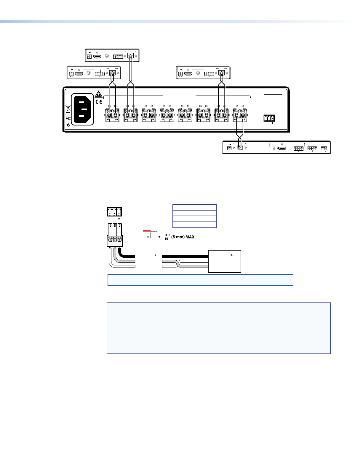
Rear Panel Connections
2 2222
100-240V 0.3A
12345678
LOOP IN LOOP IN LOOP IN LOOP IN LOOP IN LOOP IN LOOP IN OUTIN
2
OPTICAL INPUTS
2
2
FOX SW8
RS-232
50/60 Hz
1 3 4
3 3
3 3
3 3
Tx Rx
5
Figure 2. FOX SW8 Connectors
WARNING: Risk of serious physical injury: The FOX SW8 outputs continuous
invisible light, which may be harmful to the eyes; use with caution.
• Do not look into the rear panel fiber optic cable connectors or into the fiber optic
cables themselves.
• Plug the attached dust caps into the optical transceivers when the fiber cable is
unplugged.
NOTES:
• Singlemode and multimode devices are not interchangeable. Ensure that the
connected transmitting and receiving devices are compatible with the FOX SW8.
• Ensure that you use the proper fiber cable for your system. Typically, singlemode
fiber has a yellow jacket and multimode cable has an orange or aqua jacket.
• In this guide, the term “sending connector” refers to an LC connector on a device
that outputs a fiber optic signal. The term “receiving connector” refers to an LC
connector that receives an optical signal.
a AC power connector — Plug a standard IEC power cord into this connector to
connect the FOX SW8 to a 100 VAC to 240 VAC, 50-60 Hz power source.
FOX SW8 • Installation and Operation 4
Page 11
Transmitter
Transmitter
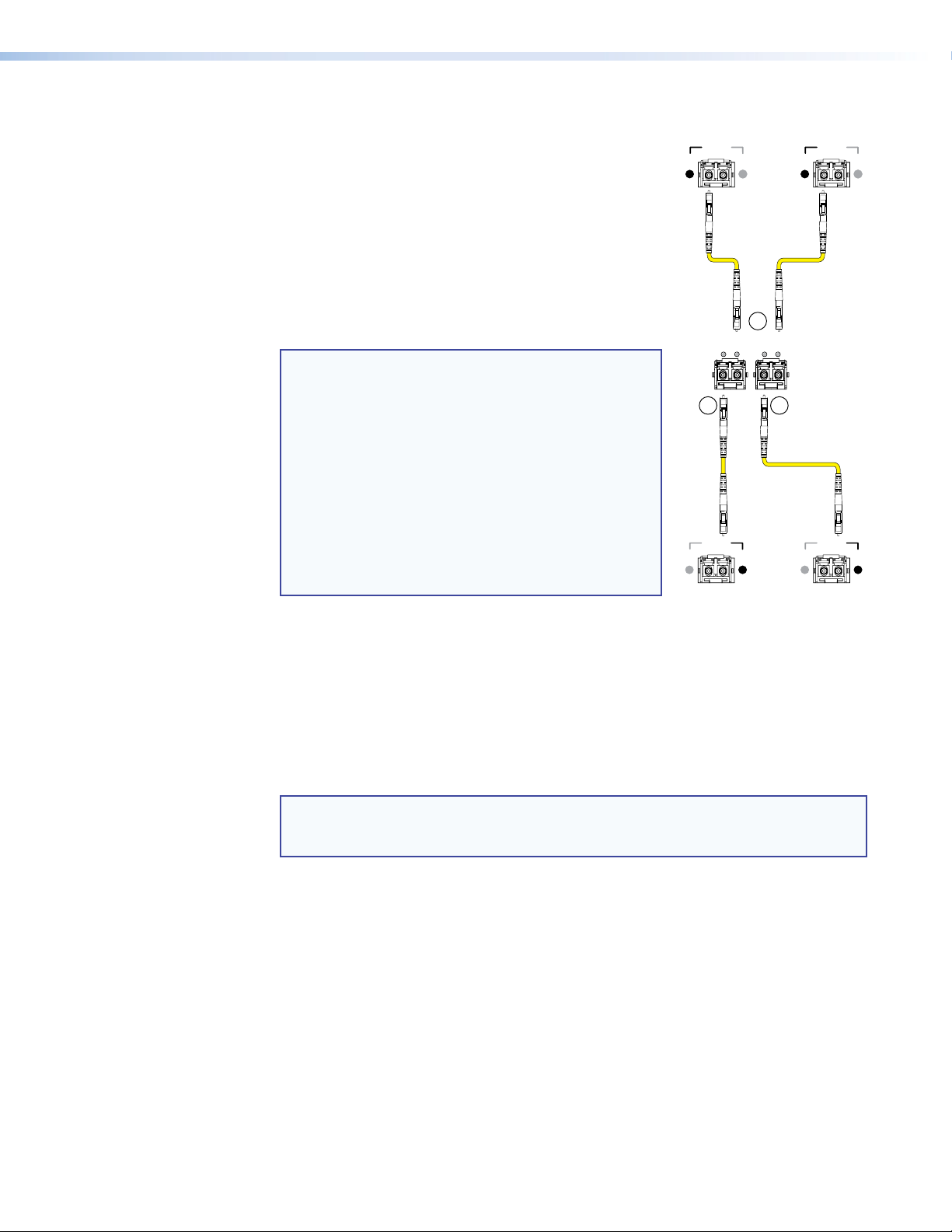
b Input connectors and LEDs —
Connectors — For one-way video, audio, and serial
communications from the transmitter to the FOX SW8
LINK
#7
Rx
Tx
LINK
(to be switched to the receiver) connect up to eight fiber
optic cables to the input (right-hand) LC connector on the
optical transceiver blocks (see figure 3).
Connect the far end of these fiber optic cables to
the sending connectors on the transmitters or other
compatible Extron devices.
LEDs — When lit, the link is active (light is received from
the transmitter).
2
78
LOOP IN OUTIN
NOTES:
• The right-hand LEDs for transceiver blocks 2, 4,
6, and 8 may light, but do not indicate an input
3
to that connector.
• For HDCP compliance when the output is to
an Extron FOXBOX or PowerCage FOX HDMI
receiver, connect a fiber cable between this
connector and the Tx LC connector on the
receiver.
• In an HDCP compliant system, input 8
cannot be from an active transmitter
(see figure 4 on the next page).
c Loop connectors and LEDs —
Connectors — For unswitched (input
Local (Loop)
Application
Figure 3. Inputs and Loop and
Receivers
Rx
Tx
LINK
LINK
Switched Outputs
1 loops through to output 1, input 2 to
output 2, and so on), one-way video, audio, and serial communications, looped
through from the switcher, connect fiber optic cables to the Loop
(left-hand) LC connectors on transceiver blocks 1 through 7 (see figure 3).
Connect the far ends of these fiber optic cables to the receiving connectors on the
receivers or other compatible Extron devices.
#8
Tx
LINK
Switcher
4
Tx
LINK
Switched
Application
Rx
LINK
Rx
LINK
NOTE: For HDCP compliance when the input is from an Extron FOXBOX or
PowerCage FOX HDMI transmitter, connect a fiber cable between this connector
and the Rx LC connector on the transmitter (see figure 4 on the next page).
LEDs — These LEDs are always lit (light is always output to these connectors).
d Output connector and LED —
Connector — For the switched output one-way video, audio, and serial
communications, connect a fiber optic cable to the Output (left-hand) LC connector on
transceiver block 8 (see figure 3).
Connect the far end of this fiber optic cable to the receiving connector on the receiver or
other compatible Extron device.
LED — This LED is always lit (light is always output on this connector).
FOX SW8 • Introduction 5
Page 12
FOXBOX Tx HDMI #2
POWER
FOXBOX Tx HDMI
12V
1.0A MAX
AUDIO INPUT
HDMI INPUT
POWER
FOXBOX Tx HDMI
12V
1.0A MAX
HDMI INPUT
AUDIO INPUT
RS-232
OVER FIBER
Tx Rx 1 2
ALARM
FOXBOX Tx HDMI #1
100-240V 0.3A
RS-232
OVER FIBER
Tx Rx 1 2
RxTx
LINK
OPTICAL
RxTx
ALARM
LINK
LINK
OPTICAL
LINK
Transmitters 3 — 6
• • • • • • •
POWER
12V
1.0A MAX
HDMI INPUT
FOXBOX Tx HDMI
AUDIO INPUT
RS-232
OVER FIBER
Tx Rx 1 2
RxTx
ALARM
LINK
LINK
OPTICAL
FOXBOX Tx HDMI #7
12345678
LOOP IN LOOP IN LOOP IN LOOP IN LOOP IN LOOP IN LOOP IN OUTIN
OPTICAL INPUTS
FOX SW8
RS-232
FOXBOX Rx HDMI
Tx Rx
HDMI AUDIO
OUTPUTS
AUDIO
RS-232
OVER FIBER
Tx Rx 1 2
REMOTE
RS-232
ALARM
Tx Rx
ON
OFF
LR
HDMI
50/60 Hz
POWER
12V
1.0A MAX
RxTx
LINK
LINK
OPTICAL
FOXBOX Rx HDMI
Figure 4. HDCP-Compliant Configuration
e RS-232 port — For serial control of the switcher, connect a host device, such as a
computer, touch panel control, or RS-232 capable PDA, via this 3-pole captive screw
connector (see figure 5 to wire this connector).
RS-232
Tx Rx
Do not tin the wires!
Ground ( )
Bidirectional
Receive (Rx)
Transmit (Tx)
NOTE: Cross the Tx and Rx lines once between the source and the target.
FunctionPin
Tx
Transmit data
Rx
Receive data
Gnd
Signal ground
Controlling
Device
Ground ( )
Receive (Rx)
Transmit (Tx)
Figure 5. RS-232 Connectors
NOTES:
• The length of exposed wires is critical. The ideal length is 3/16 inches (5 mm).
• If the stripped section of wire is longer than 3/16 inches, the exposed wires
may touch, causing a short circuit.
• If the stripped section of wire is shorter than 3/16 inches, wires can be easily
pulled out even if tightly fastened by the captive screws.
This port is RS-232 only, with the following protocols:
• 9600 baud • no parity • 8 data bits
• 1 stop bit • no flow control
FOX SW8 • Introduction 6
Page 13
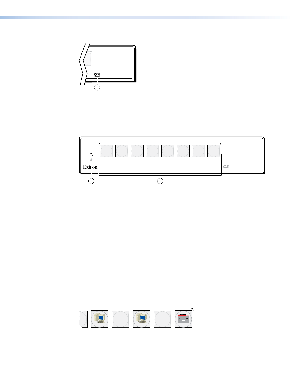
Front Panel Configuration Port
INPUTS
8
CONFIG
FOX SW SERIES
FIBER OPTIC SWITCHER
1
Figure 6. FOX SW8 Configuration Port
a Config(uration) port — For USB control of the switcher, connect a host device, such
as a computer or touch panel control, via this mini USB B port.
Controls, Indicators, and Operation
INPUTS
6 7 854321
CONFIG
FOX SERIES
FIBER OPTIC SWITCHER
1 2
Figure 7. FOX SW8 Front Panel
Controls and Indicators
a Power LED — This LED lights when power is applied to the unit.
Button Icons
b Input Buttons — These buttons select the input. A button lights to indicate the
selected input.
The numbered translucent covers on the input and output buttons can be removed and
replaced to insert labels behind the covers.
Labels can be created easily with the Extron Button Label Generator software,
which ships with the switcher. Each input can be labeled with names, alphanumeric
characters, or even color bitmaps for easy and intuitive input selection (see
figure 8 for sample button icons, Button Label Generation Program on page 18 for using
the labeling software, and Button Labels on page 20 for blank labels and a procedure for
removing and replacing the translucent covers).
Computer Computer
75
VTG 200
Figure 8. Sample Button Icons
FOX SW8 • Introduction 7
Page 14

Operation
After the transmitters, the switcher, the receivers (for the looped out and selected optical
signals), and their connected devices are powered up, the system is fully operational. Select
an input by pressing the desired input button. The button lights to indicate the selected
input.
NOTE: The switcher can take up to 6 minutes to save an input selection, a front panel
lock, or selection of background illumination. Wait at least 6 minutes after one of
these operations before removing power or the settings may be lost.
If any problems are encountered, ensure all cables are routed and connected properly:
• Ensure that the video sources and the displays are properly connected to the
transmitters, the switcher, and the receivers, and that all equipment has power applied.
• Ensure that the rear panel Input signal monitoring LEDs (see item b on page 5) are
indicating correctly for your system configuration.
NOTE: If problems persist, call the Extron S3 Sales and Technical Support Hotline
(see the last page of this guide for the phone number in your region of the world).
Front panel lockout (executive mode)
The front panel lockout prevents the operation of the switcher from the front panel. If you try
to select an input when the front panel is locked, all of the input buttons flash once and the
input selection remains unchanged.
To toggle the front panel lock on or off, press and hold the Input 7 and Input 8 buttons
simultaneously for approximately 3 seconds, until all of the input buttons flash three times.
System reset
The switcher can be reset from the front panel to:
• Unmute the switched output (which can be muted under serial port control only).
• Unlock the front panel.
• Select input 1 for output.
To reset the switcher, press and hold the Input 1 button while you apply power to the
switcher. The input buttons blink red, green, red, amber, and go out. Input 1 is selected (the
Input 1 button is lit).
Background illumination
The buttons on the front panel can be set to provide amber background illumination at
all times or the background illumination can be turned off. To toggle the background
illumination on or off, press and hold the Input 1 and Input 2 buttons simultaneously for
approximately 3 seconds.
FOX SW8 • Introduction 8
Page 15

Remote Control
The topics covered in this section are:
• Remote Control Ports
• Simple Instruction Set Control
• Universal Switcher Control Program
• Button Label Generator Program
Remote Control Ports
The switcher has two ports that can be connected to a host device such as a computer
running the Extron DataViewer utility or the HyperTerminal utility, an RS-232 capable PDA, or
a control system. These ports make remote control of the switcher possible. The ports are:
• The rear panel RS-232 port — This is a 3-pin captive screw connector (see item e
on page 6).
• The front panel Config(uration) port — This is a mini USB B port (see item a on
page 7). This port requires the Extron DataViewer utility (version 2.0 or newer) for
communications.
NOTE: Before you use the USB port for the first time, you need to install and
activate the USB driver on your computer. The simplest way to do this is to install
version 4.1 or newer of the Universal Switcher Control Program and then run the
Found New Hardware Wizard. See Installing the Software on page 12 and
Activating a USB port for the first time on page 13.
Simple Instruction Set Control
Host-to-interface Communications
The Extron Simple Instruction Set (SIS) commands consist of one or more characters per
field. No special characters are required to begin or end a command character sequence.
When a command is valid, the unit executes the command and sends a response to the
host device. All responses from the unit to the host end with a carriage return and a line
feed (CR/LF = ]), which signals the end of the response character string. A string is one or
more characters.
Start-up Message
The switcher issues the following copyright message when it first powers on. 20yy is the
year, Vx.xx is the firmware version number, and 60-1171-xx is the part number.
(C) COPYRIGHT 20yy, EXTRON ELECTRONICS FOX SW8 SM (or MM),Vx.xx, 60-1172-xx]
FOX SW8 • Remote Control 9
Page 16

Error Responses
When the unit receives a valid SIS command, it executes the command and sends a
response to the host device. If the unit is unable to execute the command because the
command is invalid or it contains invalid parameters, the unit returns an error response to
the host. The error response codes are:
E10 — Invalid command
E12 — Invalid output number
E13 — Invalid range
E22 — Busy
Timeout
Pauses of 10 seconds or longer between command ASCII characters result in a timeout.
The command operation is aborted with no other indication.
Using the Command and Response Table
The Command and Response Table for SIS Commands is on page 11. Commands in
the table are NOT case sensitive. The ASCII to HEX conversion table, below, is for use with
the command and response table.
ASCII to Hex Conversion Table
Space
•
Symbol Definitions
Symbols (variables), defined below, are used in the command and response table. The
symbols represent variables in the command and response table fields.
] = Carriage return/line feed
} = Carriage return (no line feed)
E = <Escape> key (hex 1B)
• = Space (hard) character
W = Can be used interchangeably with the E character
= Can be used interchangeably with the } character
|
X! = Input 00 through 08 (00 = no input)
X@ = Mute/front panel lock status 0 = off (unmuted/unlocked) 1 = on (muted/locked)
X# = Transceiver module status 0 = no module installed
1 = multimode 2 = singlemode
X$ = Firmware version v.vv
X% = Transceiver module status 0 = no light input 1 = light input
X^ = Temperature nnnF = whole degree Fahrenheit
X& = Input reclocker rate 00 = Bypass (no reclocking) 02 = 2.125 Gbps
01 = 1.25 Gbps 03 = 4.25 Gbps (default)
X* = Name Up to 24 upper- and lower-case alphanumeric characters. Hyphen characters
are valid, blank and space characters are invalid. The first character must be a
letter. The last character may not be a hyphen.
FOX SW8 • Remote Control 10
Page 17
Command and Response Table for SIS Commands
Command Function
ASCII Command
(Host to Unit)
Response
(Unit to Host)
Additional description
Input selection
NOTE: The three command codes in the input selection commands and view input commands; !, &, and %; can be used
interchangeably.
Select input
Select input
Select input
View input
View input
View input
X!
! InX!•All
X!
& InX!•RGB
X!
% InX!•Vid
!
&
%
X!]
X!]
X!]
]
]
]
Select input X! to output.
Select input X! to output.
Select input X! to output.
Input X! is selected for output.
Input X! is selected for output.
Input X! is selected for output.
Channel mute
WARNING: Risk of serious physical injury: The channel mute command mutes the data on the switched output only. The output
continues to emit light, which may be harmful to the eyes. The mute function has no affect on the looped-through outputs.
Mute output
Unmute output
Show video mute status
1B
0B
B
Vmt1
Vmt0
X@]
]
]
Blank data on switched output.
Output data on switched output.
Switched output mute status is X@.
Reclocking
Set reclocker mode
Example:
Example:
Show reclocker mode
08*X&= Rte08*
08*0=
08*0=
08=
X&]
Rte08*00
Rte08*03
X&]
]
]
Set the reclocker mode to X&.
Set the output reclocker mode to bypass (do not reclock).
Set the output reclocker mode to 4.25 Gbps (default).
Front panel security lockout (executive mode)
Lock front panel
Unlock front panel
Show lock status
1
0X
X
X
Exe1
Exe0
X@]
]
]
Inputs cannot be selected from the front panel.
Inputs can be selected from the front panel.
Front panel lock status is X@.
Resets
Reset mute
Reset whole switcher
Information Requests and Unit Name
Information request
Show firmware version
Example:
Request part number
Show input connections
status
Show temperature
Show transceiver module
status
Set switcher name
Example:
Set switcher name to
factory default
View switcher name
EZZ}
E
I
Q
Q
N
0LS
20S
0*1I
ZXXX
}
EX*CN}
E
Switcher_1CN
E
}
•CN
}
ECN} X*]
Zpz
Zpx
In
X!
]
]
•Vmt
X@]
Unmute the output.
Unmute the output, unlock the front panel, and select
input 1.
InX! indicates the selected input. VmtX@ indicates the
output mute status (
X$] X$
]
1.23
60-1172-nn
X%1X%2X%3X%
]
4
X%8]
...
The factory-installed FOX SW8 controller firmware
version is 1.23 (sample value only).
nn indicates the transmission mode.
01 = multimode, 02 = singlemode.
Each X% indicates the status of an input,
0 = no light on this input, 1 = light received.
X^] X^
X*]
4
...
X#8]
]
Show all installed transceiver modules.
0 = none, 1 = multimode, 2 = singlemode.
Set the switcher name to X*.
]
Set the switcher name to “Switcher-1”.
Restore the factory default name.
X#1X#2X#3X#
Ipn•
Ipn•Switcher-1
Ipn•FOX-SW8
0 = unmuted, 1 = muted)..
is the firmware version.
= degrees Fahrenheit.
FOX SW8 • Remote Control 11
Page 18

Universal Switcher Control Program
The Extron Universal Switcher Control Program, which communicates with the switcher via
the rear panel RS-232 port or front panel Configuration port of the unit, provides an easy
way to configure and operate the FOX SW8 switcher.
The program is compatible with Windows 2000, Windows XP, Windows 7, and newer
Windows operating systems. Updates to this program can be downloaded from the Extron
website (www.extron.com).
Installing the Software
The program is contained on the Extron Software Products DVD. Install the software as
follows:
1. Insert the DVD into the drive. The installation program should start automatically. If it
does not self-start, run Launch.exe from the DVD.
2. The Extron software DVD window appears (see figure 9).
Figure 9. Software DVD Window
3. Click the Software tab (see figure 9).
4. Scroll to the desired program and click Install (see figure 10).
Figure 10. Software Installation
5. Follow the on-screen instructions. By default, the installation of the Universal Switcher
Control Program creates the folder C:\Program Files [or Program Files (x86) for
32-bit versions of Windows 7]\Extron\UniversalSwitcher, and it places four icons
into a group folder named Extron Electronics\Universal Switcher:
• Check for Universal Switcher Updates
• Uninstall Universal Switcher
• Universal Switcher Help
• Universal Switcher Control Program
FOX SW8 • Remote Control 12
Page 19

Using the Program
NOTE: The first time you connect to the Configuration (USB) port, the Found New
Hardware Wizard appears (see figure 11). See “Activating a USB port for the first
time,” below.
For other connections, proceed to “Starting the program,” below.
1
1
2
2
Figure 11. Found New Hardware Wizard
Activating a USB port for the first time
The first time you connect to the Configuration (USB) port, the Found New Hardware Wizard
appears (figure 11). Activate the connected USB port for your device as follows:
NOTE: If you have not installed the latest Universal Switcher Control Program
(version 4.1 or newer), click Cancel, install the program, and reboot the PC.
Reconnect the computer to the Configuration port on the switcher.
6. Select the No, not this time radio button and click Next.
7. Select the Install the software automatically radio button and click Next.
Follow the on-screen instructions. The wizard assigns the driver necessary to access
the switcher to the connected Configuration (USB) port (this may take a few minutes).
8. Click Finish to exit the wizard.
9. Proceed to “Starting the program,” below, or return to the Simple Instruction Set
Control section on page 9.
NOTE: You may need to repeat these steps if you subsequently connect the
switcher to a different USB port on the same computer.
Starting the program
Start the program as follows:
1. Connect a computer that runs the Windows® operating system to either the RS-232
port of the switcher (see item e on page 6) or the Configuration port (see item a on
page 7).
2. Click Start > Programs > Extron Electronics > Universal Switcher >
Universal Switcher Control Program
The Communication Setup window appears (see figure 12, on the next page).
.
FOX SW8 • Remote Control 13
Page 20

Figure 12. Communication Setup Window
3. If necessary, select the tab, RS-232 or USB, for the port you are using for the
connection.
4. Depending on the tab that is selected, RS-232 or USB, select either:
• RS-232 tab — The Com port to which your switcher is connected
• USB tab — Extron USB Device_0
5. Click Connect. The Extron Universal Switcher Control Program window (see figure 13)
displays the selected video and audio input.
Figure 13. Universal Switcher Control Program Window
FOX SW8 • Remote Control 14
Page 21

6. Operate the switcher as follows:
• To select an input, click the associated input button.
• To mute the output, click the Mute Video checkbox.
• To toggle the front panel lock on and off, click the Lock button ( ).
• To bypass output reclocking or to select a data rate at which to reclock the
Firmware Upgrade
Firmware can be upgraded via the front panel Configuration port of the unit only, using the
Extron Firmware Loader utility from the Universal Switcher Control Program.
Upload replacement firmware as follows:
1. Visit the Extron website, www.extron.com, click the Download tab, and then click the
Firmware link (see figure 14).
WARNING: Risk of serious physical injury: The mute video checkbox
mutes the data on the switched output only. The output continues to emit
potentially dangerous laser light. The mute function has no affected on the
looped-through outputs.
output, roll the mouse over the Reclock Setting tab and then use the resultant
drop-down menu.
1
NOTE: The name, version and
1
file size shown are
sample values only.
2
3
3
Figure 14. Location of Firmware Upgrade Files
2. Select the appropriate firmware file (FOX SW8) to download and click Download.
3. Enter the requested personal information and then click Download to copy the firmware
to your computer.
FOX SW8 • Remote Control 15
Page 22

4. Click Run on the next two screens (see figure 15). The PC downloads the firmware
update from the Extron website and starts the Extron Installation Program to extract the
firmware file.
NOTE: The name, version and
4
4
file size shown are
sample values only.
5
Folder where
firmware is
installed
6
Figure 15. Downloading Firmware Upgrade Files
FOX SW8 • Remote Control 16
Page 23

5. Click Next. The program extracts the firmware files and places them in a folder
identified in the InstallShield Wizard window.
NOTE: Note the folder to which the firmware file is saved.
6. Click Finish to exit the program.
7. Connect a computer that runs the Windows operating system to either the RS-232 port
or the Configuration port of the switcher (see Installation and Operation on page 4
for more details).
8. Start the Universal Switcher Control Program and connect to the front panel
Configuration (USB) port on the switcher (see Starting the program, on page 13).
9. Click Tools > Update firmware or the Update Firmware button ( ). The Extron
Firmware Loader appears (see figure 16).
10
Figure 16. Extron Firmware Loader Window
10. Select the FOX SW8 and click File > Open. The Choose Firmware File screen appears
(see figure 17).
11
11
Figure 17. Choose Firmware File Window
11. Navigate to and select the new firmware file. Click Open. The Choose Firmware File
window closes.
ATTENTION: The firmware file must have an .S19 extension. Other file types can
cause the switcher to stop functioning.
FOX SW8 • Remote Control 17
Page 24

NOTES:
• When downloaded from the Extron website, the firmware is placed in a
subfolder of C:\Program Files\Extron\Firmware.
• Valid firmware files must have the file extension .S19. A file with any other
extension is not a firmware upgrade.
• The original factory-installed firmware is permanently available on the switcher.
If the attempted firmware upload fails for any reason, the switcher reverts to
the factory-installed firmware.
12. In the Firmware Loader window, click Begin (see figure 18).
The Total Progress and Progress status bars show the upload progress. The firmware
upload may take several minutes. Once the status bars have progressed from 0% to
100%, and Status is listed as Completed, the firmware loader utility resets the switcher.
12
Figure 18. Firmware Loader Screen
13. Click Exit to close the Firmware Loader.
Using the Help System
For information about program features, you can access the help program in either of the
following ways:
From within the switcher control program, select Help > Contents on the task bar.
From within the switcher control program, press the <F1> key.
Button Label Generator Program
The Button Label Generator software creates labels that you can place in the translucent
covers of the input selection buttons. You can create labels with names, alphanumeric
characters, or even color bitmaps for easy and intuitive input and output selection. Button
Labels on page 20 documents the procedure for removing and replacing the translucent
covers.
The Extron Button Label Generator is available on the Extron website, www.extron.com,
under the Download tab. Click the Software link (see figure 19), and download and install
the program.
Figure 19. Extron Download Center
FOX SW8 • Remote Control 18
Page 25

Location of Software on the Website
NOTE: The Button Label Generator software is also included on the Extron Software
Products DVD that accompanies the switcher.
By default, the Windows installation creates a C:\Program Files\Extron\
ButtonLabelGenerator
folder named “Extron Electronics.”
folder and places the Button Label Generator icon into a group or
Using the Button Label Generator Software
To run the Button Label Generator program, click Start > Programs > Extron
Electronics > Button Label Generator > Button Label Generator. The Button
Label Generator window appears (see figure 20).
Figure 20. Extron Button Label Generator Window
In the Systems selection drop-down box, choose the TPX 88 option to match the button
label size and quantities for your switcher.
Using normal Windows controls, you can create and print labels that can be placed in the
label windows on the front panel of the switcher.
NOTE: For best results, print on transparent or translucent material.
Click the Clear All Buttons button and create new labels as many times as necessary to
make all of the button labels that you need.
To access the help program, click the Help menu.
FOX SW8 • Remote Control 19
Page 26

Reference
Base
Information
This section provides a procedure for installing button labels and mounting instructions for
the FOX SW8.
• Button Labels
• Mounting the Unit
Button Labels
Use either blank 8-button strips in figure 22 on the next page or the Button Label
Generator software (see Button Label Generator Program on page 18).
Installing Labels in the Switcher Buttons
Install new labels in the switcher front panel buttons as follows:
1. Make new labels and cut them out.
NOTE: For best results, print or copy on transparent or translucent material.
2. Remove the button from the switcher; use a small, flat bladed screwdriver such as an
Extron Tweeker to gently pry a button out from the front panel (see figure 21, below).
TEXT
Clear Lens
Pry the two
pieces apart.
Separate the twopiece button here at
the corner.
Figure 21. Illuminated Button Label Replacement
3. Locate the notch in the corner of one side of the clear button cap lens.
4. Separate the white backing (diffuser) from the clear button cap (lens); insert the blade of
the small screwdriver into the corner notch and gently twist the blade.
Diffuser
Button Label
FOX SW8 • Reference Information 20
Page 27

5. Save the translucent, white diffuser, but remove the text/label insert from the transparent
button cap lens.
6. Insert the replacement button label into the button cap. Check for correct label
orientation.
7. Align the white diffuser plate with the cap (lens). The bumps on the diffuser plate should
be aligned (top and bottom) with the notches on the clear button cap. Firmly snap it into
place.
8. Align the tabs on the switcher plunger with the notches on the diffuser plate. Gently, but
firmly, press the reassembled button into place in the front panel of the switcher.
9. Repeat steps 2 to 8 as needed to relabel other buttons.
Figure 22. Button Label Blanks, 8-button Strips
FOX SW8 • Reference Information 21
Page 28

Mounting the Unit
Tabletop Use
Mounting kits
Rack-Mounting UL Guidelines
ATTENTION: Installation and service must be performed by authorized personnel only.
The 1U high, half-rack width unit can be placed on a tabletop or mounted on a rack shelf, or
under or through a desk or other furniture.
Affix the included rubber feet to the bottom of the unit and place it in any convenient
location.
Mount the unit using any compatible rack or furniture mounting kit, listed on the Extron
website (www.extron.com), in accordance with the directions included with the kit. For
rack mounting, see “UL Rack-Mounting Guidelines,“ below.
The following Underwriters Laboratories (UL) guidelines pertain to the installation of the
FOX SW8 into a rack.
• Elevated operating ambient — If installed in a closed or multi-unit rack assembly,
the operating ambient temperature of the rack environment may be greater than room
ambient. Therefore, consider installing the equipment in an environment compatible with
the +122 °F (+50 °C) maximum ambient temperature (Tma) specified by Extron.
• Reduced air flow — Installation of the equipment in a rack should be such that the
amount of air flow required for safe operation of the equipment is not compromised.
• Mechanical loading — Mounting of the equipment in the rack should be such that a
hazardous condition is not achieved due to uneven mechanical loading.
• Circuit overloading — Consideration should be given to the connection of the
equipment to the supply circuit and the effect that overloading of the circuits might have
on overcurrent protection and supply wiring. Appropriate consideration of equipment
nameplate ratings should be used when addressing this concern.
• Reliable earthing (grounding) — Reliable earthing of rack-mounted equipment
should be maintained. Particular attention should be given to supply connections other
than direct connections to the branch circuit (such as the use of power strips).
FOX SW8 • Reference Information 22
Page 29

Extron Warranty
Extron Electronics warrants this product against defects in materials and workmanship for a period of three years
from the date of purchase. In the event of malfunction during the warranty period attributable directly to faulty
workmanship and/or materials, Extron Electronics will, at its option, repair or replace said products or components,
to whatever extent it shall deem necessary to restore said product to proper operating condition, provided that it is
returned within the warranty period, with proof of purchase and description of malfunction to:
USA, Canada, South America,
and Central America:
Extron Electronics
1230 South Lewis Street
Anaheim, CA 92805
U.S.A.
Europe and Africa:
Extron Europe
Hanzeboulevard 10
3825 PH Amersfoort
The Netherlands
Japan:
Extron Electronics, Japan
Kyodo Building, 16 Ichibancho
Chiyoda-ku, Tokyo 102-0082
Japan
China:
Extron China
686 Ronghua Road
Songjiang District
Shanghai 201611
China
Asia:
Extron Asia Pte Ltd
135 Joo Seng Road, #04-01
PM Industrial Bldg.
Singapore 368363
Middle East:
Extron Middle East
Dubai Airport Free Zone
F12, PO Box 293666
United Arab Emirates, Dubai
Singapore
This Limited Warranty does not apply if the fault has been caused by misuse, improper handling care, electrical
or mechanical abuse, abnormal operating conditions, or if modifications were made to the product that were not
authorized by Extron.
NOTE: If a product is defective, please call Extron and ask for an Application Engineer to receive an RA (Return
Authorization) number. This will begin the repair process.
USA: 714.491.1500 or 800.633.9876 Europe: 31.33.453.4040
Asia: 65.6383.4400 Japan: 81.3.3511.7655
Units must be returned insured, with shipping charges prepaid. If not insured, you assume the risk of loss or damage
during shipment. Returned units must include the serial number and a description of the problem, as well as the
name of the person to contact in case there are any questions.
Extron Electronics makes no further warranties either expressed or implied with respect to the product and its quality,
performance, merchantability, or fitness for any particular use. In no event will Extron Electronics be liable for direct,
indirect, or consequential damages resulting from any defect in this product even if Extron Electronics has been
advised of such damage.
Please note that laws vary from state to state and country to country, and that some provisions of this warranty may
not apply to you.
Extron Headquarters
+1.800.633.9876 (Inside USA/Canada Only)
Extron USA - West Extron USA - East
+1.714.491.1500 +1.919.850.1000
+1.714.491.1517 FAX +1.919.850.1001 FAX
Extron Europe
+800.3987.6673
(Inside Europe Only)
+31.33.453.4040
+31.33.453.4050 FAX
© 2013 Extron Electronics All rights reserved. www.extron.com
Extron Asia
+800.7339.8766
(Inside Asia Only)
+65.6383.4400
+65.6383.4664 FAX
Extron Japan
+81.3.3511.7655
+81.3.3511.7656 FAX
Extron China
+4000.398766
Inside China Only
+86.21.3760.1568
+86.21.3760.1566 FAX
Extron Middle East
+971.4.299.1800
+971.4.299.1880 FAX
Extron Korea
+82.2.3444.1571
+82.2.3444.1575 FAX
Extron India
1800.3070.3777
Inside India Only
+91.80.3055.3777
+91.80.3055.3737 FAX
 Loading...