

Page 1

FOX RS 104
Four Port Fiber Optic RS-232 Inserter
User Guide
Fiber Optic Extenders
No Photo
Available yet
68-2172-01 Rev. B
02 13
Page 2
Safety Instructions
Safety Instructions • English
WARNING: This symbol, , when used on the product, is intended
to alert the user of the presence of uninsulated dangerous voltage
within the product’s enclosure that may present a risk of electric
shock.
ATTENTION: This symbol, , when used on the product, is intended
to alert the user of important operating and maintenance (servicing)
instructions in the literature provided with the equipment.
For information on safety guidelines, regulatory compliances, EMI/EMF
compatibility, accessibility, and related topics, see the Extron Safety and
Regulatory Compliance Guide, part number 68-290-01, on the Extron
website, www.extron.com.
Instructions de sécurité • Français
AVERTISSEMENT: Ce pictogramme, , lorsqu’il est utilisé sur le
produit, signale à l’utilisateur la présence à l’intérieur du boîtier
du produit d’une tension électrique dangereuse susceptible de
provoquer un choc électrique.
ATTENTION: Ce pictogramme, , lorsqu’il est utilisé sur le produit,
signale à l’utilisateur des instructions d’utilisation ou de maintenance
importantes qui se trouvent dans la documentation fournie avec le
matériel.
Pour en savoir plus sur les règles de sécurité, la conformité à la
réglementation, la compatibilité EMI/EMF, l’accessibilité, et autres sujets
connexes, lisez les informations de sécurité et de conformité Extron,
réf. 68-290-01, sur le site Extron, www.extron.fr.
Sicherheitsanweisungen • Deutsch
WARNUNG: Dieses Symbol auf dem Produkt soll den Benutzer
darauf aufmerksam machen, dass im Inneren des Gehäuses dieses
Produktes gefährliche Spannungen herrschen, die nicht isoliert sind
und die einen elektrischen Schlag verursachen können.
Chinese Simplified(简体中文)
警告: 产品上的这个标志意在警告用户该产品机壳内有暴露的危险
电 压 ,有 触 电 危 险 。
注意: 产品上的这个标志意在提示用户设备随附的用户手册中有
重要的操作和维护(维修)说明。
关于我们产品的安全指南、遵循的规范、
使用的特性等相关内容,敬请访问
安全规范指南,产品编号
68-290-01。
EMI/EMF 的兼容性、无障碍
Extron 网站 www.extron.com,参见 Extron
Chinese Traditional(繁體中文)
警告: 若產品上使用此符號,是為了提醒使用者,產品機殼內存在著
可能會導致觸電之風險的未絕緣危險電壓。
注意 若產品上使用此符號,是為了提醒使用者。
有關安全性指導方針、法規遵守、EMI/EMF 相容性、存取範圍和相關主題的詳細
資訊,請瀏覽 Extron 網站:www.extron.com,然後參閱《Extron 安全性與法
規遵守手冊》,準則編號 68-290-01。
Japanese
警告: この記 号 が製品上に表示されている場合は、筐体内に絶縁されて
いない高電圧が流れ、感電の危険があることを示しています。
注意: この 記号 が製品上に表示されている場合は、本機の取扱説明書に
記載されている重要な操作と保守 (整 備)の指 示についてユーザーの
注意を喚起するものです。
VORSICHT: Dieses Symbol auf dem Produkt soll dem Benutzer in
der im Lieferumfang enthaltenen Dokumentation besonders wichtige
Hinweise zur Bedienung und Wartung (Instandhaltung) geben.
Weitere Informationen über die Sicherheitsrichtlinien, Produkthandhabung,
EMI/EMF-Kompatibilität, Zugänglichkeit und verwandte Themen finden Sie
in den Extron-Richtlinien für Sicherheit und Handhabung (Artikelnummer
68-290-01) auf der Extron-Website, www.extron.de.
Instrucciones de seguridad • Español
ADVERTENCIA: Este símbolo, , cuando se utiliza en el producto,
avisa al usuario de la presencia de voltaje peligroso sin aislar dentro
del producto, lo que puede representar un riesgo de descarga
eléctrica.
ATENCIÓN: Este símbolo, , cuando se utiliza en el producto, avisa
al usuario de la presencia de importantes instrucciones de uso
y mantenimiento recogidas en la documentación proporcionada
con el equipo.
Para obtener información sobre directrices de seguridad, cumplimiento
de normativas, compatibilidad electromagnética, accesibilidad y
temas relacionados, consulte la Guía de cumplimiento de normativas
y seguridad de Extron, referencia 68-290-01, en el sitio Web de Extron,
www.extron.es.
安全上のご注意、法規厳守、EMI/EMF適合性、その他の関連項目に
つ い て は 、エ ク ストロ ン の ウ ェ ブ サ イト www.extron.comより
『Extron Safety and Regulatory Compliance Guide 』 (P/N 68-290-01) をご覧くだ さい 。
Korean
경고: 이 기호 , 가 제품에 사용될 경우, 제품의 인클로저 내에 있는
접지되지 않은 위험한 전류로 인해 사용자가 감전될 위험이 있음을
경고합니다.
주의: 이 기호 , 가 제품에 사용될 경우, 장비와 함께 제공된 책자에 나와
있는 주요 운영 및 유지보수(정비) 지침을 경고합니다.
안전 가이드라인, 규제 준수, EMI/EMF 호환성, 접근성, 그리고 관련
항목에 대한 자세한 내용은 Extron 웹 사이트(www.extron.com)의
Extron 안전 및 규제 준수 안내서, 68-290-01 조항을 참조하십시오.
Page 3

FCC Class A Notice
This equipment has been tested and found to comply with the limits for a Class A digital
device, pursuant to part15 of the FCC rules. The ClassA limits provide reasonable
protection against harmful interference when the equipment is operated in a commercial
environment. This equipment generates, uses, and can radiate radio frequency energy and,
if not installed and used in accordance with the instruction manual, may cause harmful
interference to radio communications. Operation of this equipment in a residential area is
likely to cause interference; the user must correct the interference at his own expense.
NOTE: This unit was tested with shielded I/O cables on the peripheral devices. Shielded
cables must be used to ensure compliance with FCC emissions limits.
For more information on safety guidelines, regulatory compliances, EMI/EMF
compatibility, accessibility, and related topics, see the “Extron Safety and
Regulatory Compliance Guide” on the Extron website.
Specifications Availability
Product specifications are available on the Extron website, www.extron.com.
Conventions Used in this Guide
Notifications
The following notifications are used in this guide:
WARNING: A warning indicates a situation that has the potential to result in death or
severe injury.
ATTENTION: Attention indicates a situation that may damage or destroy the product or
associated equipment.
NOTE: A note draws attention to important information.
TIP: A tip provides a suggestion to make working with the application easier.
Page 4

Software Commands
Commands are written in the fonts shown here:
^AR Merge Scene,,Op1 scene 1,1 ^B 51 ^W^C
[01] R 0004 00300 00400 00800 00600 [02] 35 [17] [03]
E X! *X1@* X1%* X1&* X! CE}
NOTE: For commands and examples of computer or device responses mentioned
in this guide, the character “0” is used for the number zero and “O” is the capital
letter “o.”
Computer responses and directory paths that do not have variables are written in the font
shown here:
Reply from 208.132.180.48: bytes=32 times=2ms TTL=32
C:\Program Files\Extron
Variables are written in slanted form as shown here:
ping xxx.xxx.xxx.xxx —t
SOH R Data STX Command ETB ETX
Selectable items, such as menu names, menu options, buttons, tabs, and field names are
written in the font shown here:
From the File menu, select New.
Click the OK button.
Copyright
© 2013 Extron Electronics. All rights reserved.
Trademarks
All trademarks mentioned in this guide are the properties of their respective owners.
The following registered trademarks
(R)
, registered service marks
(SM)
, and trademarks
(TM)
are the property of RGBSys-
tems, Inc. or Extron Electronics:
Registered Trademarks
AVTrac, Cable Cubby, CrossPoint, eBUS, EDID Manager, EDID Minder, Extron, Flat Field,GlobalViewer, Hideaway, Inline, IP Intercom, IP Link,
Key Minder, LockIt, MediaLink, PoleVault, PowerCage, PURE3, Quantum, SoundField, System Integrator, TouchLink, V-Lock, VersaTools, VNMatrix, VoiceLift, WallVault, WindoWall
(SM)
Registered Service Mark
AAP, AFL (Accu-Rate Frame Lock), ADSP (Advanced Digital Sync Processing), AIS (Advanced Instruction Set), Auto-Image, CDRS (Class D
Ripple Suppression), DDSP (Digital Display Sync Processing), DMI (Dynamic Motion Interpolation), Driver Configurator, DSP Configurator, DSVP
(Digital Sync Validation Processing), FastBite, FOXBOX, IP Intercom HelpDesk, MAAP, MicroDigital, ProDSP, QS-FPC (QuickSwitch Front Panel
Controller), Scope-Trigger, SIS, Simple Instruction Set, Skew-Free, SpeedMount, SpeedNav, SpeedSwitch, Triple-Action Switching, XTP, XTP
Systems, XTRA, ZipCaddy, ZipClip
: S3 Service Support Solutions
Trademarks
(®)
(™)
Page 5

Contents
Introduction............................................................ 1
About this Guide ................................................. 1
About the Inserter ............................................... 1
Fiber Cable Transmission Modes .................... 3
Features ............................................................. 4
Installation and Operation .................................. 5
Rear Panel Connections ..................................... 5
Making Connections ....................................... 7
Operation ........................................................... 8
Front Panel Features ....................................... 8
Rear Panel Reset Operations .......................... 9
Performing Soft System Resets
(Resets 3, 4, and 5) ....................................... 9
System Operation ......................................... 11
Remote Control ................................................... 12
Simple Instruction Set Control .......................... 12
Host-to-Unit Instructions ............................... 12
Unit-initiated Messages................................. 12
Error Responses ........................................... 12
Using the Command and Response Tables .. 13
Symbol Definitions ........................................ 13
HTML Operation ............................................... 17
Opening the Embedded Web Pages ............. 17
Status Tab .................................................... 18
Configuration Tab ......................................... 19
File Management Tab .................................... 27
Special Characters ........................................... 28
Reference Information ...................................... 29
Part Numbers, Accessories, and Cables ........... 29
Inserter Part Numbers................................... 29
Mounting Accessories .................................. 29
Cables .......................................................... 30
Mounting the Inserter ........................................ 31
Tabletop Use ................................................ 31
Mounting Kits ............................................... 31
UL Rack-Mounting Guidelines ...................... 31
vFOX RS 104 RS-232 Inserter • Table of Contents
Page 6

FOX RS 104 RS-232 Inserter • Table of Contents vi
Page 7

Introduction
WARNING: Risk of eye injury: The fiber optic FOX RS 104 RS-232 Inserter outputs
continuous invisible light that may be harmful to the eyes; use with caution.
• Do not look into the fiber optic cable connectors or into the fiber optic cables
themselves.
• Plug the attached dust caps into the optical transceivers when the fiber cable is
unplugged.
This section introduces the Extron FOX RS 104 RS-232 Inserter, including:
• About this Guide
• About the Inserter
• Features
About this Guide
This guide contains installation, configuration, and operating information for the FOX RS 104
RS-232 Inserter.
NOTE: Throughout this guide, the FOX RS 104 is referred to as “the inserter” for brevity.
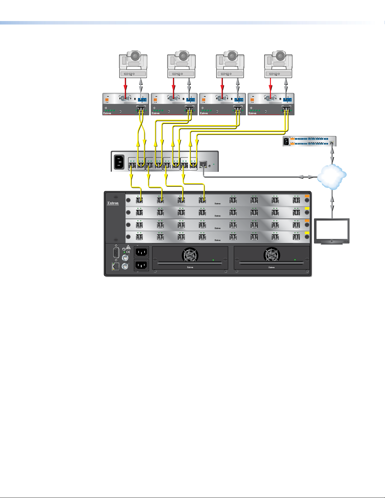
About the Inserter
The FOX RS 104 is a four fiber optic port RS-232 Inserter that provides local insertion points
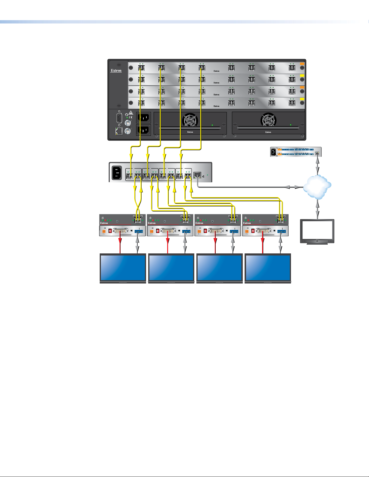
on the input (see figure 1, on the next page) or output (see figure 2 on page 3) of a fiber
optic matrix switcher for long-haul RS-232 control. Each port provides a bidirectional fiber
optic connection to a FOX matrix switcher for the insertion and extraction of control data,
while maintaining a continuous pass-through link for video and audio. The inserter can be
installed, along with its control system, in the same equipment rack as the matrix switcher,
rather than at the remote fiber optic transmitter or receiver location.
The LAN port on the inserter allows direct insertion of bidirectional serial control to individual
fiber optic inputs or outputs, simplifying control and eliminating the need for additional
transmitters, receivers, and extra cabling.
The inserter is compatible with all FOX 500, FOXBOX, and PowerCage FOX products with
RS-232 control now and in the future.
The inserter is housed in a 6-inch deep, half rack width, 1U high metal enclosure. With
optional rack shelves, the inserter can be installed in a standard 19-inch equipment rack.
The inserter has a 100 VAC to 240 VAC, 50-60 Hz, 20-watt power supply that provides
worldwide power compatibility.
The inserter can be remotely controlled using either built-in HTML pages or the Simple
Instruction Set (SIS™), available via the rear panel LAN port. The SIS is a set of basic ASCII
code commands that provide simple control through a control system or PC without the
need to enter long strings of code.
FOX RS 104 RS-232 Inserter • Introduction 1
Page 8
ANAHEIM, CA
RESET
REMOTE
RS-232/RS-422
LAN
BI-LEVEL
TRI-LEVEL
ACT LINK
100-240V 50/60Hz 1.2A MAX.
100-240V 50/60Hz 1.2A MAX.
REDUNDANT
PRIMARY
DISCONNECT BOTH POWER
CORDS BEFORE SERVICING
SWITCH
REFERENCE
PRIMARY POWER SUPPLY
REDUNDANT POWER SUPPLY
1 - 8
9 - 16
17 - 24
25 - 32
OUT
IN
A
OUT
IN
D
OUT
IN
C
OUT
IN
B
OUT
IN
E
OUT
IN
H
OUT
IN
G
OUT
IN
F
OUT
IN
A
OUT
IN
D
OUT
IN
C
OUT
IN
B
OUT
IN
E
OUT
IN
H
OUT
IN
G
OUT
IN
F
OUT
IN
A
OUT
IN
D
OUT
IN
C
OUT
IN
B
OUT
IN
E
OUT
IN
H
OUT
IN
G
OUT
IN
F
OUT
IN
A
OUT
IN
D
OUT
IN
C
OUT
IN
B
OUT
IN
E
OUT
IN
H
OUT
IN
G
OUT
IN
F
MM R
SM R
MM R
SM R
100-240V ~ 50/60 Hz
-- A MAX
A B
1
Tx Rx
Tx Rx
A B
2
Tx Rx
Tx Rx
A B
3
Tx Rx
Tx Rx
A B
4
Tx Rx
Tx Rx
LAN
RESET
FLEX I/O
SWITCHED 12VDC
40W MAX TOTAL
LAN
1 2 3 4 G
COM1
TxRx G G G G
RTS CTS
IR/SERIAL
1
S G S G
2
RELAY
3
S G S G
+- + -
+- +-
4 1 21 2 3 4
3 4
5
S G S G
6 7
S G S G
8 5 6 7 8
COM2
TxRx
COM3
TxRx
COM7
TxRx
COM4
TxRx G G G G
RTS CTS
COM5
TxRx
COM6
TxRx
COM8
TxRx
eBUS
+V
PWR OUT = 12W
DG -S+S
5A MAX
100-240V 50-60Hz
AUDIO
RGB/YUV INPUT
FOXBOX Tx VGA/YUV
RS-232
OVER FIBER
ALARM
Tx Rx 1 2
12V
1.0A MAX
POWER
FOXBOX Tx VGA/YUV
RGB/
YUV
OVER
TEMP
AUDIO
CONFIG
OPTICAL
Rx
Tx
LINK
LINK
AUDIO
RGB/YUV INPUT
FOXBOX Tx VGA/YUV
RS-232
OVER FIBER
ALARM
Tx Rx 1 2
12V
1.0A MAX
POWER
FOXBOX Tx VGA/YUV
RGB/
YUV
OVER
TEMP
AUDIO
CONFIG
OPTICAL
Rx
Tx
LINK
LINK
AUDIO
RGB/YUV INPUT
FOXBOX Tx VGA/YUV
RS-232
OVER FIBER
ALARM
Tx Rx 1 2
12V
1.0A MAX
POWER
FOXBOX Tx VGA/YUV
RGB/
YUV
OVER
TEMP
AUDIO
CONFIG
OPTICAL
Rx
Tx
LINK
LINK
AUDIO
RGB/YUV INPUT
FOXBOX Tx VGA/YUV
RS-232
OVER FIBER
ALARM
Tx Rx 1 2
12V
1.0A MAX
POWER
FOXBOX Tx VGA/YUV
RGB/
YUV
OVER
TEMP
AUDIO
CONFIG
OPTICAL
Rx
Tx
LINK
LINK
PTZ Camera 4PTZ Camera 3PTZ Camera 1 PTZ Camera 2
Ethernet
RS-232
Fiber
FiberFiber
Fiber
RS-232 RS-232 RGB RS-232 RGB RGB RGB
Ethernet
Ethernet
Extron
FOX Matrix 3200
Modular Fiber Optic Matrix Switcher
Extron
FOX RS 104
Fiber Optic
RS-232 Inserter
TCP/ IP
Network
Extron
IPCP 505
IP Link Control
Processor
Extron
TLP 1000TV
10" Tabletop
TouchLink
Touchpanel
Extron
FOXBOX Tx VGA/YUV
Fiber Optic Transmitter
Figure 1. Typical Inserter Application on the Matrix Switcher Input
FOX RS 104 RS-232 Inserter • Introduction 2
Page 9
Extron
FOX Matrix 3200
Modular Fiber Optic Matrix Switcher
OUT
IN
1 - 8
RESET
BI-LEVEL
TRI-LEVEL
SWITCH
REFERENCE
Tx Rx
9 - 16
17 - 24
25 - 32
100-240V 50/60Hz 1.2A MAX.
DISCONNECT BOTH POWER
CORDS BEFORE SERVICING
100-240V 50/60Hz 1.2A MAX.
1
Tx Rx
A B
Tx
LINK
OPTICAL
RS-232
AUDIO
OVER FIBER
Tx Rx 1 2
A
OUT
IN
A
OUT
IN
A
OUT
IN
A
2
Tx Rx
A B
Rx
LINK
POWER
12V
1.0A MAX
ALARM
ANAHEIM, CA
REMOTE
RS-232/RS-422
LAN
ACT LINK
100-240V ~ 50/60 Hz
-- A MAX
Extron
FOXBOX Rx
DVI Plus
Fiber Optic
Receiver
DVI
OVER
TEMP
AUDIO
CONFIG
FOXBOX Rx DVI Plus
POWER
MODE
12V
DVI-D OUTPUT
1.0A MAX
1ON2
FOXBOX Rx DVI Plus
OUT
IN
C
IN
C
IN
C
IN
C
4
Tx Rx
IN
D
OUT
IN
D
OUT
IN
D
OUT
IN
D
LAN
RESET
OUT
IN
E
OUT
IN
E
OUT
IN
E
OUT
IN
E
Extron
FOX RS 104
Fiber Optic
RS-232 Inserter
OUT
IN
F
OUT
IN
F
OUT
IN
F
OUT
IN
F
REDUNDANT POWER SUPPLY
OUT
IN
G
OUT
IN
G
OUT
IN
G
OUT
IN
G
100-240V 50-60Hz
COM1
TxRx G G G G
+- + -
SWITCHED 12VDC
40W MAX TOTAL
COM4
3 4
TxRx G G G G
+- +-
5A MAX
Extron
IPCP 505
IP Link Control
Processor
B
B
B
B
Tx Rx
IN
IN
IN
IN
3
A B
Tx Rx
OUT
OUT
OUT
OUT
PRIMARY POWER SUPPLY
Tx Rx
A B
OUT
OUT
OUT
OUT
REDUNDANT
PRIMARY
Tx Rx
OUT
H
OUT
H
OUT
H
OUT
H
COM2
COM3
COM7
TxRx
TxRx
TxRx
COM5
COM6
COM8
TxRx
TxRx
TxRx
Ethernet
MM R
IN
SM R
IN
MM R
IN
IN
SM R
2
3
4 1 21 2 3 4
1
eBUS
S G S G
S G S G
RTS CTS
+V
DG -S+S
LAN
PWR OUT = 12W
RELAY
IR/SERIAL
5
6 7
8 5 6 7 8
FLEX I/O
S G S G
S G S G
RTS CTS
1 2 3 4 G
Ethernet
TCP/ IP
Network
Ethernet
Rx
FOXBOX Rx DVI Plus
FOXBOX Rx DVI Plus
Tx
LINK
OPTICAL
RS-232
AUDIO
OVER FIBER
Tx Rx 1 2
DVI
OVER
TEMP
AUDIO
LINK
ALARM
CONFIG
FOXBOX Rx DVI Plus
POWER
MODE
12V
DVI-D OUTPUT
1.0A MAX
1ON2
FOXBOX Rx DVI Plus
DVI
OVER
TEMP
AUDIO
CONFIG
MODE
DVI-D OUTPUT
1ON2
Rx
Tx
LINK
OPTICAL
RS-232
AUDIO
OVER FIBER
Tx Rx 1 2
DVI
OVER
TEMP
AUDIO
LINK
ALARM
CONFIG
FOXBOX Rx DVI Plus
POWER
MODE
12V
DVI-D OUTPUT
1.0A MAX
1ON2
FOXBOX Rx DVI Plus
Rx
Tx
LINK
LINK
OPTICAL
RS-232
AUDIO
ALARM
OVER FIBER
Tx Rx 1 2
RS-232RS-232RS-232RS-232DVI DVI DVI DVI
Extron
TLP 1000TV
10" Tabletop
TouchLink
Touchpanel
Flat Panel Display 1 Flat Panel Display 2 Flat Panel Display 3 Flat Panel Display 4
Figure 2. Typical Inserter Application on the Matrix Switcher Output
Fiber Cable Transmission Modes
Two versions of the inserter are documented in this guide. They are categorized by the
type of fiber optic cable, multimode or singlemode, which defines the effective range of
transmission:
• Multimode — Long distance, up to 300 m (985 feet)
• Singlemode — Very long distance, up to 30 km (18.75 miles)
FOX RS 104 RS-232 Inserter • Introduction 3
Page 10

Features
RS-232 insertion to or extraction from one or more of the fiber optic outputs (or
both insertion and extraction) from the Ethernet port— Allows direct insertion of
bidirectional serial control data into an optical signal.
Standard fiber optic signal architecture — Compatible optical signals are digital signals
from 270 Mbps through 4.25 Gbps that are sent and received via fiber optic small form
factor pluggable (SFP) modules with LC-type connectors. The inserter is compatible with
FOX matrix switchers and DAs and FOX, FOXBOX, and PowerCage FOX transmitters and
receivers.
Buffered fiber optic outputs — Original power level is maintained on each output to
maximize distance capabilities and ensure full availability of optical loss budget.
Output reclocking — Reshapes and restores timing of the digital signal.
Ethernet monitoring and control — Enables Web-based remote management,
monitoring, and control.
Ethernet connectivity for integration with a control system — Eliminates the need for
separate control system wiring to remote devices.
Real-time status LED indicators for troubleshooting and monitoring — Rear panel
LEDs verify link status and power.
Rack-mountable 1U, half rack width metal enclosure
Internal universal power supply — The 100-240 VAC, 50/60 Hz, international power
supply provides worldwide power compatibility.
FOX RS 104 RS-232 Inserter • Introduction 4
Page 11
Installation and
Operation
This section details the installation and operation of the FOX RS 104 Inserter, including:
• Rear Panel Connections
• Operation
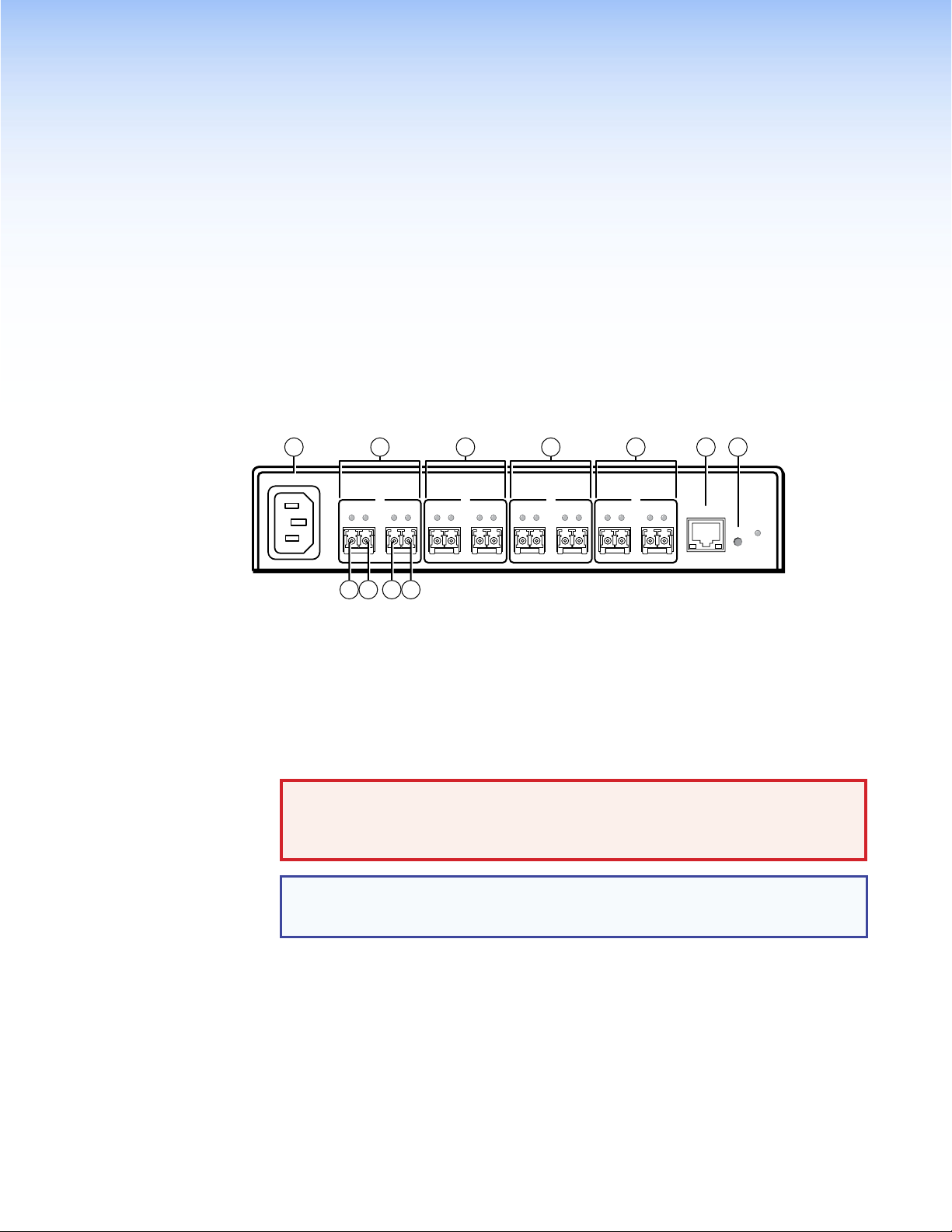
Rear Panel Connections
4
1 1 1 1
2 3
100-240V ~ 50/60 Hz
0.3 A MAX
1
Tx Rx
Tx Rx
ABABABAB
1a 1b
1c 1d
Tx Rx
2
Tx Rx
Tx Rx
3
Tx Rx
Tx Rx
4
Tx Rx
FOX RS 104
LAN
RESET
Figure 3. FOX RS 104 Inserter Connectors
a Fiber optic connectors and LEDs — Each port, 1 through 4, has two SFP optical
transceiver modules with LC connectors, labeled “A” and “B”. How to connect these
transceivers is determined by where the inserter is installed, typically on the input of
a matrix switcher or on the output. Transceiver B is connected to an internal UART
that inserts serial communications into the fiber optic signal or extracts the serial
communications, depending on the application. See “Fiber connection examples” on
page 7 for detailed connection diagrams in typical applications.
WARNING: Risk of eye injury. The fiber optic FOX inserter outputs continuous
invisible light that may be harmful to the eyes; use with caution. For additional
safety, plug the attached dust caps into the transceivers when the fiber cable is
unplugged.
NOTE: Ensure that you use the proper fiber cable for your inserter. Typically,
singlemode fiber has a yellow jacket and multimode cable has an orange or aqua
jacket.
Ä Tx A — For one-way communications from the inserter to a downstream device,
typically a matrix switcher, connect a fiber optic cable to the Tx A LC connector.
Connect the free end of this fiber optic cable to the In or Rx connector on the
downstream device.
Å Rx A — For one-way transmission from an upstream device, typically a matrix
switcher, connect a fiber optic cable to the Rx A LC connector.
Connect the free end of this fiber optic cable to the Out or Tx connector on the
upstream device.
FOX RS 104 RS-232 Inserter • Installation and Operation 5
Page 12

û Tx B — For one-way communications from the inserter to a downstream device,
which typically can be either a receiver or a transmitter, depending on the
application, connect a fiber optic cable to the Tx B LC connector.
Connect the free end of this fiber optic cable to the Rx connector on the
downstream device.
ü Rx B — For one-way transmission from an upstream device, which typically can be
either a transmitter or a receiver, depending on the application, connect a fiber optic
cable to the Rx B LC connector.
Connect the free end of this fiber optic cable to the Tx connector on the upstream
device.
Tx Link and Rx Link LEDs — When lit, the link is active (light is received).
b LAN port — For IP control of the inserter with SIS commands or downloaded HTML
pages from the inserter and to insert serial data into and extract it from the fiber stream,
connect the unit to a PC or to an Ethernet LAN via this RJ-45 connector. You can use a
PC for control and serial data insertion and extraction from anywhere in the world. See
“LAN port cabling” on page 8 for connection information.
Link LED indicator — The green (link) LED indicates that the inserter is properly
connected to an Ethernet LAN. This LED should light steadily.
Act LED indicator — The yellow (activity) LED indicates transmission of data packets
on the RJ-45 connector. This LED should flicker as the inserter communicates.
c Reset button — The recessed Reset button initiates four levels of inserter
reset. For four different reset levels, press and hold the button while the inserter
is running or while you power up the inserter.
See “Rear Panel Reset Operations” on page 9 for details.
• Events (mode 3) reset — Toggles events monitoring on and off.
• IP settings (mode 4) reset — Resets the IP functions of the inserter.
RESET
NOTE: The IP settings reset does not replace any user-installed firmware.
• Absolute (mode 5) reset — Restore the inserter to the default factory conditions.
• Hard reset — Restore the inserter to the default factory conditions and return the
inserter to the default firmware that shipped with the unit.
NOTES:
• Factory loaded firmware is active until it is replaced or the power is cycled.
• Hard reset does not clear the current configuration.
d AC power connector — Plug a standard IEC power cord into this connector to
connect the FOX RS 104 to a 100 VAC to 240 VAC, 50-60 Hz power source.
FOX RS 104 RS-232 Inserter • Installation and Operation 6
Page 13

Making Connections
FOX Matrix Switcher
Fiber connection examples
The fiber optic cable connections is determined by the installation relative to a matrix switcher.
When the inserter is installed on matrix switcher input (see figure 4, below):
• SFP transceiver B (a) receives the source optical signal, consisting of video and audio.
• The inserter throughputs the RS-232 stream via the LAN port (b) and inserts it into or
extracts it from the optical signal stream via the UART and SFP transceiver B (c).
• The inserter outputs the video and audio optical signal on SFP A (d). It outputs the
inserted serial stream to the transmitter (which routes it to the controlling device) on
SFP A (e).
Tx
Rx
FOX
Transmitter
Video & Audio
Video & Audio
OUT
IN
Inserted RS-232
5
Tx Rx
4
AB
1
Tx Rx
UART
RS-232
3
1
LAN
UART Port Telnet Port
1
2
3
4
Ethernet
2
LAN
2001
2002
2003
2004
Control
PC or
Control System
Video & Audio
FOX Matrix Switcher
Figure 4. Typical Wiring Diagram for an Inserter on a Matrix Switcher Input
When the inserter is installed on matrix switcher output (see figure 5, below):
• SFP transceiver A (a) receives the source optical signal.
• The inserter throughputs the RS-232 command stream via the LAN port (b) and inserts it
into or extracts it from the optical signal stream via the UART and SFP transceiver B (c).
• The inserter outputs the optical signal, with the inserted serial stream, to the receiver on
SFP B (d).
OUT
IN
Video, Audio, &
Inserted RS-232
Tx
Rx
FOX RS 104
Fiber Optic RS-232 Inserter
UART
RS-232
4
Tx Rx
3
LAN
1
Tx Rx
1
AB
Fiber optic signal
Ethernet signal
Internal signal
UART Port Telnet Port
1
2
3
4
2
Ethernet
LAN
2001
2002
2003
2004
Control
PC or
Control System
FOX Receiver
Figure 5. Typical Wiring Diagram for an Inserter on a Matrix Switcher Output
FOX RS 104
Fiber Optic RS-232 Inserter
Optical return signal
Fiber optic signal
Ethernet signal
Internal signal
FOX RS 104 RS-232 Inserter • Installation and Operation 7
Page 14

LAN port cabling
Crossover Cable Straight-through Cable
It is vital that your Ethernet cables be the correct cable type and that they be properly
terminated with the correct pinout. Ethernet links use Category (CAT) 5e or CAT 6,
unshielded twisted pair (UTP) or shielded twisted pair (STP) cables, terminated with RJ-45
connectors. Ethernet cables are limited to a length of 328 feet (100 m).
NOTES: • Donotusestandardtelephonecables.Telephonecablesdonotsupport
Ethernet or Fast Ethernet.
• Do not stretch or bend cables. Transmission errors can occur.
The cable used depends on your network speed. The inserter supports both
10 Mbps (10Base-T — Ethernet) and 100 Mbps (100Base-T — Fast Ethernet), half-duplex
and full-duplex Ethernet connections.
• 10Base-T Ethernet requires CAT 3 UTP or STP cable at minimum.
• 100Base-T Fast Ethernet requires CAT 5e UTP or STP cable at minimum.
The Ethernet cable can be terminated as a straight-through cable or a crossover cable and
must be properly terminated for your application (see figure 6).
• Crossover cable — Direct connection between the computer and the inserter
• Patch (straight) cable — Connection of the FOX inserter to an Ethernet LAN
Pins:
12345678
Pin
Insert Twisted
Pair Wires
Connector
RJ-45
A cable that is wired as T568A at one end
and T568B at the other (Tx and Rx pairs
reversed) is a "crossover" cable.
End 1 End 2 End 1 End 2
Wire color
1
White-green
2
Green
3
White-orange
4
Blue
5
White-blue
6
Orange
7
White-brown
8
Brown
T568A T568B
Wire color
White-orange
Orange
White-green
Blue
White-blue
Green
White-brown
Brown
Pin
Wire color
1
White-orange
2
3
White-green
4
Blue
5
White-blue
6
7
White-brown
8
Brown
A cable that is wired the same at both ends is
called a "straight-through" cable, because
no pin/pair assignments are swapped.
Wire color
White-orange
OrangeOrange
White-green
Blue
White-blue
GreenGreen
White-brown
Brown
T568BT568B
Operation
Front Panel Features
Figure 6. RJ-45 Connector and Pinout Tables
INPUT DATA RATE
2.125G
4.25G
FOX RS 104
FIBER RS-232 INSERTER
1 2
Figure 7. FOX RS 104 Front Panel Features
a Power LED — This LED lights green when power is applied.
b Input Data Rate switch — This switch selects between the 2.125 Gbits (2G) and
4.25 Gbits (4G) input data rate. After switching data rates, cycle power to the inserter to
properly lock onto the selected input data rate.
FOX RS 104 RS-232 Inserter • Installation and Operation 8
Page 15

Rear Panel Reset Operations
Release, then immediately
press and release again.
RESET
RESET
RESET
Release, then immediately
press and release again.
6 seconds
9 seconds
Press and hold
the Reset button.
3 seconds
Reset LED flashes once.
Release, then immediately
press and release again.
Reset LED flashes twice.
Press and hold
the Reset button.
Press and hold
the Reset button.
Reset LED flashes
three times.
IP Settings
Reset
(Mode 4)
Absolute
Reset
(Mode 5)
Events
Reset
(Mode 3)
The rear panel Reset button initiates four levels of resets (numbered 1, 3, 4, and 5 for the
sake of comparison with an Extron IPL product). The Reset button is recessed, so use a
pointed stylus, ballpoint pen, or small screwdriver to access it.
See the table on the next page for a summary of the modes.
ATTENTION: Review the reset modes carefully. Using the wrong reset mode may result
in unintended loss of flash memory programming, port reassignment, or a controller
reboot.
Performing Soft System Resets (Resets 3, 4, and 5)
Perform a soft reset of the inserter as follows (see figure 8):
1. Use a small screwdriver to press and hold the rear panel Reset button until the
rear panel Reset LED blinks once (events reset), twice (system reset), or three times
(absolute reset).
Figure 8. Resets
2. Release the Reset button and then immediately press and release the Reset button
again. Nothing happens if the second momentary press does not occur within 1
second.
FOX RS 104 RS-232 Inserter • Installation and Operation 9
Page 16

NOTE: The reset modes listed below close all open IP and Telnet connections and close
all sockets. Also, the following modes are separate functions, not a continuation from
mode 1 to mode 5.
Reset Mode Comparison and Summary
Mode Activation Result Purpose and notes
1 Hold down the recessed Reset button while
applying power to the inserter.
NOTE: After a mode 1 reset is
performed, update the inserter
firmware to the latest version. Do
not operate the inserter firmware
version that results from the mode
1 reset. If you want to use the
factory default firmware, you must
upload that version again. See
“Firmware Upgrade page” on
page 23 for details on uploading
firmware.
The inserter reverts to the factory default firmware.
Event scripting does not start if the inserter is powered on in
this mode. All user files and settings, such as IP settings, are
maintained.
NOTE: If you do not want to update firmware, or you
performed a mode 1 reset by mistake, cycle power
to the inserter to return to the firmware version that
was running before the mode 1 reset. Use the 0Q SIS
command to confirm that the factory default firmware
is no longer running (look for the asterisk [*] following
the version number.
Use mode 1 to return
the inserter to the
factory default firmware
version if incompatibility
issues arise with
user-loaded firmware.
3 Hold the Reset button for approximately
3 seconds, until the Reset LED blinks once,
then momentarily press Reset for less than
Mode 3 turns events on or off. During resetting, the
Reset LED flashes 2 times if events are starting, 3 times if
events are stopping.
Mode 3 is useful for
troubleshooting.
1 second within 1 second.
4 Hold the Reset button for approximately
6 seconds, until the Reset LED blinks
twice (once at 3 seconds and again at 6
seconds). Then momentarily press Reset
for less than 1 second within 1 second.
Mode 4:
• Enables ARP capability.
• Sets the IP address to the factory default.
• Sets the subnet address to the factory default.
• Sets the gateway address to the factory default.
• Sets port mapping to the factory default.
• Turns DHCP off.
• Turns events off.
The Reset LED flashes four times in quick succession during
Mode 4 enables you
to set IP address
information using ARP
and the MAC address.
the reset.
5 Hold the Reset button for approximately
9 seconds, until the Reset LED blinks
three times (once at 3 seconds, again at
6 seconds, and then again at 9 seconds).
Then momentarily press Reset for less than
1 second within 1 second.
Mode 5 performs a complete reset to factory defaults
(with the exception of the firmware):
• Does everything mode 4 does.
• Resets all IP options.
• Removes all files from the inserter.
The reset LED flashes four times in quick succession during the
Mode 5 is useful if
you want to start over
with configuration and
uploading or to replace
events.
Same as the
E
ZQQQ} SIS
command.
reset.
FOX RS 104 RS-232 Inserter • Installation and Operation 10
Page 17

System Operation
After the transmitter, all receivers, the matrix switcher, the inserter, and their connected
devices are powered up, the system is fully operational. If any problems are encountered,
verify that the cables are routed and connected properly, and that all display devices have
identical resolutions and refresh rates. If your problems persist, call the Extron S3 Sales &
Technical Support Hotline. See the contact numbers on the last page of this guide for the
Extron office nearest you.
To insert RS-232 commands into the fiber optic signal stream and to extract RS-232
responses from the stream, you need to connect a computer or other Ethernet-capable
device to the rear panel LAN port. The LAN connection is also necessary to configure the
inserter using either SIS commands or the built-in HTML pages.
FOX RS 104 RS-232 Inserter • Installation and Operation 11
Page 18

Remote Control
This section describes the remote control operation of the FOX RS 104, including:
• Simple Instruction Set Control
• HTML Operation
You can use Simple Instruction Set (SIS) commands or built-in HTML pages for operation
and configuration of the inserter. You can remotely operate the inserter from a PC connected
to the LAN port (item b on page 6).
Simple Instruction Set Control
Host-to-Unit Instructions
SIS commands consist of one or more characters per field. No special characters are
required to begin or end a command character sequence. When a command is valid, the
unit executes the command and sends a response to the host device. All responses from
the unit to the host end with a carriage return and a line feed (CR/LF = ]), which signals the
end of the response character string. A string is one or more characters.
Unit-initiated Messages
The inserter issues the following copyright message when it detects an IP connection. xx is
MM (multimode) or SM (singlemode), Vn.nn is the firmware version number; 60-1273-zz is the
part number of the connected unit.
(c) Copyright 20nn, Extron Electronics FOX RS 104 xx, Vn.nn,
60-1273-zz Day, Date, Time
Error Responses
When the unit receives a valid SIS command, it executes the command and sends a
response to the host device. If the unit is unable to execute the command because the
command is invalid or it contains invalid parameters, the unit returns an error response to
the host. The error response codes are:
E10 – Invalid command
E13 – Invalid parameter
E14 – Invalid command for this configuration
]]
FOX RS 104 RS-232 Inserter • Remote Control 12
Page 19

Using the Command and Response Tables
ASCII to Hex Conversion Table
•
Space
The command and response table begins on page 15. Either uppercase or lowercase
letters are acceptable in the command field except where indicated for the audio level (gain
and attenuation) commands. Symbols, defined below, are used throughout the table to
represent variables in the command and response fields. Command and response examples
are shown throughout the table. The ASCII to Hex conversion table below is for use with the
command and response table.
Symbol Definitions
] = CR/LF (carriage return/line feed)
} = Carriage return (no line feed)
| = Pipe (can be used interchangeably with the } character)
= Space (hard) character
•
E = Escape key (hex 1B)
W = Can be used interchangeably with the E character
X! = Port number 1 through 4
X@ = Enable and disable status 0 = disable 1 = enable
X# = Firmware version v.vv
X$ = Verbose firmware version-description-upload date/time. See the Query controller firmware version (verbose) command on page 15.
X% = Inserter name (Up to 24 alphanumeric characters)
NOTE: The HTML language reserves certain characters for specific functions (see “Special Characters” on page 28).
X^ = Default name FOX-RS-104-nn- plus the last 3 pairs of MAC address. nn is either SM (singlemode) or
MM (multimode).
X& =Timeanddate(forset) Intheformat:MM/DD/YY•HH:MM:SSwhere:
MM = month: 01 (January) through 12 (December)
DD = day: 01 through 31
YY = year: 00 through 99
HH = hour: 00 through 23
MM = minutes: 00 through 59
SS = seconds: 00 through 59
X* =Timeanddate(forread) Intheformat:Day,•DD•Mmm•YYYY•HH:MM:SSwhere:
Day = weekday: Mon through Sun
DD = date: 01 through 31
Mmm = month: Jan through Dec
YYYY = year: 2000 through 2099
HH = hour: 00 through 24
MM = minutes: 00 through 59
X( = GMT offset –12.0 through +14.0. Hours and minutes removed from GMT
X1) = Daylight Saving Time 0 = Daylight Saving Time off/ignore 2 = Daylight Saving Time on (Europe)
SS = seconds: 00 through 59
1 = Daylight Saving Time on (North America) 3 = Daylight Saving Time on (Brazil)
X1! = IP address ###.###.###.###
X1@ = Hardware (MAC) address ##-##-##-##-##-##
FOX RS 104 RS-232 Inserter • Remote Control 13
Page 20

X1# = Number of open connections 0 – 200
X1$ = Password 12 alphanumeric characters
NOTE: The HTML language reserves certain characters for specific functions (see “Special Characters” on page 28).
X1% = DHCP 0 =off, 1 = on
X1^ = Baud rate 9600, 19200, 38400, 115200
X1& = Parity odd, even, none, mark, space (Only the first letter required.)
X1* = Data bits 7, 8
X1( = Stop bits 1, 2
X2) = Port type (always 0 = RS-232)
X2! = Verbose mode 0 = clear/none (default for Telnet connection) 2 = tagged responses for queries
1 = verbose mode (default for RS-232) 3 = verbose mode and tagged for queries
NOTE: If tagged responses is enabled, all read commands return the constant string and the value as the set command does
(for example, the read matrix name command, ECN},returnsIpn•
X%]
).
X2@ = Port timeout interval (in 10-sec. increments) 1 (= 10 seconds) – 65000 (default is 30 = 300 seconds = 5 minutes)
X2# = Direct access port map 0 (= disabled) or 1024 and up (default is 2001)
FOX RS 104 RS-232 Inserter • Remote Control 14
Page 21

Command and Response Table for Inserter SIS Commands
Command ASCII Command
(host to unit)
Response
(unit to host)
Additional description
Enable and disable serial insertion ports
Enable one port
Disable one port
Enable all ports
Disable all ports
View port status
EX!
EX!
E
0*1LRPT
E
0*0LRPT
EX!
}
*1LRPT
}
*0LRPT
}
}
} X@]
LRPT
LrptX!*1
LrptX!*0
Lrpt0*1
Lrpt0*0
]
]
]
]
Enable serial insertion port X!
(allow data to be inserted onto fiber optic port
Disable serial insertion port X!.
X!
).
Information requests
Request name
Request part number
NOTE: There are up to three separate sets of Extron firmware on which the inserter can report: the controller firmware, which is the
overall control firmware; the Ethernet protocol firmware, which handles the Ethernet interface; and the latest optional Extron firmware
update, which is available at www.extron.com.
Query firmware version
Example:
Query controller firmware
version (verbose)
Response description:
Example:
Description
3.00-0.99(1.81-IPL Series -Wed, 16 Jan 2003 00:00:00 GMT)-1.00*(1.81-IPL Series -Wed, 24 Oct 2002 08:02:33 GMT)
Ethernet
protocol firmware
I
N
Q
Q
0Q
Ethernet protocol firmware version-controller firmware version-updated firmware version
0q
IP Link firmware version
FOX RS 104 nn
60-1273-nn
X#]
]
1.23
X#-X$-X$]
]
nn is either SM (singlemode) or MM (multimode).
]
nn is either 02 (singlemode) or 01 (multimode).
The factory-installed firmware version is 1.23 (sample
value only).
Provide a detailed status of the Ethernet protocol firmware,
the controller firmware, and any firmware upgrade. The
firmware that is running is marked by an asterisk (*). A
caret (^) indicates that the firmware has a bad checksum or
an invalid load. ?.?? indicates that firmware is not loaded.
]
* indicates the version running Upload date and time
Updated firmware version
Resets
System reset
Reset flash memory
Absolute reset
Absolute reset, but retain IP
IP setup
Set inserter name
Read inserter name (location)
Reset inserter name to factory
default
Set time and date
Read time and date
Set GMT offset
Example:
Read GMT offset
Set Daylight Savings Time
Read Daylight Savings Time
E
E
E
EZY}
EX%CN}
ECN} X%]
E
EX&CT}
ECT} X*]
EX(CZ}
E
ECZ} X(]
EX1)CX}
ECX} X1)]
ZXXX
ZFFF
ZQQQ
}
•CN
8.3CZ
}
}
}
}
]
Zpx
]
Zpf
]
Zpq
]
Zpy
X%]
Ipn•
X^]
Ipn•
X&]
Ipt
X(]
Ipz
Ipz+08:30
X1)]
Ipx
]
Reset all settings to factory defaults.
Reset all settings, including IP address and subnet mask.
Reset all settings except IP settings to factory defaults.
See X^ definition below.
In the command, the divider between hours and minutes
can be either a colon or a period. In the response, the
divider is a colon.
8.3 = 8:30.
NOTE: X! = Port number 1 through 4
X@
= Enable and disable status 0 = disable 1 = enable
X#
= Firmware version v.vv
X$
= Verbose firmware version-description-upload date/time. See above.
X%
= Inserter name (Up to 240 alphanumeric characters)
X^
= Default name FOX-RS-104-nn- plus the last 3 pairs of MAC address. nn is SM or MM.
X&
= Time and date (for set) In the format: MM/DD/YY•HH:MM:SS
X*
=Timeanddate(forread) Intheformat:Day,•DD•Mmm•YYYY•HH:MM:SS
X(
= GMT offset –12.0 through +14.0. Hours and minutes removed from GMT
X1)
= Daylight Saving Time 0 = Off/ignore 1 = North America 2 = Europe 3 = Brazil
FOX RS 104 RS-232 Inserter • Remote Control 15
Page 22

Command ASCII Command
(host to unit)
Information requests (Continued)
Set IP address
Read IP address
Read hardware address
Read # of open connections
Set subnet mask
Read subnet mask
Set gateway IP address
Read gateway IP address
Set administrator password
Read administrator password
Reset (clear) administrator
password
Set user password
Read user password
Reset (clear) user password
Set DHCP on or off
Read DHCP on/off status
Set serial port parameters
Read serial port parameters
Set serial port mode
Read serial port mode
Set verbose mode
Read verbose mode
Configure current port timeout
Read current port timeout
Configure global IP port timeout
Read global IP port timeout
Set direct access port map
Reset direct access port map
View direct access port map
EX1!CI}
ECI} X1!]
ECH} X1@]
ECC} X1#]
EX1!CS}
ECS} X1!]
EX1!CG}
ECG} X1!]
EX1$CA}
ECA} X1$]
E
}
•CA
EX1$CU}
ECU} X1$]
E
}
•CU
EX1%DH}
EDH} X1%]
EX!*X1^,X1&,X1*,X1(CP}
EX!CP} X1^,X1&,X1*,X1(]
EX!*X2)CY}
EX!CY} X2)]
EX2!CV}
ECV} X2!]
E0*X2@TC}
E
} X2@]
0TC
E1*X2@TC}
E
} X2@]
1TC
EX2#MD}
E
2001MD
}
EMD} X2#]
Response
(unit to host)
X1!]
Ipi
X1!]
Ips
X1!]
Ipg
X1$]
Ipa•
]
Ipa•
X1$]
Ipu•
]
Ipu•
X1%]
Idh
CpnX!•Ccp
CpnX!•Cty
Vrb
Pti0*
Pti1*
Pmd
Pmd02001
X1^,X1&,X1*,X1(]
X2)] X2)
X2!]
X2@]
X2@]
X2#]
]
Additional description
Reads MAC address.
is always 0 (RS-232)
Resets the direct access port number to 2001.
NOTE: X! = Port number 1 through 4
X1!
= IP address ###.###.###.###
X1@
= Hardware (MAC) address ##-##-##-##-##-##
X1#
= Number of open connections 0 – 200
X1$
= Password 12 alphanumeric characters
X1%
= DHCP 0 =off, 1 = on
X1^
= Baud rate 9600, 19200, 38400, 115200
X1&
= Parity odd, even, none, mark, space (Only the first letter required.)
X1*
= Data bits 7 or 8
X1(
= Stop bits 1 or 2
X2)
= Port type (always 0 = RS-232)
X2!
= Verbose mode 0 = clear/none (default for Telnet connection) 2 = tagged responses for queries
1 = verbose mode (default for RS-232) 3 = verbose mode and tagged for queries
X2@
= Port timeout interval 1 (= 10 seconds) – 65000 (default is 30 = 300 seconds = 5 minutes)
X2#
= Direct access port map 0 (= disabled) or 1024 and up (default is 2001)
FOX RS 104 RS-232 Inserter • Remote Control 16
Page 23

HTML Operation
Opening the Embedded Web Pages
The inserter can be controlled and operated through its LAN port, connected via a LAN
or WAN, using a web browser such as the Microsoft Internet Explorer. The display in the
browser of the status or operation of the inserter has the appearance of web pages. This
chapter describes the factory-installed HTML pages, which are always available and cannot
be erased or overwritten.
NOTE: If your Ethernet connection to the inserter is unstable, try turning off the proxy
server in your Web browser. In Microsoft Internet Explorer, click
Options > Connections > LAN Settings
and then click OK.
Access the inserter using HTML pages as follows:
1. Start the web browser program.
2. Click in the Address field of the browser.
3. Enter the inserter address in the Address field of the browser.
NOTE: If the local system administrators have not changed the value, the
factory-specified default, 192.168.254.254, is the correct value for this field.
4. If you want the browser to display a page other than the default page (such as a
custom page that you have uploaded), enter a slash (/) and the file name to open.
, uncheck the
Use a proxy server...
Tools > Internet
box,
NOTES:
• The
• The HTML language reserves certain characters for specific functions (see
5. Press the keyboard <Enter> key. The inserter checks to see if it is password protected.
If the inserter is not password protected, it checks and downloads the HTML pages
(proceed to step 6).
If the inserter is password protected, the inserter downloads the Windows Security
page (see figure 9).
Address
format: <xxx.xxx.xxx.xxx>/<optional_file_name>.html.
“Special Characters” on page 28).
field of the browser should display the address in the following
Figure 9. Windows Security Page
FOX RS 104 RS-232 Inserter • Remote Control 17
Page 24

Status Tab
NOTE: A User name entry is not required.
6. Click in the Password field and type in the appropriate administrator or user password.
Click the OK button.
The inserter checks several possibilities, in the following order, and then responds
accordingly:
• Does the address include a specific file name, such as
10.13.156.10/<file_name>.html?
If so, the inserter downloads that HTML page.
• Is there a file in the inserter memory that is named “index.html”?
If so, the inserter downloads “index.html” as the default startup page.
• If neither of the above conditions is true, the inserter downloads the
factory-installed default startup page, “nortxe_index.html” (see figure 10), also
known as the System Status page.
System Status page
The System Status page (see figure 10) provides an overall view of the status of the inserter,
including each of the four insertion ports. The System Status page is the default page that
the inserter downloads when you connect to it. Access the System Status page from other
pages by clicking the Status tab.
Figure 10. System Status Page
The status web page periodically updates itself to reflect the latest status of the inserter
components. If a value changes, the display shows the change in status the next time it
updates.
FOX RS 104 RS-232 Inserter • Remote Control 18
Page 25

Configuration Tab
Refresh
Port Settings
Passwords
Firmware Upgrade
System Settings page
The FOX inserter downloads the System Settings page (see figure 11) when you click
the Configuration tab. The screen consists of fields in which you can view and edit IP
administration and system settings. You can access the Port Settings, Passwords, and
Firmware Upgrade pages by clicking the appropriate link.
Figure 11. System Settings Page
On password-protected connections, there are two levels of protection: administrator and
user. Administrators have full access to all capabilities and editing functions. Users can view
all settings with the exception of passwords.
IP Settings fields
The IP Settings fields provide a location for viewing and editing settings unique to the
Ethernet interface. After editing any of the settings on this page, click the Submit button at
the bottom of the page.
Unit Name field — The Unit Name field contains the name used as the “from” information
when the inserter e-mails notification of its failed or repaired status. This name field can be
changed to any valid name, up to 24 alphanumeric characters.
NOTE: The HTML language reserves certain characters for specific functions (see
“Special Characters” on page 28).
DHCP radio buttons — The DHCP On radio button directs the inserter to ignore any entered
IP addresses and to obtain its IP address from a Dynamic Host Configuration Protocol
(DHCP) server (if the network is DHCP capable). The DHCP Off radio button turns DHCP off.
Contact the local system administrator to determine if DHCP is appropriate.
FOX RS 104 RS-232 Inserter • Remote Control 19
Page 26

IP Address field — The IP Address field contains the IP address of the connected
inserter. This value is encoded in the flash memory of the inserter.
Valid IP addresses consist of four 1-, 2-, or 3-digit numeric octets separated by dots
(periods). Each field can be numbered from 000 through 255. Leading zeroes, up to 3 digits
total per field, are optional. Values of 256 and above are invalid.
The factory-installed default address is 192.168.254.254, but if this conflicts with other
equipment at your installation, you should ask your network administrator for a new, valid
address.
NOTE: IP address changes can cause conflicts with other equipment. Only local system
administrators should change IP addresses.
Gateway IP Address field — The Gateway IP Address field identifies the address of the
gateway to the mail server to be used if the inserter and the mail server are not on the same
subnet.
The gateway IP address has the same validity rules as the system IP address.
Subnet Mask field — The
Subnet Mask field is used to determine whether the inserter is
on the same subnet as the mail server when you are subnetting.
MAC Address field — The Media Access Control (MAC) Address is hardcoded in the
inserter and cannot be changed.
Firmware field — The Firmware field identifies the installed firmware version. This field is
hardcoded in the inserter and cannot be changed.
Model field — The Model field identifies the number of inputs and outputs. This field is
hardcoded in the inserter and cannot be changed.
Part Number field — The Part Number field identifies the part number of your inserter.
This field is hardcoded in the inserter and cannot be changed.
Date/Time Settings fields — The Date/Time Settings fields (see figure 12) provide a
location for viewing and setting the time functions.
Figure 12. Date/Time Settings Fields
FOX RS 104 RS-232 Inserter • Remote Control 20
Page 27

To sync the inserter clock to the connected PC, click the Local Date/Time button and then
click the Submit button.
NOTE: Use of the Local Date/Time button has no effect on the Zone and Daylight
Savings functions.
For more complete control of the date and time settings, change the settings as follows:
1. Click the drop box for the desired value. The adjustable variables are month, day, year,
hours, minutes, AM/PM, and (time) zone. A drop-down scroll box appears (the year
drop box is selected in figure 12, on the previous page).
2. Click and drag the slider or click the scroll up button or the scroll down button until
the desired value is visible.
3. Click the desired value.
NOTES:
• If setting the time, set the local time. The Zone variable allows you to then
enter the offset from Greenwich Mean Time (GMT).
• The Zone field identifies the standard time zone selected and displays the
amount of time, in hours and minutes, that the local time varies from the GMT
international time reference.
4. Repeat steps 1 through 3 for other variables that need to be changed.
5. If appropriate, select the appropriate Daylight Saving radio button to turn on the
daylight savings time feature for your region or nation.
NOTE: When Daylight Saving Time is turned on, the inserter automatically updates
its internal clock between Standard Time and Daylight Saving Time in the spring
and fall on the date that the time change occurs in the country or region selected.
When Daylight Savings Time is turned off, the inserter does not adjust its time
reference.
6. Click the Submit button.
FOX RS 104 RS-232 Inserter • Remote Control 21
Page 28

RS-232 Port Settings page
System Settings
Refresh
Passwords
Firmware Upgrade
System Settings
Port Settings
Refresh
Firmware Upgrade
Access the Port Settings page (see figure 13) by clicking the Port Settings link on the
System Settings page.
Figure 13. RS-232 Port Settings Page
To tailor the serial data output on one of the fiber optic ports, select the radio button for a
port and then use the drop-down boxes to select the baud rate, number of data bits, parity,
and number of stop bits.
Passwords Page
Access the Passwords page (see figure 14) by clicking the Passwords link on the System
Settings page.
Figure 14. Passwords Page
NOTE: If the inserter is password protected, fields on this page can be edited only by
people logged in as administrators.
FOX RS 104 RS-232 Inserter • Remote Control 22
Page 29

The fields on the Passwords page are for entering and verifying administrator and user
System Settings
Port Settings
Passwords
Refresh
passwords. Passwords are case sensitive and are limited to up to 12 uppercase and
lowercase alphanumeric characters. Each password must be entered twice;
once in the Password field and then again in the Re-enter Password field.
Characters in these fields are masked by asterisks (*****). If you do not want to password
protect an access level, leave the Password field and the Re-Enter Password field blank.
After entering the password in both fields, click the Submit button.
NOTE: An administrator password must be created before a user password can be
created.
Resetting a password
Reset an existing password so that no password is required as follows:
1. Clear any existing password.
2. Enter a single space character in the Password and Re-enter Password fields.
3. Click the Submit button.
Firmware Upgrade page
The Firmware Upgrade page (see figure 15) provides another way to replace the firmware
that is coded on the control board of the inserter without taking the inserter out of service.
Access the page by clicking the Firmware Upgrade link on the System Settings page.
Figure 15. Firmware Upgrade Page
NOTE: The Firmware Upgrade page is only for replacing the firmware that controls all
inserter operation. To insert your own custom HTML pages, see “File Management
page” on page 27.
FOX RS 104 RS-232 Inserter • Remote Control 23
Page 30

Downloading the firmware from the website
2
3
To obtain the latest version of firmware for your FOX inserter:
1. Visit the Extron website, www.extron.com, click the Download tab, and then click the
Firmware link on the left sidebar menu (see figure 16).
1
1
Figure 16. Location of Firmware Upgrade Files
2. On the Download Center screen (see figure 17), click the Download link for the
appropriate firmware file.
Figure 17. Finding Inserter Firmware
3. Complete the Personal Information form (see figure 18) and click the Download button.
Figure 18. Personal Information Form
TIP: Select the Remember Me checkbox to avoid filling out this form in the future.
FOX RS 104 RS-232 Inserter • Remote Control 24
Page 31

4. Follow the instructions on the rest of the download screens to download the firmware
update from the Extron website, start the Extron Installation Program to extract the
firmware file, and place it in a folder identified in the program window.
ATTENTION: The firmware file must have an .s19 extension. Other file types can
cause the inserter to stop functioning.
NOTES:
• When downloaded from the Extron website, the firmware is placed in a
subfolder of C:\Program Files\Extron\Firmware. Note the folder to
which the firmware file is saved.
• The original factory-installed firmware is permanently available on the inserter.
If the attempted firmware upload fails for any reason, the inserter reverts to the
factory-installed firmware.
Folder where
firmware is
installed
Figure 19. Location of the Firmware File
FOX RS 104 RS-232 Inserter • Remote Control 25
Page 32

Uploading the firmware to the inserter
Update the firmware on your FOX inserter:
1. Connect the PC to the FOX inserter via the LAN port of the inserter.
2. Access the FOX inserter using HTML pages.
3. Click the Configuration tab (see figure 20).
3
4
5
7
6
7
Figure 20. Firmware Upgrade
4. Click the Firmware Upgrade link.
5. Click the Browse button. An open file window appears.
6. Navigate to the folder where you saved the firmware upgrade file and select it.
7. Click the Open button.
8. Click the Upload button. The firmware upload may take a few minutes.
FOX RS 104 RS-232 Inserter • Remote Control 26
Page 33

File Management Tab
File Management page
To delete files such as user-supplied HTML pages from the inserter or to upload your
own files to the inserter, click the File Management tab. The inserter downloads the file
management HTML page (see figure 21).
Figure 21. File Management Page
NOTE: The files listed in figure 21 are shown for example only and may not be present
on your inserter.
To delete a file, check the associated delete check box and click the Delete Files button.
Upload your own files as follows:
NOTE: The HTML language reserves certain characters for specific functions (see
“Special Characters” on page 28).
1. Click the Browse button.
2. Browse through your system and select the desired file of files.
NOTE: If you want one of the pages that you create and upload to be the default
startup page, name that file “index.html”.
3. Click the Upload File button. The file or files that you selected appear in the list.
FOX RS 104 RS-232 Inserter • Remote Control 27
Page 34

Special Characters
The HTML language reserves certain characters for specific functions. The inserter does not
accept these characters as part of preset names, name of the inserter, passwords, or locally
created file names.
The inserter rejects the following characters:
{space (spaces are ok for names)} + ~ , @ = ‘ [ ] { } < > ’ “ semicolon (;) colon (:) |
\ and ?.
FOX RS 104 RS-232 Inserter • Remote Control 28
Page 35

Reference Information
This section discusses the specifications, part numbers, and accessories for the
FOX RS 104 Inserter. Topics that are covered include:
• Part Numbers, Accessories, and Cables
• Mounting the Inserter
Part Numbers, Accessories, and Cables
Inserter Part Numbers
These items are included with each FOX RS 104 Inserter:
Inserter model or included part Part Number
FOX RS 104 MM 60-1273-01
FOX RS 104 SM 60-1273-02
IEC power cord
SFP modules, multimode or singlemode (8)
FOX RS 104 Setup Guide
Mounting Accessories
Mounting kit Part Number
RSU 126 6-inch deep 1U universal rack shelf kit 60-190-10
RSB 126 6-inch deep 1U basic rack shelf 60-604-11
RSU 129 9.5-inch deep 1U universal rack shelf kit 60-190-01
RSB 129 9.5-inch deep 1U basic rack shelf 60-604-02
FOX RS 104 RS-232 Inserter • Reference Information 29
Page 36

Cables
Fiber cable assemblies
Cable Part Number
4LC MM LC to LC Multimode Fiber Optic Cable Assemblies 26-652-nn
2LC OM4 MM P LC to LC Laser-Optimized Multimode Fiber Optic
Cable Assemblies — Plenum
2LC SM P LC to LC Bend-Insensitive Singlemode Fiber Optic Cable
Assemblies — Plenum
26-671-nn
26-670-nn
Bulk fiber cable and termination tools
Cable or tool Part Number
OM4 MM P/2K Plenum 2 km (6,562 foot) Spool 22-225-02
SM P/2K Plenum 2 km (6,562 foot) Spool 22-223-02
Fiber Optic Termination Kit 100-656-01
QLC MM/10 Multimode, qty. 10 101-018-01
QLC SM/10 Singlemode, qty. 10 101-017-01
FOX RS 104 RS-232 Inserter • Reference Information 30
Page 37

Mounting the Inserter
Tabletop Use
Mounting Kits
UL Rack-Mounting Guidelines
ATTENTION: Installation and service must be performed by authorized personnel only.
The 1-inch high, half rack width FOX RS 104 Inserter can be placed on a table or mounted
in a rack.
Affix the included rubber feet to the bottom of the unit and place it in any convenient
location.
Mount the unit using any of the mounting kits listed on page 29, in accordance with the
directions included with the kit. For rack mounting, see “UL Rack-Mounting Guidelines,”
below.
The following Underwriters Laboratories (UL) requirements pertain to the installation of the
unit into a rack.
• Elevated operating ambient temperature — If installed in a closed or multi-unit rack
assembly, the operating ambient temperature of the rack environment may be greater
than room ambient. Therefore, consider installing the equipment in an environment
compatible with the maximum ambient temperature (TMA = +122 °F, +50 °C) specified
by Extron.
• Reduced air flow — Installation of the equipment in a rack should be such that the
amount of air flow required for safe operation of the equipment is not compromised.
• Mechanical loading — Mounting of the equipment in the rack should be such that a
hazardous condition is not achieved due to uneven mechanical loading.
• Circuit overloading — Consideration should be given to the connection of the
equipment to the supply circuit and the effect that overloading of the circuits might have
on overcurrent protection and supply wiring. Appropriate consideration of equipment
nameplate ratings should be used when addressing this concern.
• Reliable earthing (grounding) — Reliable earthing of rack-mounted equipment
should be maintained. Particular attention should be given to supply connections other
than direct connections to the branch circuit (such as use of power strips).
FOX RS 104 RS-232 Inserter • Reference Information 31
Page 38

Extron Warranty
Extron Electronics warrants this product against defects in materials and workmanship for a period of three years
from the date of purchase. In the event of malfunction during the warranty period attributable directly to faulty
workmanship and/or materials, Extron Electronics will, at its option, repair or replace said products or components,
to whatever extent it shall deem necessary to restore said product to proper operating condition, provided that it is
returned within the warranty period, with proof of purchase and description of malfunction to:
USA, Canada, South America,
and Central America:
Extron Electronics
1230 South Lewis Street
Anaheim, CA 92805
U.S.A.
Europe and Africa:
Extron Europe
Hanzeboulevard 10
3825 PH Amersfoort
The Netherlands
Japan:
Extron Electronics, Japan
Kyodo Building, 16 Ichibancho
Chiyoda-ku, Tokyo 102-0082
Japan
China:
Extron China
686 Ronghua Road
Songjiang District
Shanghai 201611
China
Asia:
Extron Asia
135 Joo Seng Road, #04-01
PM Industrial Bldg.
Singapore 368363
Middle East:
Extron Middle East
Dubai Airport Free Zone
F12, PO Box 293666
United Arab Emirates, Dubai
Singapore
This Limited Warranty does not apply if the fault has been caused by misuse, improper handling care, electrical
or mechanical abuse, abnormal operating conditions, or if modifications were made to the product that were not
authorized by Extron.
NOTE: If a product is defective, please call Extron and ask for an Application Engineer to receive an RA (Return
Authorization) number. This will begin the repair process.
USA: 714.491.1500 or 800.633.9876 Europe: 31.33.453.4040
Asia: 65.6383.4400 Japan: 81.3.3511.7655
Units must be returned insured, with shipping charges prepaid. If not insured, you assume the risk of loss or damage
during shipment. Returned units must include the serial number and a description of the problem, as well as the
name of the person to contact in case there are any questions.
Extron Electronics makes no further warranties either expressed or implied with respect to the product and its quality,
performance, merchantability, or fitness for any particular use. In no event will Extron Electronics be liable for direct,
indirect, or consequential damages resulting from any defect in this product even if Extron Electronics has been
advised of such damage.
Please note that laws vary from state to state and country to country, and that some provisions of this warranty may
not apply to you.
Extron Headquarters
+1.800.633.9876 (Inside USA/Canada Only)
Extron USA - West Extron USA - East
+1.714.491.1500 +1.919.850.1000
+1.714.491.1517 FAX +1.919.850.1001 FAX
Extron Europe
+800.3987.6673
(Inside Europe Only)
+31.33.453.4040
+31.33.453.4050 FAX
© 2013 Extron Electronics All rights reserved. www.extron.com
Extron Asia
+800.7339.8766
(Inside Asia Only)
+65.6383.4400
+65.6383.4664 FAX
Extron Japan
+81.3.3511.7655
+81.3.3511.7656 FAX
Extron China
+4000.398766
Inside China Only
+86.21.3760.1568
+86.21.3760.1566 FAX
Extron Middle East
+971.4.2991800
+971.4.2991880 FAX
Extron Korea
+82.2.3444.1571
+82.2.3444.1575 FAX
Extron India
1800.3070.3777
Inside India Only
+91.80.3055.3777
+91.80.3055.3737 FAX
 Loading...