

Page 1

Fiber Optic Extenders
FOX II T DP
FOX II R DP
Fiber Optic Transmitter and Receiver for DisplayPort
User Guide
68-1988-01 Rev. A
02 14
Page 2

Safety Instructions
Safety Instructions • English
WARNING: This symbol, , when used on the product, is intended to
alert the user of the presence of uninsulated dangerous voltage within the
product’s enclosure that may present a risk of electric shock.
ATTENTION: This symbol, , when used on the product, is intended
to alert the user of important operating and maintenance (servicing)
instructions in the literature provided with the equipment.
For information on safety guidelines, regulatory compliances, EMI/EMF
compatibility, accessibility, and related topics, see the Extron Safety and
Regulatory Compliance Guide, part number 68-290-01, on the Extron website,
www.extron.com.
Instructions de sécurité • Français
AVERTISSEMENT: Ce pictogramme, , lorsqu’il est utilisé sur le
produit, signale à l’utilisateur la présence à l’intérieur du boîtier du produit
d’une tension électrique dangereuse susceptible de provoquer un choc
électrique.
ATTENTION: Ce pictogramme, , lorsqu’il est utilisé sur le produit,
signale à l’utilisateur des instructions d’utilisation ou de maintenance
importantes qui se trouvent dans la documentation fournie avec le
matériel.
Pour en savoir plus sur les règles de sécurité, la conformité à la réglementation,
la compatibilité EMI/EMF, l’accessibilité, et autres sujets connexes, lisez les
informations de sécurité et de conformité Extron, réf. 68-290-01, sur le site
Extron, www.extron.com.
Sicherheitsanweisungen • Deutsch
WARNUNG: Dieses Symbol auf dem Produkt soll den Benutzer
darauf aufmerksam machen, dass im Inneren des Gehäuses dieses
Produktes gefährliche Spannungen herrschen, die nicht isoliert sind
und die einen elektrischen Schlag verursachen können.
Инструкция по технике безопасности • Русский
ПРЕДУПРЕЖДЕНИЕ: Данный символ, , если указан
на продукте, предупреждает пользователя о наличии
неизолированного опасного напряжения внутри корпуса
продукта, которое может привести к поражению электрическим
током.
ВНИМАНИЕ: Данный символ, , если указан на продукте,
предупреждает пользователя о наличии важных инструкций
по эксплуатации и обслуживанию в руководстве,
прилагаемом к данному оборудованию.
Для получения информации о правилах техники безопасности,
соблюдении нормативных требований, электромагнитной
совместимости (ЭМП/ЭДС), возможности доступа и других
вопросах см. руководство по безопасности и соблюдению
нормативных требований Extron на сайте Extron: www.extron.com,
номер по каталогу - 68-290-01.
Chinese Simplified(简体中文)
警告: 产品上的这个标志意在警告用户该产品机壳内有暴露的危险 电压,
有触电危险。
注意: 产品上的这个标志意在提示用户设备随附的用户手册中有
重要的操作和维护(维修)说明。
关于我们产品的安全指南、遵循的规范、EMI/EMF 的兼容性、无障碍
使用的特性等相关内容,敬请访问 Extron 网站 www.extron.com,参见
Extron 安全规范指南,产品编号 68-290-01。
Chinese Traditional( )
警告: 若產品上使用此符號,是為了提醒使用者,產品機殼內存在著
可能會導致觸電之風險的未絕緣危險電壓。
VORSICHT: Dieses Symbol auf dem Produkt soll dem Benutzer in der
im Lieferumfang enthaltenen Dokumentation besonders wichtige Hinweise
zur Bedienung und Wartung (Instandhaltung) geben.
Weitere Informationen über die Sicherheitsrichtlinien, Produkthandhabung,
EMI/EMF-Kompatibilität, Zugänglichkeit und verwandte Themen finden Sie in
den Extron-Richtlinien für Sicherheit und Handhabung (Artikelnummer
68-290-01) auf der Extron-Website, www.extron.com.
Instrucciones de seguridad • Español
ADVERTENCIA: Este símbolo, , cuando se utiliza en el producto,
avisa al usuario de la presencia de voltaje peligroso sin aislar dentro del
producto, lo que puede representar un riesgo de descarga eléctrica.
ATENCIÓN: Este símbolo, , cuando se utiliza en el producto, avisa
al usuario de la presencia de importantes instrucciones de uso y
mantenimiento recogidas en la documentación proporcionada con el
equipo.
Para obtener información sobre directrices de seguridad, cumplimiento
de normativas, compatibilidad electromagnética, accesibilidad y temas
relacionados, consulte la Guía de cumplimiento de normativas y seguridad de
Extron, referencia 68-290-01, en el sitio Web de Extron, www.extron.com.
注意 若產品上使用此符號,是為了提醒使用者,設備隨附的用戶手冊中有重
要的操作和維護(維修)説明。
有關安全性指導方針、法規遵守、EMI/EMF 相容性、存取範圍和相關主題的詳細資
訊,請瀏覽 Extron 網站:www.extron.com,然後參閱《Extron 安全性與法規
遵守手冊》,準則編號 68-290-01。
Japanese
警告: この記 号 が 製品 上に表 示されている場合は 、筐体 内に絶縁さ れて
いない高電圧が流れ、感電の危険があることを示しています。
注意: この記号 が製品上に表示されている場合は、本機の取扱説明書
に 記載さ れて いる重 要な操 作 と保 守 ( 整 備)の 指 示につ いてユーザ ー の 注
意を喚起するものです。
安全上のご注意、法規厳守、EMI/EMF適合性、その他の関連項目に
つ い て は 、エ クスト ロ ン の ウェ ブ サ イト www.extron.com よ り 『 Extron Safety
and Regulatory Compliance Guide』 ( P/N 68-290-01) をご覧ください。
Korean
경고: 이 기호 가 제품에 사용될 경우, 제품의 인클로저 내에 있는
접지되지 않은 위험한 전류로 인해 사용자가 감전될 위험이 있음을
경고합니다.
주의: 이 기호 가 제품에 사용될 경우, 장비와 함께 제공된 책자에 나와
있는 주요 운영 및 유지보수(정비) 지침을 경고합니다.
안전 가이드라인, 규제 준수, EMI/EMF 호환성, 접근성, 그리고 관련 항목에
대한 자세한 내용은 Extron 웹 사이트(www.extron.com)의 Extron 안전 및
규제 준수 안내서, 68-290-01 조항을 참조하십시오.
Page 3

FCC Class A Notice
This equipment has been tested and found to comply with the limits for a Class A digital device,
pursuant to part15 of the FCC rules. The ClassA limits provide reasonable protection against harmful
interference when the equipment is operated in a commercial environment. This equipment generates,
uses, and can radiate radio frequency energy and, if not installed and used in accordance with the
instruction manual, may cause harmful interference to radio communications. Operation of this
equipment in a residential area is likely to cause interference; the user must correct the interference at
his own expense.
NOTE: For more information on safety guidelines, regulatory compliances, EMI/EMF
compatibility, accessibility, and related topics, see the “Extron Safety and Regulatory
Compliance Guide” on the Extron website.
FDA/IEC 60825-1 Requirements
CLASS 1 LASER PRODUCT
Complies with FDA performance standards for laser products except for deviations pursuant
to Laser Notice No. 5, dated June 24, 2007.
The product is intended to be used with the fiber optic cables fully installed.
This product meets the applicable requirements of IEC 60825-1, Edition 1 (2007).
Any service to this product must be carried out by Extron Electronics and its qualified
service personnel.
Copyright
© 2014 Extron Electronics. All rights reserved.
Trademarks
All trademarks mentioned in this guide are the properties of their respective owners.
The following registered trademarks
®
, registered service marks
(SM)
, and trademarks
(TM)
are the property of
RGBSystems, Inc. or Extron Electronics:
(®)
Registered Trademarks
AVTrac, Cable Cubby, CrossPoint, eBUS, EDID Manager, EDID Minder, Extron, Flat Field, GlobalViewer, Hideaway, Inline, IPIntercom, IPLink,
Key Minder, LockIt, MediaLink, PlenumVault, PoleVault, PowerCage, PURE3, Quantum, SoundField, SpeedMount, SpeedSwitch, System
INTEGRATOR, TeamWork, TouchLink, V-Lock, VersaTools, VN-Matrix, VoiceLift, WallVault, WindoWall, XTP, and XTP Systems
Registered Service Mark
AAP, AFL (Accu-Rate Frame Lock), ADSP (Advanced Digital Sync Processing), AIS (Advanced Instruction Set), Auto-Image, CDRS (Class D
Ripple Suppression), DDSP (Digital Display Sync Processing), DMI (Dynamic Motion Interpolation), DriverConfigurator, DSPConfigurator, DSVP
(Digital Sync Validation Processing), FastBite, FOXBOX, IP Intercom HelpDesk, MAAP, MicroDigital, ProDSP, QS-FPC (QuickSwitch Front Panel
Controller), Scope-Trigger, SIS, Simple Instruction Set, Skew-Free, SpeedNav, Triple-Action Switching, XTRA, ZipCaddy, ZipClip
(SM)
: S3 Service Support Solutions
Trademarks
(™)
Page 4

FOX II DP Transmitter and Receiver • Introduction
Conventions Used in this Guide
Notifications
The following notifications are used in this guide:
WARNING: A warning indicates a situation that has the potential to result in death or
severe injury.
CAUTION: A caution indicates a situation that may result in minor injury.
ATTENTION: Attention indicates a situation that may damage or destroy the product or
associated equipment.
NOTE: A note draws attention to important information.
TIP: A tip provides a suggestion to make working with the application easier.
Software Commands
Commands are written in the fonts shown here:
^AR Merge Scene,,Op1 scene 1,1 ^B 51 ^W^C
[01] R 0004 00300 00400 00800 00600 [02] 35 [17] [03]
E X! *X1&* X2)* X2#* X2! CE}
NOTE: For commands and examples of computer or device responses mentioned
in this guide, the character “0” is used for the number zero and “O” represents the
capital letter “o.”
Computer responses and directory paths that do not have variables are written in the font
shown here:
Reply from 208.132.180.48: bytes=32 times=2ms TTL=32
C:\Program Files\Extron
Variables are written in slanted form as shown here:
ping xxx.xxx.xxx.xxx —t
SOH R Data STX Command ETB ETX
Selectable items, such as menu names, menu options, buttons, tabs, and field names are
written in the font shown here:
From the File menu, select New.
Click the OK button.
Specifications Availability
Product specifications are available on the Extron website, www.extron.com.
iv
Page 5

FOX II DP Transmitter and Receiver • Contents
Contents
Introduction............................................................ 1
About this Guide ................................................. 1
About the FOX II DP Transmitter and Receiver .... 2
Transmitter...................................................... 2
Receiver ......................................................... 2
Both Units ...................................................... 2
System Compatibility ...................................... 3
Fiber Cable Transmission Modes .................... 3
Features ............................................................. 4
Installation and Operation .................................. 6
Installation Overview ........................................... 6
Connections ....................................................... 6
Transmitter Connections and Controls ............ 6
Receiver Connections ................................... 10
Connection Considerations ........................... 12
Indications and Operation ................................. 16
Transmitter Indications .................................. 16
Receiver Indications ...................................... 16
Operation ..................................................... 17
Remote Control ................................................... 18
Simple Instruction Set Control .......................... 18
Host-to-Unit Instructions ............................... 18
Unit-initiated Messages................................. 19
Error Responses ........................................... 19
Using the Command and Response
Tables .......................................................... 20
Symbol Definitions for Transmitter SIS
Commands ................................................. 20
Command and Response Table for
Transmitter SIS Commands ......................... 21
Symbol Definitions for Receiver SIS
Commands ............................................24
Command and Response Table for
Receiver SIS Commands ............................. 24
Product Configuration Software ........................ 27
Installing the Software ................................... 27
Starting the Program .................................... 28
Using the Software ....................................... 30
Updating the Firmware ................................. 37
Unit Mounting ...................................................... 41
Mounting the Units ........................................... 41
Tabletop Use ................................................ 41
Mounting kits ................................................ 41
Rack-Mounting UL Guidelines ...................... 41
v
Page 6

FOX II DP Transmitter and Receiver • Contents
vi
Page 7

FOX II DP Transmitter and Receiver • Introduction
Introduction
rs
Extron
WARNING: Potential vision damage — The FOX II DP transmitter and receiver
output continuous laser light, which may be harmful to the eyes; use with caution.
• Do not look into the rear panel fiber optic cable connectors or into the fiber optic
cables themselves.
• Plug the attached dust caps into the optical transceivers when the fiber cable is
unplugged.
• About this Guide
• About the FOX II DP Transmitter and Receiver
• Features
About this Guide
This guide contains information about the ultra-high performance Extron
FOX II DP Transmitter and Receiver, a fiber optic extender (see figure 1, below).
DisplayPort
PC
FOX II T DP
Fiber Optic Transmitter
RxTx
LINK
LINK
REMOTE
RS-232
OPTICAL
ALARM
FOX II Tx DP
DISPLAY PORT LOOP THRU
POWER
INPUTS
12V
1.0 A MAX
DisplayPort
Local
Monitor
IR
FIBER
RS-232
RX AUDIO OUT
L R
RS-232
Tx Rx Tx Rx 1 2G Tx RxG
AUDIO
L R
AUDIO
Audio
TCP/IP
VCR
DVD
DOC
CAM
LAPTOP
PC
ON
OFF
TouchLink
DISPLAY
MUTE
SCREEN
UP
SCREEN
DOWN
Control
System
Extron
FOX II R DP
Fiber Optic Receiver
Up to 30 km (18.75 miles)
Singlemode Fiber
SM Model
®
100
RELAY
LINK
ACT
3
INPUT
1
IR
31
4
3
COM
2
RX
1
42
TX
IPL 250
1
4
2
2
R
3
POWER
12V
1.0 A MAX
DISPLAY PORT
OUTPUTS
AUDIO
L R
AUDIO
DisplayPort
RX AUDIO OUT
L R
FOX II Rx DP
IR
FIBER
RS-232
Tx Rx Tx Rx
Audio
RxTx
LINK
LINK
REMOTE
RS-232
OPTICAL
ALARM
1 2G Tx RxG
RS-232
Figure 1. Typical FOX II DP Transmitter and Receiver Application
Extron
XPA 1002
Power Amplier
INPUTS
2
1
LEVEL
2
1
0
1 2
0
LIMITER/
PROTECT
SIGNAL
100-240V 1.3A, 50-60Hz
XPA 1002
2
OUTPUT
1
CLASS 2 WIRING
REMOTE
10V 50 mA
VOL/MUTE
STANDBY
Flat Panel
Display
Extron
SI 28
Surfacemount
Speake
1
Page 8

FOX II DP Transmitter and Receiver • Introduction
About the FOX II DP Transmitter and Receiver
The FOX II DP Transmitter and Receiver are an ultra-high performance fiber optic Extender
set for long haul transmission of HDCP-compliant DisplayPort video, audio, and RS-232
and IR control signals over fiber optic cabling. The transmitter and receiver can extend
DisplayPort signals up to 30 km (18 miles).
Transmitter
The FOX II T DP transmitter accepts DisplayPort video, at a resolution of up to 2560x1600
and a data rate of up to 10.8 Gbps (2.7 Gbps per lane). The video input can also include
embedded audio. The transmitter also loops the DisplayPort input through for a local
monitor.
The transmitter can also accept an analog audio input on either a 3.5 mm mini jack or a
5-pole captive screw connector. The transmitter automatically detects whether embedded
audio is present on the DisplayPort input and if none, selects the analog audio for the unit to
embed in the digital video stream and transmit to the receiver. An RS-232 Simple Instruction
Set (SIS) command selects either audio.
The transmitter accepts a one-way (transmitter-to-receiver) RS-232 serial communication
(for applications such as projector control) serial signal input. The transmitter can receive an
optional return (receiver-to-transmitter) stream of serial RS-232 communications, such as
projector responses.
The transmitter converts the DisplayPort video, the selected audio, and the RS-232 serial
communication into a proprietary data stream and outputs it as an optical signal on a single
LC connector to a compatible fiber optic receiver. It also can receive a proprietary optical
signal from the receiver consisting of the RS-232 return from a controlled device and an
audio return channel.
The transmitter has a built-in color bars test pattern to assist in setting up the display
equipment.
Receiver
The FOX II R DP receiver accepts a proprietary optical signal on a single LC connector from
a compatible fiber optic transmitter.
The receiver outputs DisplayPort video, digital audio (embedded in the DisplayPort output),
analog audio, and RS-232 serial and IR commands.
If the receiver is appropriately configured and has a second fiber optic cable installed, it also
can receive an RS-232 return from a controlled device and send it to the transmitter via a
proprietary optical signal.
If RS-232 return is implemented, the receiver outputs a proprietary signal on the second
fiber optic cable carrying the RS-232 signal.
For video resolutions up to 2560x1600, the video output of the receiver is a perfect,
pixel-for-pixel recreation of the video signal input to the transmitter.
Both Units
The transmitter and receiver have many controls, including audio adjustments, that are
available under RS-232 SIS control. Both units have video, audio, fiber light status, and
lost-light alarm indicators.
2
Page 9

FOX II DP Transmitter and Receiver • Introduction
System Compatibility
The FOX II T DP transmitter is compatible with all Extron FOX II receivers only.
The FOX II R DP receiver is compatible with all FOX II transmitters and with existing
FOX 500, FOXBOX, and PowerCage FOX DVI, VGA and HDMI transmitters:
• DVI Plus models: Resolutions up to 1920x1200 @ 60 Hz, with embedded audio and
analog audio support
• Non plus models: Resolutions up to 1600x1200 @ 60 Hz, with analog audio support.
Embedded audio is not supported.
NOTES:
• The receiver video output is HDCP-compliant when the transmitter input is from an
HDCP-compliant source and two fiber cables are used.
• The FOX II receiver is not compatible with the FOX AV, PowerCage FOX AV,
FOX 3G HD-SDI, PowerCage FOX 3G HD-SDI, and FOX 3G DVC models.
Fiber Cable Transmission Modes
The transmitter and receiver are further categorized by the type of fiber optic cable,
multimode or singlemode, which define the effective range of transmission:
Multimode — Long distance, up to 2 km (6,560 feet) (depending on the fiber cable)
• FOX II T DP MM
• FOX II R DP MM
Singlemode — Very long distance, up to 30 km (18.75 miles)
• FOX II T DP SM
• FOX II R DP SM
NOTE: The multimode and singlemode units are physically and functionally identical,
with the exception of the effective range of transmission. In this manual, any reference
applies to either transmission mode unless otherwise specified.
3
Page 10

FOX II DP Transmitter and Receiver • Introduction
Features
Ultra high performance — Offers pixel-for-pixel DisplayPort video transmission, up to
2560x1600 at 60 Hz.
Video input — The transmitter accepts an input from a DisplayPort source.
Loop-through on transmitter — The transmitter has a digital video loop-through on a
DisplayPort connector that allows connection of a local monitor.
Key Minder — Authenticates and maintains continuous HDCP encryption between input
and output devices to ensure quick and reliable switching in professional AV environments,
while enabling simultaneous distribution of a single source signal to one or more displays.
EDID Minder — Automatically manages EDID communication between connected devices
to ensure that all sources properly power up and reliably display content.
Video output — The receiver outputs digital video on a DisplayPort connector.
Extron fiber optic product compatibility — Enables ultra-long distance analog
RGB-to-digital conversion, when the FOX II receiver is connected to an Extron analog fiber
optic transmitter, without the need for extra signal conversion devices.
Compatibility with FOX 500 DA6 distribution amplifier and FOX Matrix Switchers
Audio embedding — Converts analog stereo audio signals to digital DP audio when the
analog input is selected.
Two analog audio inputs — The transmitter accepts an unbalanced stereo or mono audio
input on a 3.5 mm mini jack and a balanced or unbalanced stereo or mono audio on a
5-pole captive screw connector.
Automatic audio detection and switching — The transmitter can automatically detect
digital audio embedded in the DisplayPort input and select it for transmission. If the
transmitter does not detect embedded audio, it switches to the analog audio input. Or, you
can manually select either audio input with an SIS command.
NOTE: Analog audio is not embedded in the digital video stream but is transmitted as it
is input.
Analog audio input gain and attenuation — The level of the analog audio input can
be adjusted within a range of -18 dB (attenuation) to +10 dB (gain) via the serial port or
USB port.
Audio output — The receiver outputs either balanced or unbalanced stereo audio on a
5-pole captive screw connector and a 3.5 mm mini jack or digital audio embedded in the
DisplayPort output.
Audio Return Channel — The transmitter and receiver pair supports analog audio return
from the receiver to the transmitter, such as for return of a microphone input back to the
transmitter.
LED indicators for signal presence, HDCP, and power — Provides a visual indication of
system status for real-time feedback and monitoring of key performance parameters.
Loss-of-light alarms — The panels of the transmitters and receivers have discrete outputs
that indicate if either of the fiber optic links have suffered a loss of the light signal.
Alarm notification for fiber link loss — The units can be set up to trigger an external
control system for immediate notification when a fiber link has been lost. Requires a second
fiber link for the transmitter.
Product Configuration Software — For RS-232 port and USB port remote control from
a PC, the Extron Product Configuration Software, which runs under Microsoft® Windows®,
provides a graphical interface and drag-and-drop/point-and-click operation.
4
Page 11

FOX II DP Transmitter and Receiver • Introduction
Simple Instruction Set — The transmitter and receiver use the SIS for easy remote control
operation.
Upgradable firmware — The firmware that controls the operation of each unit can be
upgraded in the field via the USB Configuration port without taking the unit out of service.
Firmware upgrades are available for download on the Extron website and they can be
installed using the Product Configuration Software.
Rack mounting — Both FOX II units are rack mountable in any conventional 19-inch wide
rack, using an Extron 9.5-inch deep rack shelf.
Power — The 100 VAC to 240 VAC, 50-60 Hz external power supply for each unit provides
worldwide power compatibility, low power consumption, and reduced operating costs.
5
Page 12

FOX II DP Transmitter and Receiver • Installation and Operation
Installation and
DISPLAYPORT
LOOP THRU
Operation
This section details the installation of the FOX II DP transmitter and receiver system,
including:
• Installation Overview
• Connections
• Indications and Operation
Installation Overview
Follow these steps to install and set up an Extron FOX II DP transmitter and receiver system
for operation:
c Turn off all of the equipment. Ensure that the video sources and the output display are
all turned off and disconnected from the power source.
Connections
Transmitter Connections and Controls
NOTE: For proper equipment cooling, do not stack units in a rack.
c Mount the transmitter and receiver (see Mounting the Units on page 41).
c Connect the cables and configure the receivers (see “Connections,” below).
c Plug in the power supplies, then turn on the display devices and the input devices.
Rear panel
9
POWER
12V
1.2 A MAX
Figure 2. FOX II DP Transmitter Rear Panel Connectors
1 2 76
INPUTS
FOX II T DP
DISPLAYPORT LOOP THRU
AUDIO
LR
AUDIO
RETURN OUT
LR
RS-232
Tx Rx Tx Rx 1 2GTx RxG
ALARM
IR
REMOTEOVER FIBER
RS-232
LINK
84 53
RxTx
LINK
OPTICAL
a DisplayPort input port — Connect a digital video input to this DisplayPort
connector.
The FOX II T DP also accepts embedded digital audio on this connector.
b Loop-through output port — If desired, connect a local monitor to this
DisplayPort connector.
6
Page 13

FOX II DP Transmitter and Receiver • Installation and Operation
c Analog audio input ports — These connectors accept the analog,
LR
AUDIO
LR
AUDIO
Tx Rx Tx RxG
1 2 Tx RxG
REMOTE
1 2 Tx RxG
REMOTE
unamplified, line level audio input that can be transmitted to the
receiver (see Audio connections on page 13 to wire these
connectors).
Mini jack connector — Plug an unbalanced audio input into this stereo mini jack
connector.
Captive screw input connector — Connect a balanced or unbalanced audio input to
this 3.5 mm, 5-pole captive screw connector.
NOTE: If both the mini jack and captive screw audio connector are connected, the
mini jack takes priority.
d Audio Return Out port — Connect an audio device, such as an amplifier
RETURN OUT
or powered speakers to this 5-pole, 3.5 mm captive screw connector. This
connector outputs returned, unamplified, line level audio from the receiver.
(see Audio connections on page 13 to wire these connectors).
e Bidirectional RS-232 and IR port — Connect a serial RS-232 signal, a
modulated or unmodulated IR signal, or both to this 3.5 mm, 5-pole captive
OVER FIBER
RS-232
IR
screw connector for bidirectional RS-232 and IR communication. See
RS-232 and IR connections on page 12 to wire the connector.
NOTES:
• If you connect only one fiber optic cable (see item h, on the next page), you
will not receive RS-232 or IR reports from the controlled device. To receive
responses from the controlled device, you must install two fiber optic cables
and leave link 2 enabled (via an SIS command to the receiver [see page 25]
or using the Product Configuration Software [see Receiver Input/Output
Configuration screen on page 35]).
• The FOX II DP can pass RS-232 commands and responses at rates up to
115200 baud.
f Alarm port — For remote monitoring of the status of fiber optic link 2,
connect a locally-constructed or furnished monitoring device to the
transmitter via the two leftmost poles (1 and 2) of this 5-pole captive screw
ALARM
RS-232
connector. When the transmitter does not detect a light link on fiber cable
Rx (optional), pin 1 and pin 2 of this port are shorted together (see Alarm connection
on page 14 to wire this connector).
g Remote RS-232 port — For serial control of the transmitter, connect a
host device, such as a computer or touch panel control, via this 3-pole
captive screw connector (see RS-232 and IR connections on page 12 to
wire this connector). See Remote Control on page 18 for SIS commands
and software control.
ALARM
RS-232
7
Page 14

FOX II DP Transmitter and Receiver • Installation and Operation
h Fiber optic ports and LEDs —
T
Rx
Tx
POWER
1.2 A MA
WARNING: Potential vision damage — These units output continuous laser
light, which may be harmful to the eyes; use with caution.
• Do not look into the rear panel fiber optic cable connectors or into the fiber
optic cables themselves.
• Plug the attached dust caps into the optical transceivers when the fiber cable is
unplugged.
NOTES:
• Ensure that you use the proper fiber cable for your transmitter and receiver
pair. Typically, singlemode fiber has a yellow jacket and multimode cable has an
orange or aqua jacket.
• Only one fiber optic cable, transmitter-Tx-to-receiver-Rx, is required for video,
audio, and serial command transmission. But, if you connect only one fiber
optic cable:
The digital video signal output by the receiver is not HDCP-compliant.
You will not receive RS-232 reports from the controlled device.
To receive responses from the controlled device and for HDCP compliance, you
must install both fiber optic cables.
é Tx (required) — For all one-way video, audio, and serial
communications from the transmitter to the receiver, connect a
fiber optic cable to the Tx LC connector.
Connect the opposite end of this fiber optic cable to the Rx LC
LINK
8a 8b
LINK
OPTICAL
connector on the FOX II DisplayPort receiver (see item l on
figure 4 and on page 9) or to any other compatible Extron FOX
device.
è Rx (optional) — For all one-way return video, audio, and serial
communications from the receiver to the transmitter, connect a
ransmitter
to
Receiver
fiber optic cable to the Rx LC connector.
Rx
LINK
Tx
LINK
Connect the opposite end of this fiber optic cable to the Tx LC
connector on a FOX II R DP receiver (see item l on figure 4 and
on page 10) or to any other compatible Extron FOX device.
Tx Link and Rx Link LEDs — When lit, the link is active (light is
sensed).
i DC power input — Plug the included external 12 VDC power supply into this
connector. The LED indicates power is applied. See Power supply wiring on
12V
X
page 15, to wire the connector.
8
Page 15

FOX II DP Transmitter and Receiver • Installation and Operation
Front panel
EDID
CONFIG
VIDEO AUDIO EDID
CONFIG
SIGNAL
HDCP
INPUT
RETURN OUT
Figure 3. FOX II DP Transmitter Front Panel Control and Connector
SELECT
1 2
FOX II T DP
1011
j EDID Select rotary switch — Set this switch to one of the positions below
to select the source of the DDC or a specific resolution.
Position 0 — A user-recorded EDID that has been:
• Captured from the display connected to the receiver output.
• Captured from the display connected to transmitter DisplayPort Loop-through
connector (see item b on figure 2 on page 6).
• Manually imported via an SIS command (see page 21) or Product Configuration
Software action (see page 32) to the transmitter.
Position 1 — The EDID is selected via the rear panel Remote RS-232 port or the front
panel Configuration port, using an SIS command or the Product Configuration Software.
This is the factory default position.
Position 2 — The EDID is received from the display connected to the receiver.
Position 3 — The EDID is received from the display connected to the DisplayPort
Loop-through connector (see item b on figure 2 on page 6).
Position 4 – F — Specify a resolution. The table below identifies the switch positions
and the associated resolutions. All resolutions are at 60 Hz.
Pos. Source or resolution Pos. Resolution Pos. Resolution
0 User recorded EDID 6 1280x800 C 1920x1080 (1080p)
1 Selected via RS-232 7 1366x768 D 1920x1200
2 Display on Rx output 8 1400x1050 E 2048x1536
3 Display on Tx loop-through 9 1440x900 F 2560x1600
4 1024x768 A 1600x1200
5 1280x720 (720p) B 1680x1050
SELECT
k Configuration port — Connect a controlling device, such as a PC, to this
mini USB B port for control of all FOX II T DP functions and to install a firmware
upgrade (see Remote Control on page 18 for SIS commands and software
control).
This port serves a similar communications function as the rear panel Remote RS-232
port (see item g on page 7), but it is easier to access than the rear port after the
transmitter has been installed and cabled.
NOTE: A front panel Configuration port connection and a rear panel Remote
RS-232 port connection can both be active at the same time. If commands are
sent simultaneously to both, the command that reaches the processor first is
handled first.
9
Page 16

FOX II DP Transmitter and Receiver • Installation and Operation
Receiver Connections
12a
12b
12a
12b
DISPLAYPORT
RxTx
T
page 8)
page 8)
Rear panel
19
13 1817
1215 1614
POWER
12V
1.2 A MAX
FOX II R DP
OUTPUTS
DISPLAYPORT
AUDIO
LRLR
AUDIO
RETURN IN
IR
RS-232
Tx Rx Tx Rx 1 2GTx RxG
ALARM
REMOTEOVER FIBER
RS-232
RxTx
LINK
OPTICAL
Figure 4. FOX II DP Receiver Rear Panel Connections
l Fiber optic ports and LEDs —
WARNING: Potential vision damage — These units output continuous laser
light, which may be harmful to the eyes; use with caution.
• Do not look into the rear panel fiber optic cable connectors or into the fiber
optic cables themselves.
• Plug the attached dust caps into the optical transceivers when the fiber cable is
unplugged.
NOTES:
• You can connect the transmitter a receiver in either of two ways:
• One way (transmitter-Tx-to-receiver-Rx) only — Connect fiber cable
(from transmitter connector é) only.
• Two way (transmitter to receiver and return) — See figure 5. Connect
fiber cable
back to the transmitter (connector è).
• See the transmitter fiber connector NOTES on page 8, which also apply to
these connectors.
(from transmitter connector é to the receiver) and fiber cable
LINK
12a
Rx (required) — For all one-way video, audio, and serial
communications from the transmitter to the receiver, connect
LINK
a fiber optic cable to the Rx LC connector.
Connect the opposite end of this fiber optic cable to the Tx
connector on the FOX II T DP transmitter (see item é on
12b 12a
Receiver
page 8) or to any other compatible Extron fiber optic device.
Tx (optional) — Connect a fiber optic cable to the Tx LC
connector for all one-way return serial communications from
12a 12b
the receiver to the Rx connector on the transmitter.
NOTE: The Tx connector emits light when the
unit is powered and the Rx port receives light.
Connect the opposite end of this fiber optic cable to the Rx
connector on the FOX II T DP transmitter (see item
on page 8).
è
ransmitter
8a
( on
LINK
Tx Link and Rx Link LEDs — When lit, the link is active (light is received).
m DisplayPort Output connector — Connect a video display to this
DisplayPort connector.
OPTICAL
OPTICAL
RxTx
LINK
LINK
8b
( on
10
Page 17
FOX II DP Transmitter and Receiver • Installation and Operation
n Audio output ports — These connectors output the transmitted,
LR
AUDIO
LR
AUDIO
Tx Rx Tx RxG
1 2 Tx RxG
REMOTE
1 2 Tx RxG
REMOTE
POWER
1.2 A MA
unamplified, line level analog audio (see Audio connections on
page 13 to wire these connectors). These connectors output
professional level (+4 dBu) audio.
NOTE: If embedded digital audio is present on the DP connector, these analog
audio connectors do not output audio unless forced using an SIS command (see
page 22).
Mini jack connector — Connect an audio device, such as an audio amplifier or
powered speakers to this 3.5 mm mini jack connector.
Captive screw output connector — Connect an audio device, such as an audio
amplifier or powered speakers to this 5-pole, 3.5 mm captive screw connector.
o Audio Return In port — Connect a balanced or unbalanced audio input
RETURN IN
to this 3.5 mm, 5-pole captive screw connector for return to the transmitter
(see Audio connections on page 13 to wire these connectors).
p Bidirectional RS-232 and IR port — Connect a serial RS-232 signal, a
modulated or unmodulated IR signal, or both to this 3.5 mm, 5-pole captive
OVER FIBER
RS-232
IR
screw connector for bidirectional RS-232 and IR communication (see
RS-232 and IR connections on page 12 to wire the connector).
NOTES:
• If you connect only one fiber optic cable (see item l, on the previous page),
you will not receive RS-232 or IR reports from the controlled device. To receive
responses from the controlled device, you must install two fiber optic cables.
• The FOX II DP can pass RS-232 commands and responses at rates up to
115200 baud.
q Alarm port — For remote monitoring of the status of fiber optic
link 2, connect a locally-constructed or furnished monitoring device to the
ALARM
RS-232
receiver via the two leftmost poles (1 and 2) of this 5-pole captive screw
connector. When the receiver does not detect a light link on fiber cable Rx,
pin 1 and pin 2 of this port are shorted together. (see Alarm connection on page 13 to
wire this connector).
r Remote RS-232 port — For serial control of the receiver, connect a
host device, such as a computer or touch panel control, via this 3-pole
ALARM
RS-232
captive screw connector (see RS-232 and IR connections on page 12 to
wire this connector). See Remote Control on page 18 for SIS commands
and software control.
s DC power input — Plug the included external 12 VDC power supply into this
connector. The LED indicates power is applied (see Power supply wiring on
page 15, to wire the connector).
12V
X
11
Page 18

FOX II DP Transmitter and Receiver • Installation and Operation
Front panel
CONFIG
IR Device
RS-232 Device
OVER FIBER
RS-232 Device
VIDEO AUDIO
SIGNAL
CONFIG
HDCP
20
Figure 5. FOX II DP Receiver Front Panel Controls and Connector
INPUT
RETURN OUT
1 2
FOX II R DP
t Configuration port — Connect a controlling device, such as a PC, to this
mini USB B port for control of all FOX II R DP functions (see Remote Control on
page 18 for SIS commands and software control).
This port serves a similar communications function as the rear panel Remote RS-232
port (see item r on the previous page), but it is easier to access than the rear port after
the transmitter has been installed and cabled.
NOTE: Both a front panel Configuration port connection and a rear panel Remote
RS-232 port connection can be active at the same time. If commands are sent to
both simultaneously, the processor handles the command it receives first.
Connection Considerations
DisplayPort connections
DisplayPort signals run at a very high frequency and are prone to errors caused by bad
connections or excessive cable length. To avoid the loss of an image or jitter, follow these
guidelines:
• Do not exceed 6.5 feet (2 meters) on the input or buffered loop-through of the
FOX II DP transmitter or the output of the FOX II DP receiver.
• Use only the cable specifically designed and intended for high speed digital signals that
is supplied by Extron. Use of non-DisplayPort cables or modified cables can result in a
missing video output.
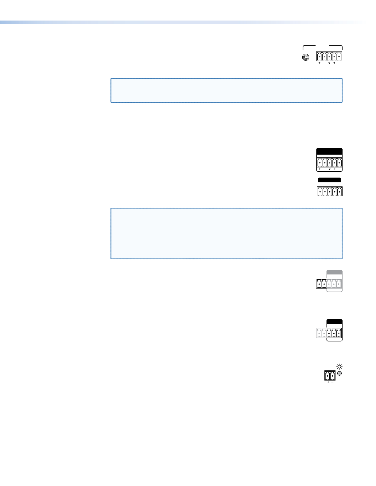
RS-232 and IR connections
Figure 6 shows how to wire the RS-232 and IR connectors.
TxRx
Tx/Rx
Pins
IR
RS-232
Tx RxTx RxG
Gnd
RxTx
Gnd
REMOTE
Tx/Rx
Pins
RS-232
ALARM
1 2 Tx RxG
Figure 6. RS-232 and IR Connector Wiring
NOTES:
• The length of exposed wires is important. The ideal length is 3/16 inch (5 mm).
• Longer bare wires can short together.
• Shorter wires are not as secure in the connectors and could be pulled out.
• Do not tin the power supply leads before installing them in the connector. Tinned
wires are not as secure in the connector and could be pulled out.
• The Remote RS-232 port is wired differently than stand-alone Extron RS-232 ports.
TxRx Gnd
12
Page 19

FOX II DP Transmitter and Receiver • Installation and Operation
Audio connections
Sleeve ( )
Ring (-)
Tip (+)
3.5 mm Stereo Plug Connector
(balanced)
Unbalanced Stereo Input
Balanced Stereo Input
Do not tin the wires!
Tip
Ring
Tip
Ring
LR
Sleeves
Tip
Sleeve
Sleeve
Tip
LR
NOTE: The level of the analog audio inputs can be set via an SIS command (see
page 21) to the transmitter or using the Product Configuration Software (see
page 33).
The following table shows the audio format that is sent over the fiber connection, along with
the DisplayPort video, when a specific audio format is not specified (see the Input audio
selection SIS commands on page 22 to switch the active audio source).
Embedded
Analog Audio
DisplayPort Audio
Present Not present Embedded audio
Present Present Embedded audio
Not present Present Analog audio
Not present Not present No audio
Transmitted Audio
3.5 mm mini jack input and output connections
See figure 7 to identify the tip, ring, and sleeve when you are making connections for the
transmitter from existing audio cables. A mono audio connector consists of the tip and
sleeve. A stereo audio connector consists of the tip, ring, and sleeve.
Figure 7. Stereo Plug Audio Connector
Captive screw input connections
See figure 8 to properly wire a captive screw input connector, either audio input on the
transmitter or return audio input on the receiver.
Figure 8. Captive Screw Connector Wiring for Stereo Audio Inputs
NOTE: The length of exposed wires is important (see the first two RS-232 and IR
connector NOTES on page 12 for more information).
13
Page 20
FOX II DP Transmitter and Receiver • Installation and Operation
Audio output connector
Unbalanced Stereo Output Balanced Stereo Output
Do not tin the wires!
Tip
No Ground Here
No Ground Here
Tip
LR
Sleeves
Tip
Ring
Tip
Ring
LR
Sleeves
Do not tin the wires!
REMOTE
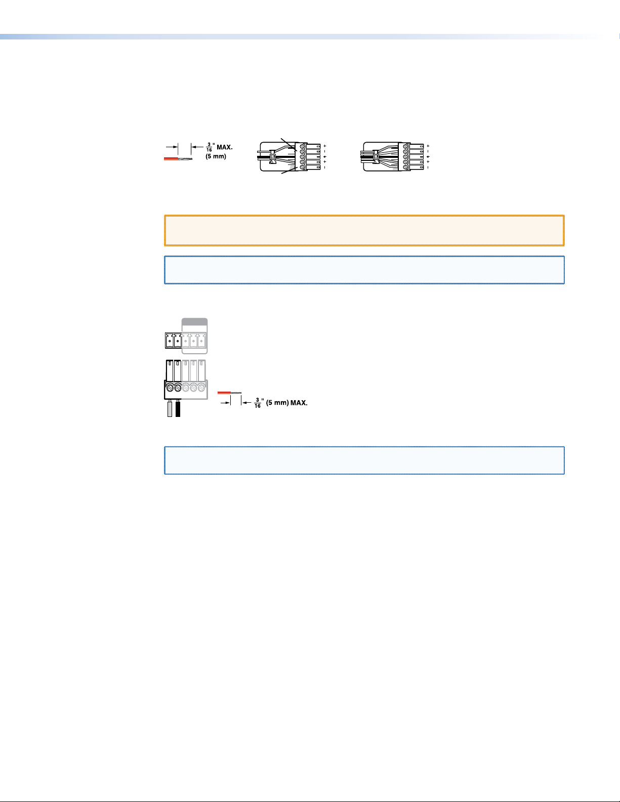
See figure 9, below, to properly wire a captive screw output connector, either audio output
on the receiver or return audio output on the transmitter. The connector is included with
transmitter, but you must supply the audio cable. Use the supplied tie-wrap to strap the
audio cable to the extended tail of the connector.
Figure 9. Captive Screw Connector Wiring for Stereo Audio Output
ATTENTION: For unbalanced audio, connect the sleeves to the ground contact.
DO NOT connect the sleeves to the negative (-) contacts.
NOTE: The length of exposed wires is important (see the first two RS-232 and IR
connector NOTES on page 12 for more information).
Alarm connection
RS-232
ALARM
1 2 Tx RxG
Pin 1 and pin 2 are
shorted together when
no light is detected.
Figure 10. Alarm Connector
NOTE: The length of exposed wires is important (see the first two RS-232 and IR
connector NOTES on page 12 for more information).
14
Page 21

FOX II DP Transmitter and Receiver • Installation and Operation
Power supply wiring
Connector
Smooth
AA
ATTENTION: Always use power supplies specified by Extron for the FOX II units. Use
of an unauthorized power supply voids all regulatory compliance certification and may
cause damage to the supply and the unit.
Figure 11 shows how to wire the power connector.
Ridges
SECTION A–A
Power Supply
Output Cord
Tie Wrap
Captive Screw
3
5
Figure 11. Power Connector Wiring
ATTENTION:
• This product is intended to be supplied by a Listed Power Unit marked “Class 2”
or “LPS,” rated 12 VDC, 2.0 A minimum. Always use power supplies supplied by
or specified by Extron. Use of an unauthorized power supply voids all regulatory
compliance certification and may cause damage to the supply and the end
product.
• Unless otherwise stated, the AC/DC adapters are not suitable for use in air handling
spaces or in wall cavities.
• The installation must always be in accordance with the applicable provisions of
National Electrical Code ANSI/NFPA 70, article 75 and the Canadian Electrical
Code part 1, section 16. The power supply shall not be permanently fixed to a
building structure or similar structure.
• Power supply voltage polarity is critical. Incorrect voltage polarity can damage the
power supply and the unit. The ridges on the side of the cord (figure 11) identify the
power cord negative lead.
To verify the polarity before connection, plug in the power supply with no load and check the
output with a voltmeter.
CAUTION: Electric shock hazard — The two power cord wires must be kept
separate while the power supply is plugged in. Remove power before wiring.
ATTENTION: The length of exposed wires is important (see the first two RS-232 and
IR connector NOTES on page 12 for more information).
Use the supplied tie wrap to strap the power cord to the extended tail of the connector.
Alternatively, an optional Extron PS 124 Universal 12 VDC Power Supply can power multiple
Extron 12 VDC devices using only one AC power connector.
15
Page 22

FOX II DP Transmitter and Receiver • Installation and Operation
Indications and Operation
Transmitter Indications
1
CONFIG
Figure 12. FOX II DP Transmitter Front Panel Features
a (power) indicator — Indicates that power is applied to the unit.
b Video LEDs —
Signal LED — Lights when the transmitter detects an active signal on its video input.
HDCP LED — Lights when the input signal is HDCP encrypted.
c Audio LEDs —
Input LED — Lights when the transmitter either:
• Detects a low level audio signal for a short period of time on the analog input. It
returns to unlit if the audio signal drops below the minimum threshold for a short
period of time.
• Detects embedded audio.
Return Out LED — Lights when the transmitter detects a signal on its Return Audio
Output connector.
32
VIDEO AUDIO
SIGNAL
HDCP
INPUT
RETURN OUT
Receiver Indications
4
CONFIG
Figure 13. FOX II DP Receiver Front Panel Features
5 6
VIDEO AUDIO
SIGNAL
HDCP
OUTPUT
RETURN IN
d (power) indicator — Indicates that power is applied to the unit.
e Video LEDs —
Signal LED — Lights when an active DisplayPort signal is detected on the fiber input of
the receiver.
HDCP LED — Lights when the input video signal detected on the fiber input is HDCP
encrypted.
f Audio LEDs —
Output LED — Lights on the receiver when the transmittereither:
• Detects a low level audio signal for a short period of time on the analog input. It
returns to unlit if the audio signal drops below the minimum threshold for a short
period of time.
• Detects embedded audio.
Return In LED — Lights when the receiver detects a signal on its Return Audio Input
connector.
16
Page 23

FOX II DP Transmitter and Receiver • Installation and Operation
Operation
After the transmitter, all receivers, and their connected devices are powered up, the system
is fully operational. If any problems are encountered, verify that the cables are routed and
connected properly, and that all display devices have identical resolutions and refresh rates.
If your problems persist, call the Extron S3 Sales & Technical Support Hotline. See the
contact numbers on the last page of this guide for the Extron office nearest you.
To take advantage of the various adjustments and test patterns available in the FOX II DP,
you need to connect a computer or other USB-capable device to the front panel
Configuration port or a RS-232 capable device to the rear panel Remote RS-232 port on
the unit to be addressed. Operate the connected device using either SIS commands or the
Product Configuration Software (see Remote Control on page 18).
17
Page 24

FOX II DP Transmitter and Receiver • Remote Control
Remote Control
This section describes the remote control operation of the FOX II DP transmitter and
receiver, including:
• Simple Instruction Set Control
• Product Configuration Software
The transmitter and receiver each have a front panel Configuration port, a mini USB jack
(see item k on page 9 and item t on page 12) and a rear panel Remote RS-232
port, a 3-pole captive screw connector (see RS-232 and IR connections on page 12).
Any of these ports can be connected to a host device such as a computer running the
HyperTerminal or DataViewer utility, or a control system to make serial control of the
transmitter and receiver possible.
The protocol for all ports is as follows:
• 9600 baud • no parity • 8 data bits
• 1 stop bit • no flow control
NOTE: RS-232 commands and Product Configuration Software functions are
transmitter- or receiver-specific or may have different responses depending on the
unit connected. You must connect to the appropriate device for the command or
function to work properly or to get the expected response.
Simple Instruction Set Control
Host-to-Unit Instructions
SIS commands consist of one or more characters per field. No special characters are
required to begin or end a command character sequence. When a command is valid, the
unit executes the command and sends a response to the host device. All responses from
the unit to the host end with a carriage return and a line feed (CR/LF = ]), which signals the
end of the response character string. A string is one or more characters.
18
Page 25

FOX II DP Transmitter and Receiver • Remote Control
Unit-initiated Messages
When a local event, such as an equipment power-up, occurs, the unit responds by sending
a message to the host. The unit-initiated messages are listed below:
(c) Copyright 20nn, Extron Electronics FOX II T DP, Vx.xx, 60-nnnn-xx
- or -
(c) Copyright 20nn, Extron Electronics FOX II R DP, Vx.xx, 60-nnnn-xx
The connected unit issues the appropriate copyright message (above) when it first
powers on. Vx.xx is the firmware version number; 60-nnnn-xx is the part number of the
connected unit.
Reconfig
The unit sends the Reconfig message whenever the video input signal to the transmitter is
changed.
1Lnkn•2Lnkn•Vidn•Audn•XX•Tx
- or -
1Lnkn•2Lnkn•Vidn•Audn•XX•Rx
The unit sends the status message whenever a change in the fiber link and video
connection occurs. n is the connection status, where 0 = link or input not detected and
1 = link or input detected. XX = either SM (singlemode) or MM (multimode).
EDidMdrnn
The unit sends the EDID Minder change message whenever a change in the position of the
transmitter front panel DDC hex switch occurs.
Hplg2
The unit sends the Hot plug message whenever the DisplayPort connector is either plugged
in or unplugged.
]
]
]
]]
]]
]
]
Error Responses
When the unit receives a valid SIS command, it executes the command and sends a
response to the host device. If the unit is unable to execute the command because the
command is invalid or it contains invalid parameters, the unit returns an error response to
the host. The error response codes are:
E10 - Invalid command
E13 - Invalid parameter
E14 - Invalid command for this configuration
19
Page 26

FOX II DP Transmitter and Receiver • Remote Control
ASCII to Hex Conversion Table
•
Space
Using the Command and Response Tables
The command and response table for the transmitter begins on the next page. The
command and response table for the receiver begins on page 24. Uppercase and lower
case letters are acceptable in the command field except where indicated for the audio level
(gain and attenuation) commands. Symbols throughout the table represent variables in the
command and response fields. Examples are shown throughout the tables. The ASCII to
HEX conversion table below is for use with the command and response tables.
Symbol Definitions for Transmitter SIS Commands
] = CR/LF (carriage return/line feed)
} = Carriage return (no line feed)
| = Pipe (can be used interchangeably with the } character)
= Space (hard) character
•
E = Escape key (hex 1B)
W = Can be used interchangeably with the E character
X! = EDID resolution See the table on page 21. All resolutions are at the 60 Hz refresh rate.
X@ = Save EDID source 1 = transmitter loop-through display 2 = receiver output display
X# = Video and sync mute status 0 = mute off 1 = video mute on 2 = video and sync mute
X$ = Audio gain adjustment range 00 to 10
X% = Audio level adjustment range –18 to +10 (in 1.0 dB steps)
X^ = Audio attenuation adjustment range 00 to 18
X& = Video delay 0 = 0 second
(0 plus six steps at 0.25 seconds per step) 1 = 0.25 second 3 = 0.75 second 5 = 1.25 second
2 = 0.5 second (default) 4 = 1.0 second 6 = 1.5 second
X* = Audio input for transmission 0 = Auto 2 = Analog audio
1 = Digital (embedded DisplayPort) audio
X( = Audio output 0 = DisplayPort and analog 1 = DisplayPort only 2 = Analog only
X1) = On and off status 0 = off 1 = on
X1! = Color bars test pattern 0 = Off (default) 2 = 720p at 60 Hz
1 = 720p at 50 Hz 3 = 1080p at 60 Hz
X1@ = Transmitter name
X1# = Link and input status 0 = link or input not detected 1 = link or input detected
X1$ = Input HDCP signal 0 = no source detected 2 = source detected but no HDCP present
1 = source detected with HDCP
X1% = Loop-through display 0 = no sink device connected 2 = sink device detected, but not HDCP compliant
1 = sink device detected and HDCP compliant
X1^ = Internal temperature nnnF•nnC
X1& = Transmission mode SM = singlemode MM = multimode
X1* = Firmware version v.vv
X1( = Frequency nnn.n
X2) = Optical module manufacturer Up to 16 alphanumeric characters
X2! = Tx or Rx power xx.x dBm
X2@ = Operating temp of module nnn.n
X2# = EDID switch position 00 (0 hex) through 15 (F hex) (see item j and the table on page 9)
20
Page 27

FOX II DP Transmitter and Receiver • Remote Control
Command and Response Table for Transmitter SIS Commands
Command SIS Command
(host to unit)
Response
(unit to host)
Additional description
EDID Minder Resolution
Set the EDID resolution
Example:
View the EDID resolution
Save an EDID
EAX!
E
A23EDID
E
AEDID
ESX@
}
EDID
}
} X!]
}
EDID
X!]
EdidA
EdidA23
X@]
EdidS
]
Set the EDID resolution to X!.
Set the EDID resolution to 1280x768 with
embedded 2-channel audio.
Save the EDID from the X@ connection to the
memory location.
Video and sync mutes
Mute output, video only
Mute output, video and sync
Unmute output
Show video mute status
1B
2B
0B
B
Vmt1
Vmt2
Vmt0
X#]
]
]
]
Mute the video output, display black video.
Mute the video and sync outputs.
Output video.
Video mute status is X#.
Analog audio input gain and attenuation
NOTE: The set gain (G) and set attenuation (g) commands are case sensitive. The increment level, decrement level, and show level are
not case sensitive.
Set input audio gain to a +dB
value
Example:
Set input audio attenuation to
a -dB value
Increment input level
Example:
Decrement input level
Show input level
X$
G Aud
2G
X^
g Aud
+G
+G
–G
G
Aud2
Aud
Aud3
Aud
X%]
X%]
]
X%]
X%]
]
X%]
Set the input level to X% dB (gain).
Set the input level to +2 dB (gain).
Set the input level to X% dB (attenuation).
Increase the audio level by 1 dB.
Increment the input level from +2 dB to +3 dB.
Decrease the audio level by 1 dB.
KEY: X! = EDID resolution See the table below.
X!
Value
X!
Value
X!
Value
X!
Value
X!
Value
Video only (no embedded audio)
800x600
01
1024x768
02
1280x720
03*
1280x768
04
Video and embedded 2-channel audio
800x600
20
1024x768
21
1280x720
22
1280x768
23
05
06
07
08
24
25
26
27
1280x800
1280x1024
1366x768
1366x768
1280x800
1280x1024
1360x768
1366x768
09
10
11
12
28
29
30
31
1400x1050
1440x900
1600x900
1600x1200
1400x1050
1440x900
1600x900
1600x1200
13
14
15
16
32
33
34
35
1680x1050
1920x1080
1920x1200
2048x1080
1680x1050
1920x1080
1920x1200
2048x1080
17
18
19
36
37
38
2048x1536
2560x1440
2560x1600
2048x1536
2560x1440
2560x1600
Connected display or a customer-saved value
Source
X!
Display connected to the receiver output connector
39
Display connected to the transmitter loop-through connector
40
User memory
41
* Default
X@ = Save EDID source 1 = Transmitter loop-through 2 = Receiver output
X# = Video and sync mute status 0 = off 2 = video and sync mute on
1 = video mute on
X$ = Audio gain adjustment range 00 to 10
X% = Audio level adjustment range -18 to +10 (in 1.0 dB steps)
X^ = Audio attenuation adjustment range 00 to 18
21
Page 28

Command/response table for Transmitter SIS commands (continued)
FOX II DP Transmitter and Receiver • Remote Control
Command SIS Command
(host to unit)
Video shutdown delay
NOTES:
• The Set Video Delay command blanks the digital video for a specified time to help sink devices correctly detect an AV rate change.
• Only video is blanked; embedded audio is not muted.
Set delay
Example:
View delay
Audio input format
NOTE: This command selects the audio input that is transmitted to the receiver.
Select auto
Select digital audio
Select analog audio
Show audio selection
Audio mute (DisplayPort Loop-through and Return Out)
Mute the audio
Example:
Unmute the audio
Show audio mute status
NOTE: 0 is not a valid X( value for the show audio mute status command.
Input reports as an HDCP authorized device
HDCP authorized device on
HDCP authorized device off
View HDCP authorized
device status
Color bars test pattern
NOTE: The transmitter generates the color bars test pattern and sends it to the receiver. You must have the transmitter-Tx-to-receiver-Rx
fiber cable connected for the receiver to output the selected test pattern. The test pattern turns off if power is removed.
Output color bars test pattern
Turn test pattern off
Show test pattern status
Transmitter name
Assign a name to the device
Reset device name to default
View the device name
X&
# Dly
3*
3*3#
3#
E
E
E
E
X(
*1Z AmtX(*1
1*1Z
X(
*0Z AmtX(*0
X(
*Z
E
E
E
EX1!
E
E
}
I0AFMT
}
I1AFMT
}
I2AFMT
} X*]
IAFMT
}
E1HDCP
}
E0HDCP
} X1)]
EHDCP
}
Test
}
0Test
} X1!]
Test
EX1@CN}
E
}
•CN
ECN} X1@]
Response
(unit to host)
X&]
]
Dly3
X&]
]
AfmtI0
]
AfmtI1
]
AfmtI2
]
]
Amt1*1
]
X1)]
]
HdcpE1
]
HdcpE0
X1!]
Test
]
Test0
X1@]
Ipn•
X1@]
Ipn•
Additional description
Delay video by an interval of X&.
Delay video by an interval of 0.75 seconds
(3 x 0.25 seconds).
Transmit the digital audio embedded in the
DisplayPort input, if detected, otherwise transmit
the analog audio.
Transmit the digital audio embedded in the
DisplayPort input.
Transmit the analog audio input.
Show the selected format.
Silence the DisplayPort Loop-through audio,
Return Out audio, or both of the transmitter.
Silence the DisplayPort Loop-through audio.
The transmitter outputs Return Out audio.
Mute status of X( audio is
Set the transmitter as an HDCP-authorized device.
Set the transmitter as not an HDCP-authorized
device.
Show HDCP authorized device status.
Set the transmitter to output the color bars test
pattern to the receiver.
and rate.
Set the transmitter to output the input video to
the receiver (no test pattern is selected).
Name the transmitter
Name the transmitter “FOX II T DP“.
X1)
.
X1!
defines the resolution
X1@
.
KEY: X& = Video delay (0 plus six steps at 0.25 seconds per step
1 = 0.25 second 4 = 1.0 second
2 = 0.5 second (default) 5 = 1.25 second
3 = 0.75 second 6 = 1.5 second
X* = Audio input for transmission
X(
= Audio output (DisplayPort Loop-through and Return Out) 0 = DisplayPort and analog 2 = Analog only
) 0 = 0 second
0 = Auto
1 = Digital (embedded DisplayPort) audio
2 = Analog audio
1 = DisplayPort only
X1) = HDCP and mute on or off status 0 = Off 1 = On
X1! = Color bars test pattern
0 = Off (default) 2 = 720p at 60 Hz
1 = 720p at 50 Hz 3 = 1080p at 60 Hz
X1@ = Transmitter name Up to 24 alphanumeric characters and hyphen (–)
22
Page 29

Command/response table for Transmitter SIS commands (continued)
FOX II DP Transmitter and Receiver • Remote Control
Command SIS Command
(host to unit)
Status requests
View link 1 (Tx-to-Rx) status
View link 2 (Rx-to-Tx) status
View input video status
View input audio status
View all signal status
View DisplayPort signal
status
View HDCP status
View temperature
1S
2S
3S
4S
5S
6S
7S
20S
Information requests
Information request
Show firmware version
Example:
Request part number
Input sync detection
Request SFP status
Request switch position
I
Q
Q
N
E
} X1(
1LS
40S
E
STAT
}
Resets
Reset audio
System reset
EZA}
E
ZXXX
}
Response
(unit to host)
X1#]
X1#]
X1#]
X1#]
X1#
SigI
SigI
HDCPI
X1^F•X1^C]
1Lnk
X1*]
1.23
60–
X2)•X2!
EdidMdr
Zpa
Zpx
•SigO
X1#
•SigO
X1$
X1#
•2Lnk
]
nnnn–nn
horizontal
Tx
•
]
]
•HDCPO
,
X2!
X2#]
]
X1(
Rx
X1#
•HDCPI
X1#]
X1%]
X1#
•Vid
vertical
X2@]
•
Additional description
X1$
Report the status of the DisplayPort input,
DisplayPort output, HDCP encoding on the input,
and HDCP encoding on the output.
Report the status of the DisplayPort input and
DisplayPort output.
Report the status of the HDCP encoding on the
input and HDCP encoding on the output.
Show temperature in degrees Fahrenheit and
Celsius.
X1#
•Aud
The unit responds with the current status
(signal detected) of optical link 1, optical link 2,
the video input, and the audio link; the fiber optic
transmission mode (singlemode or multimode);
and the device type (
The factory-installed firmware version is 1.23
(sample value only).
See the Extron website, www.extron.com, for
part numbers.
]
Shows horizontal frequency in kHz and vertical
frequency in Hz. 000.0,000.0 if no signal is
detected.
Reset audio setting to default levels (0 dB gain).
Reset all settings to factory defaults.
•HDCPO
X1#•X1&
X1%]
•Tx
]
Tx).
KEY: X1# = Link status 0 = light or signal input not detected
1 = light or signal detected
X1$ = Input HDCP signal 0 = no source detected
1 = source detected with HDCP
2 = source detected but no HDCP present
X1% = Loop-through display 0 = no sink device connected
1 = sink device detected and HDCP compliant
2 = sink device detected, but not HDCP compliant
X1^ = Temperature nnn
X1& = Transmission mode SM = singlemode MM = multimode
X1* = Firmware version v.vv
X1( = Sync frequency xxx.x (frequency in kHz [H] or Hz [V])
X2)
= Optical module manufacturer Up to 16 alphanumeric characters
X2!
= Tx or Rx power xx.x dBm
X2@
= Operating temp of module nnn.n
X2# = EDID switch position 00 (0 hex) through 15 (F hex) (see item 10 and the table on page 9)
23
Page 30

FOX II DP Transmitter and Receiver • Remote Control
Symbol Definitions for Receiver SIS Commands
] = CR/LF (carriage return/line feed)
} = Carriage return (no line feed)
| = Pipe (can be used interchangeably with the } character)
= Space (hard) character
•
E = Escape key (hex 1B)
W = Can be used interchangeably with the E character
X# = Video and sync mute status 0 = off 2 = video and sync mute on
1 = video mute on
X$ = Audio gain adjustment range 00 to 10
X% = Audio level adjustment range –18 to +10 (in 1.0 dB steps)
X^ = Audio attenuation adjustment range 00 to 18
X& = Video delay 0 = 0 second
(0 plus six steps at 0.25 seconds per step) 1 = 0.25 second 3 = 0.75 second 5 = 1.25 second
2 = 0.5 second (default) 4 = 1.0 second 6 = 1.5 second
X( = Audio output 0 = DisplayPort and analog 1 = DisplayPort only 2 = Analog only
X1) = On and off status 0 = off 1 = on
X1@ = Receiver name
X1# = Link and input status 0 = link or input not detected 1 = link or input detected
X1$ = Input HDCP signal 0 = no source detected 2 = source detected but no HDCP present
1 = source detected with HDCP
X1% = Loop-through display 0 = no sink device connected 2 = sink device detected, but not HDCP compliant
1 = sink device detected and HDCP compliant
X1^ = Internal temperature nnnF•nnC
X1& = Transmission mode SM = singlemode MM = multimode
X1* = Firmware version v.vv
X1( = Frequency nnn.n
X2) = Optical module manufacturer Up to 16 alphanumeric characters
X2! = Tx or Rx power xx.x dBm
X2@ = Operating temp of module nnn.n
X2$ = Audio output level 0 = Consumer level (-10 dBV) 1 = Professional level (+4 dBu)
Command and Response Table for Receiver SIS Commands
Command SIS Command
(host to unit)
Video and sync mutes
Mute output, video only
Mute output, video and sync
Unmute output
Show video mute status
1B
2B
0B
B
HDCP notification
Enable notification
Disable notification
View notification status
EN1HDCP} HdcpN1]
EN0HDCP} HdcpN0]
ENHDCP}
Video shutdown delay
NOTES:
• The Set Video Delay command delays the digital video to help monitors sync correctly during an input rate change.
• Only video is delayed; embedded audio is not delayed.
Set delay
Example:
View delay
X&
# Dly
3*
3*3#
3#
Response
(unit to host)
]
Vmt1
]
Vmt2
]
Vmt0
X#]
X1)]
X&]
]
Dly3
X&]
Additional description
Mute the video output, display black video.
Mute the video and sync outputs.
Output video.
Video mute status is X#.
Delay video by an interval of X&.
Delay video by an interval of 0.75 seconds
(3 x 0.25 seconds).
24
Page 31

Command/response table for Receiver SIS commands (continued)
FOX II DP Transmitter and Receiver • Remote Control
Command SIS Command
(host to unit)
Audio input gain and attenuation (for analog audio return)
NOTE: The set gain (G) and set attenuation (g) commands are case sensitive. The increment level, decrement level, and show level are
not case sensitive.
Set input audio gain to a +dB
value
Example:
Set input audio attenuation to
a -dB value
Increment input level
Example:
Decrement input level
Show input level
X$
G Aud
2G
X^
g Aud
+G
+G
–G
G
Audio output level
Set to consumer level (default)
Set to professional level
View audio output level
40*0#
40*1#
40#
Audio mute
Mute the audio
Unmute the audio
Show audio mute status
NOTE: 0 is not a valid X( value for the show audio mute status command.
X(
*1Z AmtX(*1
X(
*0Z AmtX(*0
X(
*Z
Receiver name
Assign a name to the device
Reset device name to default
View the device name
EX1@CN}
E
}
•CN
ECN} X1@]
Status requests
View link 1 (Tx-to-Rx) status
View link 2 (Rx-to-Tx) status
View input video status
View input audio status
View all signal status
View DisplayPort signal
status
View HDCP status
View temperature
1S
2S
3S
4S
5S
6S
7S
20S
Information requests
Information request
Show firmware version
Example:
Request part number
Input sync detection
Request SFP status
I
Q
Q
N
E
} X1(
1LS
40S
Response
(unit to host)
X%]
]
Aud2
X%]
X%]
Aud
]
Aud3
X%]
Aud
X%]
]
Lvl0
]
Lvl1
X2$]
]
]
X1)]
X1@]
Ipn•
X1@]
Ipn•
X1#]
X1#]
X1#]
X1#]
X1#
SigI
SigI
HDCPI
X1^F•X1^C]
1Lnk
X1*]
1.23
60–
X2)•X2!
•SigO
X1#
•SigO
X1$
X1#
•2Lnk
]
nnnn–nn
horizontal
Tx
•
•HDCPO
,
X2!
]
X1(
Rx
X1#
•HDCPI
X1#]
X1%]
X1#
•Vid
vertical
X2@]
•
Additional description
Set the input level to X% dB (gain).
Set the input level to +2 dB (gain).
Set the input level to X% dB (attenuation).
Increase the audio level by 1 dB.
Increment the input level from +2 dB to +3 dB.
Decrease the audio level by 1 dB.
Set output level to -10 dBV.
Set output level to +4 dBu.
Silence the audio output of the receiver.
The receiver outputs audio.
X1@
X1)
.
.
Mute status of X( audio is
Name the receiver
Name the receiver “FOX II R DP“.
X1$
Report the status of the DisplayPort input,
DisplayPort output, HDCP encoding on the input,
and HDCP encoding on the output.
Report the status of the DisplayPort input and
DisplayPort output.
Report the status of the HDCP encoding on the
input and HDCP encoding on the output.
Show temperature in degrees Fahrenheit and
Celsius.
X1#
•Aud
The unit responds with the current status (signal
detected) of optical link 1, optical link 2, the
video input, and the audio link; the fiber optic
transmission mode (singlemode or multimode);
and the device type (Rx).
The factory-installed firmware version is 1.23
(sample value only).
See the Extron website, www.extron.com, for
part numbers.
]
Shows horizontal frequency in kHz and vertical
frequency in Hz. 000.0,000.0 if no signal is
detected.
•HDCPO
X1#•X1&
X1%]
•Rx
]
25
Page 32

Command/response table for Receiver SIS commands (continued)
FOX II DP Transmitter and Receiver • Remote Control
Command SIS Command
(host to unit)
Resets
Reset audio
System reset
EZA}
E
ZXXX
}
Response
(unit to host)
]
Zpa
]
Zpx
Additional description
Reset the audio output to the consumer level and
return audio gain and attenuation to 0 dB.
Reset all settings to factory defaults.
26
Page 33

FOX II DP Transmitter and Receiver • Remote Control
Product Configuration Software
— OR
The Extron Product Configuration Software, which communicates with the connected
transmitter or receiver via the rear panel Remote RS-232 port or front panel Configuration
USB port of that unit, provides an easy way to operate and configure the unit.
The program is compatible with Windows 2000, Windows XP, or later. Updates to this
program can be downloaded from the Extron website.
Installing the Software
The Product Configuration Software, version 1.4 or newer, and Firmware Loader are available
on the Extron website. Download and install both programs as follows:
NOTE: Steps 1 through 6, below, are also used to download firmware update packages.
1. Visit the website www.extron.com and click the Download tab (see figure 14).
2
1
—
3
2
4
5
6
Figure 14. Downloading a Software or Firmware Package
2. Click the Software or Firmware link as appropriate to the operation you are performing.
3. Select the desired software or firmware file to download and click Download.
TIP: Jump to the nearest page of downloads by clicking the desired filtering letter.
27
Page 34

FOX II DP Transmitter and Receiver • Remote Control
4. Enter the requested personal information;
TIP: Click Remember Me to eliminate step 4 in future downloads.
5. Click Download to copy the software or firmware to your computer.
6. Cick Run to confirm that you want to run the installation.
7. For a firmware download, exit this procedure and return to Updating the Firmware
on page 37.
8. Follow the on-screen instructions. The installation creates a C:\Program Files\Extron\
Extron PCS directory, and it places the following four icons into a group folder named
“Extron Electronics\Extron Product Configuration Software:”
NOTE: C:\Program Files(x86)\ ... for Windows 7 or Windows 8.
• Check for Extron PCS Updates
• Extron PCS Help
• Extron Product Configuration Software
• Uninstall Extron Product Configuration Software
Starting the Program
Start the Extron Product Configuration Software as follows:
1. Click Start > Programs > Extron Electronics > Extron Product Configuration
Software > Extron Product Configuration Software.
The Product Configuration Software opens to the Select Connection Options screen
(see figure 15).
NOTES:
• Figure 15 shows the RS-232 and the USB radio buttons both selected. This is
for reference only; selecting one radio button deselects the other.
• The transmitter and receiver do not have Ethernet connections; the Ethernet
connection cannot be selected for these products.
1 2
4
3
5
Figure 15. Select Connection Options Screen
28
Page 35

FOX II DP Transmitter and Receiver • Remote Control
2. If this is the first use with the FOX II units, click the New tab. The program opens to
the Select Connection Options screen.
3. If necessary for a Remote RS-232 port connection, select the RS232 radio button
(see figure 15, item a on on the previous page). Proceed to step 4.
If necessary for a Configuration port connection, select the USB radio button (b).
Proceed to step 5.
4. For a Remote RS-232 connection, select the Com port to which your transmitter
or receiver is connected (c). Click Connect (e). The Product Configuration Software
displays the Status screen (figure 16 for, below, the transmitter and figure 17, on the
next page, for the receiver, both on the next page).
5. For a USB connection, select the transmitter or receiver in the USB device field (d).
Click Connect (e). The Product Configuration Software displays the Status screen
(figure 16 for the transmitter and figure 17 for the receiver).
Once connected, the Product Configuration Software consists of two tabs:
• Configuration, consisting of Status, EDID Minder (for a transmitter connection
only), and Input/Output Config(uration) screens
• Hardware, consisting of Unit Information, Device Name, and Reset Device screens
1
2
3
4
5
6
7
8
9
10
11
Figure 16. Status Screen for the Transmitter
29
Page 36

FOX II DP Transmitter and Receiver • Remote Control
1
2
3
4
5
Figure 17. Status Window for the Receiver
Using the Software
Once you have connected to a device, the Status screen (see figure 16, on the previous
page, for the transmitter and figure 17, above, for the receiver) is the default start-up screen
for the Product Configuration Software. The screen provides indications of the connection
status.
Configuration > Status window (both units)
a Fiber Rx Link indicators
Link 2 indicator (transmitter connection) — Indicates green when the transmitter
detects light on the fiber optic cable connected to the Rx port.
Link 1 indicator (receiver connection) — Indicates green when the receiver detects
light on the fiber optic cable connected to the Tx port.
b Manufacturer fields — Indicates the manufacturer of the SFP module.
6
7
8
c Tx Power fields — Indicates the power on the Tx optical module of the unit in dBm.
d Rx Power fields — Indicates the power on the Rx optical module of the unit in dBm.
e Operating Temperature — Indicates the temperature in degrees Fahrenheit and
degrees Celsius.
f Video Signal Presence indicators
Transmitter connection — Indicates green when the transmitter detects a sync signal
on its DisplayPort video input.
Receiver connection — Indicates green when the receiver detects a digital video
signal on its fiber optic input.
g Audio Signal Presence indicators
Transmitter connection — Indicates green when the transmitter detects a low level
analog audio signal for a short period or embedded audio. This indicator goes dark if
the detected analog audio signal drops below the minimum threshold for a short period.
Receiver connection — Indicates green when the receiver detects an embedded
digital or low level analog audio signal on its fiber optic input.
30
Page 37

FOX II DP Transmitter and Receiver • Remote Control
h HDCP Signal indicator — Shows a lock icon ( ) when the digital video signal has a
copyright encryption applied and shows an unlocked icon ( ) when the signal is not
copyright protected.
Configuration > Status screen
(transmitter connection only)
i Default Active Pixels and Lines fields — These fields
display the size (resolution) of the connected DisplayPort
video source.
9
10
11
j Default H Total Pixels and Total Lines fields — These
fields display the total size of the connected DisplayPort video source.
k Horizontal Frequency and Vertical Frequency fields — These fields display the
horizontal frequency of the digital video input in kHz and vertical frequency in Hz.
31
Page 38

FOX II DP Transmitter and Receiver • Remote Control
Configuration > EDID Minder screen (transmitter connection only)
The EDID Minder screen (see figure 18, below) provides controls for you to tailor the EDID
that is provided to the transmitter. Select this screen by clicking the EDID Minder subtab
from either the Status or Input/Output Configuration screen or Configuration > EDID
Minder from one of the Hardware screens.
NOTE: The transmitter front panel EDID Select rotary switch must be in the 1 position
for most of the EDID Minder window to be available for operation. When the switch is
in other positions, only the Input field (e) and the following is displayed:
4
3
2
1
5
Figure 18. EDID Minder Screen (Transmitter Connection Only)
Click an EDID box in the Available EDID (a), Connected Outputs (b), or
Favorites (
) panels to select (highlight in yellow) the EDID identified by that box.
c
If desired, drag and drop an EDID box into the Favorites panel.
If desired, reduce the number of EDID boxes displayed by selecting a filter in one of four
categories (panels) (d): Resolution, Refresh Rate, Video Format, and Audio Format.
The Input panel (e) displays the resolution, rate, video type, and embedded audio
format of the DisplayPort input.
32
Page 39

FOX II DP Transmitter and Receiver • Remote Control
Configuration > Input/Output Configuration screen
The Input/Output Configuration screen allows you to set the input and output option
features of the transmitter (see figure 19, below) and receiver (see figure 20, on page 35).
Select this screen by clicking the Input/Output Config subtab from either the Status or
EDID Minder screen or Configuration > Input/Output Config from one of the Hardware
screen.
Transmitter Input/Output Configuration screen
1
2
3
4
5
Figure 19. Input/Output Configuration Screen for the Transmitter
6
7
8
a HDCP Authorized checkbox — Select for the transmitter to act as an
HDCP-authorized device. Deselect if you do not desire the transmitter to
act as an HDCP-authorized device. An HDCP authorized device allows an HDMI source
to output HDCP-encrypted video.
A non-authorized setting is useful for video sources that always encrypt their output if
the connected device (the transmitter in this example) is HDCP capable. If the display
connected to the receiver is not HDCP compliant, this automatic encryption would
result in no display.
b HDCP Notification radio buttons — Select either the Green or Black
radio button to select how the transmitter displays HDCP notification on a
monitor connected to its Loop-through output port.
The HDCP notification function in the transmitter enables a connected display to show a
green or black screen if the transmitted video is HDCP encrypted, and the display is not
HDCP capable.
33
Page 40

FOX II DP Transmitter and Receiver • Remote Control
c Video Mute button — Click this button to toggle the video mute on and off
for the transmitter Loop-through output port. Video mute sends black video
while maintaining sync timings from the input video signal. Embedded audio continues
to be output.
d Sync Mute button — Click this button to toggle the video mute on and off
for the transmitter Loop-through output port. Sync mute disables the sync
output, allowing the display to go blank and, eventually (depending on the timeout
parameters set in the connected display) go into standby or sleep mode. Embedded
audio is also muted.
NOTE: Video Mute cancels Sync Mute and Sync Mute cancels Video Mute.
e Video Test Pattern drop-down box — Click the Video Test
Pattern drop-down box to select from the available test patterns,
shown at right, for the transmitter to send to the receiver on the
fiber cable. Or select Off to transmit the digital video input on the
DisplayPort input port.
f Audio Format radio buttons —
Auto Detect radio button — Transmit the embedded
digital audio if detected, otherwise transmit analog
audio.
Digital radio button — Transmit the embedded digital audio.
Analog radio button — Transmit the analog audio.
g Analog Input Gain slide control — Click and slide the Analog Input
Gain slide control control to vary to select the input audio gain or
attenuation value on the analog input only, from -18 dB to +10 dB in
1.0 dB increments.
NOTE: As an alternative, you can also either:
• Click the up arrow ( ) and down arrow ( ) buttons to step the
level up and down.
• Click and highlight the value displayed in the dB field ( ) and
type in the desired numeric level.
h DisplayPort Mute button — Click this button to mute and unmute the
audio embedded in the DisplayPort loop-through output.
34
Page 41

FOX II DP Transmitter and Receiver • Remote Control
Receiver Input/Output Configuration screen
6
1
2
3
4
5
Figure 20. Input/Output Configuration Screen for the Receiver
7
a HDCP Notification radio buttons — Select either the Green or Black
radio button to select how the receiver displays HDCP notification on a
monitor connected to its DisplayPort Output port.
b Video Shutdown Delay drop-down box — Click the Video Shutdown
Delay drop-down box to set the video shut down delay. This setting
delays the digital video to help the monitor sync correctly during an
input rate change. Only video is delayed; embedded audio is not
delayed.
c Video Mute button — Click this button to toggle the video mute on and off
for the receiver DisplayPort output port. Video mute sends black video while
maintaining sync timings from the input video signal. Embedded audio continues to be
output.
d Sync Mute button — Click this button to toggle the video mute on and off
for the receiver DisplayPort output port. Sync mute disables the sync output,
allowing the display to go blank and, eventually (depending on the timeout parameters
set in the connected display) go into standby or sleep mode. Embedded audio is also
muted.
NOTE: Video Mute cancels Sync Mute and Sync Mute cancels Video Mute.
35
Page 42

FOX II DP Transmitter and Receiver • Remote Control
e Tx Output radio buttons — Select among the available radio buttons to
define the function of the receiver Tx LC connector; either:
Enable Fiber Out — Routing RS-232 over fiber to the transmitter
Disable Fiber Out — No function
NOTE: The disable fiber out function is primarily used and recommended when the
transmitted signal is routed via a FOX 500 DA6 and the receiver is connected to
any of outputs 2 through 6 on the FOX DA.
f Return Audio Input Gain slide control — Click and slide the
Return Audio Input Gain slide control to vary to select the input
audio gain or attenuation value of the audio returned to the transmitter,
from -18 dB to +10 dB in 1.0 dB increments.
NOTE: As an alternative, you can also either:
• Click the up arrow ( ) and down arrow ( ) buttons to step the
level up and down.
• Click and highlight the value displayed in the dB field ( )
and type in the desired numeric level.
g Mute buttons — Click the Mute buttons to toggle the following mute
functions on and off:
DisplayPort Mute — Mute the signal on the DisplayPort Output port.
Analog Mute — Mute the signals on both analog audio output ports.
Mute All — Mute the signals on the DisplayPort Output port and both analog audio
output ports.
Hardware > Unit Information screen (both units)
The Unit Information screen (see figure 21) provides general information about the
connected unit. Select this screen by clicking the Unit Information subtab from either the
Device Name or Reset Device screen or Hardware > Unit Information from one of the
Configuration screens.
Figure 21. Unit Information Screen
36
Page 43

FOX II DP Transmitter and Receiver • Remote Control
Hardware > Device Name screen (both units)
The Device Name screen provides controls to allow you to
assign a locally-assigned name to the unit or to reset the
unit to the default name. Select this screen by clicking the
Device Name subtab from either the Unit Information or
Reset Device screen or Hardware > Device Name from one
of the Configuration screens.
The Apply and Cancel buttons become selectable when
you have entered a name in the Enter a device name: field.
Hardware > Reset Device screen (both units)
The Reset Device screen provides a button to command a reset of
the connected unit. Reset returns all settings to their default values.
Select this screen by clicking the Reset Device subtab from either
the Unit Information or Device Name screen or Hardware > Reset
Device from one of the Configuration screens.
Updating the Firmware
The Product Configuration Software can call the Firmware Loader utility, which provides a
way to replace the firmware that is coded on the control board of the transmitter or receiver
without taking the unit out of service.
NOTE: Upgrading the firmware does not overwrite the current configuration.
Update the unit firmware as follows:
1. Perform steps 1 through 6 of Installing the Software, on page 27, to download the
firmware upgrade from the Extron website, www.extron.com.
2. Click Run in the File Download and Security Warning dialog boxes (see figure 22 on the
next page). The PC downloads the firmware update from the Extron website and starts
the Extron Installation Program to extract the firmware file.
3. Click Next. The program extracts the firmware files and places them in a folder
identified in the InstallShield Wizard window.
ATTENTION: The firmware file must have an .s19 extension. Other file types can
cause the unit to stop functioning.
NOTES:
• Note the folder to which the firmware file is saved. When downloaded
from the Extron website, the firmware is placed in a subfolder of:
• Windows 7 or Windows 8: C:\Program Files (x86)\Extron\Firmware.
• Older versions: C:\Program Files\Extron\Firmware.
• The original factory-installed firmware is permanently available on the unit. If
the attempted firmware upload fails, the unit reverts to the factory-installed
firmware.
4. Click Finish to exit the program.
5. Connect the computer to the front panel Configuration port (see page 9 [transmitter] or
page 12 [receiver]) of the unit to be updated.
37
Page 44

FOX II DP Transmitter and Receiver • Remote Control
Where
2
2
3
Folder
Firmware is
Installed.
4
Figure 22. Downloading Firmware Upgrade Files
38
Page 45

FOX II DP Transmitter and Receiver • Remote Control
6. Start the Product Configuration Software and connect to the unit (see Starting the
Program, steps 1, 2, 3, and 5, starting on page 28.
7. Click Tools > Update firmware. The software asks you to confirm that you want to
disconnect it from the unit (see figure 23).
8. Click Continue. The Product Configuration Software disconnects itself from the unit
and calls the Firmware Loader utility in the background. The Update Firmware dialog
box appears.
8
9
10
10
11
Figure 23. Updating Firmware
9. Click Browse. The Open dialog box opens.
10. Navigate to the folder where you saved the firmware upgrade file (see figure 23, above).
Select the file and click Open. The Update Firmware dialog box returns to the top.
39
Page 46

FOX II DP Transmitter and Receiver • Remote Control
11. Click Update.
The software advises you that you are about to reprogram the unit firmware. Click OK to
continue.
The Firmware Loader utility tests the
connection, installs the update, and then
verifies the firmware.
At the conclusion of the process, the utility reports Upload Complete.
12. Click Close. The Product Configuration Software window returns to the front.
13. Click the in the connection tab to completely disconnect the program from the unit
and then reconnect the program as described in Starting the Program, beginning at
step 3 on page 29.
40
Page 47

FOX II DP Transmitter and Receiver • Unit Mounting
Unit Mounting
Mounting the Units
ATTENTION: Installation and service must be performed by authorized personnel only.
Either of the 1-inch high, half-rack width units can be placed on a tabletop or mounted on a
rack shelf, or under or through a desk or other furniture. The receiver can be mounted to a
projector bracket.
Tabletop Use
Affix the included rubber feet to the bottom of the unit and place it in any convenient
location.
Mounting kits
Mount the unit using any compatible rack, projector, or furniture mounting kit, listed on the
Extron website (www.extron.com), in accordance with the directions included with the kit.
For rack shelf mounting, also see “UL Rack-Mounting Guidelines,“ below.
Rack-Mounting UL Guidelines
The following Underwriters Laboratories (UL) guidelines pertain to the installation of the
FOX II DP unit into a rack.
• Elevated operating ambient — If installed in a closed or multi-unit rack assembly,
the operating ambient temperature of the rack environment may be greater than room
ambient. Therefore, consider installing the equipment in an environment compatible with
the +122 °F (+50 °C) maximum ambient temperature (Tma) specified by Extron.
• Reduced air flow — Installation of the equipment in a rack should be such that the
amount of air flow required for safe operation of the equipment is not compromised.
• Mechanical loading — Mounting of the equipment in the rack should be such that a
hazardous condition is not achieved due to uneven mechanical loading.
• Circuit overloading — Consideration should be given to the connection of the
equipment to the supply circuit and the effect that overloading of the circuits might have
on overcurrent protection and supply wiring. Appropriate consideration of equipment
nameplate ratings should be used when addressing this concern.
• Reliable earthing (grounding) — Reliable earthing of rack-mounted equipment
should be maintained. Particular attention should be given to supply connections other
than direct connections to the branch circuit (such as the use of power strips).
41
Page 48

Extron Warranty
Extron Electronics warrants this product against defects in materials and workmanship for a period of three years
from the date of purchase. In the event of malfunction during the warranty period attributable directly to faulty
workmanship and/or materials, Extron Electronics will, at its option, repair or replace said products or components,
to whatever extent it shall deem necessary to restore said product to proper operating condition, provided that it is
returned within the warranty period, with proof of purchase and description of malfunction to:
USA, Canada, South America,
and Central America:
Extron Electronics
1230 South Lewis Street
Anaheim, CA 92805
Japan:
Extron Electronics, Japan
Kyodo Building, 16 Ichibancho
Chiyoda-ku, Tokyo 102-0082
Japan
U.S.A.
Europe and Africa:
Extron Europe
Hanzeboulevard 10
3825 PH Amersfoort
The Netherlands
China:
Extron China
686 Ronghua Road
Songjiang District
Shanghai 201611
China
Asia:
Extron Asia Pte Ltd
135 Joo Seng Road, #04-01
PM Industrial Bldg.
Singapore 368363
Middle East:
Extron Middle East
Dubai Airport Free Zone
F12, PO Box 293666
United Arab Emirates, Dubai
Singapore
This Limited Warranty does not apply if the fault has been caused by misuse, improper handling care, electrical
or mechanical abuse, abnormal operating conditions, or if modifications were made to the product that were not
authorized by Extron.
NOTE: If a product is defective, please call Extron and ask for an Application Engineer to receive an RA (Return
Authorization) number. This will begin the repair process.
USA: 714.491.1500 or 800.633.9876 Europe: 31.33.453.4040
Asia: 65.6383.4400 Japan: 81.3.3511.7655
Units must be returned insured, with shipping charges prepaid. If not insured, you assume the risk of loss or damage
during shipment. Returned units must include the serial number and a description of the problem, as well as the
name of the person to contact in case there are any questions.
Extron Electronics makes no further warranties either expressed or implied with respect to the product and its quality,
performance, merchantability, or fitness for any particular use. In no event will Extron Electronics be liable for direct,
indirect, or consequential damages resulting from any defect in this product even if Extron Electronics has been
advised of such damage.
Please note that laws vary from state to state and country to country, and that some provisions of this warranty may
not apply to you.
Extron Headquarters
+1.800.633.9876 (Inside USA/Canada Only)
Extron USA - West Extron USA - East
+1.714.491.1500 +1.919.850.1000
+1.714.491.1517 FAX +1.919.850.1001 FAX
Extron Europe
+800.3987.6673
(Inside Europe Only)
+31.33.453.4040
+31.33.453.4050 FAX
© 2014 Extron Electronics All rights reserved. www.extron.com
Extron Asia
+800.7339.8766
(Inside Asia Only)
+65.6383.4400
+65.6383.4664 FAX
Extron Japan
+81.3.3511.7655
+81.3.3511.7656 FAX
Extron China
+4000.398766
Inside China Only
+86.21.3760.1568
+86.21.3760.1566 FAX
Extron Middle East
+971.4.299.1800
+971.4.299.1880 FAX
Extron Korea
+82.2.3444.1571
+82.2.3444.1575 FAX
Extron India
1800.3070.3777
Inside India Only
+91.80.3055.3777
+91.80.3055.3737 FAX
 Loading...