

Page 1
User Guide
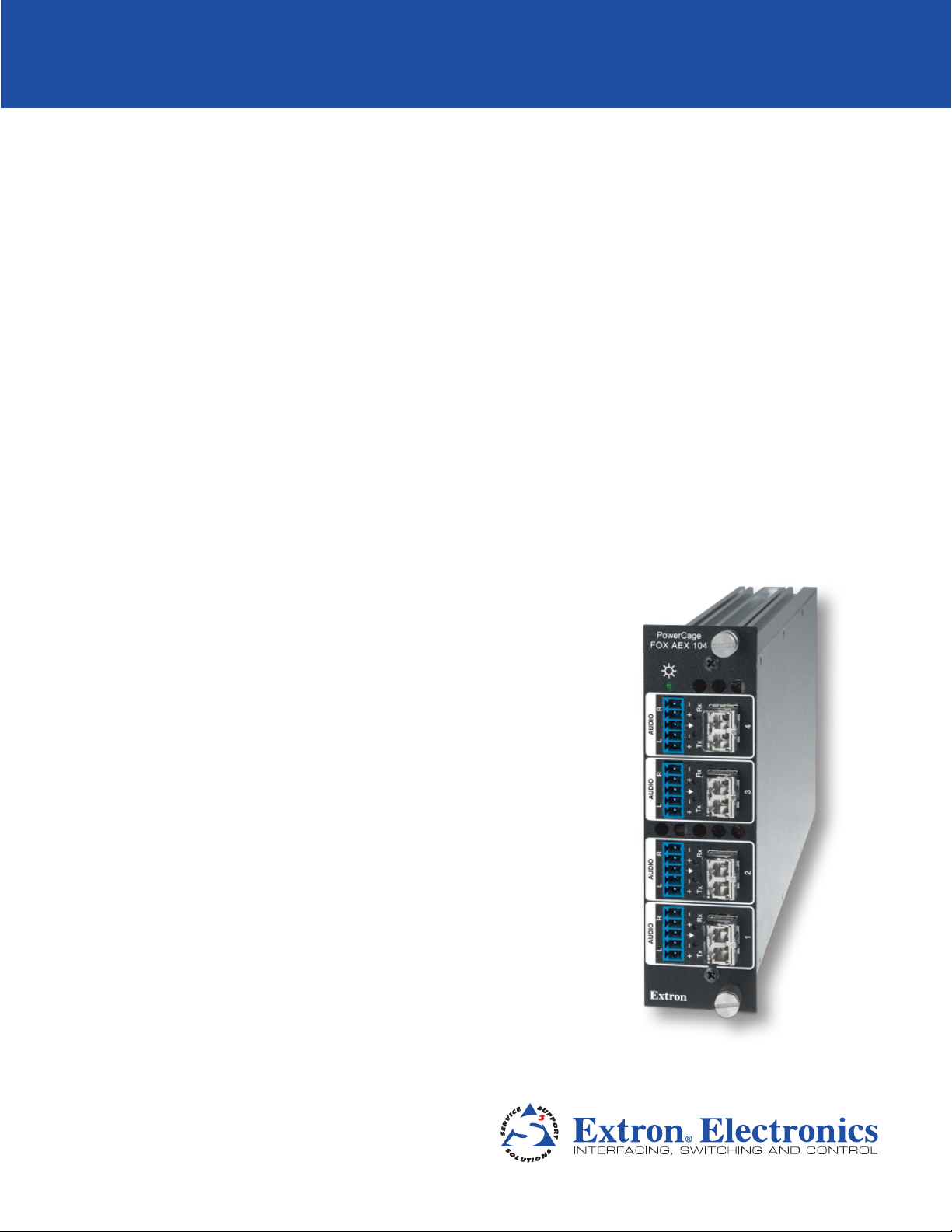
Fiber Optic Audio Extractor
PowerCage
Four Input Fiber Optic Audio Extractor
™
FOX AEX 104
68-2064-01 Rev. A
04 12
Page 2
Safety Instructions • English
This symbol is intended to alert the user of important operating and maintenance (servicing) instructions in the literature provided with the equipment.
This symbol is intended to alert the user of the presence of uninsulated
dangerous voltage within the product’s enclosure that may present a risk of
electric shock.
Caution
Read Instructions • Read and understand all safety and operating instructions before using the equipment.
Retain Instructions • The safety instructions should be kept for future reference.
Follow Warnings • Follow all warnings and instructions marked on the equipment or in the user information.
Avoid Attachments • Do not use tools or attachments that are not recommended by the equipment
manufacturer because they may be hazardous.
Warning
Power sources • This equipment should be operated only from the power source indicated on the product. This
equipment is intended to be used with a main power system with a grounded (neutral) conductor. The third
(grounding) pin is a safety feature, do not attempt to bypass or disable it.
Power disconnection • To remove power from the equipment safely, remove all power cords from the rear of
the equipment, or the desktop power module (if detachable), or from the power source receptacle (wall plug).
Power cord protection • Power cords should be routed so that they are not likely to be stepped on or pinched
by items placed upon or against them.
Servicing • Refer all servicing to qualified service personnel. There are no user-serviceable parts inside. To prevent
the risk of shock, do not attempt to service this equipment yourself because opening or removing covers may
expose you to dangerous voltage or other hazards.
Slots and openings • If the equipment has slots or holes in the enclosure, these are provided to prevent
overheating of sensitive components inside. These openings must never be blocked by other objects.
Lithium battery • There is a danger of explosion if battery is incorrectly replaced. Replace it only with the
same or equivalent type recommended by the manufacturer. Dispose of used batteries according to the
manufacturer’s instructions.
Consignes de Sécurité • Français
Ce symbole sert à avertir l’utilisateur que la documentation fournie avec le
matériel contient des instructions importantes concernant l’exploitation et la
maintenance (réparation).
Ce symbole sert à avertir l’utilisateur de la présence dans le boîtier
de l’appareil de tensions dangereuses non isolées posant des risques
d’électrocution.
Attention
Lire les instructions• Prendre connaissance de toutes les consignes de sécurité et d’exploitation avant
d’utiliser le matériel.
Conserver les instructions• Ranger les consignes de sécurité afin de pouvoir les consulter à l’avenir.
Respecter les avertissements • Observer tous les avertissements et consignes marqués sur le matériel ou
présentés dans la documentation utilisateur.
Eviter les pièces de fixation • Ne pas utiliser de pièces de fixation ni d’outils non recommandés par le
fabricant du matériel car cela risquerait de poser certains dangers.
Sicherheitsanleitungen • Deutsch
Dieses Symbol soll dem Benutzer in der im Lieferumfang enthaltenen
Dokumentation besonders wichtige Hinweise zur Bedienung und Wartung
(Instandhaltung) geben.
Dieses Symbol soll den Benutzer darauf aufmerksam machen, daß im Inneren
des Gehäuses dieses Produktes gefährliche Spannungen, die nicht isoliert sind
und die einen elektrischen Schock verursachen können, herrschen.
Achtung
Lesen der Anleitungen • Bevor Sie das Gerät zum ersten Mal verwenden, sollten Sie alle Sicherheits-und
Bedienungsanleitungen genau durchlesen und verstehen.
Aufbewahren der Anleitungen • Die Hinweise zur elektrischen Sicherheit des Produktes sollten Sie
aufbewahren, damit Sie im Bedarfsfall darauf zurückgreifen können.
Befolgen der Warnhinweise • Befolgen Sie alle Warnhinweise und Anleitungen auf dem Gerät oder in der
Benutzerdokumentation.
Keine Zusatzgeräte • Verwenden Sie keine Werkzeuge oder Zusatzgeräte, die nicht ausdrücklich vom
Hersteller empfohlen wurden, da diese eine Gefahrenquelle darstellen können.
Avertissement
Alimentations • Ne faire fonctionner ce matériel qu’avec la source d’alimentation indiquée sur l’appareil. Ce
matériel doit être utilisé avec une alimentation principale comportant un fil de terre (neutre). Le troisième
contact (de mise à la terre) constitue un dispositif de sécurité : n’essayez pas de la contourner ni de la
désactiver.
Déconnexion de l’alimentation• Pour mettre le matériel hors tension sans danger, déconnectez tous les
cordons d’alimentation de l’arrière de l’appareil ou du module d’alimentation de bureau (s’il est amovible) ou
encore de la prise secteur.
Protection du cordon d’alimentation • Acheminer les cordons d’alimentation de manière à ce que personne
ne risque de marcher dessus et à ce qu’ils ne soient pas écrasés ou pincés par des objets.
Réparation-maintenance • Faire exécuter toutes les interventions de réparation-maintenance par un
technicien qualifié. Aucun des éléments internes ne peut être réparé par l’utilisateur. Afin d’éviter tout danger
d’électrocution, l’utilisateur ne doit pas essayer de procéder lui-même à ces opérations car l’ouverture ou le
retrait des couvercles risquent de l’exposer à de hautes tensions et autres dangers.
Fentes et orifices • Si le boîtier de l’appareil comporte des fentes ou des orifices, ceux-ci servent à empêcher les
composants internes sensibles de surchauffer. Ces ouvertures ne doivent jamais être bloquées par des objets.
Lithium Batterie • Il a danger d’explosion s’ll y a remplacment incorrect de la batterie. Remplacer uniquement
avec une batterie du meme type ou d’un ype equivalent recommande par le constructeur. Mettre au reut les
batteries usagees conformement aux instructions du fabricant.
Vorsicht
Stromquellen • Dieses Gerät sollte nur über die auf dem Produkt angegebene Stromquelle betrieben werden.
Dieses Gerät wurde für eine Verwendung mit einer Hauptstromleitung mit einem geerdeten (neutralen) Leiter
konzipiert. Der dritte Kontakt ist für einen Erdanschluß, und stellt eine Sicherheitsfunktion dar. Diese sollte nicht
umgangen oder außer Betrieb gesetzt werden.
Stromunterbrechung • Um das Gerät auf sichere Weise vom Netz zu trennen, sollten Sie alle Netzkabel aus der
Rückseite des Gerätes, aus der externen Stomversorgung (falls dies möglich ist) oder aus der Wandsteckdose
ziehen.
Schutz des Netzkabels • Netzkabel sollten stets so verlegt werden, daß sie nicht im Weg liegen und niemand
darauf treten kann oder Objekte darauf- oder unmittelbar dagegengestellt werden können.
Wartung • Alle Wartungsmaßnahmen sollten nur von qualiziertem Servicepersonal durchgeführt werden.
Die internen Komponenten des Gerätes sind wartungsfrei. Zur Vermeidung eines elektrischen Schocks
versuchen Sie in keinem Fall, dieses Gerät selbst öffnen, da beim Entfernen der Abdeckungen die Gefahr eines
elektrischen Schlags und/oder andere Gefahren bestehen.
Schlitze und Öffnungen • Wenn das Gerät Schlitze oder Löcher im Gehäuse aufweist, dienen diese zur
Vermeidung einer Überhitzung der empndlichen Teile im Inneren. Diese Öffnungen dürfen niemals von
anderen Objekten blockiert werden.
Litium-Batterie • Explosionsgefahr, falls die Batterie nicht richtig ersetzt wird. Ersetzen Sie verbrauchte Batterien
nur durch den gleichen oder einen vergleichbaren Batterietyp, der auch vom Hersteller empfohlen wird.
Entsorgen Sie verbrauchte Batterien bitte gemäß den Herstelleranweisungen.
Instrucciones de seguridad • Español
Este símbolo se utiliza para advertir al usuario sobre instrucciones importantes de operación y mantenimiento (o cambio de partes) que se desean
destacar en el contenido de la documentación suministrada con los equipos.
Este símbolo se utiliza para advertir al usuario sobre la presencia de elementos con voltaje peligroso sin protección aislante, que puedan encontrarse
dentro de la caja o alojamiento del producto, y que puedan representar
riesgo de electrocución.
Precaucion
Leer las instrucciones • Leer y analizar todas las instrucciones de operación y seguridad, antes de usar el
equipo.
Conservar las instrucciones • Conservar las instrucciones de seguridad para futura consulta.
Obedecer las advertencias • Todas las advertencias e instrucciones marcadas en el equipo o en la
documentación del usuario, deben ser obedecidas.
Evitar el uso de accesorios • No usar herramientas o accesorios que no sean especificamente
recomendados por el fabricante, ya que podrian implicar riesgos.
安全须知 • 中文
这个符号提示用户该设备用户手册中有重要的操作 和维护 说明。
这个符号警告用户该设备机壳内有暴露的危险电压,有触电危险。
注意
阅读说明书 • 用户使用该设备前必须阅读并理解所有安全和使用说明。
保存说明书 • 用 户应保存安全说明书以备将来使用。
遵守警告 • 用户应遵守产品和用户指 南上的所有安 全和操 作说明。
避免追加 • 不要使用该产品厂商没有推荐的工具或追加设备,以避免危险。
Advertencia
Alimentación eléctrica • Este equipo debe conectarse únicamente a la fuente/tipo de alimentación eléctrica
indicada en el mismo. La alimentación eléctrica de este equipo debe provenir de un sistema de distribución
general con conductor neutro a tierra. La tercera pata (puesta a tierra) es una medida de seguridad, no
puentearia ni eliminaria.
Desconexión de alimentación eléctrica • Para desconectar con seguridad la acometida de alimentación
eléctrica al equipo, desenchufar todos los cables de alimentación en el panel trasero del equipo, o desenchufar
el módulo de alimentación (si fuera independiente), o desenchufar el cable del receptáculo de la pared.
Protección del cables de alimentación • Los cables de alimentación eléctrica se deben instalar en lugares
donde no sean pisados ni apretados por objetos que se puedan apoyar sobre ellos.
Reparaciones/mantenimiento • Solicitar siempre los servicios técnicos de personal calicado. En el interior no
hay partes a las que el usuario deba acceder. Para evitar riesgo de electrocución, no intentar personalmente la
reparación/mantenimiento de este equipo, ya que al abrir o extraer las tapas puede quedar expuesto a voltajes
peligrosos u otros riesgos.
Ranuras y aberturas • Si el equipo posee ranuras o orificios en su caja/alojamiento, es para evitar el
sobrecalientamiento de componentes internos sensibles. Estas aberturas nunca se deben obstruir con otros
objetos.
Batería de litio • Existe riesgo de explosión si esta batería se coloca en la posición incorrecta. Cambiar esta
batería únicamente con el mismo tipo (o su equivalente) recomendado por el fabricante. Desachar las baterías
usadas siguiendo las instrucciones del fabricante.
警告
电源 • 该设备只能使用产品上标明的电源。 设备必须使用有地线的供电系统供电。 第三条线(
地线)是安全设施,不能不用或跳过 。
拔掉电源 • 为安全地从设备拔掉电源,请拔掉所有设备后或桌面电源的电源线,或任何接到市电
系统的电源 线。
电源线保护 • 妥善布线, 避免被踩踏,或重物挤压。
维护 • 所有维修必须由认证的维修人员进行。 设备内部没有用户可以更换的零件。为避免出现触
电危险不要自己试图打开设备盖子维修该设备。
通风孔 • 有些设备机壳 上有通风槽或孔,它们是用来防止机内敏感元件过热。 不要用任何东西
挡住通风孔。
锂电池 • 不正确的更换电池会有爆炸的危 险。必须使用与厂家推荐的相同或相近型号的电池。按
照生产厂 的建议处 理废 弃电池。
Page 3

FCC Class A Notice
This equipment has been tested and found to comply with the limits for a Class A digital device, pursuant to part 15
of the FCC Rules. Operation is subject to the following two conditions:
1. This device may not cause harmful interference.
2. This device must accept any interference received, including interference that may cause undesired operation.
The Class A limits are designed to provide reasonable protection against harmful interference when the equipment
is operated in a commercial environment. This equipment generates, uses, and can radiate radio frequency energy
and, if not installed and used in accordance with the instruction manual, may cause harmful interference to radio
communications. Operation of this equipment in a residential area is likely to cause harmful interference, in which
case the user will be required to correct the interference at his own expense.
NOTE: This unit was tested with shielded cables on the peripheral devices. Shielded cables must be used with
the unit to ensure compliance with FCC emissions limits.
For more information on safety guidelines, regulatory compliances, EMI/EMF compliance, accessibility, and
related topics, click here.
Page 4
Conventions Used in this Guide
Notifications
In this user guide, the following are used:
CAUTION: A caution indicates a potential hazard to equipment or data.
NOTE: A note draws attention to important information.
TIP: A tip provides a suggestion to make working with the application easier.
WARNING: A warning warns of things or actions that might cause injury, death, or
other severe consequences.
Ground Symbols
NOTE: Control signal ground pins may be labeled as or “G.” Audio ground pins may
be labeled as or .
The wiring and function are the same, whichever way your product is labeled.
Copyright
© 2012 Extron Electronics. All rights reserved.
Trademarks
All trademarks mentioned in this guide are the properties of their respective owners.
Page 5

Contents
Introduction............................................................ 1
About This Guide ................................................ 1
About the PowerCage FOX AEX 104 ................... 1
Features .............................................................. 2
Application Diagrams .......................................... 3
Point-to-point Application ............................... 3
Before a Fiber Matrix Application .................... 4
After a Fiber Matrix Application ...................... 5
Installation and Operation.................................. 6
Mounting the Units............................................. 6
Rear Panel Features ............................................. 6
Wiring the Audio Connectors .......................... 7
System Operation ............................................... 7
Wiring Congurations ..................................... 7
Changing the Input Data Rate ......................... 8
Reference Information ......................................... 9
Specifications ...................................................... 9
Part Numbers .................................................... 11
PowerCage FOX AEX 104 Boards .................. 11
Included Parts ............................................... 11
Optional Accessories ..................................... 11
Installing a Board in the Enclosure ..................... 12
Extron Warranty .................................................. 13
vPowerCage FOX AEX 104 • Contents
Page 6

PowerCage FOX AEX 104 • Contents vi
Page 7

Introduction
This section provides general descriptions of the this guide and the PowerCage FOX AEX
104. Topics in this section include:
• About This Guide
• About the PowerCage FOX AEX 104
• Features
• Application Diagrams
About This Guide
This guide provides installation, configuration, and operation information about the two
models of the PowerCage FOX AEX 104 fiber optic audio extractors. The PowerCage
FOX AEX 104 is available in two transmission modes:
• PowerCage FOX AEX 104 SM — 4-input singlemode audio extractor, containing
1310 nm SFP modules.
• PowerCage FOX AEX 104 MM — 4-input multimode audio extractor, containing
850 nm SFP modules.
In this guide, the term “PowerCage FOX AEX 104” refers to either
PowerCage FOX AEX 104 singlemode or PowerCage FOX AEX 104 multimode models.
NOTE: A color-coded sticker on the rear panel identifies the type: orange for
multimode and yellow for singlemode.
About the PowerCage FOX AEX 104
The PowerCage FOX AEX 104 is a four input fiber audio extraction product that extracts
local audio in a fiber matrix application. It is a board to be installed in an Extron PowerCage
enclosure.
NOTES: • The multimode and singlemode PowerCage FOX AEX 104 audio extractors are
physically and functionally identical with the exception of the effective range
of transmission.
• The FOX audio extractor is compatible with all FOX products with the
exception of the FOX 3G HD-SDI transmitter and receiver products.
• The PowerCage FOX AEX 104 MM and the PowerCage FOX AEX 104 SM are
not compatible with each other.
1PowerCage FOX AEX 104 • Introduction
Page 8

Features
Local audio outputs — Local audio outputs for up to four FOX Series fiber optic signals,
extracting analog stereo audio for independent processing and routing
Inputs — Four fiber optic LC connectors with buffered Loop-throughs
Outputs — Four 5-pole captive screw connectors for balanced or unbalanced analog stereo
audio.
Simultaneous audio extraction ports — Each port accepts signals from a FOX Series fiber
optic product to provide local analog stereo audio output, and retransmits the fiber optic
signal at the original power level.
Buffered input loop-throughs — Full transmitter power on each output maximizes
distance capabilities by ensuring full availability of optical loss budget.
Balanced or unbalanced analog audio outputs — Provide balanced or unbalanced
stereo audio on captive screw output connectors for integration with audio processing and
distribution equipment.
Output reclocking — Reshapes and restores timing of the digital signal.
Multimode and singlemode availability — Available as an 850 nm multimode model
for moderate-range transmissions and a 1310 nm singlemode model for extreme distances
up to 30 km (18.75 miles). A PowerCage FOX AEX 104, connected between a FOX Series
transmitter and receiver, effectively doubles the overall transmission distance capability. For
singlemode applications, signals can be sent up to 60 km (37.5 miles) from a transmitter to a
receiver via the PowerCage FOX AEX 104.
Reliable physical connectivity — Industry standard LC connectors provide reliable physical
connectivity and precise fiber core alignment.
Compatibility with the following Extron FOX Series:
• Matrix switchers — Provides a convenient location for audio extraction in a matrix
switching environment for signal distribution systems up to 1000x1000 and larger. Each
port includes an input with a loop-through, enabling in-line installation without using
valuable dedicated switching resources or a matrix switcher slot.
• Distribution amplifiers —Supports virtually any fiber optic switching and distribution
environment for maximum design flexibility.
• HDMI, DVI Plus, DVI, VGA, VGA/YUV, and AV transmitters and receivers —
Provides audio extraction for a wide variety of sources and displays.
NOTES: • The PowerCage FOX AEX 104 is not compatible with the FOX 3G HD-SDI
extender or the FOX 3G DVC signal converter.
• Transmission of HDMI video with HDCP content requires two fibers.
Internal universal power supply — The 100-240 VAC, 50 or 60 Hz, international power
supply provides worldwide power compatibility.
Audio Output — The extractor outputs balanced or unbalanced stereo audio on a 3.5 mm,
5-pole captive screw connector.
Input Data Rate Selection — A recessed toggle switch on the front panel allows for
selectable input data rates. The PowerCage FOX AEX 104 can be set to 2G or 4G rates.
Power — 120 V or 240 VAC, 50 or 60 Hz power source
PowerCage Mounting — All PowerCage FOX AEX 104 units are mountable in any Extron
PowerCage enclosure.
PowerCage FOX AEX 104 • Introduction 2
Page 9

Application Diagrams
The PowerCage FOX AEX 104 can be used anywhere local audio-only outputs are required:
before a FOX matrix switcher for independent processing of source audio signals by a DSP
processor or after a FOX matrix switcher for routing to audio amplifiers or a DSP processor.
Each audio extraction point works independently. The following are examples of typical
integrations of the PowerCage FOX AEX 104 in fiber optic systems.
NOTES: • The extraction points in all three applications work independently.
Point-to-point Application
In systems without a fiber matrix switcher, the PowerCage FOX AEX 104 can be incorporated
between the fiber transceiver and the fiber receiver (see figure 1).
• Transmission of HDMI video with HDCP content requires two fibers.
Local 2-ch Audio Out
PowerCage
FOX AEX 104
4
Rx
PowerCage
RL
FOX AEX 104
Tx
AUDIO
4
3
Rx
Rx
PowerCage
RL
FOX AEX 104
RL
Tx
Tx
AUDIO
4
AUDIO
3
Rx
Rx
PowerCage
RL
FOX AEX 104
AUDIO
4
Rx
PowerCage
FOX AEX 104
RL
RL
Tx
AUDIO
4
AUDIO
3
Rx
PowerCage
Rx
FOX AEX 104
RL
RL
Tx
Tx
AUDIO
4
RL
AUDIO
3
Rx
Rx
PowerCage
RL
FOX AEX 104
AUDIO
4
Rx
PowerCage
RL
FOX AEX 104
RL
Tx
AUDIO
4
AUDIO
3
Rx
Rx
RL
RL
Tx
Tx
AUDIO
RL
AUDIO
3
Rx
AUDIO
2
RL
Rx
Tx
RL
AUDIO
RL
Tx
AUDIO
2
AUDIO
1
Rx
Rx
RL
RL
Tx
Tx
AUDIO
Extron
AUDIO
1
Rx
RL
Tx
Extron
AUDIO
100-240V 50/60Hz
5A MAX.
Extron
RL
Tx
Tx
RL
AUDIO
3
Rx
AUDIO
2
Rx
Tx
RL
RL
Tx
AUDIO
2
AUDIO
1
Rx
Rx
RL
Tx
Tx
Extron
AUDIO
1
Rx
Tx
Extron
AUDIO
2
Rx
RL
Tx
AUDIO
1
Rx
Tx
Extron
Extron
FOX AEX 104
Four Port Fiber
Optic Audio
Extractor
2
RL
Rx
Tx
Tx
RL
AUDIO
3
Tx
Rx
AUDIO
2
1
Rx
Rx
Tx
RL
RL
Tx
Tx
AUDIO
2
AUDIO
1
Rx
Rx
RL
Tx
Tx
Extron
AUDIO
1
Rx
Tx
Extron
R
AUDIO
L
OUTPUTS
Tx Rx 1 2
HDMI
HDMI AUDIO
Extron
FOXBOX Rx HDMI
Fiber Optic Receiver
Flat Panel Display
ON
OFF
Rx
FOX SR HDMI
Tx
LINK
LINK
POWER
OPTICAL
12V
1.0A MAX
Blu-ray Player
Rx
LINK
Tx
LINK
ALARM
OPTICAL
RS-232
OVER FIBER
FOXBOX Tx HDMI
Tx Rx 1 2
POWER
AUDIO INPUT
12V
1.0A MAX
HDMI
Extron
FOXBOX Tx HDMI
Fiber Optic Transmitte r
Figure 1. Typical Point-to-point PowerCage FOX AEX 104 Application Diagram
PowerCage FOX AEX 104 • Introduction 3
Page 10

Before a Fiber Matrix Application
The PowerCage FOX AEX 104 can be placed before a fiber matrix switcher for independent
processing of source audio signals by a DSP processor (see figure 2).
OUT
1 - 8
ANAHEIM, CA
OUT
9 - 16
OUT
17 - 24
OUT
25 - 32
100-240V 50/60Hz 1.2A MAX.
RESET
REMOTE
RS-232/RS-422
BI-LEVEL
DISCONNECT BOTH POWER
LAN
CORDS BEFORE SERVICING
TRI-LEVEL
ACT LINK
SWITCH
100-240V 50/60Hz 1.2A MAX.
REFERENCE
STANDBY/ON
Blu-ray Player
PQLS HDMI OPEN/CLOSE FL OFF
USB
POWER
12V
1.0A MAX
Extron
FOXBOX Tx HDMI
Fiber Optic Transmitte r
RxTx
FOXBOX Tx HDMI
RS-232
OVER FIBER
ALARM
LINK
LINK
Tx Rx 1 2
OPTICAL
AUDIO INPUT
HDMI
OUT
OUT
IN
C
OUT
IN
C
OUT
IN
C
OUT
IN
C
PRIMARY POWER SUPPLY
IN
D
OUT
IN
D
OUT
IN
D
OUT
IN
D
OUT
IN
OUT
IN
B
A
OUT
IN
OUT
IN
B
A
OUT
IN
OUT
IN
B
A
OUT
IN
OUT
IN
B
A
REDUNDANT
PRIMARY
Extron
FOX Matrix 3200
Modular Fiber Optic Matrix Switcher
Local 2-ch Audio Out
PowerCage
PowerCage 1600
100-240V 50/60Hz
PowerCage 1600
C US
N15778
LISTED
1T23
L.T.E.
5A MAX.
FOX AEX 104
Power Supply
Power Supply
RL
Rx
4
AUDIO
Tx
RL
Rx
3
AUDIO
Tx
RL
Rx
2
AUDIO
Tx
RL
Rx
1
AUDIO
Tx
Extron
Extron
FOX AEX 104
FOX Series Audio
Extractor
OUT
IN
OUTINOUT
E
F
OUT
IN
OUTINOUT
E
F
OUT
IN
OUTINOUT
E
F
OUT
IN
OUTINOUT
E
F
REDUNDANT POWER SUPPLY
PowerCage
PowerCage
FOX AEX 104
AUDIO
AUDIO
AUDIO
AUDIO
Extron
PowerCage
FOX AEX 104
FOX AEX 104
RL
RL
Rx
Rx
4
4
AUDIO
AUDIO
Tx
Tx
RL
RL
Rx
Rx
3
3
AUDIO
AUDIO
Tx
Tx
RL
RL
Rx
Rx
2
2
AUDIO
AUDIO
Tx
Tx
RL
RL
Rx
Rx
1
1
AUDIO
AUDIO
Tx
Tx
Extron
Extron
Extron
PowerCage 1600
IN
OUT
IN
G
H
IN
OUT
IN
G
H
IN
OUT
IN
G
H
IN
OUT
IN
G
H
PowerCage
PowerCage
PowerCage
PowerCage
FOX AEX 104
FOX AEX 104
RL
RL
Rx
Rx
4
4
AUDIO
Tx
Tx
RL
RL
Rx
Rx
3
3
AUDIO
Tx
Tx
RL
RL
Rx
Rx
2
2
AUDIO
Tx
Tx
RL
RL
Rx
Rx
1
1
AUDIO
Tx
Tx
Extron
Extron
FOX AEX 104
FOX AEX 104
RL
RL
RL
Rx
AUDIO
Tx
RL
Rx
AUDIO
Tx
RL
Rx
AUDIO
Tx
RL
Rx
AUDIO
Tx
Rx
Rx
4
4
4
AUDIO
AUDIO
Tx
Tx
RL
RL
Rx
Rx
3
3
3
AUDIO
AUDIO
Tx
Tx
RL
RL
Rx
Rx
2
2
2
AUDIO
AUDIO
Tx
Tx
RL
RL
Rx
Rx
1
1
1
AUDIO
AUDIO
Tx
Tx
Extron
Extron
Display
FOXBOX Rx HDMI
OUTPUTS
HDMI AUDIO
AUDIO
REMOTE
RS-232
RS-232
ALARM
OVER FIBER
LR
ON
OFF
Tx Rx 1 2
HDMI
Tx Rx
RxTx
POWER
12V
1.0 A MAX
LINK
LINK
OPTICAL
Extron
FOXBOX Rx HDMI
Fiber Optic Receiver
Figure 2. Typical PowerCage FOX AEX 104 before a Fiber Matrix Application
Diagram
PowerCage FOX AEX 104 • Introduction 4
Page 11

After a Fiber Matrix Application
The PowerCage FOX AEX 104 can also be placed after a FOX matrix switcher for routing to
audio amplifiers or a DSP processor (see figure 3).
Extron
PowerCage FOX AEX 104
FOX Series Audio Extractor
PowerCage
FOX AEX 104
RL
AUDIO
RL
AUDIO
RL
AUDIO
RL
AUDIO
Rx
4
Tx
Rx
3
Tx
Rx
2
Tx
Rx
1
Tx
Extron
XPA 1002
Power Amplier
Extron
Extron
PowerCage 1600
N15778
100-240V 50/60Hz
5A MAX.
Extron
FOXBOX Tx HDMI
Fiber Optic Transmitter
STANDBY/ON
PQLS HDMI OPEN/CLOSE FL OFF
Blu-ray Player
Extron
FOXBOX Tx DVI Plus
Fiber Optic Transmitter
Laptop
Extron
FOXBOX Tx VGA/YUV
Fiber Optic Transmitter
PowerCage 1600
PowerCage 1600
Power Supply
Power Supply
C US
LISTED
1T23
L.T.E.
HDMI LOOP THRU
50Hz
DIGITAL
EDID MINDER
AUDIO
HDCP
HDMI
CONFIG
AUDIO
1
2
ANALOG60Hz
POWER
12V
1.0A MAX
USB
POWER
12V
1.0A MAX
POWER
12V
1.0A MAX
FOXBOX Tx HDMI
RxTx
FOXBOX Tx HDMI
RS-232
OVER FIBER
ALARM
LINK
LINK
Tx Rx 1 2
OPTICAL
AUDIO INPUT
HDMI
Rx
Tx
DVI
OVER
TEMP
AUDIO
LINK
LINK
CONFIG
FOXBOX Tx DVI Plus
OPTICAL
RS-232
DVI-D INPUT
AUDIO
ALARM
OVER FIBER
Tx Rx 1 2
FOXBOX Tx DVI Plus
Rx
Tx
RGB/
YUV
OVER
TEMP
AUDIO
LINK
LINK
CONFIG
FOXBOX Tx VGA/YUV
OPTICAL
RGB/YUV INPUT
RS-232
AUDIO
ALARM
OVER FIBER
Tx Rx 1 2
FOXBOX Tx VGA/YUV
PowerCage
FOX AEX 104
RL
Rx
4
AUDIO
Tx
RL
Rx
3
AUDIO
Tx
RL
Rx
2
AUDIO
Tx
RL
Rx
1
AUDIO
Tx
Extron
OUT
OUT
IN
1 - 8
A
ANAHEIM, CA
OUT
OUT
IN
9 - 16
A
OUT
OUT
IN
17 - 24
A
OUT
OUT
IN
25 - 32
A
100-240V 50/60Hz 1.2A MAX.
RESET
REFERENCE
BI-LEVEL
TRI-LEVEL
SWITCH
DISCONNECT BOTH POWER
CORDS BEFORE SERVICING
100-240V 50/60Hz 1.2A MAX.
REDUNDANT
PRIMARY
REMOTE
RS-232/RS-422
LAN
ACT LINK
Extron
FOX Matrix 3200
Modular Fiber Optic Matrix Switche r
DVD Player
100-240V 1.3A, 50-60Hz
POWER
12V
1.5A MAX
OUT
OUT
IN
IN
IN
B
IN
B
IN
B
IN
B
C
OUT
IN
C
OUT
IN
C
OUT
IN
C
PRIMARY POWER SUPPLY
D
OUT
IN
D
OUT
IN
D
OUT
IN
D
LEVEL
12
2
1
LIMITER/
PROTECT
SIGNAL
0 0
1
3
2
MIC/LINE INPUTS
O
U
T
MIC
+48V
P
6
4
OUT
OUT
OUT
OUT
U
5
3
251
T
6
4
S
OUT
IN
IN
E
F
OUT
IN
IN
E
F
OUT
IN
IN
E
F
OUT
IN
IN
E
F
REDUNDANT POWER SUPPLY
XPA 1002
2
LAN
Extron
SI 28
Surface-mount
Speakers
DMP 64
Extron
DMP 64
RESET
Digital Matrix
Processor
POWER
12V
1.0 A MAX
Extron
FOXBOX SR HDMI
Fiber Optic Scaling Receiver
POWER
12V
1.0 A MAX
Extron
FOXBOX SR HDMI
Fiber Optic Scaling Receiver
POWER
12V
1.0 A MAX LR
Extron
FOXBOX SR HDMI
Fiber Optic Scaling Receiver
Display
FOXBOX SR HDMI
OUTPUTS
HDMI AUDIO
AUDIO
REMOTE
RS-232
RS-232
ALARM
OVER FIBER
LR
ON
OFF
Tx Rx 1 2
HDMI
Tx Rx
RxTx
LINK
LINK
OPTICAL
Projector
FOXBOX SR HDMI
FOXBOX SR HDMI
OUTPUTS
HDMI AUDIO
AUDIO
REMOTE
RS-232
RS-232
ALARM
OVER FIBER
LR
ON
OFF
Tx Rx 1 2
HDMI
OUTPUTS
HDMI AUDIO
ON
OFF
HDMI
AUDIO
Display
RS-232
ALARM
OVER FIBER
Tx Rx 1 2
Tx Rx
REMOTE
RS-232
Tx Rx
RxTx
LINK
LINK
OPTICAL
RxTx
LINK
LINK
OPTICAL
CLASS 2 WIRING
OUTPUT
INPUTS
REMOTE
1
10V 50 mA
VOL/MUTE
2
1
STANDBY
1
2
RS-232(1)
I/O
TxRx
123
456
4
RS-232(2)
3
TxRx
OUT
OUT
IN
IN
H
G
OUT
OUT
IN
IN
H
G
OUT
OUT
IN
IN
H
G
OUT
OUT
IN
IN
H
G
Figure 3. Typical PowerCage FOX AEX 104 after a Fiber Matrix Application
Diagram
PowerCage FOX AEX 104 • Introduction 5
Page 12

Installation and
AUDIO
RL
+-
-+
Operation
This section describes how to integrate the PowerCage FOX AEX 104 into a FOX matrix
system and how to operate it. Topics in this section include:
• Mounting the Units
• Rear Panel Features
• System Operation
Mounting the Units
The PowerCage FOX AEX 104 must be installed in a PowerCage 1600 enclosure (see
Installing a Board in the Enclosure on page 12).
Rear Panel Features
b
Extron
AUDIOAUDIO AUDIO
RL
Tx
1
Ä
Rx
Å
Tx
Ä Å
AUDIO
2
c
RL
Rx
AUDIO
RL
Tx
3
Ä Å
Rx
Tx
Ä Å
AUDIO
4
d
FOX AEX 104
RL
Rx
PowerCage
Figure 4. PowerCage FOX AEX 104 Rear Panel
Fiber optic connector — One dual port LC SFP module for fiber Tx or Rx transmission
a
with two LEDs for fiber link status. There is one for each of the four extraction points.
WARNING: These units output continuous invisible light, which may be harmful
to the eyes; use with caution. For additional safety, plug the attached
dust caps into the optical transceivers when the fiber cable is
unplugged.
NOTE: Each fiber input has a re-clocker circuitry to maintain signal integrity.
Tx connector — Connect a fiber optic cable to the Tx LC connector.
Ä
Rx connector — For all one-way video, audio, and serial communications
Å
from the transmitter to the receiver, connect a fiber optic cable to the
Rx LC connector.
Rx
Tx
6PowerCage FOX AEX 104 • Installation and Operation
Page 13

Slee
AUDIO
+-
-+
RxTx
b
c
Power LED indicator — Lights when power is applied.
d
Wiring the Audio Connectors
Connect a 3.5 mm, 5-pole captive screw audio connectors for stereo audio output. This
output is unamplified line level audio. Wire the connector as show in figure 5.
Tip
Ring
ves
Tip
Ring
Figure 5. Captive Screw Connector Wiring for Audio Signals
System Operation
Wiring Configurations
The PowerCage FOX AEX 104 can be used anywhere local audio-only outputs are required.
The following instructions describe integrating the PowerCage FOX AEX 104 after a
FOX matrix switcher for routing to an audio amplifier or a DSP processor. It can also be
incorporated before a FOX matrix switcher for independent processing of source audio
signals by a DSP processor (see Application Diagrams on page 3 for other potential
applications). Each audio extraction point works independently.
Tx and Rx indicator LEDs — The optical Tx and Rx LED lightsi indicate fiber
light presence. The Rx LED lights when the Rx device receives light from fiber 1.
The Tx LED lights as soon as there is light presence on the Rx LED.
Audio connector — Connect a 3.5 mm, 5-pole captive screw audio
connector for each extraction point.
Balanced Audio Output
LR
Sleeves
No Ground Here
Tip
Tip
No Ground Here
Unbalanced Audio Output
LR
Do not tin the wires!
RL
NOTE: Transmission of HDMI video with HDCP content requires two fibers.
1. Connect the fiber output (OUT) of the matrix switcher to the Rx port of an extraction
point on the PowerCage FOX AEX 104.
2. Connect the Tx port of the same extraction point to the FOX receiver (Rx).
3. Connect the Tx port of the FOX receiver back into the receiver port on the matrix
switcher (Rx).
4. Connect local 2-ch audio output to the Audio connector of the extraction point.
After the PowerCage FOX AEX 104 and all connected devices are powered up, the system is
fully operational. If any problems are encountered, ensure all traditional and fiber cables are
routed and connected properly.
TIP: If problems persist, call the Extron S3 Sales and Technical Support Hotline (see the
Contact Information on the last page for contact numbers).
PowerCage FOX AEX 104 • Installation and Operation 7
Page 14

Changing the Input Data Rate
O
N
12
The DIP switch on the main board switches the PowerCage FOX AEX 104 between 2G and
4G input data rates.
1. If necessary, remove the PowerCage FOX AEX 104 board from the PowerCage
enclosure.
2. Use an Extron Tweeker to move DIP switch 2 up (On position) for 2G input data
rates or down (Off position) for 4G input data rates.
3. Reinstall the PowerCage FOX AEX 104 board into the PowerCage enclosure to cycle
power back to the board (see Installing a Board in the Enclosure on page 12).
DIP switch 1 is a spare. The default rate is 4G (Off or down).
NOTE: Selectable rates apply to all extraction points. They are not for individual inputs.
CAUTION: Ensure all fiber extenders within the system are compatible with the selected
input data rate.
PowerCage FOX AEX 104 • Installation and Operation 8
Page 15

Reference Information
This section provides supplementary information about the PowerCage FOX AEX 104 and
related products. Topics in this section include:
• Specifications
• Part Numbers
• Installing a Board in the Enclosure
Specifications
NOTES: • Analog audio signals are digitized in a fiber optic transmitter, sent through the fiber calbe to the matrix
switcher, then the PowerCage FOX AEX 104, and converted back to analog audio in the PowerCage
FOX AEX 104 or the receiver.
• These units are class 1 laser products. They meet the safety regulations of IEC-60825,
FDA 21 CFR 1040.10, and FDA 21 CFR 1040.11.
• The PowerCage FOX AEX 104 is not compatible with the FOX 3G HD-SDI extender or the FOX 3G DVC
signal converter.
Optical fiber interconnection between transmitter or fiber matrix and receiver
Number/type .................................. 2 fibers per extraction point
Connectors .................................... 8 LC connectors
Operating distance
Singlemode ............................. 30 km (18.75 miles) with singlemode (SM) cables with a PowerCage FOX SM unit
Multimode ............................... 300 m (985') with 62.5 µm OM1 multimode (MM) cables with a
NOTE: Operating distance is approximate. These are typical maximum distances that may vary depending on
factors such as fiber type, fiber bandwidth, connector splicing, losses, modal or chromatic dispersion,
environmental factors, and kinks.
PowerCage FOX MM unit
1 km (3280') with 50 µm OM2 multimode (MM) cables with a
PowerCage FOX MM unit
2 km (6561') with 50 µm OM3/OM4 2000 MHz bandwidth laser optimized
multimode cable with a PowerCage FOX MM unit
Nominal peak wavelength .............. 850 nm for MM units, 1310 nm for SM units
Data rate ........................................ 4.25 Gbps or 2.125 Gbps, selectable
Transmission power
Singlemode ............................. -5 dBm, typical
Multimode ............................... -5 dBm, typical
Maximum receiver sensitivity
Singlemode ............................. -18 dBm, typical
Multimode ............................... -12 dBm, typical
Optical loss budget
Singlemode ............................. 13 dB, maximum
Multimode ............................... 7 dB, maximum
Audio
Gain
Default .................................... Unbalanced output: –6 dB
Balanced output: 0 dB
9PowerCage FOX AEX 104 • Reference Information
Page 16

Frequency response ........................ 20 Hz to 20 kHz, ±0.5 dB
THD + Noise ................................... 0.10% @ 1 kHz at nominal level
S/N ................................................. >80 dB at maximum output (unweighted)
Audio bits per sample ..................... 18 bits per channel, 2 channels (L, R)
Sampling rate ................................. 48 kHz
Audio input — See the transmitter specifications
Audio output
Number/signal type ........................ 4 balanced/unbalanced stereo or 8 balanced/unbalanced mono
Connectors .................................... (4) 3.5 mm captive screw connectors, 5 pole
Impedance ..................................... 50 ohms unbalanced, 100 ohms balanced
Nominal level ................................. +4 dBu (1.23 Vrms), -10 dBV (316 mVrms)
Maximum level ............................... >+11 dBu, balanced at 1% THD+N
Audio Delay ................................... 1.5 frames
NOTE: 0 dBu = 0.775 Vrms, 0 dBV = 1 Vrms, 0 dBV ≈ 2 dBu
General
Power ............................................ Supplied by a PowerCage 1600 System Enclosure
Power consumption
System ..................................... Enclosure without boards: 12.4 watts
PowerCage FOX AEX board
Power input requirement
for boards ...................................... 12 VDC, 1.0 A, supplied by the PowerCage enclosure
Temperature/humidity
Cooling .......................................... Enclosure: fans, front to back
Thermal dissipation ........................ 67.2 BTU/hr
Mounting
Rack mount
Furniture mount ...................... Yes, with optional under desk mounting kit
Enclosure type ................................ Metal
Enclosure dimensions
PowerCage enclosure .............. 5.25” H x 17.0” W x 12.25” D (3U high, full rack wide)
PowerCage FOX AEX board ..... Fits a double slot opening in a PowerCage enclosure
Product weight
PowerCage enclosure .............. 11.6 lbs (0.5 kg)
PowerCage FOX AEX board ..... 0.8 lbs (0.4 kg)
Shipping weight
PowerCage enclosure .............. 13 lbs (6 kg)
PowerCage FOX AEX board ..... 2 lbs (1 kg)
Vibration
Regulatory compliance
MTBF ............................................. 30,000 hours
Warranty ........................................ 3 years parts and labor
........................................ ISTA 1A in carton (International Safe Transit Association)
Safety ...................................... CE, c-UL, FDA Class 1, UL
EMI/EMC ................................. CE, C-tick, FCC Class A, ICES, VCCI
.................... Storage: -40 to +158 °F (-40 to +70 °C) / 10% to 90%, noncondensing
............................. Yes, with optional rack shelf
..... 19.7 watts
Operating: +32 to +122 °F (0 to +50 °C) / 10% to 90%, noncondensing
Boards: convection, within the PowerCage enclosure
13.3 cm H x 43.2 cm W x 31.2 cm D
(Depth excludes connectors on the optional boards. Width excludes rack ears.)
NOTES: • All nominal levels are at ±10%.
• Specifications are subject to change without notice.
8.0-033012-D1
PowerCage FOX AEX 104 • Reference Information 10
Page 17

Part Numbers
PowerCage FOX AEX 104 Boards
Included Parts
Optional Accessories
Boards Part Number
PowerCage FOX AEX 104 Multimode 70-960-01
PowerCage FOX AEX 104 Singlemode 70-960-02
Included Parts Part Number
Setup Guide 68-2064-50
3.5 mm, 5-pole captive screw audio connector
SFP Module (multimode or singlemode)
Fiber cable assemblies
MHR Mini High Resolution Cable Part Number
4LC MM LC to LC Multimode Fiber Optic Cable Assemblies 26-652-nn
2LC OM4 MM P LC to LC Laser-Optimized Multimode Fiber
Optic Cable Assemblies — Plenum
2LC SM P LC to LC Bend-Insensitive Singlemode Fiber Optic
Cable Assemblies — Plenum
26-671-nn
26-670-nn
Bulk fiber cable and termination tools
RG6 Super High Resolution Cable Part Number
OM4 MM P/2K Plenum 2 km (6,562 foot) Spool 22-225-02
SM P/2K Plenum 2 km (6,562 foot) Spool 22-223-02
Fiber Optic Termination Kit 100-656-01
QLC MM/10 Multimode, qty. 10 101-018-01
QLC SM/10 Singlemode, qty. 10 101-017-01
PowerCage FOX AEX 104 • Reference Information 11
Page 18

Installing a Board in the Enclosure
The PowerCage FOX AEX 104 is a double slot board for the PowerCage 1600 enclosure.
NOTE: The boards are hot-swappable and can be installed or removed without
disconnecting power to the PowerCage enclosure.
Use ESD precautions when installing a board to avoid damaging the board. Keep
the board in the anti-static bag until needed. Use proper grounding techniques
during installation.
1. If desired, move DIP switch 2 to
select the desired input data rate.
Down (Off position) is for 4G and up
is for 2G. The default position is 4G.
2. If necessary, remove power from the
PowerCage enclosure.
3. Position the board in the slot so
that the power and communication
ports on the front end of the board
are aligned with the matching ports
inside the board cage.
4. Carefully slide the board into the slot
and push the board firmly into place.
5. Tighten the two screws to secure the
board into place.
16 available single board slots or
8 double board slots
Power
Supply
100-240V 50/60Hz
5A MAX.
Screws
NOTE: Use a tool to fully tighten the screws after initial installation and subsequent
removal and replacement of the boards.
6. Repeat steps 3 through 5 for all boards needing installation.
NOTE: Ensure the boards are flush with the rear of the enclosure and the screws
tightened securely before applying power.
PowerCage FOX AEX 104 • Reference Information 12
Page 19

Extron Warranty
Extron Electronics warrants this product against defects in materials and workmanship for a period of three years
from the date of purchase. In the event of malfunction during the warranty period attributable directly to faulty
workmanship and/or materials, Extron Electronics will, at its option, repair or replace said products or components,
to whatever extent it shall deem necessary to restore said product to proper operating condition, provided that it is
returned within the warranty period, with proof of purchase and description of malfunction to:
USA, Canada, South America,
and Central America:
Extron Electronics
1001 East Ball Road
Anaheim, CA 92805
U.S.A.
Europe, Africa, and the Middle
East:
Extron Europe
Hanzeboulevard 10
3825 PH Amersfoort
The Netherlands
Asia:
Extron Asia
135 Joo Seng Road, #04-01
PM Industrial Bldg.
Singapore 368363
Japan:
Extron Electronics, Japan
Kyodo Building, 16 Ichibancho
Chiyoda-ku, Tokyo 102-0082
Japan
China:
Extron China
686 Ronghua Road
Songjiang District
Shanghai 201611
China
Middle East:
Extron Middle East
Dubai Airport Free Zone
F12, PO Box 293666
United Arab Emirates, Dubai
Singapore
This Limited Warranty does not apply if the fault has been caused by misuse, improper handling care, electrical
or mechanical abuse, abnormal operating conditions, or modifications were made to the product that were not
authorized by Extron.
NOTE: If a product is defective, please call Extron and ask for an Application Engineer to receive an RA (Return
Authorization) number. This will begin the repair process.
USA: 714.491.1500 Europe: 31.33.453.4040
Asia: 65.6383.4400 Japan: 81.3.3511.7655
Units must be returned insured, with shipping charges prepaid. If not insured, you assume the risk of loss or damage
during shipment. Returned units must include the serial number and a description of the problem, as well as the
name of the person to contact in case there are any questions.
Extron Electronics makes no further warranties either expressed or implied with respect to the product and its quality,
performance, merchantability, or tness for any particular use. In no event will Extron Electronics be liable for direct,
indirect, or consequential damages resulting from any defect in this product even if Extron Electronics has been
advised of such damage.
Please note that laws vary from state to state and country to country, and that some provisions of this warranty may
not apply to you.
Extron Headquarters
+1.800.633.9876 (Inside USA/Canada Only)
Extron USA - West Extron USA - East
+1.714.491.1500 +1.919.850.1000
+1.714.491.1517 FAX +1.919.850.1001 FAX
Extron Europe
+800.3987.6673
(Inside Europe Only)
+31.33.453.4040
+31.33.453.4050 FAX
Extron Asia
+800.7339.8766
(Inside Asia Only)
+65.6383.4400
+65.6383.4664 FAX
© 2012 Extron Electronics All rights reserved. www.extron.com
Extron Japan
+81.3.3511.7655
+81.3.3511.7656 FAX
Extron China
+4000.398766
Inside China Only
+86.21.3760.1568
+86.21.3760.1566 FAX
Extron Middle East
+971.4.2991800
+971.4.2991880 FAX
Extron Korea
+82.2.3444.1571
+82.2.3444.1575 FAX
Extron India
1800.3070.3777
Inside India Only
+91.80.3055.3777
+91.80.3055.3737 FAX
 Loading...