

Extron electronics DXP 44 HD 4K, DXP 84 HD 4K, DXP 1616 HD 4K, DXP 88 HD 4K, DXP 168 HD 4K User Manual
Page 1

DXP HD 4K Series
4K HDMI Switchers
User Guide
Matrix Switchers
68-2759-01 Rev. B
04 17
Page 2

Safety Instructions
Safety Instructions • English
WARNING: This symbol, , when used on the product, is intended to
alert the user of the presence of uninsulated dangerous voltage within
the product’s enclosure that may present a risk of electric shock.
ATTENTION: This symbol, , when used on the product, is intended
to alert the user of important operating and maintenance (servicing)
instructions in the literature provided with the equipment.
For information on safety guidelines, regulatory compliances, EMI/EMF
compatibility, accessibility, and related topics, see the Extron Safety and
Regulatory Compliance Guide, part number 68-290-01, on the Extron
website, www.extron.com.
Sicherheitsanweisungen • Deutsch
WARNUNG: Dieses Symbol auf dem Produkt soll den Benutzer
darauf aufmerksam machen, dass im Inneren des Gehäuses dieses
Produktes gefährliche Spannungen herrschen, die nicht isoliert sind und
die einen elektrischen Schlag verursachen können.
VORSICHT: Dieses Symbol auf dem Produkt soll dem Benutzer in
der im Lieferumfang enthaltenen Dokumentation besonders wichtige
Hinweise zur Bedienung und Wartung (Instandhaltung) geben.
Weitere Informationen über die Sicherheitsrichtlinien, Produkthandhabung,
EMI/EMF-Kompatibilität, Zugänglichkeit und verwandte Themen finden Sie in
den Extron-Richtlinien für Sicherheit und Handhabung (Artikelnummer
68-290-01) auf der Extron-Website, www.extron.com.
Instrucciones de seguridad • Español
ADVERTENCIA: Este símbolo, , cuando se utiliza en el producto,
avisa al usuario de la presencia de voltaje peligroso sin aislar dentro del
producto, lo que puede representar un riesgo de descarga eléctrica.
ATENCIÓN: Este símbolo, , cuando se utiliza en el producto, avisa
al usuario de la presencia de importantes instrucciones de uso y
mantenimiento recogidas en la documentación proporcionada con el
equipo.
Para obtener información sobre directrices de seguridad, cumplimiento
de normativas, compatibilidad electromagnética, accesibilidad y temas
relacionados, consulte la Guía de cumplimiento de normativas y seguridad
de Extron, referencia 68-290-01, en el sitio Web de Extron, www.extron.com.
Instructions de sécurité • Français
AVERTISSEMENT : Ce pictogramme, , lorsqu’il est utilisé sur le
produit, signale à l’utilisateur la présence à l’intérieur du boîtier du
produit d’une tension électrique dangereuse susceptible de provoquer
un choc électrique.
ATTENTION : Ce pictogramme, , lorsqu’il est utilisé sur le produit,
signale à l’utilisateur des instructions d’utilisation ou de maintenance
importantes qui se trouvent dans la documentation fournie avec le
matériel.
Pour en savoir plus sur les règles de sécurité, la conformité à la
réglementation, la compatibilité EMI/EMF, l’accessibilité, et autres sujets
connexes, lisez les informations de sécurité et de conformité Extron, réf.
68-290-01, sur le site Extron, www.extron.com.
Istruzioni di sicurezza • Italiano
AVVERTENZA: Il simbolo, , se usato sul prodotto, serve ad
avvertire l’utente della presenza di tensione non isolata pericolosa
all’interno del contenitore del prodotto che può costituire un rischio di
scosse elettriche.
ATTENTZIONE: Il simbolo, , se usato sul prodotto, serve ad
avvertire l’utente della presenza di importanti istruzioni di funzionamento
e manutenzione nella documentazione fornita con l’apparecchio.
Per informazioni su parametri di sicurezza, conformità alle normative,
compatibilità EMI/EMF, accessibilità e argomenti simili, fare riferimento
alla Guida alla conformità normativa e di sicurezza di Extron, cod. articolo
68-290-01, sul sito web di Extron, www.extron.com.
Instrukcje bezpieczeństwa • Polska
OSTRZEŻENIE: Ten symbol, , gdy używany na produkt, ma na celu
poinformować użytkownika o obecności izolowanego i niebezpiecznego
napięcia wewnątrz obudowy produktu, który może stanowić zagrożenie
porażenia prądem elektrycznym.
UWAGI: Ten symbol, , gdy używany na produkt, jest przeznaczony do
ostrzegania użytkownika ważne operacyjne oraz instrukcje konserwacji
(obsługi) w literaturze, wyposażone w sprzęt.
Informacji na temat wytycznych w sprawie bezpieczeństwa, regulacji
wzajemnej zgodności, zgodność EMI/EMF, dostępności i Tematy pokrewne,
zobacz Extron bezpieczeństwa i regulacyjnego zgodności przewodnik, część
numer 68-290-01, na stronie internetowej Extron, www.extron.com.
Инструкция по технике безопасности • Русский
ПРЕДУПРЕЖДЕНИЕ: Данный символ, , если указан
на продукте, предупреждает пользователя о наличии
неизолированного опасного напряжения внутри корпуса
продукта, которое может привести к поражению электрическим
током.
ВНИМАНИЕ: Данный символ, , если указан на продукте,
предупреждает пользователя о наличии важных инструкций
по эксплуатации и обслуживанию в руководстве,
прилагаемом к данному оборудованию.
Для получения информации о правилах техники безопасности,
соблюдении нормативных требований, электромагнитной
совместимости (ЭМП/ЭДС), возможности доступа и других
вопросах см. руководство по безопасности и соблюдению
нормативных требований Extron на сайте Extron: ,
www.extron.com, номер по каталогу - 68-290-01.
安全说明 • 简体中文
警告: 产品上的这个标志意在警告用户该产品机壳内有暴露的危险 电压,
有触电危险。
注意: 产品上的这个标志意在提示用户设备随附的用户手册中有
重要的操作和维护(维修)说明。
关于我们产品的安全指南、遵循的规范、EMI/EMF 的兼容性、无障碍
使用的特性等相关内容,敬请访问 Extron 网站 , www.extron.com,参见
Extron 安全规范指南,产品编号 68-290-01
。
Page 3

安全記事 • 繁體中文
警告: 若產品上使用此 符號,是為了提醒使用者,產品機殼內存在著
可能會導致觸電之風險的未絕緣危險電壓。
注意 若產品上使用此符號,是為了提醒使用者,設備隨附的用戶手冊中有
重要的操作和維護(維修)説明。
有關安全性指導方針、法規遵守、EMI/EMF 相容性、存取範圍和相關主題的詳細資
訊,請瀏覽 Extron 網站:www.extron.com,然後參閱《Extron 安全性與法規
遵守手冊》,準則編號 68-290-01。
安全上のご注意 • 日本語
警告: この記 号 が製品上に表示されている場合は、筐体内に絶縁されて
いない高電圧が流れ、感電の危険があることを示しています。
注意:この記号 が製品上に表示されている場合は、本機の取扱説明書に
記載されている重要な操作と保守( 整備)の 指示についてユーザーの注 意
を喚起するものです。
安全上のご注意、法規厳守、EMI/EMF適合性、その他の関連項目に
つ い て は 、エ ク スト ロ ンの ウェブ サ イト www.extron.com よ り 『 Extron Safety
and Regulatory Compliance Guide』 ( P/N 68-290-01) をご覧ください。
안전 지침 • 한국어
경고: 이 기호 가 제품에 사용될 경우, 제품의 인클로저 내에 있는
접지되지 않은 위험한 전류로 인해 사용자가 감전될 위험이 있음을
경고합니다.
주의: 이 기호 가 제품에 사용될 경우, 장비와 함께 제공된 책자에 나와
있는 주요 운영 및 유지보수(정비) 지침을 경고합
안전 가이드라인, 규제 준수, EMI/EMF 호환성, 접근성, 그리고 관련 항목에
대한 자세한 내용은 Extron 웹 사이트(www.extron.com)의 Extron 안전 및
규제 준수 안내서, 68-290-01 조항을 참조하십시오.
니다.
Copyright
© 2017 Extron Electronics. All rights reserved.
Trademarks
All trademarks mentioned in this guide are the properties of their respective owners.
The following registered trademarks(
®
), registered service marks(
SM
), and trademarks(TM) are the property of RGBSystems, Inc. or
ExtronElectronics (see the current list of trademarks on the Terms of Use page at www.extron.com):
Registered Trademarks
(®)
Extron, Cable Cubby, ControlScript, CrossPoint, DTP, eBUS, EDID Manager, EDID Minder, Flat Field, FlexOS, Global Configurator,
GlobalScripter, GlobalViewer, Hideaway, IPIntercom, IPLink, KeyMinder, LinkLicense, LockIt, MediaLink, MediaPort, NetPA,
PlenumVault, PoleVault, PowerCage, PURE3, Quantum, SoundField, SpeedMount, SpeedSwitch, SystemINTEGRATOR, TeamWork,
TouchLink, V-Lock, VN-Matrix, VoiceLift, WallVault, WindoWall, XTP, and XTPSystems
Registered Service Mark
(SM)
: S3 Service Support Solutions
Trademarks (™
)
AAP, AFL (Accu-RateFrameLock), ADSP(Advanced Digital Sync Processing), Auto-Image, CableCover, CDRS(ClassD Ripple
Suppression), Codec Connect, DDSP(Digital Display Sync Processing), DMI (DynamicMotionInterpolation), DriverConfigurator,
DSPConfigurator, DSVP(Digital Sync Validation Processing), eLink, Entwine, EQIP, EverLast, FastBite, FOX, FOXBOX, HyperLane, IP
Intercom HelpDesk, MAAP, MicroDigital, Opti-Torque, ProDSP, QS-FPC(QuickSwitch Front Panel Controller), Room Agent, Scope-Trigger,
ShareLink, Show Me, SIS, SimpleInstructionSet, Skew-Free, SpeedNav, StudioStation, Triple-Action Switching, True4K, Vector™ 4K ,
VideoLounge, WebShare, XTRA, ZipCaddy, and ZipClip
Page 4

FCC Class A Notice
This equipment has been tested and found to comply with the limits for a Class A digital
device, pursuant to part15 of the FCC rules. The ClassA limits provide reasonable
protection against harmful interference when the equipment is operated in a commercial
environment. This equipment generates, uses, and can radiate radio frequency energy and,
if not installed and used in accordance with the instruction manual, may cause harmful
interference to radio communications. Operation of this equipment in a residential area is
likely to cause interference. This interference must be corrected at the expense of the user.
NOTES: For more information on safety guidelines, regulatory compliances, EMI/
EMF compatibility, accessibility, and related topics, see the “Extron Safety and
Regulatory Compliance Guide” on the Extron website.
Battery Notice
This product contains a battery. Do not open the unit to replace the battery. If the
battery needs replacing, return the entire unit to Extron (for the correct address, see the
Extron Warranty section on the last page of this guide).
CAUTION: Risk of explosion. Do not replace the battery with an incorrect type. Dispose
of used batteries according to the instructions.
ATTENTION : Risque d’explosion. Ne pas remplacer la pile par le mauvais type de pile.
Débarrassez-vous des piles usagées selon le mode d’emploi.
VCCI-A Notice
この装置は、クラスA情報技術装置です。 この装置を家庭環境で使用すると、電波妨害を引き
起こすことがあります。 その場合には使用者が適切な対策を講ずるよう要求されることがあります。
VCCI-A
Conventions Used in this Guide
Notifications
The following notifications are used in this guide:
WARNING: Potential risk of severe injury or death.
AVERTISSEMENT : Risque potentiel de blessure grave ou de mort.
CAUTION: Risk of minor personal injury.
ATTENTION : Risque de blessuremineure.
ATTENTION:
• Risk of property damage.
• Risque de dommages matériels.
NOTE: A note draws attention to important information.
Page 5

Software Commands
Commands are written in the fonts shown here:
^AR Merge Scene,,0p1 scene 1,1 ^B 51 ^W^C.0
[01] R 0004 00300 00400 00800 00600 [02] 35 [17] [03]
E X! *X1&* X2)* X2#* X2! CE}
NOTE: For commands and examples of computer or device responses used in this
guide, the character “0” is used for the number zero and “O” is the capital letter
“o.”
Computer responses and directory paths that do not have variables are written in the font
shown here:
Reply from 208.132.180.48: bytes=32 times=2ms TTL=32
C:\Program Files\Extron
Variables are written in slanted form as shown here:
ping xxx.xxx.xxx.xxx —t
SOH R Data STX Command ETB ETX
Selectable items, such as menu names, menu options, buttons, tabs, and field names are
written in the font shown here:
From the
Click the OK button.
File menu, select New.
Specifications Availability
Product specifications are available on the Extron website, www.extron.com.
Extron Glossary of Terms
A glossary of terms is available at http://www.extron.com/technology/glossary.aspx.
Page 6

Page 7

Contents
Introduction............................................................ 1
About this Guide ................................................. 1
About the DXP HD 4K Series Matrix
Switchers .......................................................... 1
Features ............................................................. 2
Application Diagrams .......................................... 4
Installation .............................................................. 6
Rear Panels ........................................................ 6
DXP 44, 84, and 88 HD 4K ............................. 7
DXP 168 and 1616 HD 4K .............................. 7
Connecting to the LAN Port .............................. 10
Connecting to the Remote RS-232 Port ........... 11
Connecting to the USB Config Port .................. 12
Securing the HDMI Connectors Using the
LockIt HDMI Cable Lacing Bracket .................. 15
Operation .............................................................. 16
Definitions ......................................................... 16
Front Panel Controls and Indicators .................. 17
Button Icons — DXP 1616 Series Only ......... 21
Powering On .................................................... 22
Creating or Changing a Configuration ............... 22
Creating Ties ............................................... 23
Adding a Tie to a Set of Ties ........................ 26
Removing a Tie from a Set of Ties ............... 30
Viewing a Configuration .................................... 33
Saving and Recalling Presets ............................ 37
Muting and Unmuting Outputs from the
Front Panel ...................................................... 41
DXP 88 Series — Muting and Unmuting
Outputs ....................................................... 41
DXP 1616 Series — Muting and Unmuting
Outputs ...................................................... 42
Viewing the Mute Status ............................... 44
Locking and Unlocking the Front Panel
(Executive Modes) ........................................... 45
Selecting Front Panel Lock Mode 2 or
Toggling between Lock Modes 2 and 0 ....... 45
Selecting Front Panel Lock Mode 2 or
Toggling between Lock Modes 2 and 1 ....... 46
Switching from Lock Mode 1 to Lock
Mode 0 ........................................................ 47
Resetting .......................................................... 47
Resetting the System from the Front
Panel ........................................................... 47
Resetting Using the Rear Panel Reset
Button ......................................................... 49
Selecting the Remote RS-232 Port Baud
Rate ................................................................ 51
Setting the Button Background Illumination —
DXP 1616 Series Only ..................................... 53
Troubleshooting ................................................ 53
Configuration Worksheets................................. 53
Worksheet Example 1: System
Equipment ................................................... 54
Worksheet Example 2: Daily Configuration .... 55
Worksheet Example 3: Test Configuration ..... 55
Worksheet Form ........................................... 56
SIS Configuration and Control ........................ 57
Connection Methods ........................................ 57
Host and Matrix Switcher Communication ........ 57
Copyright Information ................................... 57
Device-Initiated Messages ............................ 58
Error Responses ........................................... 59
Connection Timeouts ................................... 59
Number of Connections ................................ 59
SIS Overview .................................................... 60
Using the Command and Response Table .... 60
Verbose Mode .............................................. 60
Symbol Definitions ........................................ 61
DXP HD 4K Series • Contents
vii
Page 8

Command and Response Table ........................ 67
Input and Output Tie Commands.................. 67
Input Configuration Commands
EDID Commands
Output Configuration Commands ................. 70
Audio Configuration Commands ................... 71
Preset Commands ........................................ 72
Advanced Configuration Commands
Device Commands
IP Control Port Commands ........................... 78
.......................................... 69
....................................... 76
.................... 68
............ 75
Configuration Software ..................................... 81
Software Installation.......................................... 81
Software Download Center Page
PCS Product Page ....................................... 83
Software Connection ........................................ 84
Device Discovery Panel ................................. 85
TCP/IP Panel ................................................ 86
Offline Device Preview ................................... 87
Help File Access ............................................... 88
.................. 81
Reference Information ...................................... 96
Mounting the Switcher ...................................... 96
UL Guidelines for Rack Mounting .................. 96
Rack Mounting Procedures .......................... 97
Making Labels Using the Button-Label
Generator Program — DXP 1616 Series
Only ................................................................. 98
Installing the Button Label Generator
Software ...................................................... 98
Installing Labels in the Buttons .................... 100
Making Labels from Paper Templates
Network Setup ............................................... 102
What is an IP Address?............................... 102
Choosing IP Addresses
Subnet Mask .............................................. 103
Pinging for the IP Address .......................... 103
Connecting as a Telnet Client
Subnetting, a Primer ................................... 106
.............................. 102
...................... 104
......... 100
Internal Web Page .............................................. 89
Web Page Access ............................................ 89
Web Page Overview ......................................... 90
Input Status Panel ........................................ 91
Output Status Panel ..................................... 91
Communication Settings Panel ..................... 92
Device Info Panel .......................................... 93
Date/Time Settings Panel ............................. 94
Passwords Panel .......................................... 95
DXP HD 4K Series • Contents viii
Page 9

Introduction
This section gives an overview of the Extron DXP HD 4K Series matrix switchers, describes
significant features of the series, and provides application diagrams. Topics in this section
include:
• About this Guide
• About the DXP HD 4K Series Matrix Switchers
• Features
• Application Diagrams
About this Guide
This guide contains installation, configuration, and operating information for the
DXP HD 4K Series matrix switchers. In this guide, the terms “DXP,” “switcher,” and “DXP
switcher” are used interchangeably to refer to any or all DXP HD 4K Series models.
About the DXP HD 4K Series Matrix Switchers
The DXP HD 4K Series are high performance HDMI matrix switchers for computer and
video resolutions up to 4K, including 1080p @ 60 Hz with Deep Color. They support HDMI
specifications, including data rates up to 10.2 Gbps, Deep Color up to 12-bit, 3D, and HD
lossless audio formats. Digital audio can be de-embedded from any input and assigned to
stereo outputs. The following models are available in fixed matrix sizes:
DXP 88 series
• DXP 44 HD 4K — 4 inputs by 4 outputs with 2 audio outputs
• DXP 84 HD 4K — 8 inputs by 4 outputs with 2 audio outputs
• DXP 88 HD 4K — 8 inputs by 8 outputs with 2 audio outputs
DXP 1616 series
• DXP 168 HD 4K — 16 inputs by 8 outputs with 4 audio outputs
• DXP 1616 HD 4K — 16 inputs by 16 outputs with 4 audio outputs
The DXP HD 4K Series are designed for use with computers equipped with 4K graphics
cards, media players and similar signal sources, and 4K native resolution displays. With a
maximum data rate of 10.2 Gbps, the switchers support computer and video resolutions up
to 4096x2160 @ 30 Hz with 8-bit color in 4:4:4 color space.
To maintain signal integrity, these switchers feature automatic cable equalization on inputs
and output reclocking to reshape and restore timing of the video signal at each HDMI
output. These features combined with Extron Pro Series High Speed HDMI Cables allow
longer 4K signal runs, reducing the need for additional signal conditioning equipment
by compensating for weak source signals or signal loss on long cable runs. Additionally,
+5 VDC, 250 mA power is available on the outputs for peripheral devices.
DXP HD 4K Series • Introduction 1
Page 10

Features
• Supports computer and video resolutions up to 4K, including 1080p @ 60 Hz
Deep Color.
• Supports HDMI specification features, including data rates up to 10.2 Gbps, Deep
Color up to 12-bit, 3D, and HD lossless audio formats.
• HDMI audio de-embedding with digital S/PDIF and analog stereo audio
outputs — The DXP HD 4K Series can extract embedded HDMI two-channel LPCM
audio to S/PDIF digital and analog audio outputs. It can also extract Dolby or DTS
encoded bitstream audio to the S/PDIF outputs. The matrix switchers feature multiple
sets of S/PDIF and analog outputs, supporting audio assignment from any HDMI input
source.
• S/PDIF audio output — The DXP HD 4K Series includes two S/PDIF outputs for
2-channel LPCM audio or encoded standard definition bitstream audio for Dolby or DTS
multi-channel surround sound.
• HDCP compliant — Ensures display of content-protected media and interoperability
with other HDCP-compliant devices.
• User-selectable HDCP authorization — Allows individual inputs to appear HDCP
compliant or non-HDCP compliant to the connected source, which is beneficial if the
source automatically encrypts all content when connected to an HDCP-compliant
device. Protected material is not passed in non-HDCP mode.
• SpeedSwitch Technology provides exceptional switching speed for HDCP-encrypted
content.
• Key Minder continuously verifies HDCP compliance for quick, reliable
switching — Key Minder authenticates and maintains continuous HDCP encryption
between input and output devices to ensure quick and reliable switching in professional
AV environments, while enabling simultaneous distribution of a single source to one or
more displays.
• HDCP Visual Confirmation provides a green signal when encrypted content is
sent to a non-compliant display — A full-screen green signal is sent when HDCPencrypted content is transmitted to a non-HDCP compliant display, providing immediate
visual confirmation that protected content cannot be viewed on the display.
• EDID Minder automatically manages EDID communication between connected
devices — EDID Minder ensures that all sources power up properly and reliably output
content for display.
• Supports DDC transmission — DDC channels are actively buffered, allowing
continuous communication between source and display.
• Automatic or manual color bit depth management — Automatically adjusts color
bit depth based on the display EDID, preventing color compatibility conflicts between
source and display. Alternatively, manual adjustment of the color bit depth is available
for each output.
• HDMI to DVI Interface Format Correction — Automatically reformats HDMI source
signals for output to a connected DVI display.
• Automatic cable equalization — Equalizes inputs to support signals up to 4K
resolution at greater distances.
• Automatic output reclocking — Reshapes and restores timing of HDMI signals at
each output, enabling transmission over long HDMI cables.
• Provides +5 VDC, 250 mA power on the HDMI outputs for external peripheral
devices
DXP HD 4K Series • Introduction 2
Page 11

• Global presets — Up to 32 frequently used I/O configurations may be saved and
recalled using the front panel buttons, Ethernet, USB, or serial control. This time-saving
feature allows I/O configurations to be set up and stored in memory for future use.
• QS-FPC QuickSwitch Front Panel Controller — Discrete buttons for each input and
output allow for simple, intuitive operation.
• View I/O mode — Discrete LEDs or tri-color buttons for each input allows easy viewing
of actively connected inputs and outputs for ease in troubleshooting.
• Tri-color, backlit buttons (DXP 168 and 1616 HD 4K models only) — Can be
custom labeled for easy identification. The buttons illuminate red, green, or amber,
depending on function.
• Ethernet monitoring and control — Can be monitored, managed, or controlled over
a LAN, WAN, or the Internet using standard TCP/IP protocols.
• RS-232 control port — The matrix switcher can be integrated into a control system.
Extron products use the SIS (Simple Instruction Set) command protocol, a set of basic
ASCII code commands that allow for quick and easy programming.
• Product Configuration Software (PCS) — The Extron PCS software provides a
means of configuring multiple products using a single software application.
• Front panel USB configuration port — Enables setup, configuration, and firmware
updating without having to access the rear panel.
• Front panel security lockout (executive mode) — Prevents unauthorized use in
non-secure environments.
• Rack-mountable full rack width metal enclosure:
• 1U height – 4x4, 8x4, and 8x8
• 2U height – 16x8 and 16x16
• Power save modes — The DXP HD 4K series matrix switchers can be forced into
either of two low power standby modes via discrete SIS commands. In these modes,
all non-essential hardware is shut down to conserve power. Full power mode is restored
by connecting via PCS, issuing an SIS command, pressing a front panel button (mode 1
only), or cycling power.
• Highly reliable, energy-efficient internal universal power supply — Provides
worldwide power compatibility, with high demonstrated reliability and low power
consumption for reduced operating costs.
DXP HD 4K Series • Introduction 3
Page 12

Application Diagrams
Satellite Receivers
PUSH PUSH
POWER GUIDE MENU RES480 480p720p 1080i1080p
DIRECTV
PUSH PUSH
POWER GUIDE MENU RES480 480p720p 1080i 1080p
DIRECTV
PUSH PUSH
POWER GUIDE MENU RES480 480p720p 1080i 1080p
DIRECTV
CPUs
1234
WiFi
1234
WiFi
1234
WiFi
DXP 1616 HD 4K
HDMI
Extron
DTP HDMI
DTP HDMI 230 Tx DTP HDMI 230 Tx DTP HDMI 230 Tx
4K 230 Tx
SIG LINK
INPUTS OVER DTP
POWER
AUDIO
12V
IR
RS-232
0.7A MAX
TxRx TxRxG
DTP OUT
Transmitter
CATx Cable
up to 230' (70 m)
SELECT
SELECT
SELECT
HDMI
100-240V ~ 1.1A MAX
50-60 Hz
DIRECTV HD
DIRECTV HD
DIRECTV HD
1
5
9
INPUTS
13
Extron
MPA 401-70V
Power
Amplier
STANDBY/ON
PQLS HDMIOPEN/CLOSE FL OFF
USB
STANDBY/ON
PQLS HDMIOPEN/CLOSE FL OFF
PQLS HDMIOPEN/CLOSE FL OFF
USB
USB
100-240V --A MAX
100-240V --A MAX
100-240V --A MAX
STANDBY/ON
Extron
SMP 351
Streaming Media Processors
HDMI
MOUSE /
1
KEYBOARD
1
DIGITAL I/O
REMOTE
USB STORAGE
RS-232
2
INPUTS-CH A
2
1234G
TxRx
G
50-60 Hz
HDMI
MOUSE /
1
KEYBOARD
1
DIGITAL I/O
REMOTE
USB STORAGE
RS-232
2
INPUTS-CH A
2
1234G
TxRx
G
50-60 Hz
HDMI
MOUSE /
1
KEYBOARD
1
DIGITAL I/O
REMOTE
USB STORAGE
RS-232
2
INPUTS-CH A
2
1234G
TxRx
G
50-60 Hz
LR
INPUTS-CH B
3
AUDIO
HDMI
LOOPOUT
LR
LR
INPUTS-CH B
3
AUDIO
HDMI
LOOPOUT
LR
LR
INPUTS-CH B
AUDIOLR
R-YVID
/Y
HDMI
HDMI
OUTPUTS
B-Y
4
AUDIOLR
AUDIOLR
R-YVID
/Y
HDMI
HDMI
OUTPUTS
B-Y
4
AUDIOLR
AUDIOLR
R-YVID
/Y
HDMI
HDMI
OUTPUTS
3
AUDIO
B-Y
HDMI
LOOPOUT
LR
4
AUDIOLR
HDMI HDMI HDMI HDMI
Blu-ray Players
HDMIHDMI
Audio
REMOTE
10V 50mA
R
VCG
AUDIO OUTPUTS
1
S/PDIF
OUTPUTS
S/PDIF
L
2
3
L
4
RESET
R
TxRx G
REMOTELAN
R
Extron
DXP HD 4K
4K HDMI Matrix Switcher
with Audio De-Embedding
Ethernet
TCP/IP
Network
Extron
DTP HDMI
POWER
12V
0.7A MAX
INPUTS OVER DTP
AUDIO
SIG LINK
IR
RS-232
4K 230 Tx
TxRx TxRxG
DTP OUT
Transmitter
CATx Cable
up to 230' (70 m)
MPA 401-70V
70 V OUTPUT
CLASS 2 WIRING
Extron
MPA 401-70V
Power
Amplier
3
2
6
10
14
4
8
7
11
12
15
16
1
5
9
INPUTS
OUTPUTS
13
3
2
6
10
14
4
8
7
11
12
15
16
HDMI
Audio
MPA 401-70V
L
REMOTE
70 V OUTPUT
(SUMMED)
10V 50mA
L
R
(SUMMED)
POWER
R
VCG
CLASS 2 WIRING
12V
INPUTS
1.5A MAX
AudioAudio Audio
Extron
IPCP Pro 550
IP Link Pro Control Processor
100-240V ~ 50-60Hz
1 2
+-+-
SWITCHED 12 VDC
40W MAX TOTAL
3
4
+-+-
5A MAX
12 VDC
Extron
DTP HDMI
SIG LINK
INPUTS OVER DTP
POWER
AUDIO
12V
IR
RS-232
0.7A MAX
4K 230 Tx
TxRx TxRxG
DTP OUT
Transmitter
CATx Cable
up to 230' (70 m)
2 3 7
1
TxRxGTxRxGTxRxGTxRxG SGSGSGSGRTSCTS
4 5 6 8
TxRxGTxRxGTxRxGTxRxGRTSCTS
1234
1234
PWR OUT = 12W
+V
+S
1 2 3 4 G
5678
5678
SGSGSGSG
FLEX I/O
RELAYSIR/SERIALCOM
Extron
MPA 401-70V
Power
Amplier
IPCP PRO 550
-SG
eBUS
LAN
L
(SUMMED)
L
(SUMMED)
POWER
R
12V
INPUTS
1.5A MAX
RESET
RESET
RESET
Audio
POWER
12V
1.5A MAX
SMP 351
LAN
SMP 351
LAN
SMP 351
LAN
MPA 401-70V
L
REMOTE
70 V OUTPUT
(SUMMED)
10V 50mA
L
R
(SUMMED)
R
VCG
CLASS 2 WIRING
INPUTS
RS-232
HDMI
Extron
DTP HDMI
OVER DTP
IR
RS-232
TxRx TxRxG
DTP HDMI 230 Rx
4K 230 Rx
SIG LINK
OUTPUTS
POWER
AUDIO
12V
LR
0.7A MAX
DTP IN
Receiver
Wireless Keyboard
and Mouse
esc
F1 F2 F3 F4 F5 F6 F7 F8 F9 F10 F11 F12 F13 F14 F15 F16 F17F18 F19
_
!1@2#3$4%5^6&7*8(9)
+
~
page
fn home clear
up
-
delete
0
=
`
|\}]{
page
enddelete
ASDFGHJ
ZXCVBNM
7
down
[
“‘:
4
KL
;
return
<,>.?
1
/
shift
0.
command option control
QWERTYUIOP
tab
caps lock
shift
alt
control
option command
Room 1Room 2Room 3
Projector
=/
*
-
8
9
+
5
6
2
3
enter
Extron
FF 220T
Flat Field
Ceiling
Speakers
Display
On
Off
Mute
Room
Control
Screen
Lighting
Extron
TLP Pro 720M
7" Wall Mount
TouchLink Pro
Touchpanel
Help
RS-232
HDMI
Extron
OVER DTP
IR
RS-232
DTP HDMI
TxRx TxRxG
DTP HDMI 230 Rx
SIG LINK
OUTPUTS
POWER
AUDIO
12V
LR
0.7A MAX
Doc
Tuner
1 2 3
VCRLaptop PC DVD
Cam
Volume
Tuner
Channel
Presets
321
654
Mute
987
Last
More
Presets
Enter
0
System
Audio
December 15, 2013 - 7:58 AM
Control
Off
Extron
4K 230 Rx
DTP IN
Receiver
Wireless Keyboard
and Mouse
esc
F1 F2 F3 F4 F5 F6 F7 F8 F9 F10 F11 F12F13 F14F15 F16 F17 F18 F19
_
+
~
!1@2#3$4%5^6&7*8(9)
page
fn home clear
=/
up
-
delete
=
`
0
|\}]{
page
enddelete
ZXCVBNM
7
8
down
[
“‘:
5
4
KL
;
return
<,>.?
2
1
/
shift
0.
command option control
QWERTYUIOP
tab
ASDFGHJ
caps lock
shift
alt
control
option command
Projector
*
-
9
+
6
3
enter
Extron
TLP Pro 720M
7" Wall Mount
TouchLink Pro
Touchpanel
Extron
FF 220T
Flat Field
Ceiling
Speakers
Doc
VCRLaptop PC DVD
Cam
Display
Tuner
On
Channel
Presets
321
Off
654
Mute
987
Room
Last
Control
More
Presets
Enter
0
Screen
System
Lighting
December 15, 2013 - 7:58 AM
Help
Off
Extron
Tuner
1 2 3
Volume
Mute
Audio
Control
RS-232
HDMI
Extron
OVER DTP
IR
RS-232
DTP HDMI
TxRx TxRxG
DTP HDMI 230 Rx
SIG LINK
OUTPUTS
POWER
AUDIO
12V
LR
0.7A MAX
4K 230 Rx
DTP IN
F1 F2 F3 F4 F5 F6 F7 F8 F9 F10 F11F12 F13 F14 F15 F16 F17 F18 F19
_
+
page
fn home clear
up
-
delete
=
0
|\}]{
page
enddelete
QWERTYUIOP
down
[
“‘:
ASDFGHJ
KL
;
return
<,>.?
ZXCVBNM
/
shift
alt
command optioncontrol
option command
Receiver
=/
7
8
5
4
2
1
0.
Wireless Keyboard
and Mouse
esc
~
!1@2#3$4%5^6&7*8(9)
`
tab
caps lock
shift
control
Projector
*
-
9
+
6
3
enter
Extron
TLP Pro 720M
7" Wall Mount
TouchLink Pro
Touchpanel
Extron
FF 220T
Flat Field
Ceiling
Speakers
Doc
Tuner
1 2 3
VCRLaptop PC DVD
Cam
Volume
Display
Tuner
On
Channel
Presets
321
Off
654
Mute
Mute
987
Room
Last
Control
More
Presets
Enter
0
Screen
System
Audio
Lighting
December 15, 2013 - 7:58 AM
Help
Control
Off
Extron
Figure 1. Application Diagram for Three Rooms
DXP HD 4K Series • Introduction 4
Page 13
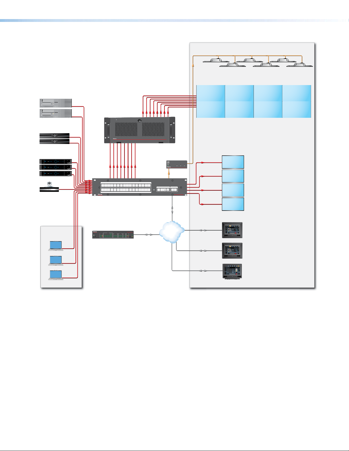
Audio
Extron
FF 220T
Ceiling Speakers
Operations Center
Videowall
CPUs
1234
WiFi
1234
WiFi
Trafc Cam
Receivers
Satellite
Receivers
PUSH PUSH
POWER GUIDE MENU RES480 480p720p1080i1080p
SELECT
DIRECTV
PUSH PUSH
POWER GUIDE MENU RES480 480p720p1080i1080p
SELECT
DIRECTV
PUSH PUSH
POWER GUIDE MENU RES480 480p720p1080i1080p
SELECT
DIRECTV
Codec
Extron
Quantum Connect
Scalable Multi-Graphic
Videowall Processor
System
DBS RECEIVER
DBS RECEIVER
DIRECTV HD
DIRECTV HD
DIRECTV HD
HDMI
HDMI HDMI
HDMI
Extron
DATA
2
1
2
1
INPUTS
10
9
8
4
6 7
3
5
10
9
8
7
3 4
6
5
OUTPUTS
11
11 12
16
12
14 15
13
CONFIG
16
15
14
13
DXP HD 4K
4K HDMI Matrix Switcher
HDMI
HDMI
QUANTUM CONNECT 408
VIDEO WALL PROCESSOR
Extron
MPA 401-70V
Power Amplier
BASSLEVEL TREBLE
MINI POWER AMPLIFIER
Audio
C O N T R O L I/O
ESCVIEW
AUDIOVIDEO
PRESETENTER
DXP HD 4K SERIES
DIGITAL CROSSPOINT MATRIX SWITCHER
Ethernet
Displays
HDMI
MPA 401
HDMI
with Audio De-Embedding
Security
Camera
Operations
Center
SWITCHED
12 VDC
2143LIMIT
R
Tx
Rx
OVER
Extron
1234567
COM
IPCP PRO 550
IR/SERIAL
RELAYS FLEX
eBUS
RTS
I/O
CTS
Tx
Rx
8
1000
1
2156374
LIMIT
1
2
S
LINK
IR
ACT
324
8
563748
OVER
Ethernet
TCP/IP
Network
IPCP Pro 550
IP Link Pro
Control Processor
Ethernet/PoE
Ethernet/PoE
Ethernet/PoE
Display
On
Off
Mute
Screen
Control
Lighting
Control
Security
Camera
Display
On
Off
Mute
Screen
Control
Lighting
Control
Display
On
Off
Mute
Room
Control
Screen
Lighting
Laptops
Extron
Blu-ray
PC Laptop DVD AuxTuner
1 2 3
Volume
Tuner
Presets
Channel
channel
Number
Pad
Bravo
TLP Pro 720M
Mute
Video Preview
Audio
System
May 10, 2011 - 2:48 PM
Help
Control
Off
Extron
7" Wall Mount
TouchLink Pro Touchpanel
Extron
Blu-ray
PC Laptop DVD AuxTuner
1 2 3
Volume
Tuner
Presets
Channel
channel
Number
Pad
Bravo
TLP Pro 720M
Mute
Video Preview
Audio
System
May 10, 2011 - 2:48 PM
Help
Control
Off
Extron
7" Wall Mount
TouchLink Pro Touchpanel
Doc
Tuner
1 2 3
VCRLaptop PC DVD
Cam
Extron
Volume
Tuner
Channel
Presets
321
654
Mute
987
TLP Pro 720T
Last
More
Presets
Enter
0
System
Audio
December 15, 2013 - 7:58 AM
Help
Control
Off
Extron
7" Tabletop
TouchLink Pro Touchpanel
Figure 2. Application Diagram for a Videowall
DXP HD 4K Series • Introduction 5
Page 14

Installation
This section describes the rear panels of the DXP HD 4K switchers and provides
instructions for cabling. It covers the following topics:
• Rear Panels
• Connecting to the LAN Port
• Connecting to the Remote RS-232 Port
• Connecting to the USB Config Port
Rear Panels
Most of the connectors are on the rear panels of the DXP HD 4K switchers. Figures 3 and
4 on the next page show the rear panels of a DXP 88 series model and a DXP 1616 series
model.
WARNING: Remove power from the system before making any connections.
AVERTISSEMENT : Couper l’alimentation avant de faire l’installation électrique.
ATTENTION:
• Use electrostatic discharge precautions (be electrically grounded) when making
connections. Electrostatic discharge (ESD) can damage equipment, although you
may not feel, see, or hear it.
• Prenez des précautions contre les décharges électrostatiques (soyez
électriquement relié à la terre) lorsque vous effectuez des connexions. Les
décharges électrostatiques (ESD) peuvent endommager l’équipement, même si
vous ne pouvez pas le sentir, le voir ou l’entendre.
DXP HD 4K Series • Installation 6
Page 15

DXP 44, 84, and 88 HD 4K
II
H
H
G
G
F
F
E
E
IH
100-240V ~ 1.0A MAX
50-60 Hz
1
5
INPUTS
2
6
A
B
C
3
7
4
8
Input connectors
Output connectors E Remote connector
Reset LED
Figure 3. DXP 88 HD 4K Rear Panel
NOTE: Figure 3 shows a DXP 88 HD 4K. The rear panels of the DXP 44 and DXP 84
models are identical to this model except for the number of inputs and outputs:
• DXP 44 HD 4K — 4 inputs and 4 outputs
• DXP 84 HD 4K — 8 inputs and 4 outputs
• DXP 88 HD 4K — 8 inputs and 8 outputs
DXP 168 and 1616 HD 4K
AA
12
6
5
OUTPUTS
Reset button
D
LAN port
F
BAA
B
DD
C
C
C
CBB
DXP 88 HD 4K
REMOTE LAN
Tx Rx G
3
4
8
7
S/PDIF
1
L
R
2
AUDIO OUTPUTS
Analog audio outputs
G
S/PDIF audio outputs
H
AC power connector
I
RESET
DXP 1616 HD 4K
100-240V ~ 1.1A MAX
50-60 Hz
1
5
9
INPUTS
13
10
14
3
2
6
4
8
7
11
12
INPUTS
15
16
1
5
9
OUTPUTS
13
3
2
6
10
14
4
8
7
11
12
15
16
I
Input connectors
A
Output connectors
B
Reset LED
C
Reset button
D
Remote connector
E
LAN port
F
AUDIO OUTPUTS
1
S/PDIF
OUTPUTS
S/PDIF
Analog audio outputs
G
S/PDIF audio outputs
H
AC power connector
I
H
L
R
2
3
L
R
4
G
G
RESET
Tx Rx G
REMOTELAN
D
D
E
E
F
F
Figure 4. DXP 1616 HD 4K Rear Panel
NOTE: Figure 4 shows a DXP 1616 HD 4K. The rear panel of the DXP 168 HD 4K is
identical to this model except for the number of outputs:
• DXP 168 HD 4K — 16 inputs and 8 outputs
• DXP 1616 HD 4K — 16 inputs and 16 outputs
DXP HD 4K Series • Installation 7
Page 16

Input connectors — Connect HDMI source devices to these female 19-pin type A
LAN
DXP 1616
Series
LAN
DXP 88 Series
A
HDMI input connectors.
LockIt cable lacing brackets, one for each HDMI input and output connector, are
provided with the DXP HD 4K. These brackets can be used to secure the HDMI cables
to the DXP connectors to reduce stress on the HDMI connectors and prevent signal
loss due to loose cable connections.
For information on attaching the LockIt brackets, see the LockIt HDMI Lacing Bracket
Installation Guide card, available on the Extron website at www.extron.com.
Output connectors — Connect HDMI output devices to these female 19-pin type A
B
HDMI output connectors for buffered video output. See the provided LockIt instruction
card to securely fasten an HDMI cable to the DXP using LockIt brackets.
Reset LED — This green LED remains lit while the DXP has power. While the Reset
C
button (D) is being pressed and held, this LED blinks every 3 seconds to indicate the
level of reset that will be initiated if the button is released at that point (see Resetting on
page 47 for more information).
Reset button — This recessed button initiates four levels (modes) of reset on the DXP
D
switcher. To initiate the different reset levels, use a pointed object such as a small Philips
screwdriver or a stylus to press and hold the button while the switcher is running or
while it is being powered up (see Resetting).
Remote connector — Connect a host device, such as a computer or touch panel
E
control, to the switcher via this 3-pole 3.5 mm captive screw connector for serial
RS-232 control (see Connecting to the Remote RS-232 Port on page 11.
Connect the 9-pin connector end of the RS-232 cable to the serial port of your
computer or control system.
LAN port — Connect the DXP switcher to a computer, a network switch, or
F
a control system via this RJ-45 connector. You can use a computer to
configure and control the networked switcher with SIS commands, the PCS
configuration software, or the HTML page that is embedded on the switcher
(see Connecting to the LAN port on page 10).
Ethernet connection indicators — The Link and Act LEDs within the LAN
connector indicate the status of the Ethernet connection. The green Link LED
indicates that the switcher is properly connected to an Ethernet LAN. This
LED should light steadily. The amber Act (Activity) LED indicates transmission
of data packets on the RJ-45 connector. This LED should flicker as the switcher
communicates.
DXP HD 4K Series • Installation 8
Page 17

Analog audio outputs — Connect powered speakers, an amplifier, or other audio
Do not tin the wires!
Slee
No Ground Here
LR
Tip (+)
G
output device to these 5-pole 3.5 mm captive screw connectors for 2-ch stereo analog
audio output. These connectors can de-embed LPCM audio that was routed from any
DXP HDMI input and convert it to a stereo analog signal. Figure 5 shows how to wire
these connectors. Use the supplied tie-wrap to strap the audio cable to the extended
tail of the connector.
Tip
Ring
ves
Tip
Ring
Balanced Audio Output
LR
Tip
Sleeves
Tip
No Ground Here
Unbalanced Audio Output
Figure 5. Wiring the Captive Screw Analog Audio Output Connectors
The DXP 168 and 1616 have four analog audio output connectors while the
DXP 44, 84, and 88 have two.
ATTENTION:
• For unbalanced audio output, connect the sleeves to the ground contact. DO
NOT connect the sleeves to the negative (-) contacts.
• Pour l’audio asymétrique, connectez les manchons au contact au sol. Ne PAS
connecter les manchons aux contacts négatifs (–).
NOTE: The length of exposed wires is important. The ideal length is 3/16 inch
(5 mm).
S/PDIF digital audio outputs (Sony/Philips Digital Interface Format) — Use 75 ohm
H
digital audio cables to connect audio signal processors (such as the Extron SSP
7.1 Surround Sound Processor) or other compatible devices to these female RCA
connectors. The connected processor then converts digital signals from these ports to
analog for encoded standard definition bitstream audio for Dolby or DTS multi-channel
surround sound.
I
Sleeve ( )
Figure 6. RCA Plug for S/PDIF Audio Outputs
AC power connector — Plug a standard IEC power cord (provided) into this
connector to connect the switcher to a 100 VAC to 240 VAC, 50-60 Hz power source.
DXP HD 4K Series • Installation 9
Page 18

Connecting to the LAN Port
Both ends of the cable can be T568B (as shown)
or T568A (not shown).
Crossover Cable Straight-through Cable
When connecting a computer to the DXP LAN port, it is essential that you use the correct
Ethernet cables, and that they be properly terminated with the correct pinout (see figure 7).
Ethernet links use Category (CAT) 3, 5e, or 6 unshielded twisted pair (UTP) or shielded
twisted pair (STP) cables, terminated with RJ-45 connectors. Ethernet cables are limited to
a length of 328 feet (100 m).
NOTES:
• Do not use standard telephone cables. Telephone cables do not support Ethernet
or Fast Ethernet.
• Do not stretch or bend the cables; this can cause transmission errors.
Pins:
12345678
Pin
End 1 End 2End 1End 2
Wire Color
Wire Color
Pin
Wire Color
Wire Color
1
2
3
4
Blue
5
White-blue
6
7
White-brown
8
Brown
T568B
A cable that is wired the same at both ends
is called a "straight-through" cable because
no pin or pair assignments are swapped.
White-orangeWhite-orange
OrangeOrange
White-greenWhite-green
Blue
White-blue
GreenGreen
White-brown
Brown
T568B
Insert Twisted
Pair Wires
RJ-45
Connector
1
White-green
2
Green
3
White-orange
4
Blue
5
White-blue
6
Orange
7
White-brown
8
Brown
T568A
A cable that is wired as T568A at one end
and T568B at the other (Tx and Rx pairs
reversed) is a "crossover" cable.
White-orange
Orange
White-green
Blue
White-blue
Green
White-brown
Brown
T568B
Figure 7. RJ-45 Connector and Pinout Tables
The cable used depends on your network speed. The switcher supports both
10 Mbps (10Base-T — Ethernet) and 100 Mbps (100Base-T — Fast Ethernet), half-duplex
and full-duplex, Ethernet connections.
• 10Base-T Ethernet requires CAT 3 UTP or STP cable at minimum.
• 100Base-T Fast Ethernet requires CAT 5e UTP or STP cable at minimum.
The Ethernet cable must be properly terminated for your application as either a crossover or
a straight-through cable.
• Crossover cable — Direct connection between the computer and the DXP switcher
• Patch (straight-through) cable — Connection of the DXP to a network via a network
switch
DXP HD 4K Series • Installation 10
Page 19

Connecting to the Remote RS-232 Port
ol System
RS-232 Port
The DXP HD 4K switchers have a rear panel Remote serial port through which they can
be configured via SIS commands (serial commands that control the switcher through this
connector).
Wire the 3.5 mm captive screw Remote RS-232 connector as shown in figure 8.
Tx Rx
G
DXP HD 4K
Rear Panel
RS-232 Port
Tx Rx G
NOTES:
• If you use cable that has a drain wire, tie
the drain wire to ground at both ends.
• Connect a ground wire between the DXP
and the computer or control system.
Ground (G)
Receive (Rx)
Transmit (Tx)
Transmit (Tx)
Receive (Rx)
Computer or
Contr
Figure 8. Wiring the Remote RS-232 Connector
See SIS Configuration and Control, starting on page 57, for definitions of the SIS
commands and Configuration Software, starting on page 81, for details on how to install
and use the control software.
NOTES:
• The switcher operates at 9600, 19200, 38400, or 115200 baud.
• See Selecting the Remote RS-232 Port Baud Rate on page 51 to configure this
port using the front panel buttons.
If desired, you can connect an MKP 2000 or MKP 3000 remote control panel to this port.
See the user guide of either product for details.
DXP HD 4K Series • Installation 11
Page 20

Connecting to the USB Config Port
Computer
The USB mini-B Config port is located on the DXP front panel. It provides an alternative
connection for configuring the switcher via SIS commands.
1. Use a USB A to mini-B cable to connect the USB Config port to a USB port on the
computer.
NOTE: Figure 9 shows a DXP 88 4K HD series. The front panels of the DXP 1616
and 168 have the Config port near the center, between the block of input and
output buttons and the control buttons.
USB Mini-B
USB A
USB 1
USB
Ports
USB Cable
DXP 4K HD
Extron
CONFIG
INPUTS
1526374
8
Figure 9. Connecting to the Front Panel USB Config Port
OUTPUTS
1526374
ENTER PRESET ESC I/O
8
VIDEO
SIGNAL
12345678
HDCP
AUDIO
INPUTS
DXP HD 4K SERIES
DIGITAL CROSSPOINT MATRIX SWITCHER
2. If this is the first time you have connected a DXP HD 4K to this particular USB port on
your computer, you may need to download the USB driver for DXP.
DXP HD 4K Series • Installation 12
Page 21

One of the following screens may open:
• Windows XP and earlier — If the following screen is displayed, specify whether
you want the computer to connect to Windows Update in order to search the web
for the driver that it needs to communicate with the DXP via the USB port (this is
not necessary if the USB driver already exists on your computer).
Figure 10. Found New Hardware Wizard Opening Screen
Select one of the following radio buttons:
• Select the Yes, this time only radio button if you want your computer to
connect to Windows Update only this one time.
• Select Yes, now and every time I connect a device if you want the
computer to automatically connect to Windows Update every time the DXP is
connected to this USB port.
• Select No, not this time if you do not want the computer to connect to
Windows Update at this time (for example, if the driver is already installed).
NOTE: This wizard appears only the first time you connect the DXP to each
USB port. You do not see the wizard again unless you connect the DXP to a
different USB port on your computer.
• Windows 7 and later — A pop-up prompt appears on the Windows taskbar
informing you that Windows is searching Windows Update for USB software.
If desired, click the USB icon to view the progress of the search on the Driver
Software Installation window.
NOTE: If you have uploaded the PCS software to your computer, the USB driver is
already installed and the screens do not appear.
DXP HD 4K Series • Installation 13
Page 22

3. Windows XP and earlier — Click Next. On the next screen, make sure that the
Install the software automatically (Recommended) radio button is selected, then
click Next (you do not need to insert a disc).
Figure 11. Selecting the Radio Button to Install the USB Driver Automatically
The computer locates the driver needed for it to communicate with the DXP through the
USB port.
4. Windows XP or earlier — When the Completed screen appears, click Finish to
close the wizard.
Windows 7 or later — When the USB software has been located and downloaded,
the messages Extron USB Device installed and Ready to use appear on the Driver
Software Installation screen (a pop-up message appears above the Windows taskbar if
the screen is closed).
Figure 12. Device Software Installation Window, Installation Complete
Click Close to close the status window.
5. Configure the DXP as desired, using SIS commands (see SIS Configuration and
Control, starting on page 57) or the PCS configuration software (see the program help
file).
DXP HD 4K Series • Installation 14
Page 23

Securing the HDMI Connectors Using the LockIt HDMI Cable Lacing
333
Bracket
After connecting an input or output device to an HDMI
connector, secure the connector in place with the
provided LockIt bracket (see the illustration at right):
1. Plug one or both HDMI cables into the panel
connection (2).
2. Loosen the HDMI connection mounting screw
from the panel enough to allow the LockIt lacing
bracket to be placed over it (2).
3. Place the LockIt lacing bracket onto the screw and
slide it up against the HDMI connectors. Tighten
the screw to secure the bracket (3).
ATTENTION:
• Do not overtighten the HDMI connector mounting screw. The shield to which it
fastens is very thin and can easily be stripped.
• Ne serrez pas trop la vis de montage du connecteur HDMI. Le blindage auquel
elle est attachée est très fin et peut facilement être dénudé.
4. Loosely place the included tie wrap around the HDMI connectors and the bracket (4).
5. While holding the connector securely against the lacing bracket, tighten the tie wrap,
then remove any excess length.
444
111
222
555
DXP HD 4K Series • Installation 15
Page 24

Operation
This section describes the DXP front panel controls and the procedures for configuring and
operating the DXP switchers. Topics include:
• Definitions
• Front Panel Controls and Indicators
• Powering On
• Creating or Changing a Configuration
• Viewing a Configuration
• Saving and Recalling Presets
• Muting and Unmuting Video and Audio Outputs
• Locking and Unlocking the Front Panel (Executive Modes)
• Resetting
• Setting the Button Background Illumination — DXP 1616 Series Only
• Selecting the Remote RS-232 Port Baud Rate
• Troubleshooting
• Configuration Worksheets
Definitions
The following terms, which apply to Extron digital matrix switchers, are used in this guide:
• Tie — An input-to-output connection
• Set of ties — An input tied to two or more outputs. (An output can never be tied to
more than one input.)
• Configuration — One or more ties or sets of ties
• Current configuration — The configuration that is currently active in the switcher (also
called configuration 0)
• EDID (Extended Display Identification Data) — Resolution, refresh rate, pixel clock,
and audio channel configuration information for a display device. This information
is stored in memory at system power-up and each time a new display device is
connected. The EDID is then made available to be assigned to any input.
• Global preset — A configuration that has been stored, consisting of a complete
map of all input and output connections. When a preset is retrieved from memory, it
becomes the current configuration.
• DXP 44, 84, and 88 can store up to 16 presets in memory.
• DXP 168 and 1616 can store up to 32 presets in memory.
• DXP 168 and 1616 can store up to 32 presets in memory.
NOTE: Using SIS commands or the PCS configuration software, you can save and
recall up to the maximum number of presets allowed for your model. However,
from the front panel you can save and recall only as many presets as the model
has input and output buttons.
DXP HD 4K Series • Operation 16
Page 25

• Room — A subset of outputs that are logically related to each other, as determined by
HH
the operator. The switchers support up to 10 rooms, each of which can consist of 1 to
16 outputs. Each room can have up to 10 presets.
• Room preset — A configuration consisting of outputs in a single room that has
been stored. When a room preset is recalled from memory, it becomes the current
configuration for the outputs assigned to that room only (none of the other outputs are
affected). Room presets can be saved and recalled only via SIS commands or the PCS
software.
Front Panel Controls and Indicators
NOTE: When the switcher is in either power-save mode (see Power save mode SIS
commands on page 76), all front-panel indicators are unlit with the exception of the
Video LED or Video button, which blinks continuously.
The buttons on the DXP HD 4K front panels are grouped into two sets, with the input and
output buttons located on the left side of the control panel and the Control and I/O buttons
on the right.
Each DXP model has the same number of input buttons as output buttons, regardless
of how many rear panel input and output connectors it actually has. On models with four
inputs or outputs, buttons 5 through 8 behave like buttons 1 through 4, selecting inputs or
outputs 1 through 4.
The buttons differ for the two DXP HD 4K series as follows:
• DXP 88 HD 4K series — The buttons are black and do not illuminate. At the right of
each button is a bicolor LED that lights to indicate the button status or current function.
• DXP 1616 HD 4K series — The buttons are tri-color, able to illuminate red, green, or
amber. They can be labeled with text or graphics. You can set these buttons to have
amber background illumination when not pressed, or you can disable the background
illumination (see Setting the Button Background Illumination — DXP 1616 Series
Only on page 53).
Depending on the operation, the buttons or LEDs blink or light steadily when pressed.
The front panel buttons have multiple functions, which are classified as primary and
secondary.
Extron
A
A
CONFIG
BB
INPUTS
1526374
8
Config port
A
Input buttons
B
Output buttons
C
Control buttons
D
CC
OUTPUTS
1526374
DD
ENTER PRESET ESC I/O
8
I/O button
E
Audio and Video LEDs
F
Signal LEDs
G
HDCP LEDs
H
EE
AUDIO
VIDEO
FF
SIGNAL
HDCP
GG
INPUTS
12345678
Figure 13. DXP HD 4K 88 Series Front Panel
Figure 13 shows a DXP 88 HD 4K front panel. The DXP 44 and 84 front panels are identical
to this one.
DXP HD 4K Series • Operation 17
DXP HD 4K SERIES
DIGITAL CROSSPOINT MATRIX SWITCHER
Page 26

NOTE: Although the DXP 44 and 84 both have eight input and eight output buttons, not
all these buttons are functional for making ties:
• DXP 44 — Only input and output buttons 1 through 4 are functional, except for
creating and recalling presets (see Saving and Recalling Presets on page 37).
• DXP 84 — All input buttons are enabled, but only output buttons 1 through 4 are
functional, except for creating and recalling presets.
2
1
1
A
B
C
4
3
5
2
4
3
5
Config port
Input buttons
Output buttons
BB
INPUTS
10
9
7 8
6
9
7 8
6
OUTPUTS
10
11
11
12
12
15 16
14
13
15 16
14
13
Control buttons
D
I/O buttons
E
AA
CONFIG
DD EE
C O N T R O L I/O
PRESETENTER
ESCVIEW
AUDIOVIDEO
DXP HD 4K SERIES
DIGITAL CROSSPOINT MATRIX SWITCHER
Figure 14. DXP HD 4K 1616 Front Panel
Figure 14 shows a DXP 1616 HD 4K front panel. The DXP 168 front panel is identical to this
one.
NOTE: Although the DXP 168 has 16 input and output buttons, output buttons 9
through 16 are not functional for making ties. They can, however, be used for creating
and recalling presets (see Saving and Recalling Presets on page 37).
Config port — This USB mini-B port serves a similar communications function to
A
the rear panel Remote port, but is easier to access than the rear port after the matrix
switcher has been installed and cabled. Use a USB type A to mini-B cable to connect
this port to a USB connector on the computer to enable SIS commands to be sent from
the computer, connection to the PCS configuration software, and uploading firmware.
For more information about this port, see Connecting to the USB Config Port on
page 12.
NOTE: A front panel Config port connection and a rear panel Remote port
connection can both be active at the same time. If commands are sent
simultaneously to both ports, the command that reaches the DXP first is handled
first.
Input buttons — The input buttons have the following functions:
B
Primary:
• Select an input.
• Identify the selected input.
Secondary:
• Save and recall presets (see Saving and Recalling Presets).
• Inputs 1 and 2 only — Toggle button background illumination on and off (see
Setting the Button Background Illumination — DXP 1616 Series Only on
page 53).
DXP HD 4K Series • Operation 18
Page 27

Output buttons — The output buttons have the following functions:
C
Primary:
• Select outputs.
• Identify the selected outputs.
Secondary:
• Save and recall presets (see Saving and Recalling Presets on page 37).
• Mute video and audio output (see Muting and Unmuting Outputs from the
Front Panel on page 41).
• De-embed HDMI audio signals from the input.
Control buttons — The three Control buttons have the following functions:
D
• Enter button — The Enter button has the following functions:
Primary:
• Save changes made on the front panel.
• Indicate that a potential tie has been created but not saved.
• Indicate that a preset has been selected to be saved or recalled but the preset
action has not been accomplished.
Secondary:
• Select 9600 baud rate for the Remote RS-232 port.
• Set the front panel lock mode (executive mode).
• With the Preset, View
and Esc > buttons, place the switcher in serial port
<,
configuration mode.
• Indicate that the Remote RS-232 port is set to 9600 baud in serial port
configuration mode (blinking).
• Preset button — The Preset button has the following functions:
Primary:
• Place the switcher in preset saving mode to save a configuration as a preset,
and in preset recalling mode to activate a previously-defined preset.
• Indicate when preset saving mode is active (blinks) and when preset recalling
mode is active (lights steadily).
Secondary:
• Select the 19200 baud rate for the Remote RS-232 port.
• With the Enter, View
, and Esc > buttons, place the switcher in serial port
<
configuration mode.
• Indicate that the Remote RS-232 port is set to 19200 baud in serial port
configuration mode (blinking).
• View button — The View
Primary:
• Place the switcher in view-only mode to display the current configuration.
button has the following functions:
<
NOTE: View-only mode also provides a way to mute and unmute outputs
(see Muting and Unmuting Outputs from the Front Panel on
page 41).
• Indicate that the DXP is in view-only mode.
DXP HD 4K Series • Operation 19
Page 28

Secondary:
• Select the 38400 baud rate for the Remote RS-232 port.
• With the Enter, Preset, and Esc
configuration mode.
• Indicate that the Remote RS-232 port is set to 38400 baud in serial port
configuration mode (blinking).
• Esc button — The Esc
Primary:
• Cancel operations or selections in progress and resets the front panel button
indicators.
button has the following functions:
>
buttons, place the switcher in serial port
>
NOTE: The Esc
presets.
• Indicate that the escape function has been activated (blinks once).
Secondary:
• Select the 115200 baud rate for the Remote RS-232.
• Set the front panel lock mode.
• With the Enter, Preset, and View
configuration mode.
• Select 115200 baud for the Remote RS-232 port in serial port configuration
mode (see Selecting the Remote RS-232 Port Baud Rate on page 51).
• Indicate that the Remote RS-232 port is set to 115200 baud in serial port
configuration mode.
I/O buttons — For these buttons, selecting Video routes HDMI signals from any of
E
the inputs to any of the HDMI outputs, while selecting Audio routes the de-embedded
audio from any of the HDMI inputs to any of the S/PDIF and analog audio outputs.
• DXP 44, 84, and 88 — These models have one I/O button with two LEDs to its
right: a green Video LED and a red Audio LED. Press the I/O button to toggle
between video (green LED lights) and audio (the red LED lights) for the selected
input or output.
• DXP 168 and 1616 — These models have two I/O buttons: Video and Audio.
They select and deselect video and audio for a configuration that is being created
or viewed. The Video button lights green to indicate that video is available for
configuring or for viewing. The Audio button lights red to indicate that audio is
available.
The Audio and Video I/O buttons have the following functions:
Primary:
• Select the signal type, audio or video, for the input or output.
• Select audio or video for the configuration that is being viewed.
button does not reset the current configuration or any
>
buttons, place the switcher in serial port
<
DXP HD 4K Series • Operation 20
Page 29

Secondary:
I
N
P
U
T
S
• Set the front panel lock mode (executive mode).
• View the video or audio mute status of the selected input or output.
• Using the Enter button, select between front panel lock modes (lock mode 2 and
lock mode 0) (see Locking and Unlocking the Front Panel (Executive Modes)
on page 45).
• Select between front panel lock types (lock mode 2 and lock mode 1).
• With the Video and Audio I/O buttons, initiate system reset from the front panel
(see Resetting the System from the Front Panel on page 47).
Audio and Video LEDs (DXP 88 series only) — These two LEDs are located to the
F
right of the I/O button and light to indicate whether the selected input or output is audio
or video. The Video LED lights green when the I/O button is pressed to toggle to video.
The Audio LED lights red when audio is selected.
Signal LEDs (DXP 88 series only) — The DXP 88 series models have a green Signal
G
LED for each input. Each LED lights when a signal (TMDS clock activity) is present on
the input.
HDCP LEDs (DXP 88 series only) — The DXP 88 series models have a green HDCP
H
LED for each input, which lights if the source connected to that input is HDCP
encrypted.
Button Icons — DXP 1616 Series Only
You can temporarily remove the numbered translucent covers of the DXP 1616 and
DXP 168 input and output buttons to insert labels behind the covers.
Input and output labels can be created easily with the Extron Button Label Generator
software, which can be downloaded from www.extron.com. Each input and output
button can be labeled with names, alphanumeric characters, or color bitmaps. See Making
Labels Using the Button Label Generator Program — DXP 1616 Series Only on
page 98 for details on using the labeling software and the procedure for removing and
replacing the translucent covers.
VCR
DVD
Figure 15. Example of Button Labels on a DXP 1616 Series Front Panel
Document
Camera
Computer Computer
13 15
VTG
1312 14 15 16
DXP HD 4K Series • Operation 21
Page 30

Powering On
Apply power by connecting the provided IEC power cord to the rear panel IEC connector
and to an AC source. The switcher performs a self-test as follows:
• DXP 1616 series — The front panel buttons blink green, red, and amber, then turn off.
An error-free power-up self-test sequence leaves all I/O and control buttons either unlit
or showing background illumination.
• DXP 88 series — The front panel input, output, and I/O button LEDs blink red, then
green, while the control button LEDs blink green. All LEDs turn off except the I/O
buttons, which remain lit red for several seconds. An error-free self-test ends with only
one of the I/O LEDs lit, reflecting the previous selection of audio or video.
The current configuration, EDID information, and all presets are saved in memory. When
power is applied, the most recent configuration is retrieved. The previous presets remain
intact. The switcher powers up in full power mode (neither power save mode enabled).
If an error occurs during the self-test, the DXP locks up and does not operate. If this occurs,
call the Extron S3 Sales & Technical Support Hotline (see the last page of this guide for
contact information in your area).
Creating or Changing a Configuration
A configuration consists of one or more inputs, each tied to a set of one or more outputs.
NOTE: While an input can be tied to multiple outputs, an output can be tied to only one
input.
This section contains the steps to follow to create or change a configuration. The following
subsections contain some examples of configurations that can be created on the DXP, and
instructions for setting them up.
To create or change a configuration:
1. Press the Esc > button to clear any input, output, or control button indicators that may
be lit.
2. Select to configure video or audio:
• DXP 88 series — Press the I/O button until the desired LED is lit (green LED for
video or red for audio).
• DXP 1616 series — Press the Video, Audio or both I/O buttons. The Video
button lights green and the Audio button lights red.
3. Select the desired input and outputs by pressing the input and output buttons.
• The input buttons or LEDs light one of the following colors:
• Green — Video only ties
• Red — Audio only ties
• Amber — (DXP 1616 series only) Video and audio ties
DXP HD 4K Series • Operation 22
Page 31

• Output buttons or LEDs light or blink one of the following colors:
ENTER
VIDEO
Press the Esc button to clear all selections.
The LED blinks once.
• Green — Video only ties
• Red — Audio only ties (outputs 1 and 2 on the DXP 88 series, outputs 1
through 4 on the DXP 1616 series)
• Amber — (DXP 1616 series only) Video and audio ties (outputs 1 through 4)
NOTES:
• To indicate potential ties, output buttons or LEDs blink in the appropriate
color when an input is selected.
• To indicate current ties, output buttons or LEDs light steadily in the
appropriate color when an input is selected.
• To clear unwanted outputs, press and release the associated output buttons that
are lit, or whose LEDs are lit. To indicate potential unties, output buttons or LEDs
blink the appropriate color when an output is deselected (muted) but not untied
from the input.
4. Press and release the Enter button to accept the tie or to break an existing tie.
5. Repeat steps 1 through 4 to create or clear additional ties until the desired configuration
is complete.
NOTES:
• Only one input can be tied to an output. If you tie an input to an output that is
already tied to another input, the older tie is broken in favor of the newer tie.
• If an input with no tie is selected, only the button or LED for the selected input
lights (no output buttons or LEDs light).
• As each input and output is selected, the associated output button or LED
blinks the appropriate color to indicate a tentative tie. Buttons or LEDs for
outputs that were already tied to the input light the appropriate color steadily.
Outputs that are already tied can be left on, along with new blinking selections,
or toggled off by pressing the associated output button.
• DXP 1616 series only — When the Video and Audio buttons are lit, if an
input with an audio tie but no video tie is selected, the input button lights amber
and the output button lights the appropriate color (red, green, or amber).
Creating Ties
DXP 88 series
NOTE: Audio ties are made only with de-embedded audio.
To tie an input to an output:
1. Press and release the Esc button to clear any input button, output button, or control
button indicators whose LEDs might be lit.
PRESET ESC I/O
AUDIO
Figure 16. Press the Esc button
DXP HD 4K Series • Operation 23
Page 32

2. Press and release the I/O button to select video or audio as desired.
VIDEO
Pr
select audio or video.
when video is selected.
AUDIO
The LED lights to
indicate the selection.
Press one or more Output buttons.
•
•
(de-embedded audio outputs 1 and 2).
Press the Esc button to clear all selections.
The button blinks once.
NOTE: For the DXP 88 Series, you cannot select both audio and video for a tie at
the same time. You must repeat the tie process for each type of tie (audio and
video) that you want to create for the desired input and output.
For example, first create a video tie between an input and output, then create an
audio tie for the same input and output.
I/O
ess I/O button to
I/O
Lights green
Lights red when audio is selected.
Figure 17. Selecting Audio or Video using the I/O Button
3. Press the desired input button.
1
Figure 18. Selecting an Input for the Tie
4. Press the output buttons to which the input will be tied. Each selected output LED
blinks green for a video tie or red for an audio tie. The Enter LED also blinks to indicate
that a tie has been initiated.
Green blinking LED indicates a video-only tie.
Red blinking LED indicates an audio-only tie
ENTER
1
or
Blinking green LED indicates
the need to confirm the change.
1
Figure 19. Selecting an Output for the Tie
5. Press the Enter button. All button LEDs turn off.
DXP 1616 series
In the following example, input 4 is being tied to outputs 1, 2, and 3.
NOTE: This example assumes that there are no ties in the current configuration.
1. Press and release the Esc > button.
C O N T R O L
PRESET
ENTER
Figure 20. Clear all Selections
ESCVIEW
DXP HD 4K Series • Operation 24
Page 33

2. To select video and audio for the tie, press and release the Video and Audio buttons as
Press the
The b
Press and release an input button.
Press and release the desired Output buttons.
necessary until both the buttons light.
I / O
VIDEO AUDIO
Video button to toggle on and off.
utton lights green when selected.
Press the Audio button to toggle on and off.
The button lights red when selected.
Figure 21. Select Video and Audio
3. Press and release the desired Input button (Input 4 in the example below).
The button lights amber.
INPUTS
1 2 3
4
5
6 7 8
9 10 11 12 14 15 16
13
Figure 22. Select an Input
4. Press and release the Output buttons that will be tied to the selected Input button
(Output buttons 1, 2, and 3 in the example below).
The buttons blink amber to indicate that the selected input will be
tied to these outputs.
INPUTS
1
3
2
4
5
ENTER
9 10 11 12 14 15 16
86 7
OUTPUTS
CONTROL
PRESET
ESCVIEW
13
The Enter button blinks
green to indicate the need to
confirm the change.
Figure 23. Select the Outputs
NOTE: You can cancel the entire set of ties at this point by pressing and releasing
the Esc > button. The Esc > button blinks red once.
DXP HD 4K Series • Operation 25
Page 34

5. Press and release the Enter button.
Press the Enter button to
I/O
confirm the configuration
change.
ENTER
The Enter button
becomes unlit or returns to
background illumination.
All input and output buttons
become unlit or return to
background illumination.
Figure 24. Press Enter to Confirm the Tie
In this example, the configuration now is input 4 video and audio tied to output 1,
output 2, and output 3.
2
2
Figure 25. Final Configuration for the Example
Adding a Tie to a Set of Ties
DXP 88 series
To add a new tie to a configuration:
1. Press and release the Esc button.
2. To select only video for the tie, press and release the I/O button to toggle video on.
The Video LED lights green when video is enabled. Deselect audio by pressing the I/O
button until the Audio LED is unlit (see figure 26).
Press the
I/O
VIDEO
The Video LED lights green when video is selected.
Press the I/O button to toggle audio off.
AUDIO
The Audio LED is unlit when audio is deselected.
button to toggle video on.
Figure 26. Selecting Video Only
To select only audio for the tie, press and release the I/O button to toggle audio on.
The Audio LED lights red when audio is enabled. Deselect video by pressing the I/O
button until the Video LED is unlit.
DXP HD 4K Series • Operation 26
Page 35

3. Press and release the desired input button.
Press and release an Input button.
y outputs already tied to the selected
ENTER
Press and release the Output button to be
The Enter button LED blinks green to
• If only video is selected, its LED lights green to indicate that video outputs can be
tied to or untied from this input. Output button LEDs for any outputs already tied to
the selected input light green also (see figure 27).
The LED lights green to indicate that video
outputs can be tied to or untied from this input.
INPUTS
1
5
2
6
3
7
4
8
The LEDs for an
input light green to indicate the existing video ties.
OUTPUTS
1
5
2
6
3
7
Figure 27. Selecting an Input with Ties (Video)
• If only audio is selected, the LED for the selected input button lights red to
indicate that audio outputs (outputs 1 and 2 only) can be tied to or untied from this
input. If the other audio-capable output is already tied to the selected input, it lights
red also.
4. Press and release the button for the output to be added to the tie. The LED for the
selected output button blinks green (for video only, see figure 28) or red (for audio only)
to indicate that the selected input will be tied to this output.
In addition, the Enter button LED blinks green.
added to the tie.
The LED blinks green to indicate that the
selected video input will be tied to this output.
OUTPUTS
1
2
3
4
4
8
5
6
PRESET ESC I/O
7
8
VIDEO
AUDIO
Figure 28. Selecting an Additional Output (Video)
5. Press the Enter button to confirm the tie. All button LEDs become unlit.
DXP HD 4K Series • Operation 27
Page 36

DXP 1616 series
Press the Esc button to clear all selections.
unlit
background illuminated when deselected.
Press and release the desired Input button.
In this example, a new tie is added to an existing configuration.
1. Press and release the Esc > button.
C O N T R O L
PRESET
ENTER
Figure 29. Clear All Selections
2. To select only video for the tie, press and release the Video and Audio buttons as
necessary until the Video button is lit and the Audio button is off (see figure 30).
ESCVIEW
The button blinks once.
VIDEO
I / O
AUDIO
Press the Video button to toggle video on.
The button lights green when selected.
Press the Audio button to toggle audio off.
The button is
or
Figure 30. Select Video Only
To select only audio for the tie, press and release the Video and Audio buttons as
necessary until the Audio button is lit and the Video button is off.
3. Press and release the desired Input button. Figure 31 shows an example of a video only
tie.
The button lights green to indicate that video
outputs can be tied to or untied from this input.
INPUTS
4
1 2 3
5
6 7 8
9 10 11 12 14 15 16
13
The selected Output buttons light
green to indicate the video ties
previously created.
INPUTS
6 7
3
2
1
5
4
9 10 11 12 14 15 16
8
OUTPUTS
13
Figure 31. Select an Input with Ties
DXP HD 4K Series • Operation 28
Page 37

4. Press and release the button for the output to be added to the configuration (Output 4
Press and release the desired Output button.
uttons
Press the Enter button to
The
becomes unlit or retur
bac
in this example.
The button blinks green to indicate that the
selected video input will be tied to this output.
INPUTS
1
3
2
The Enter button blinks
green to indicate the need to
confirm the change.
4
6 7
5
ENTER
9 10 11 12 14 15 16
8
OUTPUTS
CONTROL
PRESET
ESCVIEW
13
Figure 32. Select an Additional Output
5. Press and release the Enter button.
confirm the configuration
change.
ENTER
Enter button
kground illumination.
All input and output b
become unlit or return to
background illumination.
ns to
Figure 33. Confirm the Tie
In this example, the configuration now is:
• Input 4 video tied to output 1, output 2, output 3, and output 4
• Input 4 audio tied to output 1, output 2, and output 3
2
2
2
Figure 34. Final Configuration for the Example
DXP HD 4K Series • Operation 29
Page 38

Removing a Tie from a Set of Ties
VIDEO
Pr
select audio or video.
when video is selected.
AUDIO
Press and release an Input button.
The LED lights to indicate whether audio or
video w
xample).
Press the Output b
The LED star
DXP 88 Series
To undo an existing I/O tie:
1. Press and release the Esc > button to clear any previous selections.
2. Press the desired I/O button (Video or Audio) for the type of tie you want to break.
I/O
ess I/O button to
I/O
Lights green
Lights red when audio is selected.
Figure 35. Selecting Audio or Video using the I/O Button
3. Press the input button whose tie you want to dissolve. The Input button LED and its tied
Output button LEDs light red (audio) or green (video), depending on your selection in
step 2 and on the types of ties the selected input currently has.
Figure 36 shows an example of selecting an audio-only tie to break.
The LEDs for any outputs already tied to the selected input
as selected for the input.
INPUTS
1
5
2
6
3
7
light to indicate the existing video ties (audio in this e
OUTPUTS
4
8
1
5
2
6
3
7
4
8
Figure 36. Selecting an Input
4. Press the desired output button whose LED is lit. The selected output button LED and
the Enter button LED start to blink.
utton for the tie to be broken.
ts to blink.
OUTPUTS
1
5
2
6
3
7
4
8
ENTER
The Enter button LED blinks green,
indicating the need to confirm the
change.
Figure 37. Selecting the Output to Untie
5. Press the Enter button. The selected input and output buttons or their LEDs and the
Enter button become unlit, and the tie is broken.
DXP HD 4K Series • Operation 30
Page 39

DXP 1616 Series
Press the Esc button to clear all selections.
The button blinks once.
Press and release the desired Input button.
The tied Output b
created pre
To remove a tie from a configuration:
1. Press and release the Esc > button.
C O N T R O L
PRESET
ENTER
Figure 38. Clear All Selections
2. Press and release the Video or Audio button as needed to select the type of tie to be
removed:
• To remove a video tie, press the Video button until it lights green.
• To remove an audio tie, press the Audio button until it lights red.
• To remove a video and audio tie, press both the Video and Audio buttons until
both are lit.
In the example in figure 39, an audio tie is being selected to break.
ESCVIEW
I / O
VIDEO
AUDIO
Press the Video button to toggle video off.
The button is unlit or background
illuminated when deselected.
Press the Audio button to toggle Audio on.
The button lights red when selected.
Figure 39. Selecting an Audio Tie to Break
3. Press and release the Input button from which the tie will be broken (input 4 in the
example in figure 40).
The button lights red in this example
because audio was selected.
INPUTS
1 2 3 5 6 7 8
viously (red for audio in this example).
1
2
4
uttons light to indicate the ties
INPUTS
3
5
9 10 11 12 14 15 16
9 10 11 12 14 15 16
84 6 7
OUTPUTS
13
13
Figure 40. Select an Input
DXP HD 4K Series • Operation 31
Page 40

4. Press and release the Output button for the tie to be broken (output 1 in the example in
Press and release the desired Output button.
The b
e
uttons
Press the Enter button to
The
becomes unlit or retur
background illumination.
figure 41).
utton blinks to indicate the pending change: in this
xample it blinks red because audio input will be untied.
ENTER
8
9 10 11 12 14 15 16
OUTPUTS
CONTROL
PRESET
ESCVIEW
13
1
3
2
4
6 7
5
The Enter button blinks
green to indicate the need to
confirm the change.
Figure 41. Deselect the Output to be Untied
5. Press and release the Enter button.
confirm the configuration
change.
ENTER
Enter button
All input and output b
become unlit or return to
background illumination.
ns to
Figure 42. Confirm the Tie Removal
In this example, the configuration now is:
• Input 4 video tied to output 1, output 2, output 3, output 4
• Input 4 audio tied to output 2 and output 3
• Input 4 video and audio tied to output 2 and output 3
2
2
.
Figure 43. Final Configuration for the Example
DXP HD 4K Series • Operation 32
Page 41

Viewing a Configuration
VIDEO
Pr
select audio or video.
when video is selected.
AUDIO
Press and release an Input b
The LED lights to indicate whether audio or
video w
xample).
You can view the current set of video and audio ties using the front panel buttons. The
view-only mode prevents inadvertent changes to the current configuration. View-only mode
also provides a way to mute outputs (see Muting and Unmuting Outputs from the Front
Panel on page 41).
DXP 88 Series
View the current configuration for the DXP 44, 84, or 88 as follows:
1. Press the Esc button to clear any remaining input, output, or control button selections.
2. Select video or audio by pressing the appropriate I/O button.
I/O
ess I/O button to
I/O
Lights green
Lights red when audio is selected.
Figure 44. Selecting the Type of Ties to View
3. Select the desired input or outputs whose ties you wish to view by pressing the input
and output buttons.
• View ties by selecting an input — Press an input button. All button LEDs light for
the outputs that are tied to the selected input.
utton.
as selected for the input.
INPUTS
1
5
2
6
3
7
The LEDs for any outputs already tied to the selected input
light to indicate the existing video ties (audio in this e
OUTPUTS
4
8
1
5
2
6
3
7
4
8
Figure 45. Viewing Audio Ties
• View ties by selecting an output — Press an output button. The LED for the
tied input and all of the output button LEDs light for outputs that are also tied to the
same input.
NOTES:
• Only outputs 1 and 2 can have audio ties.
• If you press an output button while an input is selected for viewing, the
output LED blinks to indicate a pending tie. Press Esc to cancel the tie or
Enter to add the tie to the selected input.
• View all ties in a configuration — Press and release each input and output
button, one at a time. The output buttons or LEDs light as follows:
• Green — Video-only ties
• Red — Audio-only ties (outputs 1 and 2 only)
DXP HD 4K Series • Operation 33
Page 42

DXP 1616 Series
C O N T R O L
PRESET
ENTER
ESCVIEW
Press the Esc button to clear all selections.
The button blinks once.
To view ties on the DXP 1616 series:
1. Press and release the Esc
>
button.
Figure 46. Clear All Selections
2. Select the input or outputs whose ties you want to view by pressing the input and
output buttons.
• View ties by selecting an input — Press an input button. All buttons light for the
outputs that are tied to the selected input.
• View ties by selecting an output — Press an output button. The button for the
tied input and all of the output buttons light for outputs that are also tied to the
same input.
NOTE:
• Only outputs 1 through 4 can have audio ties.
• If you press an output button while an input is selected for viewing, the
output LED blinks to indicate a pending tie. Press Esc to cancel the tie or
Enter to add the tie to the selected input.
• View all ties in a configuration — Press and release each input and output
button, one at a time. The output buttons light as follows:
• Green — Video-only ties
• Red — Audio-only ties (outputs 1 through 4 only)
• Amber — Audio and video ties (outputs 1 through 4 only)
• Select both video and audio for viewing — Press and release the Video and
Audio buttons as necessary until both are lit.
Press the Video button to
toggle video on and off.
The button lights green
when selected.
I / O
AUDIOVIDEO
Press the Audio button to
toggle audio on and off.
The button lights red when
selected.
INPUTS
3
421
1
NOTE: Until you select an input, the buttons for outputs 1 through 4 light amber if no
3
2
inputs are tied, green if no video inputs are tied (only audio is tied), or red if no audio
inputs are tied (only video is tied).
Outputs 5 through 16 light green if no video inputs are tied (because audio is not
supported on these outputs, they do not light red or amber).
4
6 7
5
5
7
6
9 10 11 12 14 15 16
8
8 9
OUTPUTS
10
11 12 13
13
14
Figure 47. Selecting Video and Audio to View
DXP HD 4K Series • Operation 34
15 16
Page 43

3. Press and release the View < button to put the switcher in view-only mode. The
Press and release an Input button.
The output b
View
• Amber — No tied video or audio input (outputs 1 through 4 only)
• Green — No tied video input
• Red — No tied audio input (outputs 1 through 4 only)
button lights green. All output buttons that are not tied light as follows:
<
Likewise, when you press an output button with no ties, all other output buttons without
ties light.
4. Press and release an input button to view its ties (the Input 4 button was pressed in the
example in figure 48).
NOTE: After 30 seconds of front panel inactivity, the DXP exits view-only mode.
The button lights amber.
INPUTS
1 2 3 5 6 7 8
2
1
The buttons for outputs that are not tied to input 4 are either unlit or background illuminated.
4
3
4
6 7
5
9 10 11 12 14 15 16
The buttons for outputs that are tied to the selected
input light the appropriate color:
• Amber for audio and video ties (audio follow)
• Green for video ties
• Red for audio ties
8
9 10 11 12 14 15 16
OUTPUTS
13
13
Figure 48. Select an Input to View
• To view audio ties only — Press and release the Video button to deselect video.
Press the Video button
to deselect it.
The button is unlit or
The output buttons for outputs that are tied to the
selected input light or blink red to indicate audio ties.
1 4 86 7
background illuminated
when deselected.
3
2
uttons for outputs that are not tied to the selected input are either unlit or background illuminated.
5
I / O
VIDEO
OUTPUTS
The Audio button
remains lit red to
indicate that only
AUDIO
AUDIO
audio is selected.
9 10 11 12 14 15 16
13
Figure 49. Deselecting Video and Selecting Audio to View Only Audio Ties
DXP HD 4K Series • Operation 35
Page 44

• To view video ties only — Press and release the Video button to toggle it to
Press the Audio
The output b
kground illuminated.
kground illumination.
The
unlit or bac
green and the Audio button to toggle it to either unlit or background-illuminated.
Press the Video button
to select it.
The button lights green
when selected.
The output buttons for outputs that are tied to the selected input
(input 4 in this example) light green to indicate video ties.
VIDEO
I / O
AUDIO
button to deselect it.
The button is unlit
or background
illuminated when
deselected.
1
3
2
uttons for outputs that are not tied to the selected input are either unlit or bac
4
6 7
5
9 10 11 12 14 15 16
8
OUTPUTS
13
Figure 50. Deselecting Audio and Selecting Video to View Only Video Ties
If video ties are established for the selected input, the output buttons light green for
all video outputs tied to it. If no ties are established for the selected input, all output
buttons return to either unlit or background illumination.
5. Press and release the View < button to exit view-only mode.
Press the View < button
to exit view-only mode.
VIEW
View < button returns to
kground illumination.
All input buttons and output buttons
return to unlit or bac
Figure 51. Press the View < Button to Exit View-only Mode
NOTE: You can also view a set of ties by selecting a tied output. To show this:
1. Note the number of a lit output button.
2. Press and release the unlit or background-illuminated button for an untied
output. Observe that the buttons for all of the untied outputs light.
3. Press the output button that you noted previously and observe that the
selected output button, the tied input button, and the output buttons light for all
of the outputs that are tied to the input.
DXP HD 4K Series • Operation 36
Page 45

Saving and Recalling Presets
Preset Preset Preset Preset Preset Preset Preset Preset
9 10 11 12 13 14 15 16
17 18 19 20 21 22 23 24 25 26 27 28 29 30 31 32
A preset is a complete map of all input and output connections. The current configuration (0)
can be saved as a preset in any one of 16 preset memory slots (DXP 88 series) or 32 preset
slots (DXP 1616 series). Preset locations are assigned to the input buttons and (where
necessary) output buttons, and each switcher has as many presets available from the front
panel as it has input and output buttons. In addition, all presets can be saved and recalled
from the PCS software and by SIS commands. When a preset is retrieved from memory, it
becomes the current configuration.
NOTES:
• Presets cannot be viewed from the front panel unless recalled as the current
configuration. Presets can be viewed using the PCS configuration program (see the
Configuration Software section, beginning on page 81, for more details).
• The current configuration and all presets are stored in non-volatile memory.
When power is removed and restored, the current configuration is still active and all
presets are retained.
• When a preset is recalled, it replaces the current configuration, which is lost
unless it is also stored as a preset. The recalled preset overwrites all of the current
configuration ties in favor of the preset ties.
• On the DXP 88 series:
• Inputs 1 through 4 correspond to global presets 1 through 4.
• Outputs 1 through 4 correspond to presets 5 through 8.
• Inputs 5 through 8 correspond to presets 9 through 12.
• Outputs 5 through 8 correspond to presets 13 through 16.
1 2 3 4 5 6 7 8
1
INPUTS
2
3
5
Preset Preset Preset Preset Preset Preset Preset Preset
6
7
Figure 52. Preset Locations for DXP 44, 84, and 88
• On the DXP 1616 series, inputs 1 through 16 correspond to presets 1 through 16.
Outputs 1 through 16 correspond to presets 17 through 32.
Preset Preset Preset Preset Preset Preset Preset Preset preset Preset Preset preset Preset Preset Preset Preset
1 2 3 4 5 6 7 8 9 10 11 12 13 14 15 16
1 2 3 4 6 7 8
1 2 3 4 6 7 8
Preset Preset Preset Preset Preset Preset Preset Preset preset Preset Preset preset Preset Preset Preset Preset
5
5
OUTPUTS
Figure 53. Preset Locations for DXP 168 and 1616 Models
OUTPUTS
4
8
INPUTS
9 10 11 12 14 15 16
9 10 11 12 14 15 16
1
5
2
6
13
13
3
7
4
8
DXP HD 4K Series • Operation 37
Page 46

DXP 88 Series — Saving and recalling a preset
PRESET
The LED blinks red to indicate that this
pr
C O N T R O L
PRESET
ENTER
ESCVIEW
Press the Esc button to clear all selections.
The button blinks once.
1. Press the Esc button to clear any previous selections. The Esc LED blinks green once.
2. To save a preset, press and hold the Preset button until the Preset LED starts blinking.
To recall a preset, press and release the Preset button.
Save a
preset
Press and hold.
2 seconds
PRESET
Preset LED blinks.
Recall a
preset
PRESET
Press and release.
PRESET
Preset LED lights.
• All Input and Output button LEDs with assigned presets light red.
• The current preset is overwritten if you select a previously saved
preset.
INPUTS
1
5
2
6
3
7
4
8
1
5
OUTPUTS
2
6
3
7
4
8
Figure 54. Saving or Recalling a Preset (DXP 44, 84, and 88)
3. Press the input or output button for the desired preset number.
NOTE: All input and output buttons can be used for presets, even if they do not
represent actual inputs or outputs on the DXP.
eset is selected to save or recall.
1
ENTER
The Enter LED blinks green
to indicate the need to
activate the save or recall.
Figure 55. Pressing an Input or Output Button to Select a Preset
4. Press the Enter button to confirm.
DXP 1616 Series — Saving a preset
1. Press and release the Esc > button.
Figure 56. Clearing All Selections
DXP HD 4K Series • Operation 38
Page 47

2. Press and hold the Preset button until it blinks (approximately 2 seconds).
Press and hold the Preset button until it blinks.
No Preset Assigned
background illumination.
Press the Enter button to
sa
n to
Press the Esc button to clear all selections.
The button blinks once.
PRESET PRESET
2 seconds
Preset Assigned
INPUTS
All buttons with assigned presets
light.
If you then save the configuration
to a lit preset number, the
configuration data at that preset
location will be overwritten.
1 3 4 6 7 8
2
5
9 10 11 12 14 15 16
13
Figure 57. Entering Save Preset Mode
3. Press and release the input or output button for the desired preset.
Press and release the Input button
for the desired preset number.
The button blinks to indicate that this
preset number is selected but not saved.
2
1
3 4 6 7 8
5
• The Enter button blinks to indicate the
• The Preset button continues to blink.
INPUTS
9 10 11 12 14 15 16
C O N T R O L
ESC
VIEW
PRESET
ENTER
need to save the preset.
13
Figure 58. Selecting the Preset
4. Press and release the Enter button. The current configuration is now stored in the
selected memory location.
ve the preset.
ENTER
C O N T R O L
PRESET
ESCVIEW
All input and output buttons retur
unlit or background illumination.
The Enter and Preset
buttons return to unlit or
Figure 59. Pressing the Enter Button
DXP 1616 Series — Recalling a preset
In the following example, a preset is recalled to become the current configuration. The steps
show the front panel indications that result from your action.
1. Press and release the Esc > button.
C O N T R O L
PRESET
ENTER
Figure 60. Clearing All Selections
ESCVIEW
DXP HD 4K Series • Operation 39
Page 48

2. Press and release the Preset button (the example in figures 61 and 62 shows an audio
Press and release the
Preset Assigned
No Preset Assigned
Press and release the Input b
The b
selected b
All input and output buttons return to unlit or background illumination.
Enter
preset).
Preset button.
The Preset button lights.
PRESET
All buttons with assigned
presets light.
INPUTS
3 4 6 7 8
2
1
5
9 10 11 12 14 15 16
13
Figure 61. Entering Recall Preset Mode
3. Press and release the input or output button for the desired preset.
C O N T R O L
utton for the desired preset.
utton blinks to indicate that this preset number is
ut not recalled.
2
1
3 4 6 7 8
5
PRESET
ENTER
The Enter button blinks to indicate
the need to recall the preset.
INPUTS
9 10 11 12 14 15 16
VIEW
ESC
13
Figure 62. Selecting the Preset
4. Press and release the Enter button. The configuration stored in the selected memory
location is now the current configuration and can be viewed in view-only mode.
Press the
recall the preset.
ENTER ESCVIEW
button to
C O N T R O L
PRESET
1 2 3 4 6 7 8
Figure 63. Pressing the Enter Button
The Enter and Preset
buttons return to unlit or
background illumination.
INPUTS
5
9 10 11 12 14 15 16
13
DXP HD 4K Series • Operation 40
Page 49

Muting and Unmuting Outputs from the Front Panel
VIDEO
Pr
select audio or video.
when video is selected.
AUDIO
links to indicate
Press and hold the desired
NOTES:
• You can mute video and audio, video-only, or audio-only outputs. Pressing and
releasing the Video button and the Audio button toggles each selection on and off.
• When the DXP enters view-only mode, the output LEDs light for all outputs
without ties.
• Mutes are saved to non-volatile memory. When power is removed and
restored, the mute settings are retained.
• Mutes are protected when front panel lock mode 2 is selected. You can view the status
of the output (muted or unmuted) in lock mode 2 but you cannot change it from the
front panel (see Locking and Unlocking the Front Panel (Executive Modes) on
page 45).
• To enable changes to the mute settings, set the lock mode to 0.
DXP 88 Series — Muting and Unmuting Outputs
1. Press Esc to clear any leftover button selections or incomplete ties.
2. Press the I/O button to toggle to your desired selection, Video (green LED lights) or
Audio (red LED lights).
I/O
ess I/O button to
I/O
Lights green
Lights red when audio is selected.
Figure 64. Selecting Audio or Video to Mute
3. Press the button for the output to be muted, and hold it until its LED begins to blink
(approximately 2 seconds). The LED continues to blink until the output is unmuted.
1
Output button.
2 seconds
NOTE: Video is muted in this example.
1
The button b
that the output is muted.
Green = Video is muted.
= Audio is muted.
Red
Figure 65. Muting an Output
To unmute an output, press and hold the blinking output button until the blinking stops
(approximately 2 seconds).
NOTE: In the DXP 44, 84, and 88, if you want to mute an output, but accidentally press
an input button prior to pressing and holding the desired output, this voids the output
muting process and activates the tie process.
DXP HD 4K Series • Operation 41
Page 50

DXP 1616 Series — Muting and Unmuting Outputs
Press the Esc button to clear all selections.
The button blinks once.
The
1. Press and release the Esc > button.
C O N T R O L
PRESET
ENTER
Figure 66. Clearing All Selections
2. Press and release the View < button to enter view-only mode. The View < button
lights green.
Press the View < button
to enter view-only mode.
ESCVIEW
VIEW
View < button lights green.
All untied output buttons light.
Figure 67. Entering View-only Mode
3. To select both video and audio for viewing and muting, if necessary, press and release
the Video and Audio buttons.
7
I / O
AUDIOVIDEO
INPUTS
8
8 9
OUTPUTS
Press the Video button to
toggle video on and off.
The button lights green
when selected.
3
421
1
3
2
4
6 7
5
5
6
Press the Audio button to
toggle audio on and off.
The button lights red when
selected.
9 10 11 12 14 15 16
10
11 12 13
13
14
15 16
Figure 68. Selecting Video and Audio for Viewing and Muting
NOTE: Output mutes are protected when front panel lock mode 2 is selected. You
can view the mutes in lock mode 2 but you cannot change them from the front
panel (see Locking and Unlocking the Front Panel (Executive Modes) on
page 45).
If front panel lock mode 2 is selected and you try to perform steps 4 and 5, the
actions are ignored. Set the lock mode to 0 to enable changes.
DXP HD 4K Series • Operation 42
Page 51

4. One at a time, press and hold the buttons for the outputs to be muted, until each
Mute outputs one at a time.
kground illumination.
Press the View button
The
unlit or bac
illumination.
Unmute outputs one at a time.
vious indication
vious indication
button begins to blink (approximately 2 seconds). The video and audio signals are
muted for all the selected outputs (outputs 3 and 4 in the example in figure 69).
Press and hold the Output 3 button.
3
NOTE: Video is muted in this example.
Press and hold the Output 4 button.
4
2 seconds
2 seconds
The button blinks to indicate
3
that the output is muted.
Green = Video is muted.
Red = Audio is muted.
Amber = Video and audio are muted.
The button blinks to indicate
4
that the output is muted.
Figure 69. Muting Outputs
NOTES:
• If both video and audio are selected, the mute action toggles both the video
and audio outputs. If either the video output or the audio output is already
muted, the unmuted output is muted and the muted output is unmuted.
• If both video and audio are selected and only video is muted, the output button
blinks between green and amber. If only audio is selected, the output button
blinks between red and amber.
5. Press and release the View < button to exit view-only mode.
to exit view-only mode.
VIEW
View button returns to
kground
All input buttons and output buttons
return to unlit or bac
Figure 70. Press the View < Button to Exit View-only Mode
To unmute the outputs:
One at a time, press and hold each output button for approximately 2 seconds until each
button returns to its previous state. The video and audio signals for the selected outputs are
unmuted.
Press and hold the Output 3 button.
3
Press and hold the Output 4 button.
4
2 seconds
2 seconds
The button returns to its pre
(either lit, background illuminated, or unlit)
3
to indicate that the output is unmuted.
The button returns to its pre
(either lit, background illuminated, or unlit)
4
to indicate that the output is unmuted.
Figure 71. Unmuting the Outputs
NOTE: If both video and audio are selected, the unmute action toggles both the video
and audio outputs on and off. If either the video output or the audio output is already
unmuted, the muted output is unmuted and the unmuted output is muted.
DXP HD 4K Series • Operation 43
Page 52

Viewing the Mute Status
To check the mute status of an output:
DXP 88 series
1. Press the Esc button to clear any previous selections.
2. Press the I/O button to select the type of signal to view (video or audio).
3. Press the button for the output to be viewed.
• If the selected output is muted, the button LED blinks red (audio) or green (video),
depending on your viewing selection in step 2.
• If the selected output is not muted, the LED for its button lights steadily.
4. If desired, press the I/O button again to view the mute status of the other signal type.
For example, after viewing the audio mute status of an output and before it times out,
press the I/O button again to view the video status of the same output.
5. To exit the view mode, press Esc
or wait for the indicators to time out.
>
DXP 1616 series
1. Press the Esc button to clear any previous selections.
2. Press the Audio, Video, or both I/O buttons to select the type of signal to view.
3. Press and release the View < button, which lights green. All output buttons that are not
tied light.
4. Press the button for the output to be viewed.
• If only the audio is muted for the selected output:
• If the Audio I/O button was selected, the output button blinks red.
• If the Video button was selected, the output button lights steadily green.
• If both the Video and Audio I/O buttons were selected, the output button
blinks alternating amber and red.
• If only the video is muted for the selected output:
• If the Audio I/O button was selected, the output button lights red.
• If the Video I/O button was selected, the output button or blinks green.
• If both Video and Audio I/O buttons were selected, the output button blinks
alternating amber and green.
• If neither signal is muted for the selected output, the output button lights steadily in
the color indicating its signal type.
DXP HD 4K Series • Operation 44
Page 53

Locking and Unlocking the Front Panel (Executive Modes)
Press and hold simultaneously.
The LEDs blink twice.
Release the buttons.
AUDIO
The matrix switchers have three levels of front panel security lock that limit the operation of
the switcher from the front panel:
• Lock mode 0 — The front panel is completely unlocked. All front panel functions are
available.
• Lock mode 1 — All changes are locked from the front panel (except for setting lock
mode 2). Some functions can be viewed.
• Lock mode 2 — Basic functions are unlocked. Advanced features, except for
switching to lock mode 1, are locked and can only be viewed.
Basic functions include:
• Making ties
• Saving and recalling presets
• Changing lock modes
Advanced functions include:
• Setting video and audio output mutes
• Setting the rear panel Remote RS 232 port protocol and baud rate
NOTE: The switcher is shipped from the factory in lock mode 2.
Selecting Front Panel Lock Mode 2 or Toggling between Lock Modes 2 and 0
NOTES:
• If the switcher is in lock mode 0 or 1, this procedure selects mode 2.
• If the switcher is in lock mode 2, this procedure selects mode 0 (unlocks the
switcher).
DXP 88 series — toggling between lock modes 2 and 0
Toggle the front panel lock on and off by pressing and holding the Enter, I/O, and Esc
buttons simultaneously until the following LEDs blink twice (approximately 3 seconds).
• The Esc, Video, and Audio LEDs blink twice if the DXP is now in lock mode 2.
• The Video and Audio LEDs blink twice if the DXP is now in lock mode 0.
ENTER
3 seconds
ESC
I/O
ESC
I/O
VIDEO
VIDEO
AUDIO
Figure 72. Switching between Front Panel Lock Modes 0 and 2 — DXP 44, 84,
and 88
DXP HD 4K Series • Operation 45
Page 54

DXP 1616 series — toggling between lock modes 2 and 0
Toggle the front panel lock on and off by pressing and holding the Enter, Video, and Audio
buttons simultaneously until the following buttons blink twice (approximately 2 seconds).
• The Esc >, Video, and Audio buttons blink twice if the DXP is now in lock mode 2.
• The Video and Audio buttons blink twice if the DXP is now in lock mode 0.
See figure 73 for a diagram of the procedure.
Lock mode 2
CONTROL I/O
ENTER PRESET
VIEW
ESC
Press and hold for 2 seconds.
Lock mode 0
CONTROL I/O
ENTER PRESET
VIEW
ESC
Press and hold for 2 seconds.
AUDIOVIDEO
AUDIOVIDEO
I/O
AUDIO
VIDEO
AUDIO
CONTROL I/O
ENTER PRESET
VIEW
ESC
VIDEO
AUDIO
AUDIO
Figure 73. Switching between Front Panel Lock Modes 0 and 2 —
DXP 168 and 1616
Selecting Front Panel Lock Mode 2 or Toggling between Lock Modes 2 and 1
NOTES:
• If the switcher is in lock mode 1, this procedure selects mode 2.
• If the switcher is in lock mode 2, this selects mode 1 (locks all switcher functions
except selecting mode 2).
Toggle the lock on and off by pressing and holding the
Video and Audio buttons until the
following buttons blink twice (approximately 3 seconds).
• The Esc, Video, and Audio buttons or LEDs blink twice if the DXP is now in lock
mode 2.
• The Video and Audio buttons or LEDs blink twice if the DXP is now in lock mode 1.
NOTE: To switch from lock mode 1 (front panel is completely locked) to lock mode 0
(front panel is unlocked), you must first switch to mode 2, then from mode 2 to
mode 0.
DXP HD 4K Series • Operation 46
Page 55

Press and hold
The
b
Release the b
DXP 168 and 1616
DXP 44, 84, and 88
LEDs
simultaneously.
ESC
I/O
Press and hold
simultaneously.
I / O
VIDEO
AUDIO
Resetting
3 seconds
ESC
Esc, Video, and Audio LEDs
link twice.
I/O
uttons.
VIDEO
AUDIO
2 seconds
ESC
The Esc, Video, and Audio
blink twice.
Release the buttons.
Figure 74. Toggling between Lock Modes 1 and 2
Switching from Lock Mode 1 to Lock Mode 0
If the switcher is in lock mode 1, you cannot change it directly to lock mode 0 (completely
unlocked). You must first place the switcher in lock mode 2, then toggle it to mode 0
(see Selecting Lock Mode 2 or Toggling Between Mode 2 and Mode 0 beginning on
page 45).
There are several methods by which you can reset the DXP, and some of these methods
allow for four levels of resetting. The following reset methods are available on the DXP:
• Front panel buttons (see Resetting the System from the Front Panel)
• Rear panel Reset button (see Resetting Using the Rear Panel Reset Button on
page 49)
• SIS commands (see the Reset mode commands in the Command and Response
Table for SIS Commands, page 76)
• PCS configuration software (see the program help file)
VIDEO
I / O
AUDIO
Resetting the System from the Front Panel
A system reset (also known as a “hard reset” does the following:
• Clears all ties and presets.
• Clears all video and audio setup and mutes.
NOTE: The system reset does not reset the Internet protocol (IP) settings or replace
user-installed firmware.
The front panel reset is identical to the
commands).
E
ZXXX} SIS command (see the Reset mode
DXP HD 4K Series • Operation 47
Page 56

DXP 88 series — resetting from the front panel
Press and hold the I/O button while
Release the I/O button.
The
b
r
Release the View < and Esc > buttons.
The b
then become unlit.
r
To reset the DXP 44, 84, or 88 switcher to the factory default settings:
1. Press and hold the I/O button while you apply AC power to the switcher.
you apply power to the switcher.
VIDEO
Video and Audio LEDs
link, then become unlit.
I/O
AUDIO
Continue to hold the I/O button until
the Video and Audio LEDs light.
Powe
Figure 75. System Reset, DXP 88 Series
2. Continue to hold the I/O button until the power-up sequence is completed and the
following occurs:
• All LEDs light then go off.
• The Inputs Signal and HDCP LEDs light and remain lit according to the current state
of each input.
DXP 1616 series — resetting from the front panel
To reset the DXP 168 or 1616 switcher to the factory default settings:
1. Press and hold the View < and Esc > buttons while you apply power to the switcher.
Press and hold the View < and Esc >
buttons while you apply power to the switcher.
I / O
uttons blink,
VIEW ESC
100-240V ~ --A MAX
50-60 Hz
Continue to hold the View < and Esc >
buttons until all input and output buttons
blink and return to either unlit or to
background illumination.
Powe
Figure 76. System Reset, DXP 1616 Series
2. Continue to hold the View < and Esc > buttons until the power-up sequence is
completed and all buttons blink and turn off.
DXP HD 4K Series • Operation 48
Page 57

Resetting Using the Rear Panel Reset Button
The rear panel has a recessed Reset button (see figures 3 and 4, D) that initiates various
levels of soft resets, which restore various tiers of switcher settings to their defaults. For
different reset levels, press and hold the button while the switcher is running or press and
hold the button while you apply power to the switcher.
small screwdriver to press the button.
ATTENTION:
• Review the reset modes in the table on the next page carefully. Using the wrong
reset mode could result in unintended loss of flash memory programming, port
reassignment, or a controller reboot.
• Étudier attentivement les différents modes de réinitialisation voir tableau page
suivante. Appliquer le mauvais mode de réinitialisation peut causer une perte
inattendue de la programmation de la mémoire flash, une reconfiguration des ports
ou une réinitialisation du processeur.
NOTES:
• The reset modes listed in the table close all open IP and Telnet connections and all
sockets.
• The modes described in the table are separate functions, not a continuation from
mode 1 to mode 5.
• There is no reset mode 2 for DXP HD 4K.
• Since DXP HD 4K switchers do not support events, reset mode 3 is also
unavailable. If you attempt to initiate it, the Reset LED blinks 3 times but no reset is
performed.
Use a pointed stylus, ballpoint pen, or
The table on the next page provides a summary of the reset modes.
DXP HD 4K Series • Operation 49
Page 58

Reset Modes Summary for DXP HD 4K Series
Mode Activation Result Purpose/Notes
1 Hold in the recessed
Reset button
while applying power to the switcher.
• Restores the factory-installed
firmware for a single power cycle.
• Event scripts do not start.
• Maintains all user files and settings
(drivers, audio adjustments, IP
Use mode 1
to revert to the
factory firmware
if incompatibility
issues arise.
settings, and so on) are maintained.
• It does not clear the current
configuration.
4 Hold in the
Reset LED blinks twice (once after
approximately 3 seconds and
again after 6 seconds). Then, within
1 second press Reset momentarily (for
less than 1 second).
Reset button until the
• Sets the IP address, subnet address,
and gateway address to the factory
defaults.
• Sets port mapping to the factory
default.
• Turns DHCP off.
Mode 4 resets
all IP settings to
factory defaults.
It does not replace
any user-installed
firmware.
• Turn event scripts off.
The Reset LED blinks four times in quick
succession during the reset.
5 Hold in the
Reset LED blinks three times (once
after approximately 3 seconds, again
after 6 seconds, and then again after
9 seconds); then within 1 second
press Reset momentarily (for less than
1 second).
Reset button until the
Performs a complete reset to factory
defaults (with the exception of the
firmware), which includes:
• Everything mode 4 does
• Reset of all real time adjustments:
• Clears all ties, presets, and audio or
RS-232 mutes.
• Resets all IP options.
• Removes or clears all switcher files.
The reset LED blinks four times in quick
Mode 5 is useful
if you want to
start over with
configuration and
uploading and also
to replace events.
Equivalent to
SIS command
E
ZQQQ
}
.
succession during the reset.
DXP HD 4K Series • Operation 50
Page 59

To perform a hardware reset of the switcher:
Absolute Reset
(Mode 5)
DXP 1616 Series
Press and hold
1. Use a stylus or small Philips screwdriver to press and hold the rear panel Reset button
until the front panel Video and Audio buttons blink twice (for a system reset) or three
times (for an absolute reset).
the Reset button.
Reset LED blinks twice.
Release, then immediately
press and release again.
IP Settings
Reset
(Mode 4)
Press and hold
the Reset button.
6 seconds
RESET
Front panel I/O buttons or LEDs blink twice.
VIDEO
I/O
AUDIO
DXP 88 Series
Reset LED blinks
three times.
9 seconds
RESET
Front panel I/O buttons blink three times.
VIDEO
I/O
AUDIO
DXP 88 Series
RESET
DXP 1616 Series
RESET
Figure 77. Soft Resets (Modes 4 and 5)
RESET
I / O
AUDIOVIDEO
Release, then immediately
press and release again.
RESET
I / O
AUDIOVIDEO
2. Release the Reset button and then immediately press and release it again. Nothing
happens if the second momentary press does not occur within 1 second.
Selecting the Remote RS-232 Port Baud Rate
NOTES:
• The serial port settings are protected when front panel lock mode 2 is selected. You
can view the settings in lock mode 2 but you cannot change them from the front
panel.
• To enable changes to the baud rate settings, set the lock mode to 0.
To view and configure the serial communications settings for the switcher from the front
panel:
1. Simultaneously press and hold all Control buttons (Enter, Preset, View [DXP 168
and 1616 only] and Esc) until all of the Control buttons or their LEDs light, as well as
input buttons 1 and 2 (approximately 2 seconds).
DXP HD 4K Series • Operation 51
Page 60

2. Press the appropriate Control button to select the baud rate:
The Control b
Enter
Vie
ENTER
DXP 44, 84, and 88
Pr
DXP 168 and 1616
Press and
View
• Enter = 9600
• Preset = 19200
• View = 38400 (DXP 168 and 1616 only)
NOTE: On the DXP 88 series, this rate can be selected via SIS commands (see
the Serial port configuration commands on page 80).
• Esc = 115200
The selected Control button or its LED blinks.
ess and hold simultaneously.
PRESET
hold the Enter, Preset,
, and Esc buttons.
C O N T R O L
PRESET
ENTER
utton or LED that continues blinking indicates the baud rate as follows:
– 9600 Preset – 19200
w – 38400 (DXP 168 and 1616 only) Esc – 115200
ESC
2 seconds
ESCVIEW
2 seconds
All Control buttons light with one blinking.
ENTER
All Control LEDs light with one blinking.
C O N T R O L
ENTER
PRESET
PRESET
ESCVIEW
ESC
Figure 78. RS-232 Baud Rate Display
3. Release the Control buttons.
4. Press and release an output button to exit the Serial Port Configuration mode.
To change a value, press and release the control button that relates to the desired value.
The selected buttons blink and the others remain lit.
DXP HD 4K Series • Operation 52
Page 61

Setting the Button Background Illumination — DXP 1616 Series Only
Press and hold the Input 1 and Input 2 buttons
simultaneously to toggle bac
mode on or off
The buttons on the front panel can be set to have amber background illumination at all times
or the background illumination can be turned off.
To toggle the background illumination on and off, press and hold the Input 1 and Input 2
buttons simultaneously until the button background illumination changes (approximately
2 seconds.
Troubleshooting
.
1 2 3 4 6 7 8
1 2 3 4 6 7 8
After approximately 2 seconds, release the Input 1 and Input 2 buttons.
Figure 79. Toggle Background Illumination On or Off
The following are recommendations for actions to take if you have problems operating the
switcher:
1. Ensure that all devices are plugged in and powered on. The switcher is receiving power
if the Reset/Power LED is lit.
2. Check to see if one or more outputs are muted.
3. Ensure that an active input is selected for output on the switcher.
4. Ensure that the proper signal format is supplied.
5. Check the cabling and make corrections as necessary.
6. Call the Extron S3 Sales & Technical Support Hotline if necessary.
kground illumination
5
5
INPUTS
9 10 11 12 14 15 16
9 10 11 12 14 15 16
OUTPUTS
13
13
Configuration Worksheets
Instead of trying to remember the configuration for each preset, use worksheets to record
this information. Make copies of the blank worksheet on page 56, and use one sheet
for each preset configuration. Cross out all unused or inactive inputs and outputs. The
worksheet is generic for all models of DXP. Disregard or cross out boxes for inputs and
outputs that your switcher does not have.
NOTE: The worksheet examples on these pages use a form that is set up for a
DXP 1616, you can use the same worksheet form provided on page 56 for all models
of the DXP HD 4K. Use only the input and output cells that you need to configure your
own system.
DXP HD 4K Series • Operation 53
Page 62

Worksheet Example 1: System Equipment
Input Sources
51
Figure 80 shows a worksheet for a DXP in a fictional organization with the system hardware
annotated. Output 7 has no connection in this organization, so it has been crossed out on
the worksheet.
4K
4K
4K
Camera
Camera
1
Main
podium
1 2 345678
1
Camera
2
PC
1
3
Media
Player
VTG
400DVI
1
Station
1
Editing
Station
12345678
Main hall1Main hall2Podium
monitor
1
Conf.
Room
Podium
monitor
1
Demo
Room
2
1
Lobby
monitor
4K
Camera
5
Media
Player
4K
Camera
2
4
Main
podium
PC
2
2
910111213141
9
10 11 12 13 14 15 16
Main hall3Main hall4Podium
1
monitor
2
Conf.
Room
2
Media
Player
3
Podium
monitor
4
Media
Player
4
Demo
Room
2
Editing
Output Destinations
Preset # Title: Video ties:
Fill in the preset number and use colors, dashes, and so forth, to make connecting lines.
Weekly status mtg 3
Figure 80. Worksheet Example 1: System Equipment
Inputs include media players, PCs, editing stations, 4K cameras, and an Extron
VTG 400DVI. Output devices include various 4K monitors.
The VTG 400DVI video test generator connected to input 6 enables a video test pattern to
be sent to one, several, or all output devices for problem isolation or adjustment purposes.
Editing
Station
3
Editing
Station
4
Lobby
monitor
2
6
DXP HD 4K Series • Operation 54
Page 63

Worksheet Example 2: Daily Configuration
51
51
Figure 81 continues from worksheet example 1 by showing the video ties that make up the
configuration of preset 1. A solid ink line shows video ties.
Input Sources
Editing
4K
4K
4K
Camera
Camera
1
Main
podium
1 2 345678
1
Camera
2
PC
1
3
Media
Player
VTG
400DVI
1
Station
1
Editing
Station
2
Editing
4K
Camera
4
4K
Camera
5
4K
Camera
6
Media
Player
2
Media
PC
2
Player
3
Station
910111213141
Editing
Station
3
4
6
12345678
Main hall1Main hall2Podium
monitor
1
Conf.
Room
Podium
monitor
1
Demo
Room
2
1
Lobby
monitor
9
10 11 12 13 14 15 16
Main hall3Main hall4Podium
monitor
2
Conf.
Room
Podium
Demo
monitor
2
Room
3
2
Lobby
monitor
2
Output Destinations
Figure 81. Worksheet Example 2: Daily Configuration
In this example:
• The image of the presenter, from the main podium camera (input 1), is:
• Displayed in the main hall (output 1)
• Displayed in the conference room (output 4) to the overflow crowd
• Displayed in the Demo Room (output 6)
• Displayed in the lobby (output 8)
• The presenter has a presentation stored on PC 1 (input 4) that is:
• Displayed in the main hall (output 2)
• Displayed locally on podium 1 (output 3).
Worksheet Example 3: Test Configuration
The AV system in our fictional organization needs to be fine tuned on a regular basis.
Figure 82 shows a typical test configuration, with an Extron video test generator (input 6)
generating a test pattern to all monitors (outputs 1, 2, 3, 4, 8, and 16).
Input Sources
4K
4K
4K
Camera
Camera
1
Main
podium
1
1 2 345678
Camera
2
PC
1
3
Media
Player
1
VTG
400DVI
Station
1
Editing
Editing
Station
2
4K
4K
Camera
4
Camera
5
4K
Camera
6
Media
PC
Player
2
2
910111213141
Media
Player
3
Editing
Station
3
Editing
Station
4
6
12345678
Main hall
Main hall
Podium
Conf.
monitor
1
monitor
2
monitor
1
Room
Podium
monitor
1
Demo
Room
2
1
Lobby
monitor
9
Main hall3Main hall4Podium
1
Output Destinations
Weekly status mtg
Preset # Title: Video ties:
Fill in the preset number and use colors, dashes, and so forth, to make connecting lines.
3
Figure 82. Worksheet Example 3: Test Configuration
10 11 12 13 14 15 16
Conf.
monitor
2
Room
Podium
monitor
2
Demo
Room
3
2
Lobby
monitor
DXP HD 4K Series • Operation 55
2
Page 64

Input Sources
eset #
Fill in the preset number and use colors, or dashes, and so on, to make connecting lines. Disr
your switcher
1 2 345678 910111213141516
Worksheet Form
1 2 345678 910111213141516
DXP HD 4K Series • Operation 56
Output Destinations
Pr
Title:
.
DXP HD 4K Configuration Worksheet
egard or cross out the input and output boxes that do not apply to
Page 65

SIS Configuration and Control
The DXP HD 4K Series can be configured and controlled with Extron Simple Instruction Set
(SIS) commands. This section describes the communication between a connected host
computer or other control device (such as a control system) and the device. Topics include:
• Connection Methods
• Host and Matrix Switcher Communication
• SIS Overview
• Command and Response Table
Connection Methods
Attach the host device to one of the following connectors:
• Remote RS-232 connector (see figure 3, E, or figure 4, E, on page 7)
• LAN connector (see figure 3, F, or figure 4, F, on page 7)
• USB connector (see figure 13, A, on page 17, or figure 14, A, on page 18)
Commands can be entered using a Telnet application such as the Extron DataViewer,
available at www.extron.com (see the DataViewer Help file for more details).
Host and Matrix Switcher Communication
SIS commands consist of one or more characters per field. No special characters are
required to begin or end a command sequence. Commands can be entered
back-to-back in a string with no spaces. When the switcher determines that a command
is valid, it executes the command and sends a response to the host device. All responses
from the switcher to the host end with a carriage return and a line feed (CR/LF = ]),
indicating the end of the response character string (one or more characters).
Copyright Information
The copyright message is displayed upon connecting to a switcher via TCP/IP or Telnet or
after a power cycle via RS-232, and depends on the switcher model.
] (c) Copyright YYYY, Extron Electronics, [model], Vn.nn, 60-nnnn-nn]
Ddd,
DD MMM YYYY HH:MM:SS ] (day, date, and time as in Mon, 18 May 2015 11:27:33)
[model] is the device name.
Vx.xx
is the firmware version number.
60-nnnn-nn is the model part number.
YYYY is the year.
DXP HD 4K Series • SIS Configuration and Control 57
Page 66

Device-Initiated Messages
When a local event such as a front panel selection or adjustment takes place, the matrix
switcher responds by sending a message to the host. No response is required from the
host. Example switcher-initiated messages are listed here.
• ]
Password:
The ]Password: prompt requires a password (administrator level or user level)
followed by a carriage return. The prompt is repeated if the correct password is not
entered. If the correct password is entered, the unit responds with
]Login Administrator ] or ] Login User], depending on the password
entered. If passwords are the same for both administrator and user, the switcher
defaults to administrator privileges.
NOTE: The password prompt is redisplayed if an incorrect password is entered.
• Qik ]
The switcher initiates the Qik message when a front panel switching operation occurs.
• Rprnn ]
The switcher initiates the Rpr message when a memory preset is recalled from the front
panel. nn is the preset number.
• Sprnn]
The switcher initiates the Spr message when a memory preset is saved from the front
panel. nn is the preset number.
• nnVmtx]
The switcher initiates the Vmt message when a video output mute is toggled on or off
from the front panel. nn is the output number. x is the mute status (0 = off, 1 = on).
• nnAmtx]
The switcher initiates the Amt message when an audio output mute is toggled on or off
from the front panel. nn is the output number. x is the mute status (0 = off, 1 = on).
• Exen]
The switcher initiates the Exe message when the Front Panel Lockout mode is toggled
on or off from the front panel. n is the mode (0 = off, 1 = view only, 2 = basic mode only)
• HplgOnn]
The switcher initiates the HplgO message when a hot plug event is detected on an
output. nn is the output number.
DXP HD 4K Series • SIS Configuration and Control 58
Page 67

Error Responses
When the switcher receives a valid command, it executes the command and sends a
response to the host device. If the unit is unable to execute the command, it returns an error
response to the host.
Error codes
E01 — Invalid input number
E10 — Invalid command
E11 — Invalid preset number
E12 — Invalid output number
E13 — Invalid parameter
E14 — Not valid for this configuration
E17 — Timeout (caused only by direct write
E21 — Invalid room number
E22 — Busy
E24 — Privilege violation
E25 — Device not present
E26 — Maximum number of connections
exceeded
E28 — Bad filename or file not found
of global presets)
Error response references
These references in the command and response tables note particular error responses to
that command.
24
= Commands that give an E24 (privilege violation) error if not administrator level
Connection Timeouts
An Ethernet link disconnects after a designated period of no communications. By default,
this timeout duration is 5 minutes (see the Port timeout commands on page 78 to change
this value).
NOTE: Extron recommends periodically issuing query commands (see the Information
requests commands on page 77) to keep the connection active. If there are long
idle periods, Extron recommends disconnecting and reopening the connection when
another command must be sent.
Number of Connections
A DXP HD 4K Series switcher can have up to 200 simultaneous TCP connections, including
all http and Telnet connections. When the connection limit is reached, the switcher accepts
no new connections until some have been closed. No error message or indication is given
that the connection limit has been reached. To maximize performance, keep the number of
connections low and close unnecessary ones.
DXP HD 4K Series • SIS Configuration and Control 59
Page 68

SIS Overview
Space
Using the Command and Response Table
The Command and Response Table beginning on page 67 lists the commands that the
switcher recognizes as valid, the responses that are returned to the host, a description
of the command function or the results of executing the command, and examples of
commands in ASCII.
NOTE: Upper and lower case text can be used interchangeably unless otherwise
stated.
ASCII to Hex Conversion Table
•
Figure 83. ASCII to Hexadecimal Character Conversion Table
Verbose Mode
The connection to a DXP switcher can be used to monitor for changes that occur on the
switcher, such as front panel operations and SIS commands from a TCP/IP connection
or the RS-232 serial port. To receive change notices from the switcher, you must enable
verbose mode 1 or 3 (see the Verbose mode commands on page 76). In verbose mode 1
or 3, changes are reported in messages that resemble SIS command responses.
DXP HD 4K Series • SIS Configuration and Control 60
Page 69

Symbol Definitions
• = Space
= Carriage return with line feed
]
} or |
E or W
= Carriage return with no line feed
= Escape key
24
= Superscripts indicate the error message displayed if the command is entered
incorrectly or with invalid parameters (see Error Responses on page 59).
X!
= Input number 0 = untie (for ties If applicable)
1-<maximum number of inputs>
X@
= Output number 0 = untie (for ties if applicable)
1-<maximum number of outputs>
X#
= Enable or disable 0 = disable
1 = enable
X$
Name 16 alphanumeric characters (12 characters for
=
room names)
NOTE: The pipe (|) character cannot be used in names. All other
characters, including symbols and spaces, are permitted.
X%
= Input video format 0 = no signal detected
1 = DVI RGB 444
2 = HDMI RGB 444 Full
3 = HDMI RGB 444 Limited
4 = HDMI YUV 444 Full
5 = HDMI YUV 444 limited
6 = HDMI YUV 422 Full
7 = HDMI YUV 422 Limited
X^
X&
X*
X(
X1)
X1!
HDCP Authorized device
=
Input HDCP status
=
Output format
=
Color bit depth
=
HDCP mode
=
Output HDCP status
=
0 = block HDCP encryption
1 = allow HDCP encryption (default)
0 = no source detected
1 = source is HDCP compliant
2 = source is not HDCP compliant
0 = no signal detected
1 = DVI RGB 444
2 = HDMI RGB 444 Full
3 = HDMI RGB 444 Limited
4 = HDMI YUV 444 Full
5 = HDMI YUV 444 limited
6 = HDMI YUV 422 Full
7 = HDMI YUV 422 Limited
8 = pass through
0 = auto (default)
1 = 8-bit
0 = auto (follow the input, default)
1 = on (always encrypt HDMI outputs)
0 = no sink detected
1 = sink does not support HDCP
2 = sink supports HDCP but currently not
encrypted
3 = sink supports HDCP and is currently
encrypted
DXP HD 4K Series • SIS Configuration and Control 61
Page 70

X1@
X1#
X1$
X1%
X1^
X1&
X1*
X1(
X2)
X2!
X2@
X2#
X2$
X2%
X2^
X2&
X2*
X2(
X3)
Video mute
=
Audio mute
=
Output mute
=
Input attenuation
=
Output volume
=
Global preset number DXP 1616 Series:
=
Room number
=
Room preset number
=
Front Panel Lockout mode
=
HDCP notification
=
Signal status
=
Verbose mode
=
Power save mode
=
Firmware version
=
Verbose firmware version
=
Power supply In voltage
=
Temperature In degrees Celsius
=
Fan In RPM
=
IP address
=
0 = unmute
1 = video mute
2 = video and sync mute
0 = unmute
1 = HDMI audio mute
2 = Analog audio mute
3 = HDMI and analog audio mute
4 = S/PDIF mute
5 = HDMI audio and S/PDIF mute
6 = Analog audio and S/PDIF mute
7 = HDMI audio, analog audio, and S/PDIF
mute
0 = unmute
1 = video mute (one or more outputs)
2 = audio mute (one or more outputs)
3 = video and audio mute (one or more outputs)
-20 to 00 in dB (00 = default)
0 to 100 percent in approximately 1 dB intervals
(100 = default)
DXP 88 Series: 1-16
1-10
1-10
0 = unlock the front panel
1 = mode 1 (complete front panel lockout)
2 = mode 2 (tie configuration and preset
management only, default)
0 = black
1 = green
0 = no signal detected
1 = input signal detected
0 = clear or none (default for Telnet connections)
1 = verbose mode (default for RS-232 and
USB connections)
2 = tagged responses for queries
3 = verbose mode and tagged queries
0 = normal operation
1 = limited functionality,
see mode 1 Definition on page 76
2 = limited functionality,
see mode 2 Definition on page 76
n.nn
[version]-[description]-[upload date
and time]
nnn.nnn.nnn.nnn
(192.168.254.254 = default)
1-32
DXP HD 4K Series • SIS Configuration and Control 62
Page 71

X3!
X3@
X3#
X3$
X3%
X3^
X3&
X3*
X3(
X4)
X4!
X4@
Subnet mask
=
Gateway address
=
MAC address
=
Open connections
=
Port timeout
=
Device name Maximum 63 alphanumeric characters or
=
Date and time In the format
=
Date and time (view only) In the format
=
GMT offset
=
Time zone Time zone code (see the View time zone
=
Time zone description
=
Password 128 characters maximum
=
nnn.nnn.nnn.nnn (255.255.0.0 = default)
nnn.nnn.nnn.nnn (0.0.0.0 = default)
00-05-A6-xx-xx-xx
0-<maximum number of open connections>
1 to 65000 in 10-second intervals (30 = default)
hyphens. The first character must be an alpha
character. The last character must not be a
hyphen. No blank or space characters are
permitted. Uppercase and lowercase letters are
interchangeable.
MM/DD/YY•HH:mm:SS
MM = month: 01 (January) to 12 (December)
DD = day: 01 to 31 (depending on the month)
YY = year: 00 to 99 (last two digits)
HH = hour: 00 to 23
mm = minute: 00 to 59
SS = second: 00 to 59
DAY,•DD•MMM•YYYY•HH:mm:SS
DAY
=day of the week: Mon to Sun
DD
= date: 01 to 31 (depending on the month)
MMM
= month: 01 to 12
YYYY = year: 2000 to 2099
HH
= hour: 00 to 23
mm
= minute: 00 to 59
SS
= second: 00 to 59
-12:00 to +14:00
command on page 79 to view a list of available
time zones). The code is followed by an
response.
In the format
This is the UTC equivalent for a particular time
zone as well as a general description of the
geographical area.
(UTCX3()•<Description>
* in the
X4#
NOTE: The pipe (|) character is invalid for passwords.
Filename Can carry a full path name. EDID file format is
=
.bin, carrying 128 or 256 bytes of binary data.
DXP HD 4K Series • SIS Configuration and Control 63
Page 72

X4$
EDID reference file for DDC
=
9 = 720p @ 60 Hz (default)
See the EDID tables, starting below.
DXP 44 and 84
DXP 88
DXP 168
DXP 1616
1–17 = fixed factory rates
18–21 = not selectable (outputs)
26–33 = user assignable
1–17 = fixed factory rates
18–25 = not selectable (outputs)
26–33 = user assignable
1–17 = fixed factory rates
18–25 = not selectable (outputs)
34–49 = user assignable
1–17 = fixed factory rates
18–33 = not selectable (outputs)
34– 49 = user assignable
DXP 44 and 84 EDID Table — DDC Source Selection
SIS
Value
Resolution
or Source/
Destination
Refresh
(Hz)
SIS
Value
X4$
Resolution
Refresh
(Hz)
2ch Audio **Outputs
1 1280x800 60 18 Output 1
2 1440x900 60 19 Output 2
3 1600x900 60 20 Output 3
4 1680x1050 60 21 Output 4
5 1920x1200 60 User Loaded Slots
6 2560x1440 60 26 User assigned
7 2560x1600 60 27 User assigned
8 720p 50 28 User assigned
*9 720p 60 29 User assigned
10 1080p 50 30 User assigned
11 1080p 60 31 User assigned
12 4K/UHD 30 32 User assigned
S/PDIF Audio 33 User assigned
13 720p 50
14 720p 60
15 1080p 50
16 1080p 60
17 4K/UHD 30
*Default EDID
**Stored from connected output monitors as reference
DXP HD 4K Series • SIS Configuration and Control 64
Page 73

DXP 88 EDID Table — DDC Source Selection
SIS
Value
X4$
Resolution
or Source/
Destination
Refresh
(Hz)
SIS
Value
X4$
Resolution
2ch Audio **Outputs
1 1280x800 60 18 Output 1
2 1440x900 60 19 Output 2
3 1600x900 60 20 Output 3
4 1680x1050 60 21 Output 4
5 1920x1200 60 22 Output 5
6 2560x1440 60 23 Output 6
7 2560x1600 60 24 Output 7
8 720p 50 25 Output 8
*9 720p 60 User Loaded Slots
10 1080p 50 26 User assigned
11 1080p 60 27 User assigned
12 4K/UHD 30 28 User assigned
S/PDIF Audio 29 User assigned
13 720p 50 30 User assigned
14 720p 60 31 User assigned
15 1080p 50 32 User assigned
16 1080p 60 33 User assigned
17 4K/UHD 30
Refresh
(Hz)
*Default EDID
**Stored from connected output monitors as reference
DXP HD 4K Series • SIS Configuration and Control 65
Page 74

DXP 168 and 1616 EDID Table — DDC Source Selection
SIS
Value
X4$
2ch Audio **Outputs — DXP 1616 only
S/PDIF Audio 37 User assigned
**Outputs — Both Models 43 User assigned
Resolution
or Source/
Destination
1 1280x800 60 26 Output 9
2 1440x900 60 27 Output 10
3 1600x900 60 28 Output 11
4 1680x1050 60 29 Output 12
5 1920x1200 60 30 Output 13
6 2560x1440 60 31 Output 14
7 2560x1600 60 32 Output 15
8 720p 50 33 Output 16
*9 720p 60 User Loaded Slots
10 1080p 50 34 User assigned
11 1080p 60 35 User assigned
12 4K/UHD 30 36 User assigned
13 720p 50 38 User assigned
14 720p 60 39 User assigned
15 1080p 50 40 User assigned
16 1080p 60 41 User assigned
17 4K/UHD 30 42 User assigned
18 Output 1 44 User assigned
19 Output 2 45 User assigned
20 Output 3 46 User assigned
21 Output 4 47 User assigned
22 Output 5 48 User assigned
23 Output 6 49 User assigned
24 Output 7
25 Output 8
Refresh
(Hz)
SIS
Value
X4$
Resolution
Refresh
(Hz)
*Default EDID
**Stored from connected output monitors as reference
Serial port parameters
X4%
= Port number 01 – 99
X4^
= Baud rate 9600 (default), 19200, 38400, 115200
X4&
= Parity Odd, Even, None (default), Mark, Space
Enter only the first letter.
X4*
= Data bits 7, 8 (default)
X4(
= Stop bits 1 (default), 2
DXP HD 4K Series • SIS Configuration and Control 66
Page 75

Command and Response Table
Command ASCII Command
(host to switcher)
Response
(switcher to host)
Additional Description
Input and Output Tie Commands
Individual ties
Tie HDMI input to HDMI and
audio outputs
Tie HDMI input to HDMI
output
Tie HDMI audio input to audio
only output
Ties to all outputs
Tie HDMI input to all HDMI
and audio outputs
Tie HDMI input to all HDMI
outputs
Tie HDMI audio input to all
audio only outputs
Quick tie
Multiple ties
Example (DXP 88 HD 4K)
View ties
View HDMI and audio output
tie
View HDMI output tie
View audio output tie
X!*X@! OutX@
X!*X@ % OutX@
X!*X@ $ OutX@
X!*! InX!
X!*% InX!
X!*$ InX!
InX!•All]
•
InX!•Vid]
•
InX!•Aud]
•
All]
•
Vid]
•
Aud]
•
E+Q X!*X@%...X!*X@!} Qik]
E+Q3*4%6*1$3*2!} Qik]
X@! X!]
OutX@•InX!•All]
X@% X! ]
OutX@•InX!•Vid]
X@$ X! ]
OutX@•InX!•Aud]
Tie or untie an HDMI input to
HDMI and audio output.
Tie or untie an HDMI input to
an HDMI output.
Tie or untie an HDMI audio
input to an analog audio and
S/PDIF output.
Tie an HDMI input to all HDMI
and audio outputs.
Tie an HDMI input to all HDMI
outputs.
Tie HDMI audio input to all
analog audio and S/PDIF
outputs.
Make multiple ties in one
command entry (applies to
HDMI and audio outputs).
Tie HDMI input 3 to HDMI
output 4, HDMI audio input 6
to analog audio output 1, and
HDMI input 3 to HDMI and
analog audio output 2.
View input tied to an HDMI and
audio output.
Verbose mode 2 and 3
View input tied to an HDMI
output.
Verbose mode 2 and 3
View input tied to an audio
output.
Verbose mode 2 and 3
NOTES:
X! = Input number
X@ = Output number
0 = untie (for ties If applicable)
1 through <maximum number of inputs>
0 = untie (for ties if applicable)
1 through <maximum number of outputs>
DXP HD 4K Series • SIS Configuration and Control 67
Page 76

Command ASCII Command
(host to switcher)
Input Configuration Commands
Input name
Set input name
View input name
Input video format
View video format
HDCP Authorized device
Set HDCP Authorized
device setting
View HDCP Authorized
device setting
Input HDCP status
View input HDCP status
View all input HDCP status
EX!,X$ NI} Nmi X!,X$]
EX! NI} X$]
X!*\ X%]
EE X!*X^HDCP} HdcpE X!*X^]
EE X! HDCP} X^ ]
EI X! HDCP} X& ]
EIHDCP} X&1X&
Response
(switcher to host)
ItypX!*X%]
HdcpEX!*X^ ]
HdcpIX!*X&]
2
...X&
n
]
HdcpI00*X&
1X&2
...X&
Additional Description
Set the name of an input.
View name of an input.
View the video format for
an input.
Verbose mode 2 and 3
Set the HDCP Authorized
device setting for an input.
View the HDCP Authorized
device setting for an input.
Verbose mode 2 and 3
View the HDCP status on
an input.
Verbose modes 2 and 3
View the HDCP status for
all inputs. n = the maximum
number of inputs
n
]
Verbose mode 2 and 3
NOTES:
X! = Input number
X$ = Name
X% = Input video format
X^ = HDCP Authorized device
X& = Input HDCP status
1 through <maximum number of inputs>
16 alphanumeric characters
0 = no signal detected
1 = DVI RGB 444
2 = HDMI RGB 444 Full
3 = HDMI RGB 444 Limited
4 = HDMI YUV 444 Full
5 = HDMI YUV 444 Limited
6 = HDMI YUV 422 Full
7 = HDMI YUV 422 Limited
0 = block HDCP encryption
1 = allow HDCP encryption (default)
0 = no source detected
1 = source is HDCP compliant
2 = source is not HDCP compliant
DXP HD 4K Series • SIS Configuration and Control 68
Page 77

Command ASCII Command
(host to switcher)
EDID Commands
Input EDID
Assign EDID to an input
Assign EDID to all inputs
View EDID assignment
Save an output EDID to
custom slot
Export EDID file
Import EDID file
Custom EDID slot name
Set custom EDID slot name
Clear custom EDID slot name
View custom EDID slot name
EA X!*X4$EDID} EdidAX!*X4$]
EA*X4$EDID} EdidA00*X4$]
EA X! EDID} X4$]
ES X@*X4$EDID} EdidSX@*X4$]
EE X4$,X4#EDID} EdidE X4$]
EI X4$,X4#EDID} EdidI X4$]
EE X4$*X$UNAM} UnamEX4$*X$]
EE X4$*
UNAM} UnamE X4$*X$]
•
EE X4$UNAM} X$]
Response
(switcher to host)
EdidAX!*X4$]
UnamEX4$*X$ ]
Additional Description
Assign an EDID file to an input.
Assign an EDID file to all inputs.
View the EDID for an input.
Verbose mode 2 and 3
Save the EDID information from
an output to a custom EDID
slot.
Export EDID to the PC.
Import EDID from a PC.
Define the name of custom
EDID slot X4$.
Set the name of custom EDID
slot X4$ to the default name:
USER X (X is the slot number).
View the name of custom EDID
slot X4$.
Verbose mode 2 and 3
NOTES:
X! = Input number
X@ = Output number
X$ = EDID name
X4# = Filename
X4$ = EDID reference file for DDC
DXP 44 and 84
DXP 88
DXP 168
DXP 1616
1 through <maximum number of inputs>
1 through <maximum number of outputs>
Up to 16 alphanumeric characters, excluding the pipe (|) character.
Can carry a full path name. EDID file format is
256 bytes of binary data.
9 = 720p @ 60 Hz (default)
See the EDID Reference Tables, beginning on page 64.
1–17 = fixed factory rates
18–21 = not selectable (outputs)
26–33 = user assignable
1–17 = fixed factory rates
18–25 = not selectable (outputs)
26–33 = user assignable
1–17 = fixed factory rates
18–25 = not selectable (outputs)
34–49 = user assignable
1–17 = fixed factory files
18–33 = not selectable (outputs)
34–49 = user assignable
.bin carrying 128 or
DXP HD 4K Series • SIS Configuration and Control 69
Page 78

Command ASCII Command
(host to switcher)
Response
(switcher to host)
Additional Description
Output Configuration Commands
Output name
Set output name
View output name
EX@,X$ NO} Nmo X@,X$]
EX@ NO} X$]
NmoX@,X$]
Set the name of an output.
View the name of an output.
Verbose mode 2 and 3
TMDS output format
Set TMDS format
View TMDS format
EX@*X* VTPO} VtpoX@*X* ]
EX@ VTPO} X*]
VtpoX@*X*]
Set output format of an output.
View the output format of an output.
Verbose mode 2 and 3
Color bit depth
Set color bit depth
View color bit depth
setting
EX@*X( BITD} BitdX@*X( ]
EX@ BITD} X(]
BitdX@*X(]
Set the color bit depth of an output.
View the color bit depth of an output.
Verbose mode 2 and 3
HDCP mode
Set output HDCP
ESX@*0HDCP} HdcpSX@*0] Set output X@ HDCP to auto.
mode to auto
Set output HDCP
mode to on
View HDCP mode
ESX@*1HDCP} HdcpSX@*1] Set output X@ HDCP to always
encrypted.
ESX@HDCP} X1)]
HdcpSX@*X1)]
View the HDCP mode.
Verbose modes 2 and 3
Output HDCP status
View output HDCP
status
View all outputs
HDCP status
EO X@ HDCP} X1! ]
HdcpOX@*X1!]
EOHDCP} X1!1X1!
HdcpO00*X1!
2
...X1!
1
X1!
n
]
View the HDCP status of an output.
Verbose mode 2 and 3
View the HDCP status of all outputs.
n
= maximum number of outputs
2
...
Verbose mode 2 and 3
X1!n]
NOTES:
X@ = Output number
X$ = Name
X* = Output format
X( = Color bit depth
X1) = HDCP mode
X1! = Output HDCP status
1 through <maximum number of outputs>
16 alphanumeric characters
0 = no signal detected
1 = DVI RGB 444
2 = HDMI RGB 444 Full
3 = HDMI RGB 444 Limited
4 = HDMI YUV 444 Full
0 = auto (default)
1 = 8-bit
0 = auto (follow the input, default)
1 = on (always encrypt HDMI outputs)
0 = no sink detected
1 = sink does not support HDCP
2 = sink supports HDCP but currently not encrypted
3 = sink supports HDCP and is currently encrypted
DXP HD 4K Series • SIS Configuration and Control 70
5 = HDMI YUV 444 limited
6 = HDMI YUV 422 Full
7 = HDMI YUV 422 Limited
8 = pass through
Page 79

Command ASCII Command
(host to switcher)
Video mutes
Set video mute
View video mute status
Set video mute to all outputs
View all output mutes
X@*X1@ B Vmt X@*X1@ ]
X@B X1@ ]
X1@*B VmtX1@]
EVM} X1$1X1$
Response
(switcher to host)
VmtX@*X1@]
2
...X1$
1
MutX1$
X1$
2
...X1$
n
]
n
Additional Description
Mute an output.
View the mute setting of an
output.
Verbose mode 2 and 3
Mute all outputs.
View the mute status of
all outputs. n = maximum
number of outputs.
]
Verbose mode 2 and 3
Audio Configuration Commands
Input attenuation
Set attenuation
Decrease attenuation
Increase attenuation
View attenuation
Output volume (analog audio and S/PDIF outputs only)
Set volume
Increase volume
Decrease volume
View volume level
X!*X1% G In X!
X!+G InX!
X!-G InX!
X!G X1% ]
X@*X1^ V Out X@
X@+V OutX@
X@-V OutX@
X@V X1^ ]
AudX1%]
•
AudX1%]
•
AudX1%]
•
VolX1^]
•
VolX1^]
•
VolX1^] Decrease output X@ volume
•
Set the attenuation level of an
input.
Increase the attenuation level
of an input by 1 dB.
Decrease the attenuation
level of an input by 1 dB.
View the attenuation level of
an input.
Set the volume level of an
output.
Increase the volume level of
an output by 1 dB.
by 1 dB.
View the volume level of an
output.
NOTES:
X! = Input number
X@ = Output number
X1@ = Video mute
X1$ = Output mute
X1% = Input attenuation
X1^ = Output volume
1 through <
1 through <maximum number of outputs>
0 = unmute
1 = video mute
2 = video and sync mute
0 = no mutes
1 = video mute (one or more outputs)
2 = audio mute (one or more outputs)
3 = video and audio mute (one or more outputs)
-20 to 00 in dB (00 = default)
0 to 100 percent in approximately 1 dB intervals (100 = default)
maximum number of inputs>
DXP HD 4K Series • SIS Configuration and Control 71
Page 80

Command ASCII Command
(host to switcher)
Audio mute
NOTES:
DXP 88 series — For outputs 1–2, X1# = 0–7. For outputs 3-8, X1# = 0–1.
DXP 1616 series — For outputs 1–4, X1# = 0–7. For outputs 5-16, X1# = 0–1.
Response
(switcher to host)
Additional Description
Set audio mute
View audio mute status
Set audio mute to all
X@*X1# Z AmtX@*X1#]
X@Z X1#] View mute status of output X@.
X#*Z Amt X#]
Set the mute status of an output.
Mute or unmute all outputs.
Preset Commands
Global presets
NOTE: n = maximum number of outputs.
Save global preset
Recall global preset
Directly write global
preset
NOTE: Always clear global preset ties before using the direct write command. In a directly written preset, the
tied input for each output position (or no tied input) remains unchanged unless overwritten or cleared.
View global HDMI
preset
View global audio
preset
Set global preset name
View global preset
name
Reset all global presets
Reset individual preset
X1&, SprX1& ]
X1&. RprX1& ]
E+X1& P X!*X@ %...
SprX1&]
X!*X@ %}
1
2
--
•
1
•
16
•
X!
•
...X!
Aud]
...X!
or
2
4
EX1&*01*1VC} X!
EX1&*01*2VC} X!
EX1&,X$ NG} NmgX1&,X$ ]
EX1& NG} X$ ]
NmgX1&,X$]
EZG} Zpg]
EX1& ZG} Zpg X1& ]
•
16
...
Vid]
•
Save the current configuration to a
global preset.
Apply a global preset configuration.
Save a specified configuration to a
global preset in one command entry.
View the inputs tied to each output
for a global preset.
View the inputs tied to each
audio-only output for a global
preset.
-- = output is not applicable.
Set a global preset name.
View a global preset name.
Verbose mode 2 and 3
Clear all global presets.
Clear an individual global preset.
NOTES:
X! = Input number
X@ = Output number
X# = Enable or disable
X$ = Name
X1# = Audio mute
X1& = Global preset number
1 through <maximum number of inputs>
1 through <maximum number of outputs>
0 = disable (unmute)
1 = enable (mute)
16 alphanumeric characters ([unassigned] for presets that have not
been saved
0 = unmute 4 = S/PDIF mute
1 = HDMI audio mute 5 = HDMI audio and S/PDIF mute
2 = analog audio mute 6 = analog audio and S/PDIF mute
3 = HDMI and analog audio 7 = HDMI audio, analog audio, and
mute S/PDIF mute
DXP 1616 series:
1-32 DXP 88 series: 1-16
X1& can be 0 for viewing current ties only.
DXP HD 4K Series • SIS Configuration and Control 72
Page 81

Command ASCII Command
(host to switcher)
Rooms
1
Set room outputs
View room outputs
Set room name
View room name
Reset room map
Reset individual room
EX1*,X@
n
X@
MR}
EX1* MR} X@
EX1*,X$ NR} NmrX1*,X$ ]
EX1*NR} X$ ]
EZR} Zpr]
EX1* ZR} Zpr X1*]
,X@
2
NOTES:
X@ = Output number
X$ = Room name
X1* = Room number
1 through <maximum number of outputs>
12 alphanumeric characters
1-10
...
Response
(switcher to host)
MprX1*,X@1,...X@
1
n
,...X@
]
NmrX1*,X$]
Additional Description
n
Set outputs to a room.
]
n
= desired number
of outputs within the
maximum number.
View the outputs of a
room.
Set a room name.
View a room name.
Verbose mode 2 and 3
Clear all room and output
configurations.
Clear a room output
configuration.
DXP HD 4K Series • SIS Configuration and Control 73
Page 82

Command ASCII Command
(host to switcher)
Room presets
NOTE: n = maximum number of outputs.
Response
(switcher to host)
Additional Description
Save room preset
Recall room preset
Directly write room
preset
View room HDMI
preset
View room audio
preset
Set room preset
name
View room preset
name
Reset all room
presets
Reset individual
room preset
X1**X1(, Rmm X1*
X1**X1(. Rmm X1*
E+X1**X1( PX!*X@ %...
RmmX1*•SprX1(]
SprX1(]
•
RprX1(]
•
X!*X@ %}
EX1**X1(*01*1VC} X!
EX1**X1(*01*2VC} X!
--X!
1
•
•
X!
X!
n
•
2
2
Aud]
...X!
•
...
•
n
Vid]
•
1
EX1**X1(,X$NP} Nmp X1**X1(,X$]
EX1**X1( NP} X$]
NmpX1**X1(,X$ ]
EZP} Zpp]
EX1**X1( ZP} ZppX1**X1( ]
Save the current configuration
to a room preset.
Apply a room preset
configuration.
Save a specified configuration
in one command entry (see
Input and Output Tie
Commands on page 67 for
independent tie commands).
View the inputs tied to each
output of a room preset.
View the inputs tied to each
audio output of a room preset.
-- = output is not applicable.
Define a room preset name.
View a room preset name.
Verbose mode 2 and 3
Clear all room preset
configurations.
Clear a room preset.
NOTES:
X! = Input number
X@ = Output number
X$ = Name
X1* = Room number
X1( = Room preset number
0 = untie (for ties If applicable)
1 through <maximum number of inputs>
0 = untie (for ties if applicable)
1 through <maximum number of outputs>
16 alphanumeric characters
1 through 10
1 through 10
DXP HD 4K Series • SIS Configuration and Control 74
Page 83

Command ASCII Command
(host to switcher)
Advanced Configuration Commands
Front Panel Lockout mode (Executive mode)
Set Front Panel Lockout mode
View Front Panel Lockout
mode
HDCP notification
Set HDCP notification setting
View HDCP notification setting
Video signal presence
View video signal presence
status
X2)X ExeX2) ]
X
EN X2! HDCP} HdcpNX2!]
ENHDCP} X2!]
0LS
Response
(switcher to host)
X2)]
HdcpNX2!]
X2@1X2@
2
...X2@
1
•
X2@
X2@
Frq00
n
]
2
...X2@
Additional
Description
Set the accessibility to
front panel operation.
View the accessibility
level for front panel
operation.
Set the type of output
that shows on a display
when a non-compliant
display receives HDCP
encrypted content.
View the HDCP
notification setting.
Verbose mode 2 and 3
View the signal
presence status of all
inputs. n = maximum
number of inputs.
n
Verbose mode 2 and 3
]
NOTES:
X2) = Front Panel Lockout mode
X2! = HDCP notification
X2@ = Signal status
0 = unlock the front panel
1 = mode 1 (complete front panel lockout)
2 = mode 2 (tie configuration and preset management only, default)
0 = black
1 = green (default)
0 = No signal detected
1 = Input signal detected
DXP HD 4K Series • SIS Configuration and Control 75
Page 84

Command ASCII Command
(host to switcher)
Response
(switcher to host)
Additional Description
Device Commands
Verbose mode
Set verbose mode
View verbose mode
Reset mode
Reset flash memory
Reset all device settings to
factory default
Absolute system reset
Reset all device settings and
delete files
Reset mutes
Power save mode
NOTE: Among other power savings, in power save modes 1 and 2 (X2$ = 1 or 2), cooling fans shut down
24
completely (16x16 and 16x8 matrix sizes) or partially (8x8, 8x4, and 4x4 matrix sizes).
24
24
24
EX2# CV} VrbX2#]
ECV} X2#]
EZFFF} Zpf]
EZXXX} Zpx]
EZQQQ} Zpq]
EZY} Zpy]
EZZ} Zpz]
Enable or disable verbose mode
and tagged responses, where
additional information is provided
in response to a query.
View the verbose mode.
Clear the flash memory.
Reset all device settings to factory
default.
Reset all device settings, including
DHCP (off) and IP settings (IP
address: 192.168.254.254).
Reset all device settings, excluding
IP settings.
Unmute all muted outputs.
Set power save mode 1
NOTE: The switcher returns to normal mode (X2$ = 0) when you use the front panel, issue the E0PSAV}
command, connect via PCS, or cycle power.
Set power save mode 2
NOTE: The switcher returns to normal mode (X2$ = 0) only when you issue the E0PSAV} command,
connect via PCS, or cycle power.
Set power save mode 0
View power save mode
NOTES:
X2# = Verbose mode
X2$ = Power save mode
E1PSAV} Psav1]
E2PSAV} Psav2]
E0PSAV} Psav0]
EPSAV} X2$]
0 = clear or none (default for Telnet connections)
1 = verbose mode (default for RS-232 and USB connections)
2 = tagged responses for queries
3 = verbose mode and tagged queries
0 = normal operation (default)
1 = limited functionality (see mode 1 definition above for details)
2 = limited functionality (see mode 2 definition above for details)
Turn off all functions except IP,
USB, and RS-232 ports.
Turn off all functions except
IP, USB, and RS-232 ports.
Front panel is non-responsive.
Responds to E0PSAV}
commands.
Set to normal operation (default).
DXP HD 4K Series • SIS Configuration and Control 76
Page 85

Command ASCII Command
1.00-1.00.0000-b001(1.81LX-DXP-HD -Thu, 01 Jan 2015 00:01 UTC)-1.00.0000-b004*(1.91LX-DXP-HD -Mon, 16 Nov 2015 10:26 UTC)]
boot
loader
version
version
kernel
model
upload date
indicator
(host to switcher)
Information requests
General information
View firmware version
View full firmware
version
View detailed firmware
version information
I
Q
*Q
0Q
Response
(switcher to host)
X!XX@
V
AX!XX@ ]
•
Info00*VX! XX@•AX!XX@ ]
X2%]
n.nn.nnnn
X2%-X2^
]
1
-X2^
2
]
Additional Description
View the number of inputs and
outputs for video and audio
connectors on the device.
Verbose mode 2 and 3
View the current firmware version.
View the firmware version and build
number.
View the boot loader, factory, and
current user firmware versions.
X2% = boot loader version
1
X2^
= factory base firmware
2
X2^
= updated firmware
NOTE: For X2^, the following symbols may appear after the version number (see the indicator in the example):
• * = The firmware version is the current or active version.
• ?.?? = Only the factory firmware version is loaded. This replaces the updated firmware version.
• ^ = The default factory firmware version is loaded instead of the listed version due to a mode 1 reset.
• ! = The current firmware version is corrupted.
Example response:
number
View part number
View matrix status
View power supply
status
View temperature
View fan speed
NOTES:
version
factory base firmware version updated firmware version
X! = Input number
X@ = Output number
X2% = Firmware version
X2^ = Verbose firmware version
X2& = Power supply
X2* = Temperature
X2( = Fan
N
S
1S
2S
3S
and time
<part number>
]
X2&•X2*•X2(]
Sts00*X2&
X2*•X2(]
•
X2&]
Sts01*X2&]
X2*]
Sts02*X2*]
X2(]
Sts03*X2(]
1 through <maximum number of inputs>
1 through <maximum number of outputs>
n.nn
[version]([kernel]-[description]-[upload date and time])
In volts
In degrees Celsius
In RPM
description
View the device part number.
View the power supply voltage,
temperature, and fan speed status.
Verbose mode 2 and 3
View the power supply voltage.
Verbose mode 2 and 3
View the internal temperature.
Verbose mode 2 and 3
View the internal fan speed.
Verbose mode 2 and 3
DXP HD 4K Series • SIS Configuration and Control 77
Page 86

Command ASCII Command
(host to switcher)
Response
(switcher to host)
Additional Description
IP Control Port Commands
IP setup
Set DHCP mode
View DHCP mode
Set IP address
View IP address
Set subnet mask
View subnet mask
Set gateway IP address
View gateway IP address
View MAC address
View number of open
connections
Reboot network
Port timeout
Set current port timeout
View current port timeout
Set global IP port timeout
View global IP port timeout
24
EX# DH} Idh X# ]
EDH} X#]
24
EX2*CI} Ipi
X3)]
•
ECI} X3)]
24
EX3!CS} Ips
X3!]
•
ECS} X3!]
24
EX3@CG} Ipg
X3@]
•
ECG} X3@]
ECH} X3#]
X3#]
Iph
•
ECC} X3$]
IccX3$]
E2BOOT} Boot2]
E0*X3%TC} Pti0*X3%]
E0TC} X3%]
Pti0*X3%]
E1*X3%TC} Pti1*X3%]
E1TC} X3%]
Pti1*X3%]
Enable or disable DHCP.
View the DHCP mode setting.
Set the IP address.
View the current IP address.
Set the subnet mask.
View the subnet mask setting.
Set the gateway IP address.
View the gateway IP address
setting.
00-05-A6-xx-xx-xx
Verbose mode 2 and 3.
View the number of open
connections.
Verbose mode 2 and 3.
Restart the network after IP
setting or DHCP changes.
Set the duration of inactivity
required to automatically
terminate a connection on the
current port.
View the duration of inactivity
required to automatically
terminate a connection on the
current port.
Set the duration of inactivity
required to automatically
terminate a global connection.
View the duration of inactivity
required to automatically
terminate a global connection.
NOTES:
X# = Enable or disable
X3) = IP address
X3! = Subnet mask
X3@ = Gateway address
X3# = MAC address
X3$ = Open connections
X3% = Port timeout
0 = disable
1 = enable
nnn.nnn.nnn.nnn (
nnn.nnn.nnn.nnn (
nnn.nnn.nnn.nnn (
00-05-A6-xx-xx-xx
0-<maximum number of open connections>
1 to 65000 in 10 second intervals (30 = default)
192.168.254.254 = default)
255.255.0.0 = default)
0.0.0.0 = default)
DXP HD 4K Series • SIS Configuration and Control 78
Page 87

Command ASCII Command
(host to switcher)
Device name
Set device name
NOTES:
• The first character must be an alpha character. The last character must not be a hyphen. No blank or
space characters are permitted. Uppercase and lowercase letters are interchangeable.
• To set the device name to the factory default, enter a space for the device name. The default name is a
combination of the model name and the last three character pairs of the MAC address.
24
EX3^CN} Ipn
Response
(switcher to host)
X3^]
•
Additional Description
Set the device name.
View device name
Date and time
Set date and time
View date and time
View GMT offset
View available time zones
Set time zone
NOTE: Use the read time zones command to determine the time zone variable (X4)).
View time zone
NOTES:
X3^ = Device name
X3& = Date and time
X3* = Date and time (view only)
X3( = GMT offset
X4) = Time zone
ECN} X3^]
EX3&CT} IptX3&]
ECT} X3*]
ECZ} X3(]
E*TZON} <Multiple X4)*X4!]>
EX4)*TZON} Tzon
•
X4)
*X4!]
ETZON} X4)*X4!]
X4)
Tzon
Maximum 63 alphanumeric characters or hyphens. The first character
must be an alpha character. The last character must not be a
hyphen. No blank or space characters are permitted. Uppercase and
lowercase letters are interchangeable.
In the format
MM = month: 01 (January) to 12 (December)
DD = day: 01 to 31 (depending on the month)
YY = year: 00 to 99 (last two digits)
HH = hour: 00 to 23
mm = minute: 00 to 59
SS = second: 00 to 59
In the format
DAY
=day of the week: Mon to Sun
DD
= date: 01 to 31 (depending on the month)
MMM
= month: 01 to 12
YYYY
= year: 2000 to 2099
HH
= hour: 00 to 23
mm
= minute: 00 to 59
SS
= second: 00 to 59
-12:00 to +14:00
Time zone code (use the Read time zones command to determine the
available time zones). The code is followed by an * in the response.
MM/DD/YY•HH:mm:SS
DAY,•DD•MMM•YYYY•HH:mm:SS
•
*X4!]
View the current device name.
Set the date and time.
View the date and time.
View the GMT offset.
View a list of available time
zones.
Set the time zone.
View the set time zone.
Verbose mode 2 and 3
X4! = Time zone description In the format (UTC X3()•<Description>
This is the UTC equivalent for a particular time zone as well as a
general description of the geographical area.
DXP HD 4K Series • SIS Configuration and Control 79
Page 88

Command ASCII Command
(host to switcher)
Passwords
NOTES:
• Passwords are case-sensitive.
• The pipe (|) character is invalid for passwords.
• A password cannot be a single space.
Response
(switcher to host)
Additional Description
Set administrator password
Clear administrator
password
View administrator
password
Set user password
Clear user password
View user password
Serial port configuration
Set serial port parameters
View port parameters
EX4@CA} Ipa
E
CA} Ipa
•
ECA} ****] or ]
EX4@CU} Ipu
E
CU} Ipu
•
ECU} ****] or ]
EX4%*X4^,X4&,X4*,X4(CP}
EX4%CP} X4^,X4&,X4*,X4(]
X4@]
•
]
•
X4@]
•
]
•
CpnX4%•CcpX4^,X4&,X4*,X4(]
Set the administrator
password.
Reset or clear the
administrator password.
View the administrator
password. If there is a valid
password, the response
is ****]. If there is no
password, the response is ].
Set the user password.
Reset or clear the user
password.
View the user password. If
there is a valid password, the
response is ****]. If there
is no password, the response
is ].
Set the baud rate, parity, data
bits, and stop bits for serial
port X4%.
NOTES:
X4@ = Password
X4% = Port number
X4^ = Baud rate
X4& = Parity
X4* = Data bits
X4( = Stop bits
0 to 128 characters
01 – 99
9600 (default), 19200, 38400, 115200
Odd, Even, None (default), Mark, Space
Enter only the first letter.
7, 8 (default)
1 (default), 2
DXP HD 4K Series • SIS Configuration and Control 80
Page 89

Configuration Software
The Extron Product Configuration Software (PCS) offers another way to control the
switchers via USB or TCP/IP connection. The graphical interface includes many of the same
functions as those on the device front panel and through SIS commands.
This section describes the software installation and communication. For detailed information
about configuring the device with PCS, see the DXP HD 4K Series Help file. Topics in this
section include:
• Software Installation
• Software Connection
• Help File Access
PCS is compatible with most Microsoft® Windows operating systems. The software is
available at www.extron.com.
Software Installation
To download PCS from the Extron website, locate it on the Download Center page or go to
the PCS product page.
Software Download Center Page
Figure 84. Download Center Page on the Extron Website
DXP HD 4K Series • Configuration Software 81
Page 90

1. On the Extron website, select the Download tab (see figure 84, 1 on the previous
page).
2. From the left sidebar, click the Software link (2).
TIP: If PCS is featured in the left sidebar, click the PCS link to go directly to the PCS
product page (see PCS Product Page on the next page).
Figure 85. PCS Download Link
3. Click the P link (see figure 85, 1).
4. Locate PCS from the list of available software programs and click the Download link
(2) to the right of the name.
5. Submit any required information to start the download. Note where the file is saved.
6. Open the executable (.exe) file from the save location.
7. Follow the instructions that appear on the screen. By default, the installation creates a
directory in the Program Files or Program Files (x86) folder.
DXP HD 4K Series • Configuration Software 82
Page 91

PCS Product Page
Figure 86. PCS Product Page
1. In the Search field (see figure 86, 1), type PCS. A drop-down menu of selected search
results appears under the field.
2. Press <Enter> on the keyboard or select PCS from the drop-down menu.
3. Click the Download button (2).
4. Submit any required information to start the download. Note where the file is saved.
5. Open the executable (.exe) file from the save location.
6. Follow the instructions that appear on the screen. By default, the installation creates a
directory in the Program Files or Program (x86) folder.
DXP HD 4K Series • Configuration Software 83
Page 92

Software Connection
Open the Product Configuration Software program from the Start menu or desktop
shortcut. The Extron Product Configuration Software window opens with the Device
Discovery
TCP/IP panel.
panel open. Connect to the switcher using the Device Discovery panel or the
Figure 87. PCS Window
NOTES:
• PCS versions prior to 2.0 do not have the Device Discovery feature. If possible,
update the PCS version from the Extron website. If that is not possible, connect
to the switcher by choosing the connection method and submitting the required
information in the current PCS version.
• Verify that the current version of PCS supports the desired device by reviewing the
software Release Notes, also available on the Extron website.
• Version 4.0 and newer automatically returns the switcher to normal operation from
either power save mode upon connection.
Offline device configuration is not supported with the DXP HD 4K Series, but the
configuration screens and panels can still be viewed.
DXP HD 4K Series • Configuration Software 84
Page 93

Device Discovery Panel
The Device Discovery panel displays accessible Extron devices connected directly to
the PC or to a LAN or WAN. Devices are identified and sorted by model, IP address, device
name, or connection method.
Figure 88. Device Discovery Panel
To sort the list of available devices:
1. Click the Device Discovery tab (see figure 88, 1).
2. Click the desired column heading (2) to sort the category in ascending or descending
order.
To connect to a device:
1. Click the Device Discovery tab (1).
2. Select the desired device (3).
3. Click the Connect button (5). A new device configuration tab opens.
To edit communication settings from the Device Discovery panel:
1. Click the Device Discovery tab (1).
2. Click the Edit button of the desired device (4). The Communication Settings dialog
box opens.
3. See Communication Settings Panel on
page 92 for configuration details.
4. Finalize the settings in one of the following
ways:
• Click the Apply button to accept the
changes and return to the Device
Discovery
• Click the Apply and Connect button
panel.
to accept the changes and connect
to the selected device. A new device
configuration tab opens.
• Click the Cancel button to cancel any
pending changes and return to the
Device Discovery panel.
DXP HD 4K Series • Configuration Software 85
Page 94

TCP/IP Panel
The TCP/IP panel connects PCS to a specific device through Ethernet.
Figure 89. TCP/IP Panel
1. Click the TCP/IP tab (see figure 89, 1).
2. In the IP Address field (2), enter the IP address of the desired device.
3. If required, enter the device password in the Password field (3).
NOTE: Select the Show Characters check box (see 5) to display the password
characters.
4. In the Telnet Port field (4), enter the Telnet port of the desired device.
5. Click the Connect button (6). A new device tab opens.
DXP HD 4K Series • Configuration Software 86
Page 95

Offline Device Preview
Opening a new device tab for an offline device displays the interface and configuration
options for the chosen model without connecting to it. However, settings cannot be
changed.
To open a switcher device tab:
1. In the Start-up drop-down menu, select New Configuration File. The New
Configuration File
Figure 90. Configuration File Drop-Down Menu
NOTE: The Open Configuration File option is not available for the
DXP HD 4K Series.
dialog box opens.
Figure 91. New Configuration File Dialog Box (DXP 1616 HD 4K Selected)
2. Select the desired device model from the Device Models list (see figure 91, 1).
3. Click the Configure button (2). A new offline device configuration tab opens.
DXP HD 4K Series • Configuration Software 87
Page 96

Help File Access
PCS contains two help files: one for PCS and one for the connected switcher.
The Product Configuration Software Help file contains information about PCS and how to
use it. To access the help file, click Extron PCS Help from the Software menu in the top
right corner.
Figure 92. Software Menu
The DXP HD 4K Series Help file contains information about configuring the connected
switcher. To access the help file, either connect to a device (see Software Connection on
page 84) or open an offline device tab (see Offline Device Preview on the previous page).
From the Device menu, click [product] Help. The actual option displays the name of the
connected device.
Figure 93. Device Menu
DXP HD 4K Series • Configuration Software 88
Page 97

Internal Web Page
This section provides procedures for accessing and using the DXP internal Web pages.
Topics in this section include:
• Web Page Access
• Web Page Overview
The internal Web page displays information about the device and provides basic
configuration options. For more detailed configuration options, use SIS commands (see SIS
Configuration and Control, beginning on page 57) or the Extron configuration software
(see Configuration Software, beginning on page 81).
Web Page Access
To access the internal Web page:
1. Connect the switcher to a LAN or WAN using the rear panel LAN connector (see
Connecting to the LAN Port on page 10).
NOTE: If the Ethernet connection to the switcher is unstable, try turning off the
proxy server in the Web browser.
2. On a connected PC, open a Web browser.
NOTE: The internal Web page does not support compatibility mode in Microsoft
Internet Explorer®.
3. Enter the IP address of the device in the browser Address field.
NOTE: The default IP address is 192.168.254.254.
4. Press the <Enter> key on the keyboard.
5. The switcher checks if the device is password-protected and performs one of the
following:
• If the device is not password-protected, the Web page opens.
• If the device is password-protected, enter a user name entry (“user” or “admin”) in
the User Name field and the password in the Password field when prompted.
6. Click the OK button.
DXP HD 4K Series • Internal Web Page 89
Page 98

Web Page Overview
Input Status Panel
1
(next page)
Output Status Panel
2
(next page)
Figure 94. Internal Web Page (DXP 168 HD 4K)
Communication Settings Panel
3
(page 92)
Device Info Panel
4
(page 93)
DXP HD 4K Series • Internal Web Page 90
Date/Time Settings Panel
5
(page 94)
Passwords Panel
6
(page 95)
Page 99

Input Status Panel
The Input Status panel (see figure 94, 1, on the previous page) displays information
about the connected inputs. The number of inputs displayed depends on the number of
inputs available on the DXP HD 4K Series model.
Each input is identified by number in the left column. For each input, the following
information is displayed:
Input name — Displays the name of the input.
Signal type — Displays the signal type of the input.
HDCP encryption — Displays the HDCP encryption status of the input (see the table
below for symbol definitions).
Symbol Definition
The signal is HDCP encrypted.
The signal is not encrypted.
- Unable to determine the HDCP status.
No Signal There is no signal detected.
Output Status Panel
The Output Status panel (see figure 94, 2) displays information about the connected
outputs. The number of outputs displayed depends on the number of outputs available on
the DXP HD 4K Series model.
Each output is identified by a number in the left column. For each output, the following
information is displayed:
Output name — Displays the name of the output.
Output format — Displays the output format of the output.
HDCP compliance — Displays the HDCP compliance status of each output (see the table
below for symbol definitions).
Symbol Definition
The display is HDCP compliant.
The display is not HDCP compliant.
- Unable to determine the HDCP status.
No Display There is no display detected.
DXP HD 4K Series • Internal Web Page 91
Page 100

Communication Settings Panel
The Communication Settings panel (see figure 94, 3 on page 90) configures TCP/IP
settings and displays RS-232 settings. To configure the TCP/IP settings, click the Edit
button in the Communication Settings panel. The Communication Settings dialog box
opens.
Figure 95. Communication Settings Dialog Box
NOTE: The hostname is generated from the device name. To change it, see Device
name on the next page.
To obtain an IP address automatically:
1. Select the Use DHCP check box.
2. Click the Apply button. The dialog box closes.
To set a static IP address:
1. Ensure the Use DHCP check box is not selected.
2. In the IP Address field, enter an IP address.
3. In the Subnet Mask field, enter the subnet mask if required.
4. In the Default Gateway field, enter the default gateway if required.
5. Click the Apply button. The dialog box closes.
To reset all communication settings to the default values:
Click the
• DHCP is disabled.
• The IP address is set to 192.168.254.254.
• The subnet mask is set to 255.255.0.0.
• The default gateway is set to 0.0.0.0.
To cancel pending changes:
Click the Cancel button. The dialog box closes.
Reset to Default button. The following settings are set:
DXP HD 4K Series • Internal Web Page 92
 Loading...