

Page 1
Installation Guide
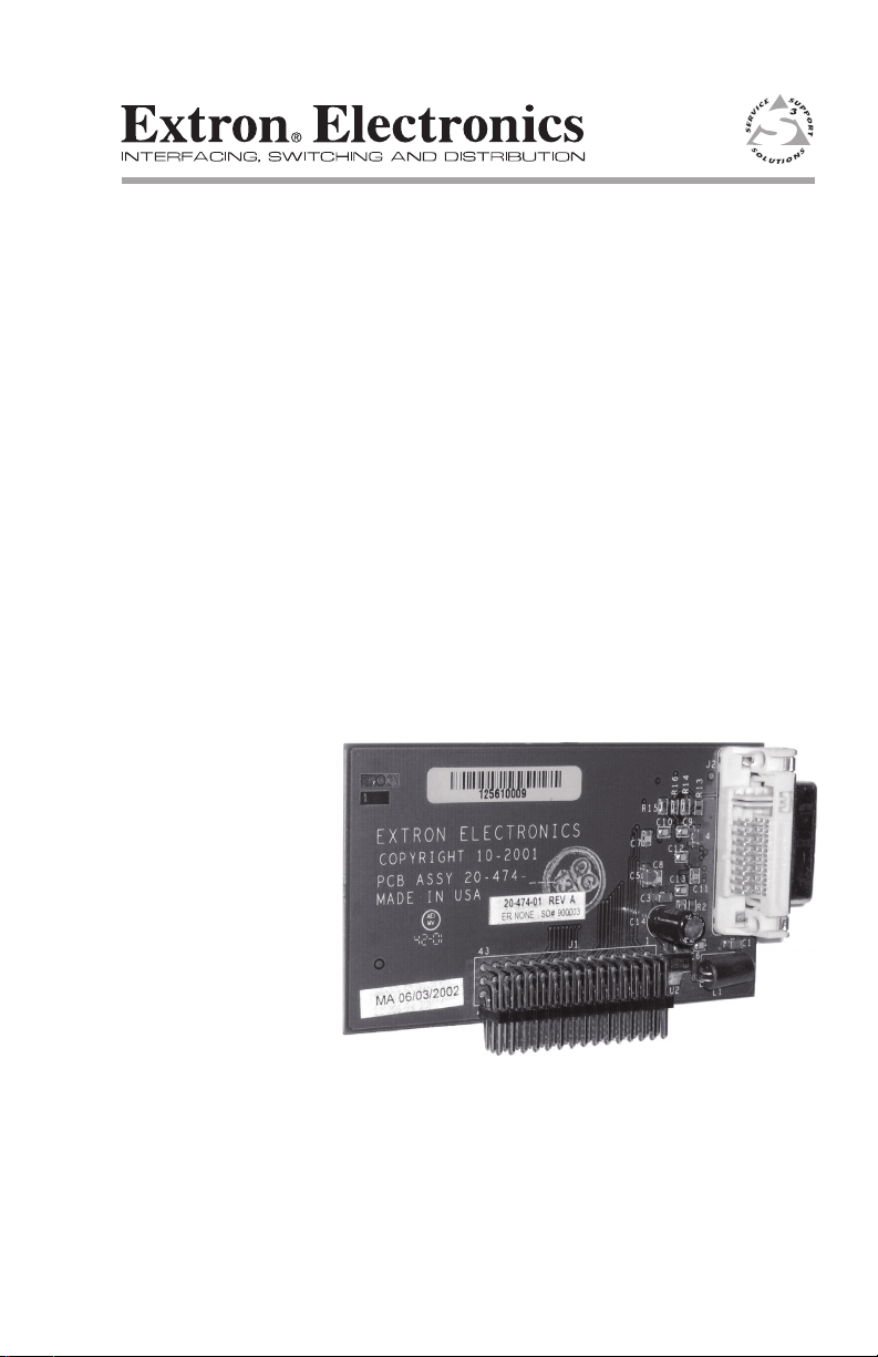
DVI Output Card
Digital Visual Interface Card for ISS 108/408 and ISM 482
68-761-01 Rev. B
01 09
Page 2

Installation
An optional digital visual interface (DVI) output card is available for
the ISS 108, ISS 408, and ISM 482. With the card installed, the switcher
outputs Program video simultaneously on the standard DVI connector
and Program Output BNC and 15-pin HD connectors.
Opening the Switcher
Extron recommends returning the switcher to Extron for service and
updates.
N The ISM 482 Switcher installation is shown. The ISS 108 and
ISS 408 installations are similar.
To install the optional DVI output card, the switcher case must be
removed.
Remove as follows:
1. Disconnect the AC power cord to remove power from the switcher.
W To prevent electric shock, always unplug the switcher from
the AC power source before opening the enclosure.
2. If the switcher is installed in a rack, disconnect all signal and
control cables and remove the switcher from the rack.
3. Remove the 16 screws from the switcher, 8 on the top and 4 on
each side of the cover (figure 1).
4. Remove the top two front panel screws.
5. Lift the top cover straight up approximately five inches for access
to the fan power cords.
C Do not touch any switches or other electronic components
inside the switcher. Doing so could damage the switcher.
Electrostatic discharge (ESD) can damage IC chips even
though it cannot be felt. A grounding wrist strap is
recommended.
6. Disconnect the two fan power cords from connectors J8 and J13 on
the main board.
7. Remove the top cover and set it aside.
DVI Output Card Installation
1
Page 3

Installation, cont’d
1
2 3 4
5
6
7
8
1
0
0
-
240
50/60 Hz
1.2A MAX.
R
1
G
B
H/HV
R
2
G
B
H/HV
R
3
G
B
H/HV
R
INPUTS
4
G
B
H/HV
R
5
G
B
H/HV
R
6
G
B
H/HV
R
7
G
B
H/HV
R
8
G
B
H/HV
B
H/HV
V
H/HV
V
Remove (16)
screws.
Remove top two
front panel screws.
Lift cover straight up.
Fan Connectors:
J8 and J13.
J8
J13
3
4
6
5
DVI card socket J14
Figure 1 — Removing the switcher cover
DVI Output Card Installation
2
Page 4

Installation, cont’d
DVI Output Card
Socket J14 on
Main Circuit Board
DVI Output Card
Connector Opening
Rear Panel
DVI Output Card Installation
Install the DVI output card in the switcher as follows:
W Changes to electronic components must be performed by
authorized service personnel only.
W To prevent electric shock, always unplug the switcher
from the AC power source before opening the enclosure.
1. Locate the DVI output card connector opening on the rear
panel and the DVI output card socket J14 on the left rear
portion of the main circuit board, as viewed from the front
(figure 2).
3
Figure 2 — DVI output card connector opening and
socket J14
DVI Output Card Installation
Page 5

Installation, cont’d
DVI Output Card
Mated to the
Main Board via
Socket J14
DVI Output Card
DVI Output Card
DVI Connector
2. If the rear panel DVI connector opening is covered, remove the
two screws that secure the cover to the back panel and remove
the cover.
3. Position the DVI card above J14 with the DVI connector facing
toward the rear of the switcher. Ensure the pins on the DVI
card properly align with the J14 socket to prevent bending.
4. Carefully insert the DVI board 45-pin connector into socket J14
on the main circuit board (figure 3).
DVI Output Card Installation
Figure 3 — Output DVI board installation
5. Secure the DVI card to the rear panel with the two screws
provided in the kit.
C Carefully inspect the pins to be certain all are properly seated
in the socket before proceeding. The board connector should
have all pins inserted the same depth.
4
Page 6

Extron USA - West
Headquarters
+800.633.9876
Inside USA / Canada Only
+1.714.491.1500
+1.714.491.1517 FAX
Extron USA - East
+800.633.9876
Inside USA / Canada Only
+1.919.863.1794
+1.919.863.1797 FAX
Extron Europe
+800.3987.6673
Inside Europe Only
+31.33.453.4040
+31.33.453.4050 FA X
Extron Asia
+800.7339.8766
Inside Asia Only
+65.6383.4400
+65.6383.4664 FAX
Extron Japan
+81.3.3511.7655
+81.3.3511.7656 FAX
Extron China
+400.883.1568
Inside China Only
+86.21.3760.1568
+86.21.3760.1566 FAX
Extron Middle East
+971.4.2991800
+971.4.2991880 FAX
Installation, cont’d
Closing the Switcher
1. Reconnect the two fan power cords to connectors J8 and J13 on the
main board. It does not matter which fan is connected to which
connector.
2. Replace the top cover on the switcher.
3. Fasten it with the screws that were removed in "Opening the
Switcher", step 3 and step 4.
4. Reinstall the switcher and reconnect all cables.
© 2009 Extron Electronics. All rights reserved.
 Loading...