

Page 1
Quick Start Guide
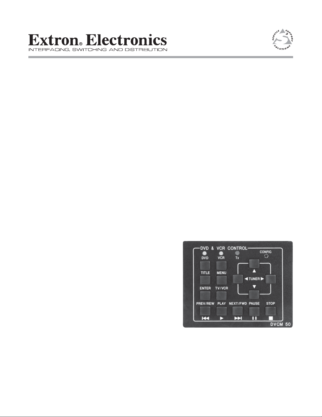
DVCM 50
DVD/VCR Control Module
68-1208-01 Rev. A
11 05
Page 2

Precautions
Safety Instructions • English
This symbol is intended to alert the user of important operating and maintenance
(servicing) instructions in the literature provided with the equipment.
This symbol is intended to alert the user of the presence of uninsulated dangerous
voltage within the product’s enclosure that may present a risk of electric shock.
Caution
Read Instructions • Read and understand all safety and operating instructions before using the equipment.
Retain Instructions • The safety instructions should be kept for future reference.
Follow Warnings • Follow all warnings and instructions marked on the equipment or in the user
information.
Avoid Attachments • Do not use tools or attachments that are not recommended by the equipment
manufacturer because they may be hazardous.
Consignes de Sécurité • Français
Ce symbole sert à avertir l’utilisateur que la documentation fournie avec le matériel
contient des instructions importantes concernant l’exploitation et la maintenance
(réparation).
Ce symbole sert à avertir l’utilisateur de la présence dans le boîtier de l’appareil
de tensions dangereuses non isolées posant des risques d’électrocution.
Attention
Lire les instructions• Prendre connaissance de toutes les consignes de sécurité et d’exploitation avant
d’utiliser le matériel.
Conserver les instructions• Ranger les consignes de sécurité afi n de pouvoir les consulter à l’avenir.
Respecter les avertissements • Observer tous les avertissements et consignes marqués sur le matériel ou
présentés dans la documentation utilisateur.
Eviter les pièces de fi xation • Ne pas utiliser de pièces de fi xation ni d’outils non recommandés par le
fabricant du matériel car cela risquerait de poser certains dangers.
Sicherheitsanleitungen • Deutsch
Dieses Symbol soll dem Benutzer in der im Lieferumfang enthaltenen
Dokumentation besonders wichtige Hinweise zur Bedienung und Wartung
(Instandhaltung) geben.
Dieses Symbol soll den Benutzer darauf aufmerksam machen, daß im Inneren des
Gehäuses dieses Produktes gefährliche Spannungen, die nicht isoliert sind und
die einen elektrischen Schock verursachen können, herrschen.
Achtung
Lesen der Anleitungen • Bevor Sie das Gerät zum ersten Mal verwenden, sollten Sie alle Sicherheits-und
Bedienungsanleitungen genau durchlesen und verstehen.
Aufbewahren der Anleitungen • Die Hinweise zur elektrischen Sicherheit des Produktes sollten Sie
aufbewahren, damit Sie im Bedarfsfall darauf zurückgreifen können.
Befolgen der Warnhinweise • Befolgen Sie alle Warnhinweise und Anleitungen auf dem Gerät oder in der
Benutzerdokumentation.
Keine Zusatzgeräte • Verwenden Sie keine Werkzeuge oder Zusatzgeräte, die nicht ausdrücklich vom
Hersteller empfohlen wurden, da diese eine Gefahrenquelle darstellen können.
Warning
Power sources • This equipment should be operated only from the power source indicated on the product. This
equipment is intended to be used with a main power system with a grounded (neutral) conductor. The
third (grounding) pin is a safety feature, do not attempt to bypass or disable it.
Power disconnection • To remove power from the equipment safely, remove all power cords from the rear of
the equipment, or the desktop power module (if detachable), or from the power source receptacle (wall
plug).
Power cord protection • Power cords should be routed so that they are not likely to be stepped on or pinched by
items placed upon or against them.
Servicing • Refer all servicing to qualifi ed service personnel. There are no user-serviceable parts inside. To
prevent the risk of shock, do not attempt to service this equipment yourself because opening or removing
covers may expose you to dangerous voltage or other hazards.
Slots and openings • If the equipment has slots or holes in the enclosure, these are provided to prevent
overheating of sensitive components inside. These openings must never be blocked by other objects.
Lithium battery • There is a danger of explosion if battery is incorrectly replaced. Replace it only with the
same or equivalent type recommended by the manufacturer. Dispose of used batteries according to the
manufacturer’s instructions.
Avertissement
Alimentations• Ne faire fonctionner ce matériel qu’avec la source d’alimentation indiquée sur l’appareil. Ce
matériel doit être utilisé avec une alimentation principale comportant un fi l de terre (neutre). Le troisième
contact (de mise à la terre) constitue un dispositif de sécurité : n’essayez pas de la contourner ni de la
désactiver.
Déconnexion de l’alimentation• Pour mettre le matériel hors tension sans danger, déconnectez tous les cordons
d’alimentation de l’arrière de l’appareil ou du module d’alimentation de bureau (s’il est amovible) ou
encore de la prise secteur.
Protection du cordon d’alimentation • Acheminer les cordons d’alimentation de manière à ce que personne ne
risque de marcher dessus et à ce qu’ils ne soient pas écrasés ou pincés par des objets.
Réparation-maintenance • Faire exécuter toutes les interventions de réparation-maintenance par un technicien
qualifi é. Aucun des éléments internes ne peut être réparé par l’utilisateur. Afi n d’éviter tout danger
d’électrocution, l’utilisateur ne doit pas essayer de procéder lui-même à ces opérations car l’ouverture ou le
retrait des couvercles risquent de l’exposer à de hautes tensions et autres dangers.
Fentes et orifi ces • Si le boîtier de l’appareil comporte des fentes ou des orifi ces, ceux-ci servent à empêcher
les composants internes sensibles de surchauffer. Ces ouvertures ne doivent jamais être bloquées par des
objets.
Lithium Batterie • Il a danger d’explosion s’ll y a remplacment incorrect de la batterie. Remplacer uniquement
avec une batterie du meme type ou d’un ype equivalent recommande par le constructeur. Mettre au reut les
batteries usagees conformement aux instructions du fabricant.
Vorsicht
Stromquellen • Dieses Gerät sollte nur über die auf dem Produkt angegebene Stromquelle betrieben werden.
Dieses Gerät wurde für eine Verwendung mit einer Hauptstromleitung mit einem geerdeten (neutralen)
Leiter konzipiert. Der dritte Kontakt ist für einen Erdanschluß, und stellt eine Sicherheitsfunktion dar. Diese
sollte nicht umgangen oder außer Betrieb gesetzt werden.
Stromunterbrechung • Um das Gerät auf sichere Weise vom Netz zu trennen, sollten Sie alle Netzkabel
aus der Rückseite des Gerätes, aus der externen Stomversorgung (falls dies möglich ist) oder aus der
Wandsteckdose ziehen.
Schutz des Netzkabels • Netzkabel sollten stets so verlegt werden, daß sie nicht im Weg liegen und niemand
darauf treten kann oder Objekte darauf- oder unmittelbar dagegengestellt werden können.
Wartung • Alle Wartungsmaßnahmen sollten nur von qualifi ziertem Servicepersonal durchgeführt werden.
Die internen Komponenten des Gerätes sind wartungsfrei. Zur Vermeidung eines elektrischen Schocks
versuchen Sie in keinem Fall, dieses Gerät selbst öffnen, da beim Entfernen der Abdeckungen die Gefahr
eines elektrischen Schlags und/oder andere Gefahren bestehen.
Schlitze und Öffnungen • Wenn das Gerät Schlitze oder Löcher im Gehäuse aufweist, dienen diese zur
Vermeidung einer Überhitzung der empfi ndlichen Teile im Inneren. Diese Öffnungen dürfen niemals von
anderen Objekten blockiert werden.
Litium-Batterie • Explosionsgefahr, falls die Batterie nicht richtig ersetzt wird. Ersetzen Sie verbrauchte
Batterien nur durch den gleichen oder einen vergleichbaren Batterietyp, der auch vom Hersteller
empfohlen wird. Entsorgen Sie verbrauchte Batterien bitte gemäß den Herstelleranweisungen.
Instrucciones de seguridad • Español
Este símbolo se utiliza para advertir al usuario sobre instrucciones importantes
de operación y mantenimiento (o cambio de partes) que se desean destacar en el
contenido de la documentación suministrada con los equipos.
Este símbolo se utiliza para advertir al usuario sobre la presencia de elementos con
voltaje peligroso sin protección aislante, que puedan encontrarse dentro de la caja
o alojamiento del producto, y que puedan representar riesgo de electrocución.
Precaucion
Leer las instrucciones • Leer y analizar todas las instrucciones de operación y seguridad, antes de usar el
equipo.
Conservar las instrucciones • Conservar las instrucciones de seguridad para futura consulta.
Obedecer las advertencias • Todas las advertencias e instrucciones marcadas en el equipo o en la
documentación del usuario, deben ser obedecidas.
Evitar el uso de accesorios • No usar herramientas o accesorios que no sean especifi camente recomendados
por el fabricante, ya que podrian implicar riesgos.
安全须知 • 中文
这个符号提 示用户该设备用户手册中有重要的操 作和维护说明。
这个符号警告用户该设备机壳内有暴露的危险电压,有触电危险。
注意
阅读说明书 • 用户使用该设备前必须阅读并理解所有安全和使用说明。
保存说明书 • 用户应保存 安全说明书以备将来使用。
遵守警告 • 用户应遵守产品和用户指南上的所有安 全和操作说明。
避免追加 • 不要使用该产品厂商没有推荐的工具或追加设备,以避免危险。
Advertencia
Alimentación eléctrica • Este equipo debe conectarse únicamente a la fuente/tipo de alimentación eléctrica
indicada en el mismo. La alimentación eléctrica de este equipo debe provenir de un sistema de distribución
general con conductor neutro a tierra. La tercera pata (puesta a tierra) es una medida de seguridad, no
puentearia ni eliminaria.
Desconexión de alimentación eléctrica • Para desconectar con seguridad la acometida de alimentación eléctrica
al equipo, desenchufar todos los cables de alimentación en el panel trasero del equipo, o desenchufar el
módulo de alimentación (si fuera independiente), o desenchufar el cable del receptáculo de la pared.
Protección del cables de alimentación • Los cables de alimentación eléctrica se deben instalar en lugares donde
no sean pisados ni apretados por objetos que se puedan apoyar sobre ellos.
Reparaciones/mantenimiento • Solicitar siempre los servicios técnicos de personal califi cado. En el interior no
hay partes a las que el usuario deba acceder. Para evitar riesgo de electrocución, no intentar personalmente
la reparación/mantenimiento de este equipo, ya que al abrir o extraer las tapas puede quedar expuesto a
voltajes peligrosos u otros riesgos.
Ranuras y aberturas • Si el equipo posee ranuras o orifi cios en su caja/alojamiento, es para evitar el
sobrecalientamiento de componentes internos sensibles. Estas aberturas nunca se deben obstruir con otros
objetos.
Batería de litio • Existe riesgo de explosión si esta batería se coloca en la posición incorrecta. Cambiar esta
batería únicamente con el mismo tipo (o su equivalente) recomendado por el fabricante. Desachar las
baterías usadas siguiendo las instrucciones del fabricante.
警告
电源 • 该设备只能使用产品上标明的电源。 设备必须使用有地线的供电系统供电。 第三条线
(地线)是 安全设 施,不能不用或跳过 。
拔掉电源 • 为安全地从设备拔掉电源,请拔掉所有设备后或桌面电源的电源线,或任何接到市
电系统的电源线。
电源线保护 • 妥善布线, 避免被踩踏,或重物挤压。
维护 • 所有维修必须由认证的维修人员进行。 设备内部没有用户可以更换的零件。为避免出
现触电危险不要自己试图打开设备盖子维修该设备。
通风孔 • 有些设备机壳上有通风 槽或孔,它们是用来防止机内敏感元件过热。 不要用任 何东
西挡住通风 孔。
锂电池 • 不正确的更换电池会有爆炸的危险。必须使用与厂家推荐的相同或 相近型号的电池。
按照生产厂的建议处理废弃电池。
Page 3
DVCM 50 Control Module Quick Start Guide
The DVCM 50 DVD/VCR Control Module is a four-space Architectural Adapter
Plate (AAP) module that is used for controlling DVDs and VCRs. It can be used
with an MLC 52 or MLC 104 MediaLink Controller, or as a standalone control
module, sending IR signals directly to the DVD or VCR. The DVCM 50 can be
confi gured by the following methods:
• IR learning from a DVD or VCR remote control
• IR data transfer (beaming) from another DVCM that has been confi gured
• Using IR drivers via the Extron’s Windows
program
The DVCM 50 DVD/VCR Control Module Quick Start Guide is designed to give you
an overview of what you need to do to set up and operate your DVCM 50, and to
help you quickly get started using it. For more details regarding the installation,
operation, and confi guration of the DVCM 50, refer to the DVCM 50 User’s Manual,
provided on CD with your DVCM.
Hardware overview
The following sections describe the DVCM 50 components located on the front and
rear panels of the control module.
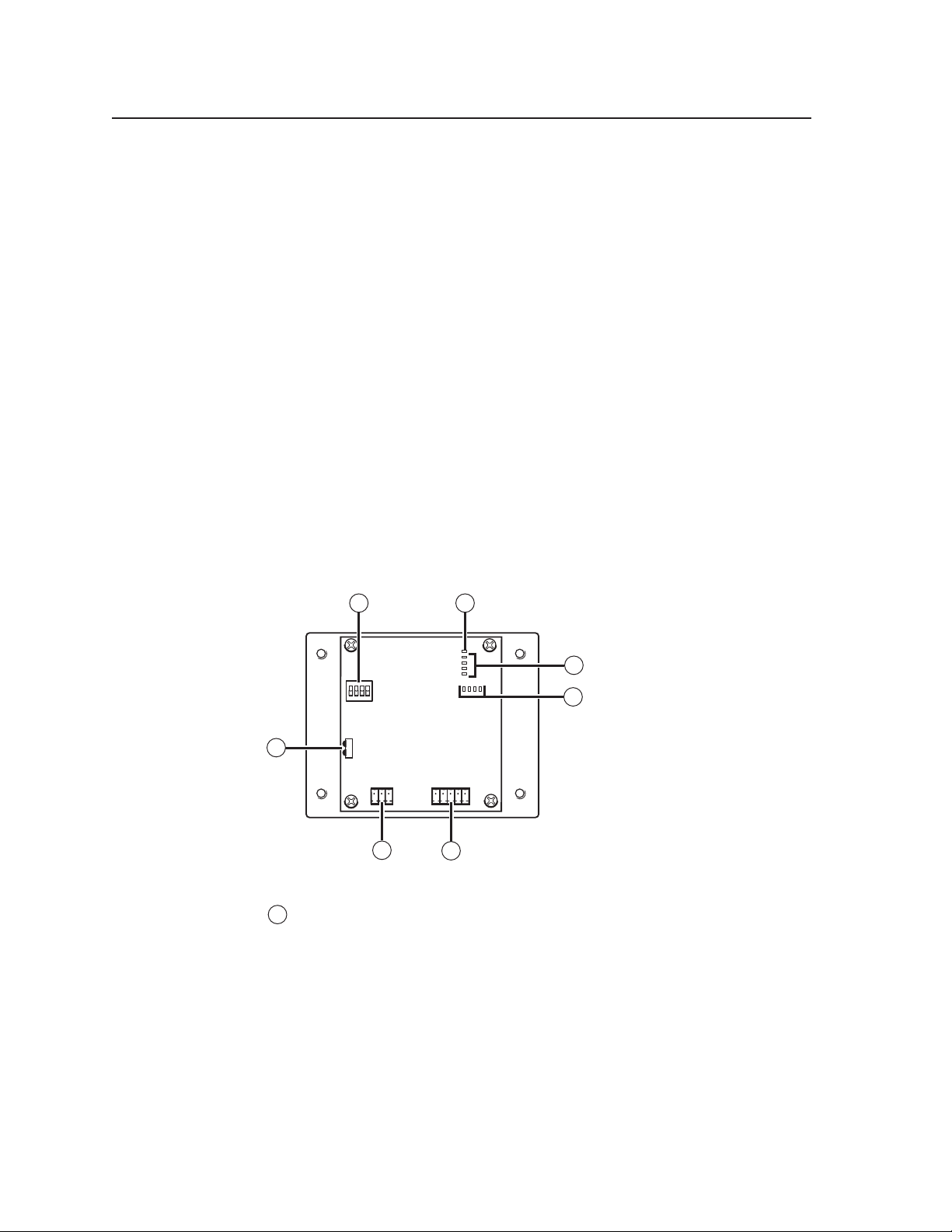
Rear panel features
®
-based confi guration software
PRELIMINARY
1
ON
1
2 3 4
2
E
4
3
2
1
8 4 2 1
3
4
7
IR OUT
GND
IR IN
GND
GND
Rx
Tx
6
+ 12V
5
DVCM 50 rear panel
1
Confi guration switches — These DIP switches place the DVCM in IR
learning mode or data transfer mode.
• Switch 1: Enables IR learning.
• Switch 2: Enables data transfer, such as cloning the DVCM’s
confi guration onto another DVCM 50.
• Switch 3: When this switch is placed in the On (up) position, commands
are issued only once when a button is pressed and held. If the switch
is set to Off (down), commands are issued repeatedly for as long as the
button is held.
Switch 4: Enables MLC 104 input mapping.•
DVCM 50 • Quick Start Guide
1
Page 4
DVCM 50 Quick Start Guide, cont’d
2
Enable Macro LED — The LED located immediately above the four green IR
LEDs is labeled E, for Enable Macro. This LED lights orange when you place
a button in macro mode. (See Setting up button macros, later in this guide.)
3
IR learning indicator LEDs — Each front panel button has four memory
blocks, which can be programmed with up to four IR commands. The IR
learning indicator LEDs indicate the following:
• Which of the four memory blocks contains a command
• Which of the four memory blocks is ready to be programmed or
confi gured.
• The IR learning status of the control module
4
Button Indicator LEDs — These LEDs light in various patterns to indicate
which button on the front panel has been pressed when the DVCM is in
learning mode (confi guration switch #1 is in the On (up) position).
5
Control and power connector — This fi ve-pole, 3.5 mm captive screw
connector is used for IR control of the DVD and VCR, and for DC power. (See
Installing the DVCM 50, later in this guide, for information on how to connect
supported devices to this connector.)
6
MLC 104 communication port — This 3.5 mm, 3-pole captive screw
connector, located near the lower-left corner of the rear panel, is used
for connecting to the MLC 104 (special application). When the DVCM is
operating in standalone mode, this port is not used. (Refer to your DVCM
50 User’s Manual, chapter 4, for information on using the MLC 104 with the
DVCM 50.)
PRELIMINARYPRELIMINARYPRELIMINARY
7
IR Learner/Transmitter LEDs — These sensors allow for IR control of
the DVCM and for IR learning. The two LEDs (one for transmitting, one
for receiving) send and receive IR signals, enabling the DVCM to learn
commands and clone confi gurations from another DVCM. (See Confi guring
using IR data transfer, later in this guide, for instructions on setting up for IR
data transfer.)
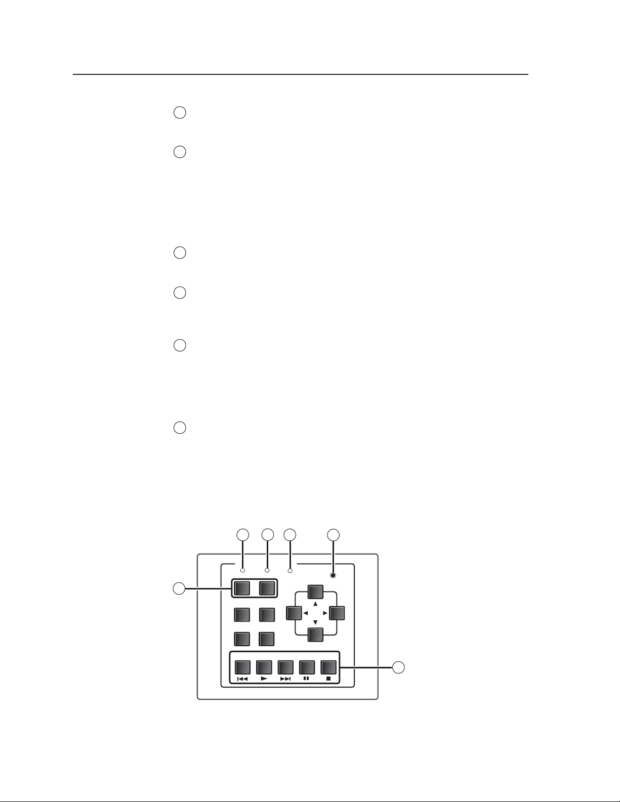
Front panel features
3
2
DVD & VCR CONTROL
DVD VCR
1
TITLE MENU
TV/VCR
ENTER
PLAY NEXT/FWD PAUSE STOP
PREV/REW
DVCM 50 front panel
4
Tx
5
CONFIG
TUNER
6
DVCM 50
2
DVCM 50 • Quick Start Guide
Page 5
1
DVD and VCR (mode selection) buttons — Use these buttons to switch the
DVCM 50 operating mode between DVD and VCR. After one of these buttons
is pressed, the DVCM buttons issue commands that control only the device
with which the button is labeled (DVD or VCR).
The DVD and VCR buttons each have four memory blocks that can be
programmed with commands. In addition, pressing either mode selection
button always causes the DVCM to switch to the mode of the button that was
pressed.
2
DVD indicator LED — This LED glows amber when the DVCM is in DVD
mode.
3
VCR indicator LED — This LED glows amber when the DVCM is in VCR
mode.
4
Tx (Transmission) LED — This green LED blinks while the DVCM is
transmitting IR commands. It also blinks when any programmed front panel
button is pressed. If a button is held down, the Tx LED continues to blink
until the button is released.
If a button that was not programmed is pressed, the Tx LED does not blink.
5
Confi guration port — This port is used for system confi guration and for
loading control fi les into the DVCM. Commands can be received through
this port from the PC, using Simple Instruction Set (SIS
Windows-based confi guration software. See Confi guring using the Windows-
based confi guration software, later in this guide, for information about this port
and the cable that connects to it.
™
) commands or the
Refer to your DVCM 50 User’s Manual, chapter 5, for details about using the
software to confi gure the system.
6
DVD and VCR control buttons — These buttons may be used to control a DVD
player, a VCR, or a combination DVD/VCR. The buttons can be programmed
via IR learning, data transfer, or the Windows-based confi guration software to
perform the functions for which they are labeled. Each of these buttons has eight
memory blocks (four available in DVD mode and four for VCR mode), which can
be programmed with commands.
Other buttons on the front panel
The remaining front panel buttons are typically programmed to initiate the functions
with which they are labeled. Except for
available in either DVD mode or VCR mode; they do not function in both modes. Each
of these buttons has four memory blocks that can be programmed with commands.
The buttons on the DVCM 50 front panel are labeled with the names of functions
that are typically found on a DVD player or a VCR and their remote controls.
However, if desired, you can program these buttons with different functions.
TV/VCR — (VCR mode only) Program this button with the IR command that
causes the VCR to switch between operating as a TV tuner and operating as
a VCR. This button can be programmed and can issue IR commands only in
VCR mode.
Title — (DVD mode only) Program this button with the IR command that displays
the main menu on the display device screen. This button can be programmed
and can issue IR commands only in DVD mode.
Enter — (DVD mode only) Program this button with the IR command that selects
items from the DVD’s on-screen menu. This button can be programmed and
can issue IR commands only in DVD mode.
Tu n e r S and T, the buttons listed below are
PRELIMINARY
DVCM 50 • Quick Start Guide
3
Page 6
DVCM 50 Quick Start Guide, cont’d
Menu — (DVD mode only) Program this button with the IR command that
displays the DVD menu on your display device. This button can be
programmed and can issue IR commands only in DVD mode.
Tu n e r W and X — (DVD mode only) Program these buttons with the IR command
that moves the cursor right or left on the screen in order to select menu
items or function icons. These buttons can be programmed and can issue IR
commands only in DVD mode.
Tu n e r S and T —
VCR mode: Switches TV channels up and down when the VCR is in tuner
mode.
DVD mode: When programmed, moves the cursor up and down between
menu items or other items on the screen.
Installing the DVCM 50
Step 1
Mount the DVCM 50 to a device faceplate or an AAP wallplate that
accommodates four 1-unit AAPs. (See the user documentation included with your
faceplate or wallplate for instructions on mounting the DVCM to it.)
PRELIMINARYPRELIMINARY
Step 2
Attach cables to the control connector on the DVCM 50 rear panel.
IR out
(IR)
IR in
(+12V)
+12V
E D C B A
Pinout guide for the DVCM 50 control connector
The ports in the control connector, from left to right, have the following functions:
IR Out — Used for connecting an IR emitter to issue IR commands for DVD
and VCR control. Up to two emitters can be wired to this port. There is a
maximum of 100’ wiring distance from the port to the emitter.
GND
IR In — Used for connecting an optional IR Link or IRL 20, so that the IR 452
GND
+12V — Power input for the DVCM (12 VDC)
— Ground for IR In and IR Out
remote can control the DVCM.
— Ground for the +12 VDC power
4
DVCM 50 • Quick Start Guide
Page 7

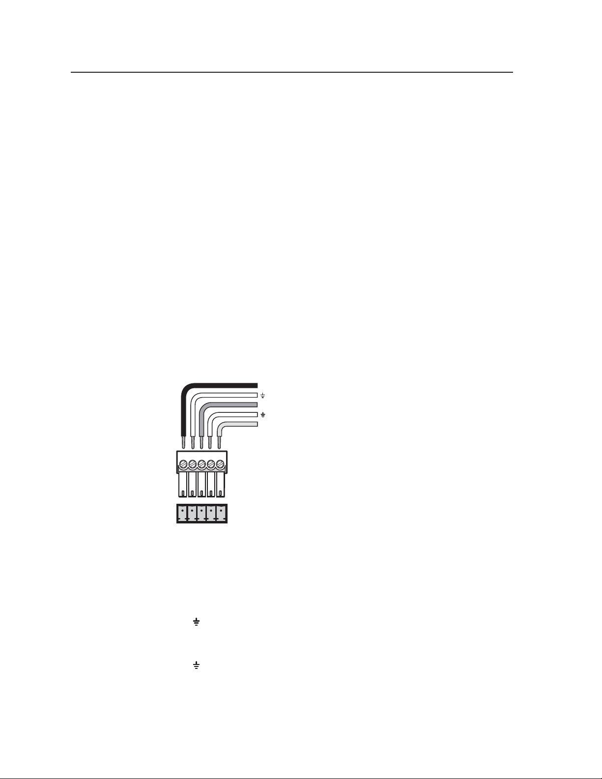
a. Wire the IR control port. To control the DVD or VCR via IR, connect Extron
IR Emitters to the IR Out port of the DVCM control connector. Up to two IR
emitters can be connected via this connector at one time. Wire the connector
as shown in the following illustration.
For the IR Emitter only
Wiring for IR control
b. (Optional) Wire the IR Link or IRL 20 to the IR In port, to provide IR remote
c. (Optional) Wire the power connector. Connect the optional external 12
(If you will be using the DVCM with an MLC 104, through which power will
Step 3
(Optional) Attach cables to the IR Link, the IR Emitter, and/or the IRL 20.
Step 4
Connect power cords and turn on all the devices, including the DVCM.
IR
Emitter
Connect this end to the IR control
window of the DVD or VCR .
Connect up to
2 IR Emitters
(max.).
E D C B A
IR
DVCM 50
IR control
port
Modulated IR
E
D
Ground
100 feet (33.5 m) maximum
White striped wire only
control after the DVCM is mounted. Refer to Wiring for IR remote control in
chapter 2 of your DVCM 50 User’s Manual for wiring instructions.
VDC power supply to the power port. Refer to Wiring the Power connector in
chapter 2 of the DVCM 50 User’s Manual for instructions.
be supplied, you can skip this step.)
PRELIMINARY
Step 5
Confi gure the controller using one of the following methods:
IR learning (See Confi guring using IR learning, later in this guide.)
•
IR Data Transfer (See Confi guring using IR data transfer, later in this guide.)
•
•
Windows
®
-based confi guration software (See chapter 5, Software-based
Confi guration and Control, in your DVCM 50 User’s Manual, for the procedures.)
Step 6
Test the system. Press the DVCM’s buttons, and observe the VCR and/or DVD
player’s responses.
Step 7
(Optional) Mount the AAP faceplate or wallplate containing the DVCM 50 to a
wall or furniture. (Refer to the user documentation provided with the faceplate or
wallplate for mounting procedures.)
DVCM 50 • Quick Start Guide
5
Page 8

DVCM 50 Quick Start Guide, cont’d
Confi guring the DVCM 50
The DVCM 50 can be programmed using the following methods:
• IR learning from your DVD or VCR remote control
• IR data transfer from another DVCM 50 that has been confi gured previously
• Using DVD/VCR drivers with the MLC 52/DVCM 50 Windows
confi guration software.
Confi guring using IR learning
You can confi gure the DVCM 50 by using IR learning, which does not require
confi guration software. By this method, you can program the functions on your
DVD and/or VCR’s remote control into the buttons on the DVCM front panel.
To program the DVCM via IR learning, follow these steps:
Step 1
Apply power to the DVCM.
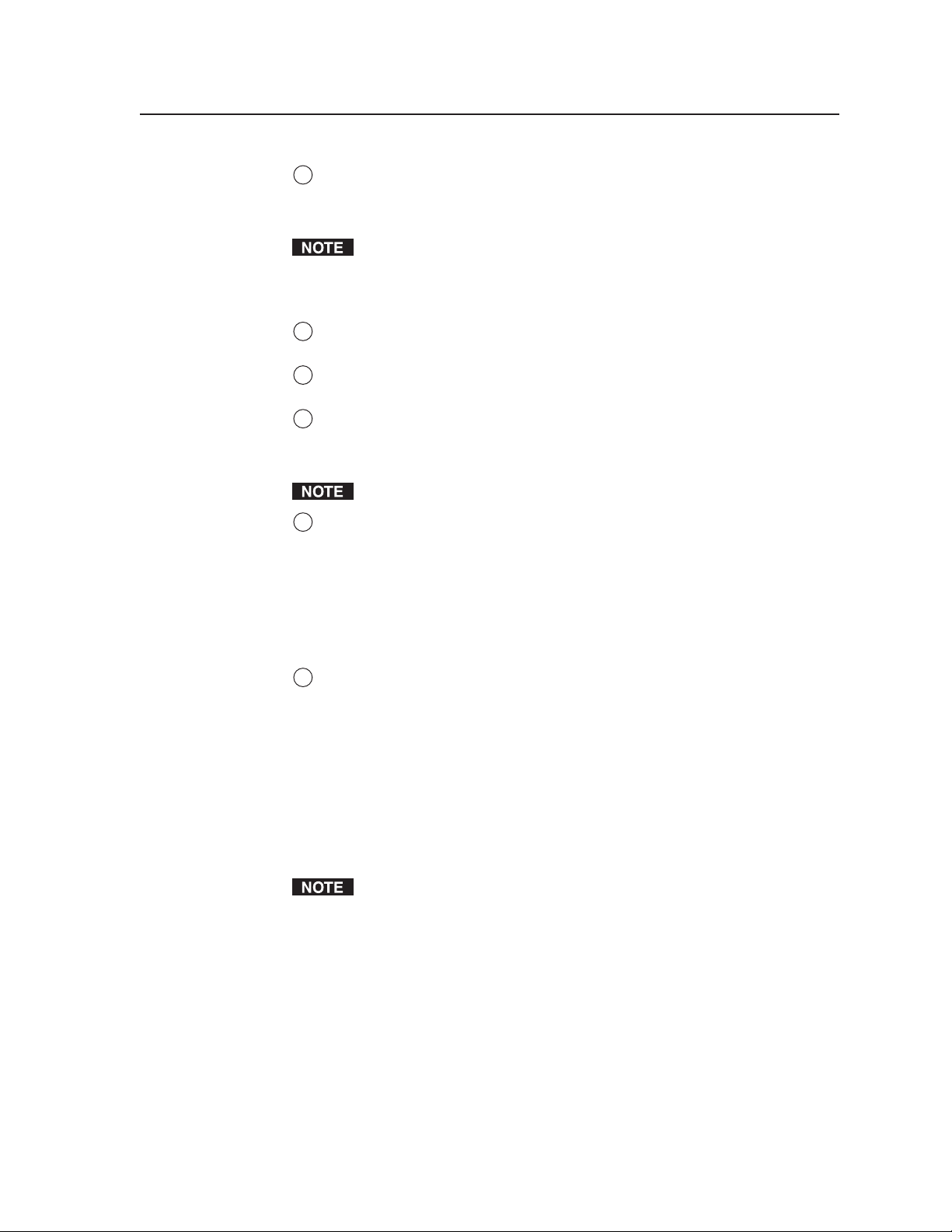
Step 2
Set confi guration switch #1 on the rear panel to On, as shown at
right. All other switches should be Off.
®
-based
1ON234
PRELIMINARYPRELIMINARY
Step 3
Press the DVD or VCR button on the front panel to select the mode in which
the button will be programmed. The LED lights above the button you pressed,
indicating that the front panel buttons will be programmed in that mode.
Step 4
Press the button on the front panel that will store the IR code that you want the
DVCM to learn. The following takes place on the DVCM rear panel:
• The orange button indicator LED(s) light and remain lit to show which button
was pressed. The diagram on the next page shows which LEDs are lit when
each button is pressed.
6
DVCM 50 • Quick Start Guide
Page 9

Legend
OFF
No Buttons
ON
DVD
VCR
UP
TITLE
MENU
LEFT
RIGHT
ENTER
TV/VCR
DOWN
REW
PLAY
FWD
PAUSE
STOP
Button press indicator LEDs
The following buttons cannot be programmed in VCR mode. The DVCM
must be in DVD mode to program them.
Title
Menu
Enter
Right
X (Tuner)
Left W (Tuner)
The TV/VCR button cannot be programmed in DVD mode. It can be
programmed only in VCR mode.
If you press a button that does not function in the current mode, the button’s
orange indicator LED(s) blink three times, indicating that the button cannot be
programmed.
• The IR learning LED that indicates the button memory block currently
available for programming begins to blink. (See IR learning indicators in the
chapter 2 of the DVCM 50 User’s Manual for further information.) The LEDs
located below the blinking LED light steadily, indicating that they already
contain commands.
PRELIMINARY
DVCM 50 • Quick Start Guide
7
Page 10

DVCM 50 Quick Start Guide, cont’d
Step 5
LED Off
LED Blinking
LED On
E
4
3
2
1
Command 1 ready to
be learned
E
4
3
2
1
Command 2 ready
to be learned
Command 1 learned
E
4
3
2
1
Command 3 ready
to be learned.
Command 2 learned
Command 1 learned
E
4
3
2
1
Command 4 ready
to be learned
Command 3 learned
Command 2 learned
Command 1 learned
Activation of learning indicator LEDs during button programming
Within 5 seconds, point the DVD or VCR remote control at the IR learning
sensors on the rear panel, and press the remote control button whose function
you want the selected DVCM button to learn.
•
If the IR command is learned successfully, the IR learning indicator LEDs blink
in rapid progression from the top to the bottom, then back to the top.
If the IR code that you entered results in an error, the buttons blink randomly.
•
For repeating command codes, such as those that increment/decrement a
function (for example, scanning up and down through the channels on a VCR
that is in TV mode), hold the button on the DVD or VCR remote control for at
least 3 seconds.
PRELIMINARYPRELIMINARY
Step 6
Do one of the following:
•
If you want to add another command to the same button, press the same
DVCM button again. The next Learning LED on the rear panel begins
fl ashing. Repeat step 5 to add the desired command. (You can program up to
four commands on one button.)
•
If you want to program commands onto another DVCM button, repeat steps 3
through 5 for the next button that you want to program.
Step 7
When fi nished programming buttons, set confi guration switch #1 on the rear
panel to Off. Verify that the commands you entered have been learned by pressing
the buttons that you programmed and observing the actions of the DVD/VCR.
It may be helpful to program all DVD functions fi rst, then the VCR functions.
Programming the DVD and VCR mode buttons
The procedure for programming commands onto the DVD and VCR buttons is
the same as the procedure for programming the other buttons (see the previous
section), except that you skip step 4. Pressing either of these buttons once
accomplishes the following:
•
Places the DVCM in button’s mode (DVD or VCR, depending on which button
was pressed).
Selects the button’s next available memory block for programming.
•
8
DVCM 50 • Quick Start Guide
Page 11

Setting up button macros
DVCM 50 buttons function in either toggle mode or macro mode. By default, the
buttons are in toggle mode, which means that each press of the button initiates one
of the commands saved to the button (each button can store up to four commands).
In macro mode, a single press of a button issues all the commands (up to four) that
have been programmed on that button, in the order they were programmed, at
1.5-second intervals.
To put a button in macro mode, follow these steps:
1. Ensure that power is applied to the DVCM 50.
2. Set confi guration switch #1 on the rear panel to On (up).
3. Program the buttons with the desired commands. See Confi guring using IR
data transfer, later in this guide, or Confi guring using IR learning, earlier in this
section, for programming procedures.
4. To put the button in macro mode, press and hold it for 3 seconds. The orange
LED above the learning indicator LEDs, labeled “E” on the back panel, fl ashes
rapidly fi ve times, then turns off, indicating that the button is now confi gured
for macro mode. Release the button.
The next time that the button is pressed while confi guration switch #1 is in
the On (up) position, the orange E LED lights, indicating that the button is in
macro mode.
5. Set confi guration switch #1 to Off (down). Verify that the commands
have been properly learned by pressing the button you programmed. The
commands should be issued in succession at 1.5-second intervals.
Taking a button out of macro mode
To take a button out of macro mode, follow these steps:
1. Place confi guration switch #1 on the rear panel in the On (up) position.
2. Press and hold the button that is in macro mode for 3 seconds. The orange E
LED blinks three times, then turns off.
3. Press the button again to confi rm that the orange E LED has turned off,
indicating the button is no longer in macro mode.
4. Set Confi guration switch #1 to Off (down).
Commands that have been programmed on the button are not erased when the
button is taken out of macro mode.
Removing commands from a button
If you want to delete a command that has been programmed onto a button, you
must remove all the commands programmed to that button. Follow these steps:
1. While the DVCM 50 is powered on, set confi guration switch #1 to On (up).
2. Press the DVD or VCR button to place the DVCM in the mode in which you
want the commands to be erased.
3. Press the button for which you want to delete commands, then within
2 seconds press the button again. The IR learning LEDs turn off.
Example: If you want to erase the DVD player’s Play function from its Play
button, fi rst press the DVD button to ensure that the DVCM is in DVD mode.
Then, erase the Play function (and all other functions) from the Play button by
pressing it twice within 2 seconds.
PRELIMINARY
DVCM 50 • Quick Start Guide
9
Page 12

DVCM 50 Quick Start Guide, cont’d
4. Verify that the button’s commands were erased by pressing the button again.
If the commands have been erased, only LED #1 (the bottom LED) blinks; and
the other LEDs are off.
5. Repeat steps 1 through 3 for any additional buttons that you want to erase.
When fi nished, place switch #1 in the Off position (down).
To erase the commands from the DVD or the VCR button, press the button
twice: the fi rst time to switch to the desired mode; the second time to erase the
commands.
Confi guring using IR data transfer
You can also confi gure your DVCM 50 by transferring button confi guration data to
it from another confi gured DVCM 50 via the two IR LEDs on the back panels of the
DVCMs. With this method, you replicate (clone) the other DVCM’s confi guration
on your own unit without the use of software or cables.
To transmit confi guration data via IR, both the transferring and the receiving
DVCMs must be free of the wall, electrical box, or furniture. The DVCM that is
already confi gured must be powered by an external power supply, or by a power
supply shared with the unit that will be confi gured.
Step 1
Ensure that all confi guration switches are set to Off (down) on both the
transmitting and the receiving units.
PRELIMINARYPRELIMINARY
Step 2
Step 3
Step 4
Apply power to both units.
Align the two units so that the IR Transmit and Receive LEDs of both DVCMs
are facing each other, and between 1 and 2 inches apart.
On the DVCM that will receive the data, set confi guration switch #2 to On (up),
and all others to Off (down). (See the illustration below.) Leave all switches on the
transmitting unit (the donor unit) set to Off (down).
IR OUT
ON
2 3 4
1
Rx
Tx
GND
2 3 4
E
4
3
2
IR OUT
ON
GND
IR IN
1
8 4 2 1
GND
+ 12V
ON
1
2 3 4
1”- 2” apart
1
ON
GND
Rx
Tx
Receiving DVCM 50
Switch #2 on
1
2 3 4
Transmitting DVCM 50
All switches off
GND
IR IN
GND
+ 12V
8 4 2 1
1
2
3
4
E
10
Setting up transmitting and receiving units for IR data transfer
DVCM 50 • Quick Start Guide
Page 13

The data transfer begins when the receiving unit detects the transmitting unit,
and the process takes 15 to 20 seconds to complete. (It may take longer if the
transmitting unit has multiple commands programmed on each button.)
The button indicator LEDs on the rear panel act as data transfer progress
indicators. While data is being transferred, these LEDs on both DVCMs light to
indicate the amount of data that has been transferred.
After approximately 25% of the data has been transferred, the fi rst LED on
the right lights and remains lit. After another 50% has been transferred, the
second LED from the right lights. After 75% of the data is transferred, the
third LED from the right lights, and when the transfer is complete, all four
LEDS are lit.
The table below shows how each 25% increment of transferred data is shown
by the button indicator LEDs.
8 4 2 1
0% – All LEDs off
DVCM 50 (Rear Panel)
8 4 2 1
25%
8 4 2 1
50%
Button Indicator LEDs
8 4 2 1
75%
8 4 2 1
100% – All LEDs on
E
4
3
2
1
8421
Button indicator LEDs indicating percentage of data transferred
When the transfer is complete, all the button indicator LEDs remain lit.
Proceed to step 5.
If the transmission is interrupted (for example, the two units become
separated so that the IR LEDs are no longer in direct line of sight of each
other), and the conditions necessary for transfer are then restored, the two
units restart the transfer process.
Step 5
When data transfer is complete, do either of the following:
If fi nished confi guring, return confi guration switch #2 on the receiving
•
DVCM to the Off position. Press any button on both units to return them
to the state they were in before the transfer. Reinitialize the receiving unit by
pressing any of its front panel buttons.
If you want to repeat the transfer process to confi gure another DVCM 50,
•
repeat steps 3 and 4 for the unit that is to be confi gured. Press any button on
the transmitting unit to restart the transfer process.
PRELIMINARY PRELIMINARY
DVCM 50 • Quick Start Guide
11
Page 14

DVCM 50 Quick Start Guide, cont’d
Confi guring using the Windows-based confi guration software
The DVCM 50 can be remotely confi gured via a host computer connected to the
front panel confi guration port. Through this port, you can program the DVCM’s
buttons with commands by using the Windows-based confi guration software
(DVCM 50/DVCM 50 Control Program). The optional 9-pin D to 2.5 mm stereo
mini TRS RS-232 cable (part #70-335-01) can be used for this connection.
The cable has the following pin assignments:
PRELIMINARY
6 feet
(1.8 m)
To Front Panel
Config Port
DVCM 50
DVD & VCR CONTROL
DVD VCR
TITLE MENU
TV/VCR
ENTER
PLAY NEXT/FWD PAUSE STOP
PREV/REW
CONFIG
Tx
TUNER
DVCM 50
Computer
1
6
9
5
9-pin D Connection TRS Plug
Pin 2 Computer's RX line Tip
Pin 3 Computer's TX line Ring
Pin 5 Computer's signal ground Sleeve
Part #70-335-01
Tip
Ring
Sleeve (Gnd)
2.5 mm connector cable for the confi guration port
The DVCM 50 uses the following protocol:
9600 baud
8 data bits
Parity: None
1 stop bit
Flow control: None
Installing the software
Extron’s MLC 52/DVCM 50 Control Program Windows-based confi guration
software, provided on a CD that is included with your DVCM 50, provides a
convenient way to program all the DVCM buttons, in both DVD and VCR mode.
This confi guration program’s graphical user interface includes the same functions
as those on the DVCM’s front panel, plus the ability to use IR drivers for a wide
range of A/V devices.
12
This software program only confi gures the DVCM 52 buttons. It does not
control the DVCM itself. In other words, you are not able to click buttons on
the screen to make the DVCM switch modes, start or stop the VCR, etc.
To install and run the DVCM 50 confi guration program software, ensure that your
PC meets the following minimum requirements:
• Windows 2000, XP, or higher
• 400 MHz processor
• 32 MB free hard disk space
Updates to the software can be downloaded from the Extron Web site
(http://www.extron.com).
In order to use the confi guration software with the DVCM, your PC must
be connected to the DVCM 50 front panel confi guration port by the optional
9D-2.5 mm TRS serial cable, described above.
DVCM 50 • Quick Start Guide
Page 15

The installation process has two parts: installing the software and installing the IP
(IR) drivers. The fi les you will install need approximately 32 MB (megabytes) of
total of hard disk space.
To install the software and IR drivers onto the PC hard drive, follow these steps.
Step 1
Insert the CD ROM into your CD drive. The disk should start automatically. If it
does not, run LAUNCH.EXE from the CD.
Step 2
Click Install Program on the Software Installation screen.
Software Installation screen on the DVCM 50 CD
Step 3
Click Run on the File Download window that appears, to begin installing the
program. A security prompt window opens.
File Download window
Step 4
Click Run on the security prompt window to continue with the installation.
PRELIMINARY
DVCM 50 • Quick Start Guide
13
Page 16

DVCM 50 Quick Start Guide, cont’d
Step 5
Follow the instructions on the InstallShield Wizard screens to complete the
program installation.
By default the installation creates a directory called “MediaLink” on the PC hard
drive, and places the following two icons in it:
• MediaLnk52.exe (MediaLink confi guration program)
• MediaLnk52.hlp (MediaLink Help program)
Step 6
Return to the Software Installation screen, and click Extron IP Link Drivers.
Step 7
Click Run on the File Download window that opens, then click Run again on the
Security prompt window.
Step 8
Follow the instructions on the Driver InstallShield Wizard screens to complete
the driver installation.
By default, the installation places a folder called Driver 2 containing the set of IR
drivers in the Extron folder under Program Files. If your Program Files folder does
not contain an Extron folder, the installer creates that as well.
PRELIMINARY
For further information
Refer to your DVCM 50 User’s Manual, chapter 5, Software-based Confi guration and
Control, for detailed instructions on starting the software and confi guring the
DVCM 50’s buttons to enable it to control your DVD player and/or VCR.
14
DVCM 50 • Quick Start Guide
Page 17

FCC Class A Notice
Note: This equipment has been tested and found to comply with the limits for a Class A digital
device, pursuant to part 15 of the FCC Rules. These limits are designed to provide reasonable
protection against harmful interference when the equipment is operated in a commercial
environment. This equipment generates, uses and can radiate radio frequency energy and, if not
installed and used in accordance with the instruction manual, may cause harmful interference to
radio communications. Operation of this equipment in a residential area is likely to cause harmful
interference, in which case the user will be required to correct the interference at his own expense.
Note: This unit was tested with shielded cables on the peripheral devices. Shielded cables must be
used with the unit to ensure compliance.
Extron’s Warranty
Extron Electronics warrants this product against defects in materials and workmanship for a period
of three years from the date of purchase. In the event of malfunction during the warranty period
attributable directly to faulty workmanship and/or materials, Extron Electronics will, at its option,
repair or replace said products or components, to whatever extent it shall deem necessary to restore
said product to proper operating condition, provided that it is returned within the warranty period,
with proof of purchase and description of malfunction to:
USA, Canada, South America, Europe, Africa, and the Middle East:
and Central America:
Extron Electronics, Europe
Extron Electronics Beeldschermweg 6C
1001 East Ball Road 3821 AH Amersfoort
Anaheim, CA 92805, USA The Netherlands
Asia: Japan:
Extron Electronics, Asia Extron Electronics, Japan
135 Joo Seng Road, #04-01 Kyodo Building
PM Industrial Bldg. 16 Ichibancho
Singapore 368363 Chiyoda-ku, Tokyo 102-0082
Japan
This Limited Warranty does not apply if the fault has been caused by misuse, improper handling care,
electrical or mechanical abuse, abnormal operating conditions or non-Extron authorized modifi cation
to the product.
If it has been determined that the product is defective, please call Extron and ask for an Applications
Engineer at (714) 491-1500 (USA), 31.33.453.4040 (Europe), 65.383.4400 (Asia), or 81.3.3511.7655 (Japan)
to receive an RA# (Return Authorization number). This will begin the repair process as quickly as
possible.
Units must be returned insured, with shipping charges prepaid. If not insured, you assume the risk of
loss or damage during shipment. Returned units must include the serial number and a description of
the problem, as well as the name of the person to contact in case there are any questions.
Extron Electronics makes no further warranties either expressed or implied with respect to the
product and its quality, performance, merchantability, or fi tness for any particular use. In no event
will Extron Electronics be liable for direct, indirect, or consequential damages resulting from any
defect in this product even if Extron Electronics has been advised of such damage.
Please note that laws vary from state to state and country to country, and that some provisions of this
warranty may not apply to you.
Page 18

www.extron.com
Extron Electronics, USA
1230 South Lewis Street
Anaheim, CA 92805
USA
714.491.1500
Fax 714.491.1517
Extron Electronics, Europe
Beeldschermweg 6C
3821 AH Amersfoort
The Netherlands
+31.33.453.4040
Fax +31.33.453.4050
Extron Electronics, Asia
135 Joo Seng Road, #04-01
PM Industrial Building
Singapore 368363
+65.6383.4400
F
ax +65.6383.4664
© 2005 Extron Electronics. All rights reserved.
Extron Electronics, Japan
Kyodo Building
16 Ichibancho
Chiyoda-ku, Tokyo 102-0082 Japan
+81.3.3511.7655
Fax +81.3.3511.7656
 Loading...