

Page 1

User Guide
DSC HD-HD 4K Plus A Series
HDMI to HDMI 4K Scalers
Scalers
68-2803-01 Rev. A
06 16
Page 2
Safety Instructions
Safety Instructions • English
WARNING: This symbol, , when used on the product, is intended to
alert the user of the presence of uninsulated dangerous voltage within
the product’s enclosure that may present a risk of electric shock.
ATTENTION: This symbol, , when used on the product, is intended
to alert the user of important operating and maintenance (servicing)
instructions in the literature provided with the equipment.
For information on safety guidelines, regulatory compliances, EMI/EMF
compatibility, accessibility, and related topics, see the Extron Safety and
Regulatory Compliance Guide, part number 68-290-01, on the Extron
website, www.extron.com.
Sicherheitsanweisungen • Deutsch
WARNUNG: Dieses Symbol auf dem Produkt soll den Benutzer
darauf aufmerksam machen, dass im Inneren des Gehäuses dieses
Produktes gefährliche Spannungen herrschen, die nicht isoliert sind und
die einen elektrischen Schlag verursachen können.
VORSICHT: Dieses Symbol auf dem Produkt soll dem Benutzer in
der im Lieferumfang enthaltenen Dokumentation besonders wichtige
Hinweise zur Bedienung und Wartung (Instandhaltung) geben.
Weitere Informationen über die Sicherheitsrichtlinien, Produkthandhabung,
EMI/EMF-Kompatibilität, Zugänglichkeit und verwandte Themen finden Sie in
den Extron-Richtlinien für Sicherheit und Handhabung (Artikelnummer
68-290-01) auf der Extron-Website, www.extron.com.
Instrucciones de seguridad • Español
ADVERTENCIA: Este símbolo, , cuando se utiliza en el producto,
avisa al usuario de la presencia de voltaje peligroso sin aislar dentro del
producto, lo que puede representar un riesgo de descarga eléctrica.
ATENCIÓN: Este símbolo, , cuando se utiliza en el producto, avisa
al usuario de la presencia de importantes instrucciones de uso y
mantenimiento recogidas en la documentación proporcionada con el
equipo.
Para obtener información sobre directrices de seguridad, cumplimiento
de normativas, compatibilidad electromagnética, accesibilidad y temas
relacionados, consulte la Guía de cumplimiento de normativas y seguridad
de Extron, referencia 68-290-01, en el sitio Web de Extron, www.extron.com.
Instructions de sécurité • Français
AVERTISSEMENT : Ce pictogramme, , lorsqu’il est utilisé sur le
produit, signale à l’utilisateur la présence à l’intérieur du boîtier du
produit d’une tension électrique dangereuse susceptible de provoquer
un choc électrique.
ATTENTION : Ce pictogramme, , lorsqu’il est utilisé sur le produit,
signale à l’utilisateur des instructions d’utilisation ou de maintenance
importantes qui se trouvent dans la documentation fournie avec le
matériel.
Pour en savoir plus sur les règles de sécurité, la conformité à la
réglementation, la compatibilité EMI/EMF, l’accessibilité, et autres sujets
connexes, lisez les informations de sécurité et de conformité Extron, réf.
68-290-01, sur le site Extron, www.extron.com.
Istruzioni di sicurezza • Italiano
AVVERTENZA: Il simbolo, , se usato sul prodotto, serve ad
avvertire l’utente della presenza di tensione non isolata pericolosa
all’interno del contenitore del prodotto che può costituire un rischio di
scosse elettriche.
ATTENTZIONE: Il simbolo, , se usato sul prodotto, serve ad
avvertire l’utente della presenza di importanti istruzioni di funzionamento
e manutenzione nella documentazione fornita con l’apparecchio.
Per informazioni su parametri di sicurezza, conformità alle normative,
compatibilità EMI/EMF, accessibilità e argomenti simili, fare riferimento
alla Guida alla conformità normativa e di sicurezza di Extron, cod. articolo
68-290-01, sul sito web di Extron, www.extron.com.
Instrukcje bezpieczeństwa • Polska
OSTRZEŻENIE: Ten symbol, , gdy używany na produkt, ma na celu
poinformować użytkownika o obecności izolowanego i niebezpiecznego
napięcia wewnątrz obudowy produktu, który może stanowić zagrożenie
porażenia prądem elektrycznym.
UWAGI: Ten symbol, , gdy używany na produkt, jest przeznaczony do
ostrzegania użytkownika ważne operacyjne oraz instrukcje konserwacji
(obsługi) w literaturze, wyposażone w sprzęt.
Informacji na temat wytycznych w sprawie bezpieczeństwa, regulacji
wzajemnej zgodności, zgodność EMI/EMF, dostępności i Tematy pokrewne,
zobacz Extron bezpieczeństwa i regulacyjnego zgodności przewodnik, część
numer 68-290-01, na stronie internetowej Extron, www.extron.com.
Инструкция по технике безопасности • Русский
ПРЕДУПРЕЖДЕНИЕ: Данный символ, , если указан
на продукте, предупреждает пользователя о наличии
неизолированного опасного напряжения внутри корпуса
продукта, которое может привести к поражению
электрическим током.
ВНИМАНИЕ: Данный символ, , если указан на продукте,
предупреждает пользователя о наличии важных инструкций
по эксплуатации и обслуживанию в руководстве,
прилагаемом к данному оборудованию.
Для получения информации о правилах техники безопасности,
соблюдении нормативных требований, электромагнитной
совместимости (ЭМП/ЭДС), возможности доступа и других
вопросах см. руководство по безопасности и соблюдению
нормативных требований Extron на сайте Extron: ,
www.extron.com, номер по каталогу - 68-290-01.
安全说明 • 简体中文
警告: 产品上的这个标志意在警告用户该产品机壳内有暴露的危险 电压,
有触电危险。
注意: 产品上的这个标志意在提示用户设备随附的用户手册中有
重要的操作和维护(维修)说明。
关于我们产品的安全指南、遵循的规范、EMI/EMF 的兼容性、无障碍
使用的特性等相关内容,敬请访问 Extron 网站 , www.extron.com,参见
Extron 安全规范指南,产品编号 68-290-01。
Page 3

安全記事 • 繁體中文
警告: 若產品上使用此 符號,是為了提醒使用者,產品機殼內存在著
可能會導致觸電之風險的未絕緣危險電壓。
注意 若產品上使用此符號,是為了提醒使用者,設備隨附的用戶手冊中有
重要的操作和維護(維修)説明。
有關安全性指導方針、法規遵守、EMI/EMF 相容性、存取範圍和相關主題的詳細資
訊,請瀏覽 Extron 網站:www.extron.com,然後參閱《Extron 安全性與法規
遵守手冊》,準則編號 68-290-01。
安全上のご注意 • 日本語
警告: この記 号 が製品上に表示されている場合は、筐体内に絶縁されて
いない高電圧が流れ、感電の危険があることを示しています。
注意:この記号 が製品上に表示されている場合は、本機の取扱説明書
に 記載されている重要な操作と保守( 整備)の 指示についてユーザーの
注意を喚起するものです。
安全上のご注意、法規厳守、EMI/EMF適合性、その他の関連項目に
つ い て は 、エ ク スト ロ ンの ウェブ サ イト www.extron.com よ り 『 Extron Safety
and Regulatory Compliance Guide』 ( P/N 68-290-01) をご覧ください。
안전 지침 • 한국어
경고: 이 기호 가 제품에 사용될 경우, 제품의 인클로저 내에 있는
접지되지 않은 위험한 전류로 인해 사용자가 감전될 위험이 있음을
경고합니다.
주의: 이 기호 가 제품에 사용될 경우, 장비와 함께 제공된 책자에 나와
있는 주요 운영 및 유지보수(정비) 지침을 경고합니다.
안전 가이드라인, 규제 준수, EMI/EMF 호환성, 접근성, 그리고 관련 항목에
대한 자세한 내용은 Extron 웹 사이트(www.extron.com)의 Extron 안전 및
규제 준수 안내서, 68-290-01 조항을 참조하십시오.
Copyright
© 2016 Extron Electronics. All rights reserved.
Trademarks
All trademarks mentioned in this guide are the properties of their respective owners.
The following registered trademarks®, registered service marks(SM), and trademarks(TM) are the property of RGBSystems, Inc. or Extron
Electronics (see the current list of trademarks on the Terms of Use page at www.extron.com):
Registered Trademarks
(®)
Extron, AVTrac, Cable Cubby, CrossPoint, DTP, eBUS, EDID Manager, EDID Minder, Flat Field, FlexOS, Global Configurator, GlobalViewer,
Hideaway, Inline, IPIntercom, IPLink, KeyMinder, LinkLicense, LockIt, MediaLink, MediaPort, NetPA, PlenumVault, PoleVault, PowerCage,
PURE3, Quantum, SoundField, SpeedMount, SpeedSwitch, SystemINTEGRATOR, TeamWork, TouchLink, V-Lock, VersaTools, VN-Matrix,
VoiceLift, WallVault, WindoWall, XTP, and XTPSystems
Registered Service Mark
(SM)
: S3 Service Support Solutions
Trademarks (™
)
AAP, AFL (Accu-RateFrameLock), ADSP(Advanced Digital Sync Processing), Auto-Image, CableCover, CDRS(ClassD Ripple
Suppression), DDSP(Digital Display Sync Processing), DMI (DynamicMotionInterpolation), DriverConfigurator, DSPConfigurator,
DSVP(Digital Sync Validation Processing), eLink, Entwine, EQIP, FastBite, FOX, FOXBOX, IP Intercom HelpDesk, MAAP, MicroDigital,
ProDSP, QS-FPC(QuickSwitch Front Panel Controller), Room Agent, Scope-Trigger, ShareLink, SIS, SimpleInstructionSet, Skew-Free,
SpeedNav, Triple-Action Switching, True4K, Vector™ 4K , WebShare, XTRA, ZipCaddy, and ZipClip
Page 4

FCC Class A Notice
This equipment has been tested and found to comply with the limits for a Class A digital
device, pursuant to part15 of the FCC rules. The ClassA limits provide reasonable
protection against harmful interference when the equipment is operated in a commercial
environment. This equipment generates, uses, and can radiate radio frequency energy
and, if not installed and used in accordance with the instruction manual, may cause
harmful interference to radio communications. Operation of this equipment in a
residential area is likely to cause interference. This interference must be corrected at the
expense of the user.
NOTES: For more information on safety guidelines, regulatory compliances, EMI/
Battery Notice
This product contains a battery. Do not open the unit to replace the battery. If the
battery needs replacing, return the entire unit to Extron (for the correct address, see the
Extron Warranty section on the last page of this guide).
CAUTION: Risk of explosion. Do not replace the battery with an incorrect type.
ATTENTION : Risque d’explosion. Ne pas remplacer la pile par le mauvais type de
EMF compatibility, accessibility, and related topics, see the “Extron Safety and
Regulatory Compliance Guide” on the Extron website.
Dispose of used batteries according to the instructions.
pile. Débarrassez-vous des piles usagées selon le mode d’emploi.
VCCI-A Notice
この装置は、クラスA情報技術装置です。 この装置を家庭環境で使用すると、電波妨害を引き
起こすことがあります。 その場合には使用者が適切な対策を講ずるよう要求されることがあります。
VCCI-A
Page 5
Conventions Used in this Guide
Notifications
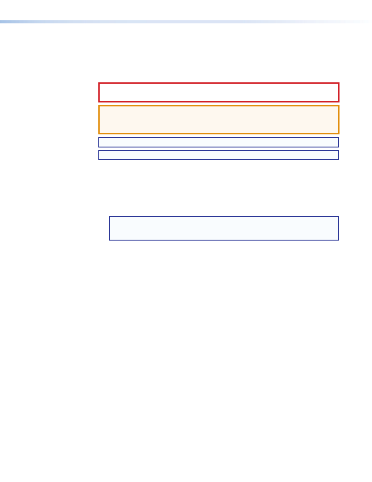
The following notifications are used in this guide:
CAUTION: Risk of minor personal injury.
ATTENTION : Risque de blessuremineure.
ATTENTION:
• Risk of property damage.
• Risque de dommages matériels.
NOTE: A note draws attention to important information.
TIP: A tip provides a suggestion to make working with the application easier.
Software Commands
Commands are written in the fonts shown here:
^AR Merge Scene,,0p1 scene 1,1 ^B 51 ^W^C.0
[01] R 0004 00300 00400 00800 00600 [02] 35 [17] [03]
E X! *X1&* X2)* X2#* X2! CE}
NOTE: For commands and examples of computer or device responses used in
Computer responses and directory paths that do not have variables are written in the
font shown here:
Reply from 208.132.180.48: bytes=32 times=2ms TTL=32
C:\Program Files\Extron
Variables are written in slanted form as shown here:
ping xxx.xxx.xxx.xxx —t
SOH R Data STX Command ETB ETX
Selectable items, such as menu names, menu options, buttons, tabs, and field names
are written in the font shown here:
From the File menu, select New.
Click the OK button.
this guide, the character “0” is used for the number zero and “O” is the capital
letter “o.”
Specifications Availability
Product specifications are available on the Extron website, www.extron.com.
Extron Glossary of Terms
A glossary of terms is available at http://www.extron.com/technology/glossary.aspx.
Page 6

Page 7

Contents
Introduction............................................................ 1
About This Guide ................................................ 1
About the DSC HD-HD 4K Plus A Series ........... 1
Features ............................................................. 2
Application Diagrams .......................................... 5
Installation .............................................................. 6
Rear Panel Features ........................................... 6
Connecting for 4K Processing .......................... 10
Single Input to Single Output ........................ 10
Single Input to Dual Outputs ......................... 11
Two Input Columns to Single Output ............. 12
Single Input to Two Output Columns ............. 12
Two Inputs to Two Side-by-Side Outputs ...... 13
Securing the HDMI Connector Using the
LockIt Cable Lacing Bracket ........................... 14
Connecting for Remote Control ........................ 14
Connecting to the RS-232 Port .................... 14
Connecting to the USB Config Port .............. 15
Operation .............................................................. 18
Front Panel Features ......................................... 18
On-screen Display Menu .................................. 19
Menu Overview ............................................. 19
Using the Front Panel Buttons with the
OSD Menu .................................................. 20
Using the OSD Menu .................................... 21
Quick Setup Submenu.................................. 22
Picture Controls Submenu ............................ 23
Input Submenu ............................................. 25
Output Submenu .......................................... 28
Audio Submenu ............................................ 31
Advanced Submenu ..................................... 33
Communications Submenu .......................... 35
Device Info Screen ........................................ 37
Auto-Image ...................................................... 37
Changing the Output Resolution and Refresh
Rate ................................................................ 38
Custom Rates .............................................. 38
Resetting the Output Rate ........................... 38
Power Save Mode ............................................ 39
Presets ............................................................. 39
Auto Memories ............................................. 39
Input Presets ................................................ 40
Locking the Front Panel (Executive Mode) ........ 40
Resetting .......................................................... 41
Remote Configuration and Control ................ 42
SIS Commands ................................................ 42
Copyright Information ................................... 43
DSC-initiated Messages ............................... 43
Error Responses ........................................... 44
Using the Command and Response Table .... 44
Symbol Definitions ........................................ 45
Command and Response Table for SIS
Commands ..................................................... 52
Product Configuration Software (PCS)
Program .......................................................... 71
Downloading the PCS Software from the
Website ....................................................... 71
Starting the Configuration Program ............... 73
Updating Firmware ........................................... 75
DSC HD-HD 4K Plus A Series Web Page ......... 76
Accessing the Web Page .............................. 76
Web Page Components ............................... 77
Special Characters ....................................... 82
Mounting ............................................................... 83
DSC HD-HD 4K Plus A Series • Contents vii
Page 8

DSC HD-HD 4K Plus A Series • Contents viii
Page 9

Introduction
This section provides an overview of the DSC HD-HD 4K Plus A scalers, covering the
following topics:
• About This Guide
• About the DSC HD-HD 4K Plus A Series
• Features
• Application Diagrams
About This Guide
The DSC HD-HD 4K Plus A Series User Guide describes the Extron DSC HDMI-to-HDMI
Digital Scaling Converters and provides instructions for experienced installers to install,
configure, and operate them.
In this guide, the terms “scaler,” “DSC,” and “DSC HD-HD 4K Plus A Series” are used
interchangeably to refer to the DSC HD-HD 4K Plus A and DSC HD-HD 4K Plus A xi.
Unless otherwise specified, the term “DSC HD-HD 4K Plus A” is also used to refer to both
models.
About the DSC HD-HD 4K Plus A Series
The Extron DSC HD-HD 4K Plus A and DSC HD-HD Plus A xi are high performance,
HDCP 2.2-compliant scalers capable of converting between HDMI resolutions up to 4K @
60 Hz with full 4:4:4 signal processing. They feature HDMI 2.0 connections that support
data rates up to 18 Gbps, and incorporate the Extron-exclusive Vector 4K scaling engine,
specifically engineered for critical-quality 4K applications. Both models support 4K @
60 Hz signals at 4:4:4 on a single connection, with the DSC HD-HD 4K Plus A xi also
supporting 4K @ 60 Hz signals as columns using two connections. The scalers feature
on-screen displays, stereo audio embedding and de-embedding, internal test patterns,
and the ability to display custom images and logos for on-screen corporate branding and
messaging. Remote configuration is available via USB and Ethernet, while external control
is available through RS-232 and Ethernet.
The Vector 4K scaling engine provides high-performance scaling with 30-bit precision
processing and 4:4:4 color sampling, as well as downscaling of 4K source signals for
interoperability with lower resolution displays or system components.
The DSC HD-HD 4K Plus A Series provides deinterlacing of all interlaced signals up to
1080i, Deep Color processing, and automatic 3:2 and 2:2 pulldown detection, and are
compatible with all DVI or HDMI display devices.
Audio integration capabilities include discrete, selectable analog and digital audio muting,
input gain and attenuation, and output volume control. They also include a two-channel
analog audio input for embedding audio onto the HDMI output and a two-channel
analog audio output for sending de-embedded audio to a sound system or other audio
destination.
Both models are housed in 1U high by one-half rack wide by 9.5 inches (24 cm) deep
enclosures and can be rack or furniture mounted.
DSC HD-HD 4K Plus A Series • Introduction 1
Page 10

Features
• 4K/60 HDMI video cross conversion — The DSC HD-HD 4K Plus A and
DSC HD-HD 4K Plus A xi provide high quality scaling and conversion of HDMI video
resolutions and frame rates.
• Inputs — One HDMI for DSC HD-HD 4K Plus A, two HDMI for DSC HD-HD 4K
Plus A xi, balanced or unbalanced stereo audio on 5-pole captive screw connectors.
• Outputs — One HDMI for DSC HD-HD 4K Plus A, two HDMI for DSC HD-HD 4K
Plus A xi, balanced or unbalanced stereo audio on 5-pole captive screw connectors.
• Accepts HDMI video from 480i up to 4096x2160/60 on a single connection
(non-xi model).
• Accepts HDMI video up to 4096x2160/60 using dual connections (DSC HD-HD
4K Plus A xi) — The xi model accepts up to 4K/60 video as a single input or as two
columns from a video source such as a workstation PC.
• Selectable output rates from 640x480 up to 4096x2160/60 on a single
connection (non-xi model).
• Selectable output rates up to 4096x2160/60 using dual connections
(DSC HD-HD 4K Plus A xi) — The xi model delivers 4K/60 video as a single output or
as two columns to a display, such as a large-venue projector. Alternatively, this model
can deliver two identical outputs up to 4K/60.
• Advanced Extron Vector 4K scaling engine — The Vector 4K scaling engine is
specifically designed for critical-quality 4K imagery, with best-in-class image upscaling
and downscaling.
• Advanced 30-bit precision processing with 4:4:4 color sampling — Performs
image scaling and video format conversion at 30-bit precision with 4:4:4 color
sampling for enhanced color accuracy and picture detail.
• Motion-adaptive deinterlacing for signals up to 1080i — Advanced deinterlacing
for all interlaced signals up to 1080i delivers optimized image quality.
• Displays user-supplied images for screen saver, corporate branding, logo
insertion, and HDCP notification — Custom user-loaded images can be displayed
as a screen saver after a predefined duration of inactivity at the video input, or
whenever the input is disconnected between presentations. User-supplied images
can also be displayed for HDCP Visual Confirmation, whenever HDCP-encrypted
content is transmitted to a non-HDCP compliant display.
• Logo image keying and display — A logo graphic may be placed at any position
on the video output as a foreground image. Logo graphics in BMP, JPG, PNG, or TIFF
format may be uploaded to the unit. Full screen images up to 4K resolution can also
be displayed to eliminate blank screens between presentations.
• HDCP 1.4 and 2.2 compliant — Ensures display of content-protected media and
interoperability with other HDCP-compliant devices.
• HDMI audio embedding — Audio from the two-channel analog input can be
embedded onto the HDMI output.
• HDMI audio de-embedding — Embedded HDMI two-channel PCM audio can be
extracted to the analog output.
• User-selectable HDCP authorization — Allows the unit to appear HDCP compliant
or non-HDCP compliant to the connected source, which is beneficial if the source
automatically encrypts all content when connected to an HDCP-compliant device.
Protected material is not passed in non-HDCP mode.
• Supported HDMI specification features include data rates up to 18 Gbps,
Deep Color, and HD lossless audio formats.
DSC HD-HD 4K Plus A Series • Introduction 2
Page 11

• EDID Minder automatically manages EDID communication between
connected devices — EDID Minder ensures that the source powers up properly and
reliably outputs content for display.
• Supports custom EDID and output resolutions — Three user-defined scaling
output resolutions can be supported by uploading custom EDID files, or capturing
EDID from a display or other destination device.
• Aspect ratio control — The aspect ratio of the video output can be controlled by
selecting a fill mode, which provides a full screen output, or a follow mode, which
preserves the original aspect ratio of the input signal.
• HDCP authentication and signal presence confirmation — Provides real-time
verification of HDCP status for the digital video input and output. This allows for quick
signal and HDCP verification through front panel LEDs, RS-232, USB, or Ethernet,
providing feedback to a system operator or help desk support staff.
• HDCP Visual Confirmation — A full-screen green signal or a user-supplied image
file is sent when HDCP-encrypted content is transmitted to a non-HDCP compliant
display, providing immediate visual confirmation that protected content cannot be
viewed on the display.
• HDMI to DVI Interface Format Correction — Automatically enables or disables
embedded audio and InfoFrames, and sets the correct color space for proper
connection to HDMI and DVI displays.
• Accu-RATE Frame Lock (AFL) — A patented technology exclusive to Extron that
locks the output frame rate to the input to eliminate stuttering caused by frame rate
conversion.
• Front panel LEDs for video, HDCP, and audio presence plus power — Provide
visual indication of system status for real-time feedback and monitoring of key
performance parameters.
• Image freeze control — A live image can be frozen using RS-232 serial control,
USB, or Ethernet control.
• Auto-Image setup — When Auto-Image is activated, the unit automatically
optimizes the image by analyzing and adjusting to the video input signal. This is useful
in setting up a newly connected source, particularly in presentation environments
where different guest presenter laptops with various output resolutions will be
connected.
• Auto Input Memory — When auto memory is activated, the unit stores size,
position, and picture settings based on the incoming signal. When the same signal is
detected again, these image settings are recalled from memory.
• On-screen menus — OSD menus enable system setup from the front panel
controls. Key parameters such as input and output video formats are grouped on the
initial Quick Setup screen, while additional screens provide full control over other unit
functions and settings.
• Output Standby Mode — The unit can be set to automatically mute video and sync
output to the display device when no active input signal is detected. This allows the
projector or flat-panel display to automatically enter into standby mode to save energy
and enhance lamp or panel life.
• Power Save Mode — The unit can be placed in a low power standby state to
conserve energy when not in use.
• Automatic 3:2 and 2:2 pulldown detection — Film mode processing techniques
help maximize image quality for NTSC, PAL, and 1080i sources that originated from
film.
DSC HD-HD 4K Plus A Series • Introduction 3
Page 12

• Picture controls for brightness, contrast, detail, horizontal and vertical
positioning, overscan, and sizing.
• Input presets — User memory presets are available for each input to store and recall
optimized image settings.
• Internal video test patterns and pink noise generator for calibration and
setup — The unit offers several video test patterns and audio pink noise to facilitate
proper system setup and calibration of display devices.
• Automatic input cable equalization — Actively conditions incoming HDMI signals
to compensate for signal loss when using long cables, low quality cables, or source
devices with poor signal output.
• Output volume control — Provides master volume control for the analog and HDMI
embedded audio outputs.
• Audio input gain and attenuation — Gain and attenuation can be adjusted for the
analog audio input.
• Integrated audio delay — The audio output is automatically delayed to compensate
for latency introduced by the video processing.
• Selectable audio muting — Incoming analog and HDMI embedded audio can be
muted. The audio can also be muted for the analog audio and HDMI outputs.
• Front panel security lockout — Locks out all front panel functions except for input
selection. (All functions, however, are available through Ethernet, USB, or RS-232
control.)
• Ethernet monitoring and control — Enables control and proactive monitoring
over a LAN, WAN, or the Internet. An intuitive Web interface is included for system
monitoring and firmware updates.
• Built-in Web pages — Enable the use of a standard browser for monitoring,
troubleshooting, and firmware upgrades over an intuitive Web interface.
• RS-232 control port — Enables the use of serial commands for integration into
a control system. Extron products use the SIS (Simple Instruction Set) command
protocol, a set of basic ASCII commands that enable programming of the unit.
• USB configuration port — The front panel USB Config port enables configuration
without having to access the rear panel.
• Product Configuration Software (PCS) — Enables configuration of multiple
products using a single software application.
• 1U, half rack width metal enclosure.
• LockIt HDMI cable lacing brackets provided.
• Internal universal power supply — The 100-240 VAC, 50-60 Hz, international
power supply provides worldwide power compatibility with high demonstrated
reliability.
DSC HD-HD 4K Plus A Series • Introduction 4
Page 13
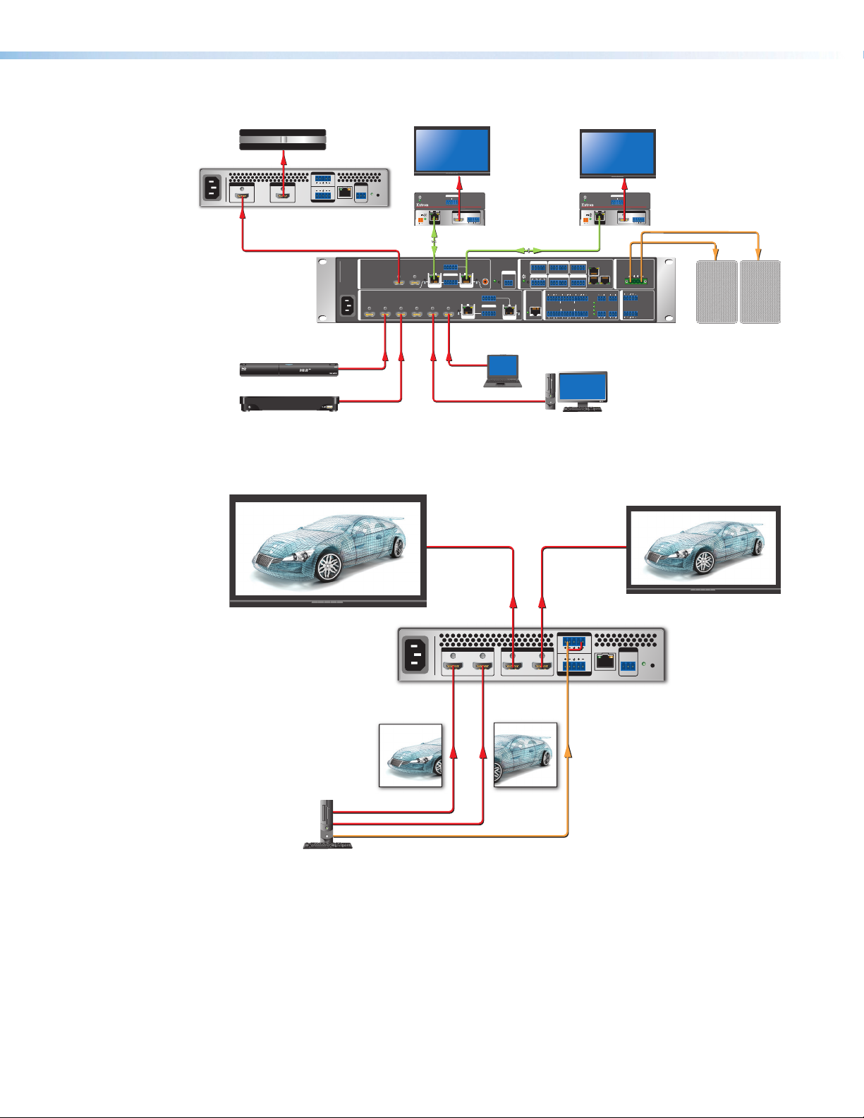
Application Diagrams
4K Media Player
Workstation PC
Workstation PC
HD VC Codec
100-240VAC ~ -- A MAX
50-60 Hz
INPUT
HDMI
DSC HD-HD 4K Plus A
HDMI 1080p
AUDIO IN
LR
LR
AUDIO OUT
REMOTE
LAN
RS -232
TxRx G
OUTPUT
HDMI
Extron
DSC HD-HD 4K Plus A
HDMI 4K
DTP CROSSPOINT 82 4K
100-240V ~ -- A MAX
1
50-60 Hz
HDMI 1080p
HDMI 4K
Extron
DTP CrossPoint
82 4K IPCP SA
Blu-ray Player
1A 2A
4K Display
POWER
12V
0.7A MAX
HDBT
RESET
OUTPUTS
1 2 3 4 5 6
INPUTS
SIG LINK
DTP IN
1B
SIG LINK
XTP
DTP
OUT
HDMI 4K
OVER DTP
IR
RS-232
TxRx Tx RxG
DTP HDMI 330 Rx
OUTPUTS
LR
CATx Cable
up to 330'
(100 m)
RS-232 IR
2B 4
TxRx Tx RxG
SIG LINK
OVER TP
RS-232 IR
OUT
G
TxRx Tx Rx
7
SIG LINK
XTP
DTP
IN
HDMI 4K
AUDIO
XTP
DTP
Extron
DTP HDMI
4K 330 Rx
Receiver
S/PDIF
OUT
RESET
HDBT
RS-232 IR
OVER TP
RS-232 IR
TxRx Tx RxG
Laptop
REMOTE
TxRx G
8
SIG LINK
XTP
DTP
IN
CATx Cable
up to 330'
(100 m)
CONTROL
Figure 1. DSC HD-HD 4K Plus A Application Example
HDMI
3840×2160 @ 60 Hz
with Audio
COM 1 COM 3COM 2 DIGITAL I/O
TxRx G Tx Rx G1234G
TxRx
RTSCTS
G
IR/SERIAL RELAYS DIGITAL I/O
12
12
R
SGSG
LR
1
2
LINK
LR4LR
AUDIO INPUTS
DMP EXPANSION
EXP
HDMI
3840×2160 @ 60 Hz
with Audio
C
34C+V
LR5LR
3
4K Display
SIG LINK
POWER
12V
0.7A MAX
DTP IN
LAN 1
+V D-S+S
LAN 2LAN 3
PWR OUT = 6W
+48V
1
2
6
LR
3
4
HDMI 4K
OVER DTP
Extron
IR
RS-232
TxRx Tx RxG
OUTPUTS
DTP HDMI 330 Rx
AUDIO
LR
DTP HDMI
4K 330 Rx
Receiver
Audio
8Ω / 4Ω
1
LR
AMP OUTPUT
CLASS 2 WIRING
LR
3
1
1
MIC/LINE
2
2
LR
4
AUDIO OUTPUTS
E E
Extron
SM 26
Surface Mount
Speakers
Extron
100-240VAC ~ -- A MAX
50-60 Hz
INPUT
AB
HDMI
DSC HD-HD 4K Plus A xi
OUTPUT
AB
HDMI
AUDIO IN
LR
LR
AUDIO OUT
LAN
DSC HD-HD 4K Plus A xi
1920×2160 @ 60 Hz
HDMI
HDMI
Audio
1920×2160 @ 60 Hz
Figure 2. DSC HD-HD 4K Plus A xi Application Example
REMOTE
RS -232
Tx Rx G
RESET
DSC HD-HD 4K Plus A Series • Introduction 5
Page 14

Installation
This section provides a description of the DSC HD-HD 4K Plus A Series rear panel
connectors and instructions for cabling. Topics include:
• Rear Panel Features
• Connecting for 4K Processing
• Securing the HDMI Connector Using the LockIt Bracket
• Connecting for Remote Control
ATTENTION:
• Installation and service must be performed by authorized personnel.
• L’installation et l’entretien doivent être effectués uniquement par un électricien
qualifié.
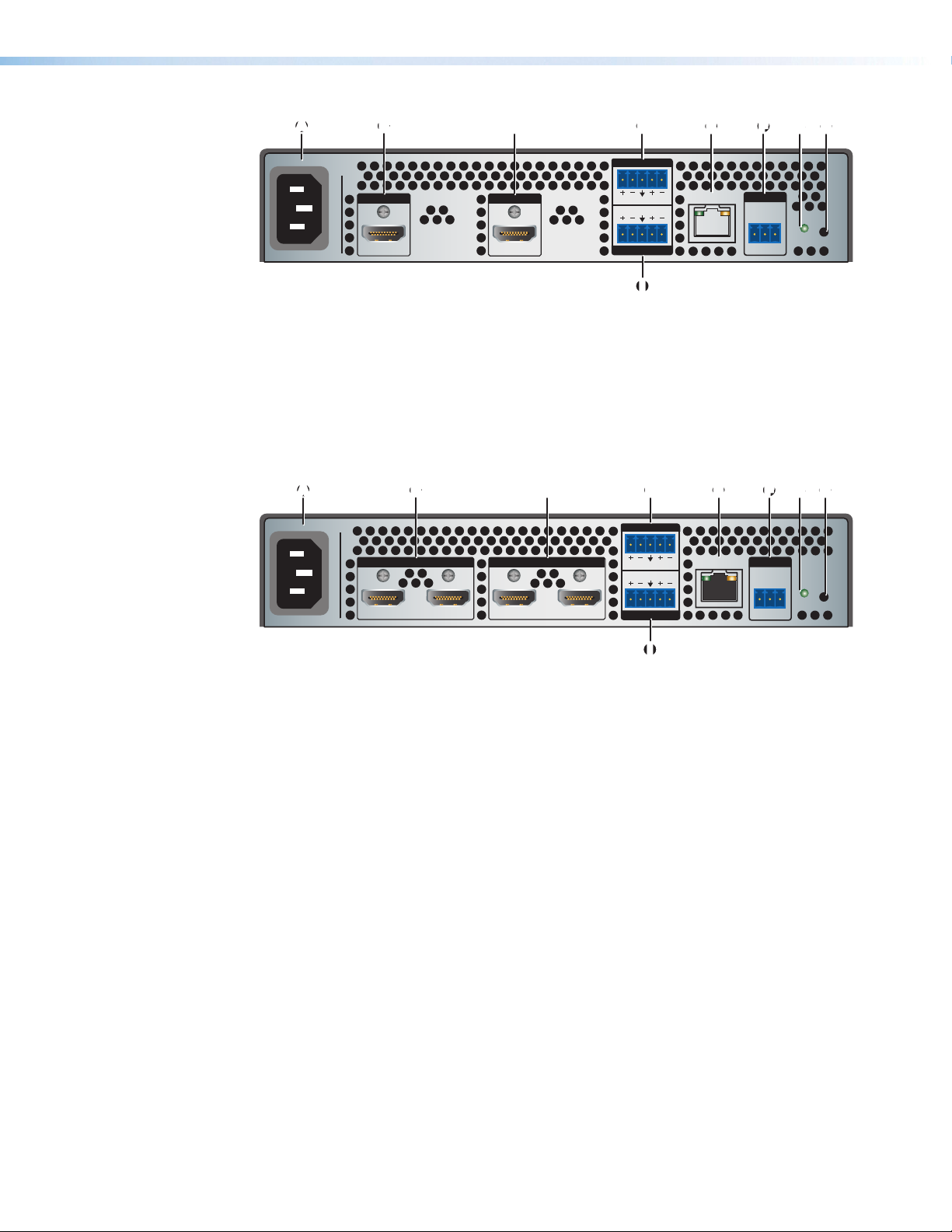
Rear Panel Features
The DSC HD-HD 4K Plus A Series consists of two models:
• DSC HD-HD 4K Plus A (standard) — One input and one output
• DSC HD-HD 4K Plus A xi — Two inputs and two outputs
On the next page, figure 3 shows the rear panel of the standard model and figure 4
shows the rear panel of the xi model.
CAUTION: Remove power from the system before making any connections.
ATTENTION : Couper l’alimentation avant de faire l’installation électrique.
ATTENTION:
• Use electrostatic discharge precautions (be electrically grounded) when making
connections. Electrostatic discharge (ESD) can damage equipment, although you
may not feel, see, or hear it.
• Prenez des précautions contre les décharges électrostatiques (soyez
électriquement relié à la terre) lorsque vous effectuez des connexions. Les
décharges électrostatiques (ESD) peuvent endommager l’équipement, même si
vous ne pouvez pas le sentir, le voir ou l’entendre.
DSC HD-HD 4K Plus A Series • Installation 6
Page 15
DSC HD-HD 4K Plus
AA
II
DSC HD-HD 4K Plus A xi
BB
CC
EE
FFDD
GG
HH
100-240VAC ~ 0.7 A MAX
A
INPUT
50-60 Hz
AC power connector
A
HDMI input connector
B
HDMI output connector
C
Audio input connector
D
Ethernet LAN connector
E
HDMI
OUTPUT
HDMI
F
G
H
I
AUDIO IN
LR
LR
AUDIO OUT
LAN
Remote RS-232 connector
Reset LED
Reset button
Audio output connector
Figure 3. Rear Panel, DSC HD-HD 4K Plus A (Non-xi Model)
AA
100-240VAC ~ 0.7 A MAX
50-60 Hz
BB
INPUT
AB
HDMI
CC
OUTPUT
AB
HDMI
DD
AUDIO IN
LR
LR
AUDIO OUT
EE
LAN
REMOTE
RS -232
Tx Rx G
FF
REMOTE
RS -232
Tx Rx G
GG
RESET
HH
RESET
II
AC power connector
A
HDMI input connectors
B
HDMI output connectors
C
Audio input connector
D
Ethernet LAN connector
E
Figure 4. Rear Panel, DSC HD-HD 4K Plus A xi
AC power connector — Connect the supplied US standard IEC power cable
A
between this IEC connector and a 110-220 V 50-60 Hz AC power source. The front
panel control and input selection buttons light in sequence during power-up.
HDMI input connectors — These inputs accept DVI and HDMI signals with or
B
without HDCP 1.4 or 2.2. You can enable or disable HDCP authorization using the
OSD menu system (see Input Submenu on page 25), SIS commands (see HDCP
Authorized commands on page 53), or the PCS software (see the program help file)
for more information.
• Standard model — Connect an HDMI source to this female HDMI connector.
• xi model — Connect one or two cables from an HDMI source to one or both of
these female HDMI connectors.
Secure the HDMI output cable to the HDMI connector using the LockIt bracket (see
Securing the HDMI Connector Using the LockIt Bracket on page 14).
Remote RS-232 connector
F
Reset LED
G
Reset button
H
Audio output connector
I
DSC HD-HD 4K Plus A Series • Installation 7
Page 16

HDMI output connectors — These outputs display the scaled video signals,
Unbalanced Stereo Input
Balanced Stereo Input
Slee
Do not tin the wires!
inch (5 mm) MAX.
C
support embedded digital audio signals, and are HDCP compliant. The xi model can
output two identical signals, or can output column 4K modes (see Connecting for
4K Processing on page 10 for more information).
• Standard model — Connect an HDMI output device to this female HDMI
connector.
• xi model — Connect one or two cables from one or both of these female HDMI
connectors to an output device.
Secure the HDMI output cable to the HDMI connector using the LockIt bracket (see
Securing the HDMI Connector Using the LockIt Cable Lacing Bracket on
page 14).
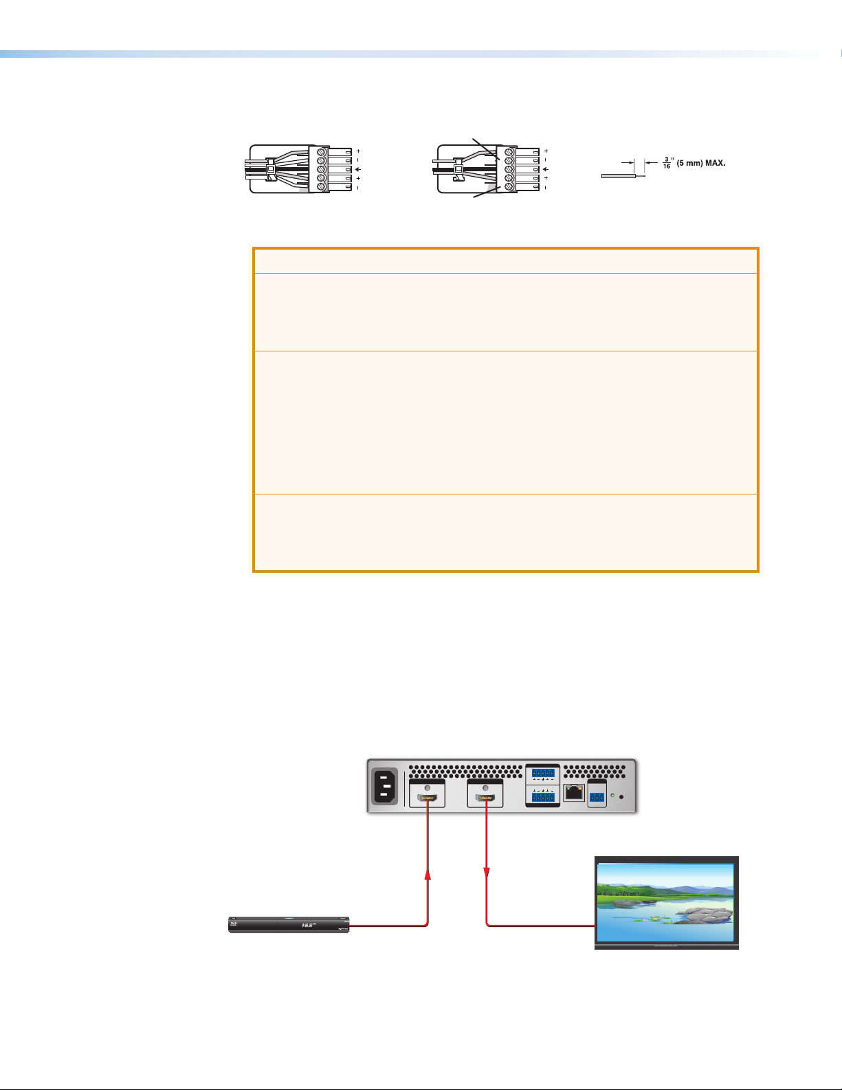
Audio input connector — If desired, connect a 2-channel balanced or unbalanced
D
analog audio source to this 5-pole captive screw connector to embed analog audio in
the HDMI output signal. Input gain range is -18 dB to +24 dB. The default is 0 dB.
Tip
Ring
ves
Tip
Ring
LR
Sleeve
Sleeve
Tip
Tip
LR
Figure 5. Wiring the Audio Input Connector
ATTENTION:
• The length of the exposed wires in the stripping process is critical. The ideal
length is 3/16 inch (5 mm). If the exposed portion is longer, the wires may
touch, causing a short circuit between them. If the exposed wires are shorter,
they can be easily pulled out, even if tightly fastened by the captive screws.
• La longueur des câbles exposés est primordiale lorsque l’on entreprend de
les dénuder. La longueur idéale est de 5mm (3/16inches). S’ils sont un peu
plus longs, les câbles exposés pourraient se toucher et provoquer un court
circuit. S’ils sont un peu plus courts, ils pourraient sortir, même s’ils sont
attachés par les vis captives.
• Do not tin the wires. Tinned wire does not hold its shape and can become
loose over time.
• Ne pas étamer les câbles. Les câbles étamés ne sont pas aussi bien fixés
dans les terminaisons des <connecteurs> à vis captives et pourraient sortir.
• For unbalanced audio, connect the sleeves to the ground contact. Do not
connect them to negative (–) contacts.
• Pour l’audio asymétrique, connectez les manchons au contact au sol. Ne
PAS connecter les manchons aux contacts négatifs (–).
DSC HD-HD 4K Plus A Series • Installation 8
Page 17

LAN port — Plug an Ethernet cable into this RJ-45 jack to connect the unit
reversed) is a "crossover" cable.
le that is wired the same at both ends
e
no pin or pair assignments are swapped.
Inser
Crossover Cable
Straight-through Cable
LAN
E
to a computer network. Ethernet control allows you to configure and control the DSC
from a remote location using SIS commands, the PCS software, or the embedded
Web pages. When connected to an Ethernet LAN, the DSC can be accessed from
a computer running a standard Internet browser. Use a patch or crossover cable to
connect the DSC to a switch, router, or computer.
The LAN connector contains two LEDs (see the illustration at right):
• Act LED — This amber LED blinks to indicate LAN signal activity.
• Link LED — This green LED lights steadily to indicate a LAN connection.
Pins:
12345678
t Twisted
Pair Wires
RJ-45
Connector
Pin
2
3
4
5
6
7
A cable that is wired as T568A at one end
and T568B at the other (Tx and Rx pairs
End 1 End 2
Wire color
1
White-green
Green
White-orange
Blue
White-blue
Orange
White-brown
8
Brown
T568A
Wire color
White-orange
Orange
White-green
Blue
White-blue
Green
White-brown
Brown
T568B
End 1 End 2
Wire color
Pin
1
2
3
4
Blue
5
White-blue
6
White-brown
7
Brown
8
T568B
A cab
is called a "straight-through" cable, becaus
Wire color
White-orangeWhite-orange
OrangeOrange
White-greenWhite-green
Blue
White-blue
GreenGreen
White-brown
Brown
T568B
F
G
H
Figure 6. Connecting to the LAN Port
Remote RS-232 connector — For serial RS-232 control, connect a host computer
or control system to this 3-pole captive screw connector (see Connecting for
Remote Control on page 14).
Reset LED — This green LED remains lit while the DSC has power. While the Reset
button (H) is being pressed and held, this LED blinks every 3 seconds to indicate the
level of reset that will be initiated if the button is released at that point (see Resetting
on page 41 for more information).
Reset button — This recessed button initiates levels (modes) of reset on the DSC.
To initiate the different reset levels, use a pointed object such as a small Philips
screwdriver or a stylus to press and hold the button while the DSC is running or while
it is being powered up (see Resetting).
DSC HD-HD 4K Plus A Series • Installation 9
Page 18
Audio output connector — Connect powered speakers or another audio output
Blu-r
Display
I
device to this 5-pole captive screw connector for analog output as shown in figure 7.
Tip
Ring
Sleeves
Tip
Ring
Balanced Audio Output
LR
No Ground Here
Tip
Sleeves
Tip
No Ground Here
Unbalanced Audio Output
LR
Do not tin the wires!
Figure 7. Wiring the Audio Output Connector
ATTENTION:
• For unbalanced audio, connect the sleeves to the ground contact. Do not
connect them to negative (–) contacts.
• Pour l’audio asymétrique, connectez les manchons au contact au sol. Ne
PAS connecter les manchons aux contacts négatifs (–).
• The length of the exposed wires in the stripping process is critical. The ideal
length is 3/16 inch (5 mm). If the exposed portion is longer, the wires may
touch, causing a short circuit between them. If the exposed wires are shorter,
they can be easily pulled out, even if tightly fastened by the captive screws.
• La longueur des câbles exposés est primordiale lorsque l’on entreprend
de les dénuder. S’ils sont un peu plus longs, les câbles exposés pourraient
se toucher et provoquer un court circuit. S’ils sont un peu plus courts, ils
pourraient sortir, même s’ils sont attachés par les vis captives.
• Do not tin the wires. Tinned wire does not hold its shape and can become
loose over time.
• Ne pas étamer les câbles. Les câbles étamés ne sont pas aussi bien fixés
dans les terminaisons des connecteurs à vis captives et pourraient sortir.
Connecting for 4K Processing
Input and output connections to the DSC HD-HD 4K Plus A Series can vary depending on
the capability of your source or sink to process signals at 4K resolution on a single cable.
Single Input to Single Output
For a single-input to single-output configuration, the source must be capable of passing a
4K signal on a single cable (see the example in figure 8).
DSC HD-HD 4K Plus A
3840 x 2160 @ 60Hz
with Embedded
Audio
ay Player
Figure 8. Single 4K Video Input to Single Output
If the sink will be displaying output at 4K as well, it must also be capable of receiving a 4K
signal on a single cable.
100-240VAC ~ -- A MAX
50-60 Hz
AUDIO IN
INPUT
HDMI
DSC HD-HD 4K Plus A
OUTPUT
HDMI
1080p @ 60Hz
with Embedded
Audio
LR
LR
AUDIO OUT
REMOTE
LAN
RS -232
RESET
Tx Rx G
DSC HD-HD 4K Plus A Series • Installation 10
Page 19

Single Input to Dual Outputs
Blu-r
Display
If you are connecting a source to two sinks and all devices are capable of processing 4K
on a single cable, the same image is displayed on both output devices (see the example
in figure 9). This configuration can be used for all non-4K resolutions as well.
DSC HD-HD 4K Plus A xi
3840 x 2160 @ 60Hz
with Embedded
Audio
ay Player
100-240VAC ~ -- A MAX
50-60 Hz
INPUT
AB
HDMI
DSC HD-HD 4K Plus A xi
OUTPUT
AB
HDMI
1080p @ 60Hz
with Embedded
Audio
1080p @ 60Hz
with Embedded
Audio
AUDIO IN
LR
LR
AUDIO OUT
LAN
REMOTE
RS -232
RESET
Tx Rx G
Display
Figure 9. Single Input (4K Video) to Two Output Devices
NOTE: If the 4K source or the 4K sink device supports 4K signals using columns,
connect the inputs and outputs as shown in figures 10 and 11 on the next page to
process 4K video.
DSC HD-HD 4K Plus A Series • Installation 11
Page 20

Two Input Columns to a Single Output
4K Video
Displa
y
0Hz
(left)
Blu-r
De-embedded
Input signals can be received over two wires in a “column” configuration (1920x2160,
2048x2160, and so on) and processed as a single, 4K image The left signal column is
sent through a cable from the source device to DSC Input A, and the right column through
a second cable to DSC Input B. The DSC combines the two input signal columns into one
signal, then displays a single 3840x2160 or 4096x2160 image on devices connected to
output A or to outputs A and B (see the example in figure 10).
Line-level Analog Audio
100-240VAC ~ -- A MAX
50-60 Hz
DSC HD-HD 4K Plus A xi
1920 x 2160 @ 60Hz
(left)
1920 x 2160 @ 60Hz
Figure 10. Left and Right Columns of 4K Video Input to a Single Output
Single Input to Two Output Columns
Output signals can be sent over two wires in a split, “column” configuration (1920x2160,
2048x2160, and so on) consisting of left and right halves of the image raster. The left
column (the left half of the image) is sent to the sink through a cable connected between
output A and the sink, while the right column is passed to the sink through another cable
connected to output B. The sink then combines the two columns and displays them as a
single image (see the example in figure 11).
INPUT
AB
HDMI
DSC HD-HD 4K Plus A xi
OUTPUT
AB
HDMI
3840 x 2160 @ 60Hz
with Embedded
Audio
AUDIO OUT
AUDIO IN
LR
LR
LAN
REMOTE
RS -232
RESET
Tx Rx G
Display
ay Player
Line-level Analog Audio
100-240VAC ~ -- A MAX
DSC HD-HD 4K Plus A xi
50-60 Hz
DSC HD-HD 4K Plus A xi
INPUT
AB
HDMI
OUTPUT
AB
HDMI
3840 x 2160 @ 60Hz
with Embedded
Audio
AUDIO IN
LR
LR
AUDIO OUT
REMOTE
LAN
RS -232
Tx Rx G
RESET
MPA 152 Plus
INPUTS
POWER
12V
0.7A MAX
L
R
MPA 152 Plus
8Ω / 4Ω
CLASS 2
WIRING
LR
L
SM 3 Speakers
Projector
3840 x 2160 @ 60Hz
with Embedded
Audio
1920 x 2160 @ 60Hz
Figure 11. Single HDMI Input to Left and Right Columns of 4K Video Output
DSC HD-HD 4K Plus A Series • Installation 12
OUTPUTS
R
REMOTE
VCG
10V
50mA
Page 21

Two Inputs to Two Side-by-Side Outputs
Blu-r
Display
Two HDMI inputs with the same resolution and refresh rate can be scaled and displayed
as two side-by-side images on one or both of the outputs (see the example in figure 12).
In this configuration, the aspect ratio selection (Fill or Follow) affects the appearance of
the output as follows:
• Fill — The image fills the vertical space on its portion of the display (stretched to fit if
necessary). This could result in a distorted image.
• Follow — The image is centered vertically on its portion of the display. If the image
takes up less vertical space than is available for it on the display, black bars are added
above and below the image to fill the space.
100-240VAC ~ -- A MAX
INPUT
AB
HDMI
DSC HD-HD 4K Plus A xi
50-60 Hz
DSC HD-HD 4K Plus A xi
Regional Sales
150
SOUTH
WEST
EAST
120
NORTH
90
60
30
0
4K Video
1080p @ 60 Hz
OUTPUT
AB
HDMI
3840 x 2160 @ 60 Hz
with Embedded
Audio
3840 x 2160 @ 60 Hz
AUDIO IN
LR
LR
AUDIO OUT
REMOTE
LAN
RS -232
RESET
Tx Rx G
Regional Sales
150
SOUTH
WEST
EAST
120
NORTH
90
60
30
0
Display
ay Player
Regional Sales
150
SOUTH
WEST
EAST
120
NORTH
90
60
30
1080p @ 60 Hz
3840 x 2160 @ 60 Hz
0
Figure 12. Two Inputs to Side-by-Side Display on One or Two Outputs
DSC HD-HD 4K Plus A Series • Installation 13
Page 22

Securing the HDMI Connector Using the LockIt Cable Lacing Bracket
After connecting an input or output device to
an HDMI connector, secure the connector in
place with the provided LockIt bracket as
follows:
1. Plug the HDMI cable into the panel
connection (1).
2. Loosen the HDMI connection mounting
screw from the panel enough to allow the
LockIt lacing bracket to be placed over it
(2).
3. Place the LockIt lacing bracket onto the
screw and slide it up against the HDMI
connector. Tighten the screw to secure the
bracket (3).
4. Loosely place the included tie wrap around
the HDMI connector and LockIt lacing
bracket (4).
5. While holding the connector securely
against the lacing bracket, tighten the tie
wrap, then remove any excess length.
111
333
3
222
444
Connecting for Remote Control
The DSC HD-HD 4K Plus A Series scalers have three control ports through which they
can be connected to a computer or control system for configuration and control: the rear
panel Remote RS-232 and LAN ports and the front panel USB Config port.
Connecting to the RS-232 Port
To connect a computer or control system to the DSC Remote RS-232 port, use an Extron
Universal Control cable (UC50' or UC100') or other female 9-pin-to-bare-wire RS-232
cable (see figure 13 on the next page).
1. Wire the unterminated end of the RS-232 cable to the provided 3-pole captive screw
connector as follows:
a. Connect the transmit wire to the left pin, which plugs into the Tx (transmit) port.
b. Connect the receive wire to the center pin, which plugs into the Rx (receive) port.
c. Connect the ground wire to the rightmost pin, which plugs into the ground port,
marked with G.
2. Plug the captive screw connector into the RS-232 port on the rear panel.
3. Connect the 9-pin connector end of the RS-232 cable to the serial port of the
computer or control system.
DSC HD-HD 4K Plus A Series • Installation 14
Page 23

RS-232
ol System
RS-232 Port
DSC HD-HD 4K Plus A Front Panel
Tx Rx
1 2 3
DSC Rear Panel
RS-232 Port
G
NOTES:
• For cable that has a drain wire, tie the drain
wire to ground at both ends.
• Connect a ground wire between the DSC
and the computer or control system.
Ground (G)
Receive (Rx)
Transmit (Tx)
Figure 13. Connecting to the RS-232 Port
See SIS Commands on page 42 for information on sending SIS commands through this
port.
Connecting to the USB Config Port
The USB mini-B USB Config port is located on the DSC front panel. It can be used to
configure the DSC via the PCS software or SIS commands.
1. Use a USB A-to-mini-B cable to connect the DSC USB Config port to a USB port on
a computer.
USB
Mini-B
Transmit (Tx)
Receive (Rx)
USB A
Computer or
Contr
USB 1
USB
Ports
USB Cable
DSC HD-HD 4K Plus A
CONFIG
INPUT OUTPUT
SIGNAL
HDCP
AUDIO
SIGNAL
HDCP
AUDIO
MENU
ENTER
HOLD FOR XGA/720p
AUTOIMAGE
Figure 14. Connecting to the Front Panel USB Config Port
DSC HD-HD 4K Plus A Series • Installation 15
Computer
Page 24

2. When the DSC is first connected to a particular USB port on the computer, one of the
following windows may open:
• Windows XP and earlier: If the following window opens, specify whether
Windows Update will search the Web for the driver needed for the computer to
communicate with the DSC via the USB port (this is not necessary if the USB
driver already exists on the computer).
Figure 15. Found New Hardware Wizard Opening Screen
Select one of the following radio buttons:
• Select the Yes, this time only radio button for the computer to connect to
Windows Update only this one time.
• Select the Yes, now and every time I connect a device radio button to
automatically connect to Windows Update every time the DSC is connected
to this USB port.
• Select the No, not this time radio button to not connect to Windows
Update at this time (for example, if the driver is already installed).
NOTE: This wizard appears only the first time the DSC is connected to each
USB port. It does not open again until you connect the DSC to a different
USB port.
DSC HD-HD 4K Plus A Series • Installation 16
Page 25

• Windows 7 and later: A pop-up notification appears on the Windows taskbar
informing you that Windows Update is searching the Web for the USB driver and
installing it. If desired, click the USB icon on the computer desktop to view the
progress of the search.
Figure 16. Selecting the Radio Button to Install the USB Driver
Automatically
NOTE: If you have uploaded the PCS software to your computer, the USB
driver is already installed and the screens do not appear.
• The Driver Software Installation window appears:
Figure 17. Driver Software Installation Window for USB Software
3. (Windows XP and earlier) Click Next. On the next screen, if asked whether to install
the driver automatically or from a specific location, select to install the software
automatically.
The computer locates the driver needed for it to communicate with the DSC via the
USB port.
4. Windows XP or earlier: When the Completed window appears, click Finish to
close the wizard.
Windows 7 or later: When the USB software has been located and downloaded, the
message Ready to use appears on the Driver Software Installation screen (a
pop-up message appears above the Windows taskbar if the screen is closed). Click
Close to close the status window.
DSC HD-HD 4K Plus A Series • Installation 17
Page 26
Operation
AA
BB
DD
C
C
F
F
This section discusses the functions available through the front panel and the on-screen
display (OSD) to configure and operate the DSC. Topics include:
• Front Panel Features
• On-screen Display Menu
• Auto-Image
• Changing the Output Resolution and Refresh Rate
• Power Save Mode
• Presets
• Locking the Front Panel (Executive Mode)
• Resetting
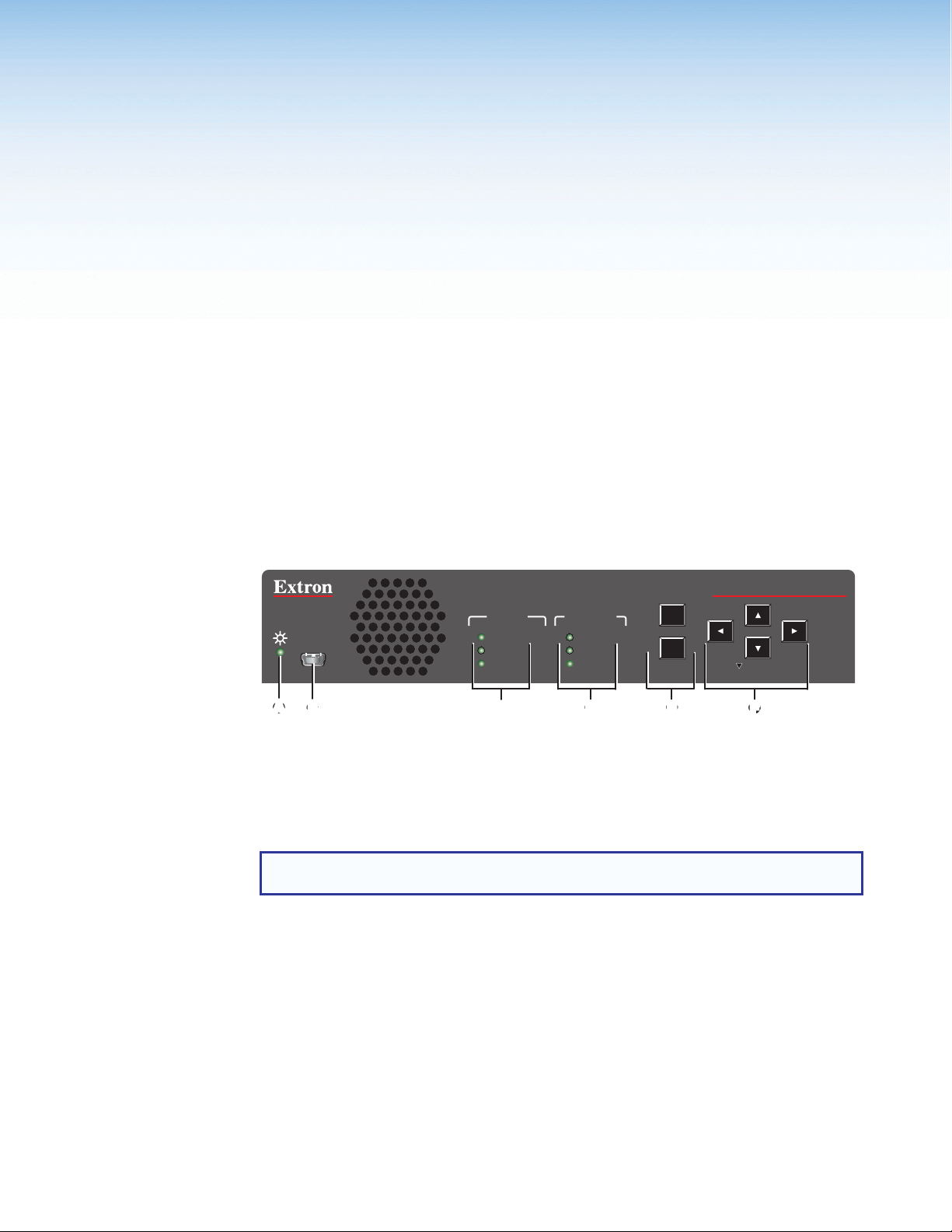
Front Panel Features
DSC HD-HD 4K Plus A xi
AUTO-
IMAGE
HOLD FOR XGA/720p
CONFIG
INPUT OUTPUT
SIGNAL
HDCP
AUDIO
SIGNAL
HDCP
AUDIO
MENU
ENTER
EE
Status LED (power and signal)
A
Config port
B
Input signal LEDs
C
Figure 18. DSC HD-HD 4K Plus A xi Front Panel
NOTE: Figure 18 shows the front panel of the xi model. The front panel of the non-xi
model is identical except for the product name in the upper-right corner.
Status LED (power and signal) — This bicolor LED lights steadily amber when
A
the unit is powered on but no signal is present, blinks amber every 3 seconds when
the unit is in standby mode, and lights steadily green when both power and an input
video signal are present.
USB configuration port — Connect a computer to this USB mini-B port for device
B
configuration and firmware upgrades.
Output signal LEDs
D
Menu and Enter Buttons
E
Navigation Buttons
F
DSC HD-HD 4K Plus A Series • Operation 18
Page 27

Input signal information LEDs — Light to indicate presence of an input signal and
C
the type of audio signal if one is also present.
• Signal — Indicates that an input signal is present.
• HDCP — Indicates that the input signal is HDCP-encrypted content.
• Audio — Indicates that an embedded audio signal is present on the input.
Output signal information LEDs
D
• Signal — Indicates that HDMI video is being output. (If the video is muted, this
LED does not light.)
• HDCP — Indicates that the output signal is HDCP-encrypted content.
• Audio — Indicates that an embedded audio signal is present in the output signal.
Menu and Enter buttons — Let you access and make selections from the
E
on-screen display menus (see Using the Front Panel Buttons with the OSD
Menus on the next page for detailed explanations of these buttons and the arrow
buttons).
Navigation Buttons (left t, right , up , and down arrows) — Let you
F
navigate through the OSD submenus, lock the front panel controls (see page 40),
perform Auto-Image (see page 37), and reset the output rate (see page 38).
On-screen Display Menu
The on-screen display menu enables you to configure and adjust the DSC from submenus
displayed on a monitor or other display device connected to a rear panel output.
NOTE: The settings available through the OSD menu can also be selected via SIS
commands (see the Remote Configuration and Control section, beginning on
page 42).
Menu Overview
The OSD menu has seven configuration submenus and one read-only information screen.
The OSD Menu Structure table on the next page shows the submenus and their items.
NOTE: The Device Info and Communication screens are read-only and give current
device status.
The menu screen always displays the following items, regardless of which submenu is
displayed.
• The Extron model name is in the upper-left corner.
• IP address and firmware version number are in the upper-right corner.
• Current input resolution and refresh rate are in the lower-left corner.
• Current output resolution and refresh rate are in the lower-right corner.
DSC HD-HD 4K Plus A Series • Operation 19
Page 28

OSD Menu Structure
Submenu Submenu Items
Quick Setup
Picture
Controls
Input
Output
Audio
Advanced
Communication
Device Info
(Read-only)
Input EDID Output Rate HDCP
Auto-Image Image
Film Detect Active
Output
Rate
Audio Mute Input Audio
Test Pattern Screen Saver Screen Saver
Serial Port MAC Address DHCP Mode IP Address Subnet
Unit Name
Firmware
Temperature
Position
(H and V)
Video
(H and V)
Output A
Format
-------Output B
Format
Format
Input A
-------Input B
Resolution,
Pixel Clock,
Total Lines,
HDCP Status
Authorized
Image Size
(H and V)
HDCP
Authorized
HDCP
Notification
Output Audio
Format
Timeout
Output A
-------Output B
Resolution,
Format,
Display Info,
HDCP Status
Auto Memory Aspect
Brightness Contrast Detail
Input EDID Capture
Input AFL Logo Logo
Analog Gain Volume
Aspect
Ratio
AFL
Ratio
Display
EDID
Auto
Memory
Mask
Test
Pattern
Position
Overscan Factory
Gateway
Output
Audio
Format
Reset
Using the Front Panel Buttons with the OSD Menu
Use the front panel Menu, Navigation, and Enter buttons to access, navigate, and
select items on the OSD menu.
• Menu — Press this button to activate or exit the OSD menu.
• Enter — Press this button to select submenus or submenu items, or to accept
pending changes (moves a yellow outline to the first submenu item in the right panel).
Press this button again to access the selections available from the outlined submenu.
• Navigation buttons —
• Press the Up arrow (
) and the Down arrow (<) buttons to navigate through the
>
submenus and submenu items.
The Down arrow button can also be used to reset the output rate (see Resetting
the Output Rate on page 38) and, in conjunction with the Menu button, to lock
the front panel (see Locking the Front Panel (Executive Mode) on page 40).
• Press the Right arrow () button to access the selections available for the
current submenu item.
When the OSD is closed, pressing this button performs an Auto-Image (see
Auto-Image on page 37).
• Press the Left arrow (t) button to exit a currently selected submenu or
submenu item.
DSC HD-HD 4K Plus A Series • Operation 20
Page 29

Using the OSD Menu
Figure 19. OSD Menu Initial View
To access and use the OSD menus:
1. Press the Menu button once to open the OSD menu on the display. The menu system
opens with the Quick Setup submenu displayed and the submenu name highlighted
in yellow in the left panel (see figure 19).
2. If you want to select a different submenu, press the front panel or button to
move the highlighting to the desired menu.
3. Press the Enter or button to access the menu items. A yellow outline appears
around the first item.
4. Press the or button to cycle through the items until the desired one is outlined.
5. Press the Enter button to select the outlined item. The selected item is outlined in
yellow. Yellow navigation arrows appear above, below, to the right, and to the left of
the selected item field, indicating the front panel arrow buttons that you can press to
move to the available selections.
Image Position
H: 0000 V: 0000
Figure 20. Example of a Selected Submenu Item
NOTE: When you select a Picture Controls submenu item (for example,
Brightness or Contrast), the OSD menu collapses so that the item is displayed
alone on the screen to facilitate adjustment (see Adjusting the picture
controls on page 24 to adjust settings on the Picture Controls submenu).
6. Press the arrow buttons to adjust the value as desired.
DSC HD-HD 4K Plus A Series • Operation 21
Page 30

7. Press Enter to confirm your new values. Press it again if action confirmation is
required.
8. Do any of the following:
• Press the
steps 5 through 7.
• Press t to exit the submenu. The yellow outline is removed from the item and
returns to the submenu name. If desired, use the and buttons to select
another submenu.
• Press Menu to exit the submenu and close the OSD menu.
NOTES:
• Settings in submenus that do not apply to the current input are shown as N/A.
• An asterisk following an item indicates that it is the default value.
• The OSD times out and closes after 1 minute if no buttons are pressed.
Quick Setup Submenu
This submenu provides access to common DSC settings.
or button to move to another item on the submenu and repeat
Figure 21. Quick Setup Submenu
From the Quick Setup submenu you can configure the following:
• Input EDID — Select this item to match the input EDID to the output rate or to set
a discrete EDID (see the Input EDID Resolutions table on page 26 for EDID data).
The default is Auto (match the current output resolution).
• Output Rate — Select this item to set the scaler output resolution and refresh
rate. The DSC HD-HD 4K Plus A Series scalers have 80 factory installed output
resolutions and rates and three custom user defined blocks for new resolutions (see
the Output Resolutions and Refresh Rates Table on page 29). The default setting
is 1080p @ 60 Hz.
DSC HD-HD 4K Plus A Series • Operation 22
Page 31

• HDCP Authorized — Select whether or not the scaler input will report to a source as
an HDCP authorized device, thereby allowing HDCP-encrypted content. The default
is On.
• Auto Memory — Select this item to enable or disable Auto Memories. When Auto
Memories are enabled, the DSC automatically stores the current input configuration
and picture control values as a preset in one of its 32 Auto Memory locations (see
Auto Memories on page 39 for more information). The default is On.
• Aspect Ratio — Select this item to specify whether input signals will fill the entire
output raster (Fill), or be automatically compensated to follow the native aspect
ratio of the input signal (Follow). The default is Fill.
• Test Pattern — Select this item to choose a test pattern to aid in setting up the
DSC and the corresponding output display. Available pattern selections are: Off (no
test pattern), Crop, Alternating Pixels, Crosshatch, Color Bars, Grayscale,
and Audio Test (displays a crop pattern and outputs 48 kHz, 24-bit pink noise). The
default is Off.
• Output Audio Format — Select between stereo and dual mono. The default is
Stereo.
Picture Controls Submenu
This submenu lets you adjust the horizontal and vertical positions, height and width,
brightness, contrast, and sharpness (Detail) of the image on the display.
Figure 22. Picture Controls Submenu
DSC HD-HD 4K Plus A Series • Operation 23
Page 32

The following picture settings can be adjusted:
• Auto-Image — Select this item, then press Enter to perform a one-time Auto-Image
on the video input (see Auto-Image on page 37 for more information about this
function).
• Image Position — Select this item to adjust the horizontal and vertical position of the
image on the display. The ranges are:
• Horizontal position: -4096 through +4096 pixels
• Vertical position: -2160 through +2160 lines
• Image Size — Select this item to adjust the horizontal size (width) and vertical size
(height) of the image. The ranges are:
• Horizontal size: 10 through 8192 of signal
• Vertical size: 10 through 4320 of signal
• Brightness — Select this item to adjust the black level of the video signal. The range
is 0 through 127. The default is 64.
• Contrast — Select this item to adjust the range of white to black levels of the video
signal. The range is 0 through 127. The default is 64.
• Detail — Select this item to adjust the image sharpness. The range is 0 to 127. The
default is 64).
NOTE: An asterisk (*) before a value on a screen indicates that it is the default.
Adjusting the picture controls
When you select a Picture Controls submenu item, the OSD menu collapses so that the
item is displayed alone on the screen to facilitate adjustment (see figure 23). The separate
item field contains yellow arrows that indicate which front panel arrow buttons to press to
adjust the item.
Image Position
Figure 23. Example of a Selected Picture Controls Submenu Item
After selecting the item to adjust, do the following:
1. With the separate item field displayed, use the arrow buttons to select and adjust the
desired settings as indicated by the yellow arrows on the screen. (To rapidly increment
or decrement the values, press and hold the arrow button.)
Example: In figure 23, the yellow right and left arrows next to the H setting indicate
that you can press the t and buttons on the front panel to adjust the horizontal position.
To adjust the vertical position, press the
and down arrows next to the V setting.
2. When finished, press Enter to return to the OSD menu.
H: 0000 V: 0000
and buttons, as indicated by the yellow up
DSC HD-HD 4K Plus A Series • Operation 24
Page 33

Input Submenu
This submenu allows you to perform certain input adjustments.
Figure 24. Input Submenu
From the Input submenu, you can configure the following:
• Film Detect — Select this item to enable and disable film detection, which helps
maximize image detail and sharpness for video sources originating from film. After
pressing Enter to select the item, press the or arrow buttons to toggle
between On (default) and Off.
If On is selected, the DSC detects and applies reverse pull-down for:
• 3:2 pull-down for 480i and 1080i @ 59.94 Hz
• 2:2 and 24:1 pull-down for 576i and 1080i @ 50 Hz
• Active Video — This view-only field shows the width in pixels (the H value) and the
height in lines (the V value) of the applied input signal.
• HDCP Authorized — Select this item to enable or disable HDCP communication by
selecting whether the DSC input will report to the source as an authorized HDCP sink.
After pressing Enter to select this item, press the or arrow buttons to toggle
between On (default) and Off.
Setting HDCP authorization to Off is useful for devices that always encrypt their
output if the downstream sink is capable of HDCP. If HDCP Authorized is disabled,
most content from these sources can be passed as a non-encrypted signal. In a
video system that should not transmit HDCP encrypted data, such as broadcast
or streaming environments, HDCP authorization should be disabled at the input to
ensure that the output remains unencrypted.
DSC HD-HD 4K Plus A Series • Operation 25
Page 34

Automatic
Output A HDMI
Output B HDMI**
Custom EDID 1
Custom EDID 2
Custom EDID 3
*Default EDID
**xi model only
• Input EDID — Select this item to select an EDID (resolution and refresh rate)
emulation for the HDMI inputs. You can match the input EDID to the output rate
or set a discrete EDID. The Input EDID Resolutions table below lists the available
EDID selections, including their SIS command variable numbers (see Remote
Configuration and Control, beginning on page 42, for information on SIS
commands).
NOTE: On the xi model, the EDIDs on HDMI inputs A and B always match.
Input EDID Resolutions
Resolution 23.98 Hz 24 Hz 25 Hz 29.97 Hz 30 Hz 50 Hz 59.94 Hz 60 Hz
0* — Match current scaler output resolution
1 (EDID export only)
2 (EDID export only)
640x480
800x600
1024x768
1280x768
1280x800
1280x1024
1360x768
1366x768
1440x900
1400x1050
1600x900
1680x1050
1600x1200
1920x1200
480p
576p
720p
1080i
1080p
2K (2048x1080)
2048x1200
2048x1536
2560x1080
2560x1440
2560x1600
3840x2160
3840x2160 Column**
4096x2160 Column**
26
29 30 31 32 33 34
35 36 37
38 39 40 41 42 43 44 45
46 47 48 49 50 51 52 53
59 60 61 62 63 64 65 66
101 102 103 104 105 106 107 108
111 112 113 114 115 116 117 118
201
202
203
24 25
10
11
12
13
14
15
16
17
18
19
20
21
22
23
54
55
56
57
58
DSC HD-HD 4K Plus A Series • Operation 26
Page 35

NOTE: EDID for 4096x2160 is not possible using native or preferred timings (4095
maximum active pixels). All factory EDIDs include a Video Identification Code (VIC)
in the EDID CEA extension block, so that if a 4096x2160 EDID is desired, Extron
recommends that the EDID be configured for 3840x2160 with the desired vertical
refresh rate.
• Capture Display EDID — Select this item to capture the EDID of the sink attached
to the output (output A on the xi model) and save it to one of the three custom EDID
slots. The DSC assigns the captured EDID to its input (both inputs A and B on the xi
model). To capture an EDID:
1. Select Capture Display EDID, then press Enter. A list of the three custom EDID
slots is displayed at the top of the OSD screen.
NOTE: If no EDID has been captured yet, the names displayed for the slots is
the default: 1280x720 @ 60 Hz (EXT). The last three letters in parentheses
represent the name of the display manufacturer (for example, EXT is an
abbreviation of Extron).
C1: C1 1920x1080 @ 60 Hz (SAM)
C1: C1 1280x720 @ 60 Hz (EXT)
C1: C1 1280x720 @ 60 Hz (EXT)
Figure 25. Custom EDID Slots List Example
2. Press the or arrow buttons to highlight the slot to which you want to save
the current display EDID.
3. Press Enter. The display EDID is saved to the selected custom slot and assigned
to the connected inputs.
DSC HD-HD 4K Plus A Series • Operation 27
Page 36

Output Submenu
This submenu allows you to configure the HDMI outputs of the DSC.
Figure 26. Output Submenu
• Output Rate — Select this item to specify the output resolution and refresh rate.
The DSC HD-HD 4K Plus A Series scalers have a range of resolutions from which
to choose (see the Output Resolutions and Refresh Rates table for the available
settings). The available rates depend on the selected resolution.
Three custom user-defined output rate slots are also available to be defined via
SIS commands or via the Capture Display EDID item on the Input menu. If
a custom EDID has not been captured from a display device or has not been
uploaded to the unit, these slots default to 720p @ 60 Hz. When a resolution
is applied to a user-defined EDID slot, its name is displayed in the Output
Resolution panel in the format cn: nnnnxnnnn @ nn (XXX). An example would be
C1: 1280x780 @ 60 Hz (EXT) (the last three letters in parentheses represent the name
of the manufacturer of the EDID).
DSC HD-HD 4K Plus A Series • Operation 28
Page 37

Output Resolutions and Refresh Rates
Resolution 23.98 Hz 24 Hz 25 Hz 29.97 Hz 30 Hz 50 Hz 59.94 Hz 60 Hz
640x480 X
800x600 X
1024x768 X
1280x768 X
1280x800 X
1280x1024 X
1360x768 X
1366x768 X
1440x900 X
1400x1050 X
1600x900 X
1680x1050 X
1600x1200 X
1920x1200 X
480p X X
576p X
720p X X X X X X
1080i X X X
1080p* X X X X X X X X*
2048x1080 X X X X X X X X
2048x1200 X
2048x1536 X
2560x1080 X
2560x1440 X
2560x1600 X
3840x2160 X X X X X X X X
4096x2160 X X X X X X X X
3840x2160 column** X X X X X X X X
4096x2160 column** X X X X X X X X
Custom output rate 1 New resolution 1
Custom output rate 2 New resolution 2
Custom output rate 3 New resolution 3
*Default rate **Supported on xi models only
To select an output rate:
1. Select Output Rate from the Output submenu and press the Enter button.
2. Press the or arrow buttons to select the resolution.
3. Press the button to move the yellow selection arrows to the rate and press the
or button to select a refresh rate.
4. Press the Enter button to confirm your selections.
5. Press t to return to the Input submenu.
NOTE: If you do not confirm your resolution and rate selection within 15 seconds,
the scaler returns to the previously selected resolution and rate.
DSC HD-HD 4K Plus A Series • Operation 29
Page 38

• Output Format — This item lets you set the HDMI output format and control the
output colorspace.
To select the format:
1. Select Output Format from the Output submenu and press Enter.
2. Press the or buttons to select the format.
3. Press Enter to confirm your selection.
4. Press t to return to the Output submenu.
The format choices are:
• Auto (based on the EDID of the sink) (default)
• DVI RGB 444
• HDMI RGB 444 Full
• HDMI RGB 444 Ltd
• HDMI YUV 444 Ltd
• HDMI YUV 422 Ltd
• HDMI YUV 420 Ltd
• HDCP Notification — This item lets you select what is displayed on the HDMI
output when the input signal contains HDCP-protected content and the output is a
non-HDCP sink. After pressing Enter to select this item, press the or arrow
buttons to select between:
• Green w/OSD — Displays a green screen with the message HDCP Content on the
HDMI output display (default).
• Black Screen — Displays a black screen and the output sync is maintained.
• User File — Displays a user-uploaded image. To upload images, use the PCS
software Logo screen (see the program help file for the procedure).
• Input AFL — This item lets you enable and disable the Extron Accu-RATE Frame
Lock (AFL). After pressing Enter to select this item, press the or arrow buttons
to toggle Input AFL on and off. The default is Off.
When On is selected, frame lock mode locks the output vertical refresh rate to the
vertical refresh rate of the currently selected input using Accu-RATE Frame Lock
technology. This ensures no frames of the input are repeated or dropped due to frame
rate conversion. Input AFL mode can cause glitches or interruptions in the output
sync when a new signal has been routed to the input, because the DSC locks to the
new vertical refresh rate.
NOTE: AFL locks the output refresh rate to the vertical rate of the input signal
only if they are similar frequencies. If the input refresh rate greatly differs from the
set output resolution, the DSC may not output a signal or may blink.
• Logo — Select this item to enable or disable display of a user-uploaded logo image.
There are 16 slots available for storing logo files. To upload a logo file to the unit, use
the Logo page of the PCS configuration program (see the program help file for the
procedure).
To select a logo to display:
1. Select Logo from the Output menu and press Enter.
2. Press the button to move the yellow selection arrows to the logo names list.
DSC HD-HD 4K Plus A • Operation 30
Page 39

• Logo Position — This item lets you specify a position for the selected logo on the
Audio Submenu
This submenu allows you to configure the audio that is processed through the DSC.
3. Press the or buttons to select a logo name. By default the logo slots are
named 01 through 16. Use the Logo SIS commands (see the Logos commands
beginning on page 59) or the Logo screen of the PCS software (see the program
help file) to change the logo name. The default is Off.
4. Press Enter to confirm your selection.
NOTE: To configure logo key effects (specify how the logo appears on the
display), see the PCS program help file.
display. The default is H: 0000 V: 0000. To position the logo:
1. Press the Enter button to select Logo Position from the Output submenu. The
yellow selection arrows move to the H: parameter.
2. Press the or arrow buttons to select the horizontal position.
3. Press the button to move the yellow selection arrows to the V: parameter and
press the or button to select the vertical position.
4. Press the Enter button to confirm your selections.
5. Press t to return to the Output submenu.
Figure 27. Audio Submenu
DSC HD-HD 4K Plus A Series • Operation 31
Page 40

To use this submenu, press Enter to select this item, then press the or buttons to
step through the selections.
• Audio Mute — Select this item to mute and unmute the output audio. You can make
the following audio mute selections:
• Off — No audio output is muted (default).
• Analog — Mutes the analog audio output only.
• Digital — Mutes the embedded digital audio output only.
• On — Mutes both the analog and the embedded digital audio outputs.
• Input Audio Format — Select this item to choose the audio format for the input. The
first item on the Audio menu shows the selected format of the audio.
Audio Format
Selection
None
Configures input EDID with no audio support. All audio outputs
Details
are muted.
Analog Audio Configures input EDID with no audio support. Analog audio
from the 5-pole captive screw input is embedded into the
HDMI output.
LPCM-2Ch
Configures input EDID for LPCM-2Ch support. Passes all
digital audio input signals to the HDMI outputs. If LPCM-2Ch
audio is present it is also de-embedded to the 5-pole captive
screw analog output.
Multi-Ch
Configures input EDID for Multi-Ch support. Passes all digital
audio input signals to the HDMI outputs. If LPCM-2Ch audio
is present it is also de-embedded to the 5-pole captive screw
analog output.
LPCM-2Ch Auto Configures input EDID for LPCM-2Ch support. Passes all
digital audio input signals to the HDMI outputs. If LPCM-2Ch
audio is present it is also de-embedded to the analog 5-pole
captive screw output.
If no embedded audio is present on the input the DSC passes
analog audio from the 5-pole captive screw input.
Multi-Ch Auto Configures input EDID for Multi-Ch support. Passes all digital
audio input signals to the HDMI outputs. If LPCM-2Ch audio
is present it is also de-embedded to the analog 5-pole captive
screw output. If no embedded audio is present on the input,
the DSC passes analog audio from the 5-pole captive screw
input.
• Output Audio Format — Select this item to specify stereo or dual mono (Mono) for
the analog audio output. Press Enter to select this item, then press the or
buttons to toggle between the two formats. The default is Stereo.
• Analog Gain — Select this item to set the analog input gain value. Press Enter to
select this item, then press the or buttons to increase or decrease the gain in
1 dB increments. The range is -18 dB through +24 dB. The default is 12 dB.
• Volume — Select this item to set the volume level in decibels for both the analog and
embedded digital audio outputs. Press Enter to select the item, then press the or
buttons to raise or lower the volume in increments of 1 dB. The range is -100 dB
through 0 dB. The default is -10 dB.
DSC HD-HD 4K Plus A Series • Operation 32
Page 41

Advanced Submenu
This submenu allows you to configure the global settings for the unit.
Figure 28. Advanced Submenu
The following items are available on the Advanced submenu:
• Test Pattern — Lets you choose a test pattern to use in setting up a display when
outputting different resolutions. The default is Off.
The following test patterns are available:
Crop
Color Bars
Alternating Pixels
Grayscale
Crosshatch
Audio Test
Figure 29. Test Pattern Items
NOTES:
• By default all test patterns include a single pixel wide crop pattern line.
• The Audio Test pattern displays a crop pattern and also outputs pink noise at
48 kHz, 24 bit.
• Test pattern selections persist through a power cycle.
DSC HD-HD 4K Plus A Series • Operation 33
Page 42

• Screen Saver — Configures device behavior when no active input signal is
detected. Options include a black (default) or blue screen, or a user provided logo file.
Optionally, you can set a timeout to disable the HDMI output after a set duration to
allow display devices (such as an LCD panel, plasma screen, or projector) to enter a
lower power or standby state to increase panel or lamp life.
To select the screen saver:
1. Select Screen Saver from the Advanced menu and press Enter.
2. Press the
or button to select the screen saver type. The menu selections
are:
• Black (default)
• Blue with a No Signal OSD message
• User Image — Displays an image that has been previously uploaded to the
DSC. The location of this image on the screen can be adjusted using the
OSD menu (see the Logo Position item of the Output menu on page 31),
SIS commands (see the Logo Horizontal Shift and Vertical Shift
commands on page 60) or the PCS software (see the program help file).
3. Press Enter to confirm your selection.
NOTE: The DSC exits screen saver mode when the front panel Menu or Enter
button is pressed, a video test pattern is activated, or an active input is
detected.
If the unit is in front panel lock mode (executive mode, see Locking the Front
Panel (Executive Mode) on page 40), pressing a front panel button exits time
out but access to any front panel controls or the menu system is disabled.
• Screen Saver Timeout — Lets you specify a number of seconds the selected
screen saver is displayed before the output sync times out. To set the sync timeout:
• Select Screen Saver Timeout from the Advanced menu and press Enter.
• Press the
out. You can select a duration of 0 (timeout is immediate) to 500 seconds before
the output sync times out. The default is Never, meaning that the sync does not
or button to select the amount of time before output sync times
time out.
• Aspect Ratio — Sets the aspect ratio to Fill (fills the entire output screen) or
Follow (follows the native aspect ratio of the input).
• In fill mode, if you want to set an aspect ratio adjustment for a single input
rate, you can select the correct size and position manually from the Picture
Controls submenu (Image Size and Position) (see Picture Controls
Submenu on page 23).
• In follow mode, each input rate is displayed with its native aspect ratio (4:3, 5:4,
16:9, or 16:10) with the correct letter box or pillar box settings, visible under the
Image Size and Image Position items on the Picture Controls submenu.
If you want a single input to fill the screen in follow mode, you can manually set
the Image Position item on the Picture Controls submenu to 0,0 and set the
Image Size to match the current output rate X, Y.
• Auto Memory — Enables or disables Auto Memory. When Auto Memory is set to On
(default), the DSC stores the current input configuration and picture control values as
an input preset (see Auto Memories on page 39 for more information).
DSC HD-HD 4K Plus A Series • Operation 34
Page 43

• Overscan — Lets you select a default overscan mode to apply to SMPTE input rates
(480i, 576i, 480p, 576p, 720p, 1080i, 1080p, 2K, and 4K). This zooms and crops
SMPTE inputs to mask edge effects and ancillary data that may occur in broadcast
signals. The selections are 0% (default), 2.5%, and 5%.
NOTE: If the overscan mode is not 1%, when Auto-Image is performed on an
SMPTE input rate, it refers to the default input values for sizing and centering
instead of performing a true Auto-Image.
• Factory Reset — Resets the unit to its factory default values (removing any
user-specified values) while retaining the current firmware version.
To reset using the OSD menu, press and hold the Enter button until Factory Reset
is displayed (approximately 5 seconds). The message remains for approximately
1 minute after the reset is complete to allow time for the display device to sync with
the DSC output.
NOTE: The equivalent SIS command is <ESC> ZXXX <CR>.
For other reset methods, see Resetting on page 41.
Communications Submenu
This menu enables you to view the RS-232 remote port baud rate, port type, and the unit
MAC address, and to edit the IP settings.
Figure 30. Communications Screen
DSC HD-HD 4K Plus A Series • Operation 35
Page 44

The Communications submenu contains the following items (see figure 30 on the
previous page):
• Serial Port — (View only) Displays the port type (RS-232) and the baud rate. The
protocols for this port is 9600 baud, eight data bits, no stop bits, and no parity.
• MAC Address — (View only) Displays the media access code (hardware address) of
the unit. This address is hard-coded at the factory and cannot be changed.
• DHCP Mode — When this mode is enabled (On), the unit configures its IP address
and other network settings from the DHCP server. The default is Off.
To enable or disable DHCP mode:
1. Select DHCP Mode from the Communications submenu and press Enter.
2. Press the
You can also set the DHCP mode via SIS commands (see the DHCP mode
commands on page 66), the PCS software, or the DSC HD-HD 4K Plus A series
website.
• IP Address — Lets you set the IP address for the unit. The default address is
192.168.254.254.
• Subnet Mask — Lets you set the subnet mask for the unit. The default subnet mask
is 255.255.0.0.
• Gateway — Lets you set the gateway address for the unit. The default gateway
address is 0.0.0.0.
or button to select On or Off and press Enter again.
Setting the IP, subnet mask, and gateway addresses
To set the IP address, subnet mask, or gateway address:
1. Select the item to be changed from the Communications submenu and press Enter.
2. Press the t and buttons to move the yellow selection arrows and highlighting to the octet
to be changed and press Enter.
3. Press the
4. To rapidly increase or decrease the octet value, press and hold the
until the desired value is displayed.
5. Repeat step 2 for the next octet to be changed, or press Enter again to return to the
submenu level.
or buttons to select the desired value for the octet, then press Enter.
or button
DSC HD-HD 4K Plus A Series • Operation 36
Page 45

Device Info Screen
This read-only screen provides a quick view of certain selections, parameters, and status
information for the DSC. i
Auto-Image
Figure 31. Device Info Screen Example
When Auto-Image is performed, the DSC attempts to size and position the image to fill
the display screen (fill mode) or use the native aspect ratio of the input (follow mode). Only
the horizontal and vertical positioning and the horizontal and vertical size are adjusted by
the Auto-Image. All other controls are left unchanged.
• If the aspect ratio has been set to Fill, the horizontal and vertical position returns to
0,0 and the horizontal and vertical size is set to match the current output rate.
• If the aspect ratio has been set to Follow, the horizontal and vertical position and
size are set to maintain the native aspect ratio of the input rate with respect to the
current output resolution.
Auto-Image is useful in applications in which a variety of new input sources may be
encountered (such as when a matrix switcher is connected). It is also useful for centering
and sizing an image that has been adjusted out of default settings. You can perform a
one-time Auto-Image by the following methods:
• Front panel button — While the OSD is not displayed, press the Auto-Image ()
button twice. The first press displays the message Press Auto again to Confirm on
the OSD. The second press initiates the Auto-Image.
• OSD submenu — Select Auto-Image from the Picture Controls submenu (see
page 23).
DSC HD-HD 4K Plus A Series • Operation 37
Page 46

• SIS commands (see the Auto-Image commands on page 52).
• PCS software (see the program help file).
Changing the Output Resolution and Refresh Rate
In addition to the Output submenu (see page 28), other methods for setting the output
resolution and refresh rate include resetting the output rate using the front panel button
(see Resetting the Output Rate), SIS commands (see the Output Configuration
commands beginning on page 57), and the PCS software program (see the program
help file).
Custom Rates
In addition to the 80 factory output resolutions, three custom user-defined rates are
available. Using SIS commands, the Capture Display EDID item on the Input submenu,
or the PCS software program, you can capture the EDID of the device connected to the
HDMI output or upload a custom EDID file from a computer (see the Output Scaler Rate
commands on page 57 or the PCS software program help file). When no custom EDIDs
are defined, these three resolutions and rates default to 1080p @ 60 Hz.
The OSD dynamically updates based on the current file stored in the custom EDID
slot. For example, if a custom 720p EDID has been uploaded, the OSD would display
C1: 1280x720 @ 60 Hz. See the Output Rate item of the Output submenu on page 28
for more information.
When you set this resolution using the menu system, a confirmation prompt appears. If
you do not respond to the prompt by pressing Enter within 20 seconds, the DSC reverts
to the previous resolution.
Resetting the Output Rate
If an output image cannot be displayed due to an incompatible output rate, you
can use the front panel down arrow button to toggle the output rate between
1024x768 @ 60 Hz (XGA) and 1280x720 (720p) @ 60 Hz. To set the rate or toggle
between the two rates:
1. Ensure that the OSD is closed by pressing and holding Menu for 3 seconds.
2. Press and hold the button until a message appears on the display indicating the
new rate (approximately 5 seconds).
NOTE: On the front panel, the button is labeled Hold for XGA/720p.
DSC HD-HD 4K Plus A Series • Operation 38
Page 47

Power Save Mode
In power save (standby) mode, all non-essential hardware is shut down in order to
conserve power. The default state for power save mode is Off.
• To enable power save mode, enter the Power Save ON SIS command (see the Power
• To exit power save mode, do one of the following:
NOTE: Many functions in the PCS software, such as backup and restore, are not
Presets
A preset is a set of input parameters that are either saved by you or automatically by
the DSC as a file in DSC memory. Saved presets can be recalled and their settings
implemented at any time. A preset saves time by enabling you to apply a group of settings
to the DSC at one time. The DSC HD-HD 4K Plus A Series scalers have two types of
presets: Auto Memories and input presets.
Save Mode commands on page 58). While the DSC is in power save mode, the
Status LED (power and signal) blinks amber slowly.
• Enter the Power Save OFF SIS command.
• Press any front panel button (if the front panel is locked, this method does not
work).
• Cycle power to the unit.
accessible while the unit is in power save mode.
Auto Memories
The DSC has 32 memory locations in which the current input configuration and picture
control values are automatically stored as a preset, when Auto Memory is enabled. An
Auto Memory preset is recalled when an identical input resolution and rate is applied to
the input.
Auto memories can be enabled using the OSD (see the Auto Memory item on
the Advanced submenu on page 34), by SIS commands (see the Auto Memories
commands on page 56), and the PCS software (see the program help file).
The following information is stored in an Auto Memory preset:
• Contrast • Horizontal image position
• Brightness • Vertical image position
• Detail • Horizontal image size (width)
• Active pixels (H Active) • Vertical image size (height)
• Active lines (V Active)
DSC HD-HD 4K Plus A Series • Operation 39
Page 48

Input Presets
The DSC HD-HD 4K Plus A Series scalers have 128 memory slots in which you can save
input presets. These presets allow a matrix switcher with multiple types of video inputs
(such as an XTP) to be placed upstream from the DSC to expand the number of video
sources. Input presets can be saved and recalled only through SIS commands (see the
Input Presets commands on page 57).
• When you recall an input preset, it fills the output raster based on the sizing and
• Input presets can be saved based on one input rate and recalled to a different rate.
Values for the following settings are saved in input presets:
Saving a preset when using a matrix switcher
When using the DSC with a matrix switcher, do the following to save a preset:
1. Switch each input of the matrix to the DSC.
2. Configure each input: size, position, detail, brightness, and contrast. The remaining
3. Save the settings to a preset for recall by the control system when that matrix input is
positioning that it had at the time it was saved.
This enables presets to be used as aspect ratio or other quick-sizing shortcuts.
• Contrast • Active lines (V Active)
• Brightness • Horizontal image position
• Detail • Vertical image position
• Film detect • Horizontal image size (width)
• Audio gain and attenuation • Vertical image size (height)
• Active pixels (H Active) • Preset name
settings (active pixels and lines) are not user-configurable, but are stored automatically
as part of the preset.
routed to the HDMI input.
Locking the Front Panel (Executive Mode)
To prevent access by unauthorized users or accidental changes to the DSC settings, you
can lock the front panel controls by placing the DSC in executive mode. In this mode, all
front panel buttons are disabled and control is available only by SIS commands.
To lock the front panel, do any of the following:
• Press and hold the front panel Menu and buttons until the OSD displays the
message Executive Mode Enabled (approximately 5 seconds). The message
remains on the OSD approximately 2 seconds.
• Enter the Enable SIS command (see the Front Panel Lock (Executive Mode)
commands on page 63).
• Select Lock Front Panel on the General Settings screen of the PCS software (see
the program help file).
To unlock the front panel, do any of the following:
• Press and hold the front panel Menu and buttons again until the OSD displays
the message Executive Mode Disabled (approximately 5 seconds). The message
remains on the OSD approximately 2 seconds.
• Enter the Disable SIS command (see the Front Panel Lock (Executive Mode)
commands).
• Select Unlock Front Panel on the PCS software General Settings screen (see the
program help file).
DSC HD-HD 4K Plus A Series • Operation 40
Page 49

Resetting
Resetting the unit causes various settings to revert to the defaults that were set at the
factory. Resets can be performed via the front panel buttons, the rear panel Reset button,
the OSD, the PCS software, or SIS commands. The following resets are available:
• Factory defaults — This reset clears all user-specified settings but retains the latest
firmware version. You can perform this reset by:
• Selecting Factory Reset from the Advanced submenu of the OSD (see the
Factory Reset item on the Advanced submenu on page 35)
• Entering the SIS command to reset all device settings to factory default (see the
Resets commands on page 64)
• Selecting Reset Device from the Device tab menu in the PCS software
When the reset is complete, the message Factory Reset is displayed on the OSD.
• Resetting using the Reset button — The Reset Modes Summary table
summarizes the reset modes that are accessible via the recessed Reset button on
the rear panel.
Reset Modes Summary
Mode Activation Result Purpose and Notes
1 Hold in the rear panel Reset button
while applying power to the unit.
4 Hold in the Reset button until the
Reset LED blinks twice (once after
approximately 3 seconds and
again after 6 seconds). Then, within
1 second, press Reset momentarily
(for less than 1 second).
• Restores the factory-installed default
firmware version for a single power
cycle.
• Retains all user files and settings,
including audio adjustments, and IP
settings.
• Sets the following to factory defaults:
• IP address — 192.168.254.254
• Subnet mask — 255.255.0.0
• Gateway address — 0.0.0.0
• DHCP — Off
Use mode 1 to
remove a version
of firmware for
one power cycle if
incompatibility issues
arise.
Mode 4 sets all IP
information to factory
defaults.
It does not replace
any user-installed
firmware.
• Sets port mapping to the factory
default.
The Reset LED blinks four times in quick
succession during the reset.
5 Hold in the Reset button until the
Reset LED blinks three times (once
after approximately 3 seconds, again
after 6 seconds, and then again after
9 seconds). Then, within 1 second,
press Reset momentarily (for less
than 1 second).
Performs a complete reset to factory
defaults except the firmware.
• Does everything that mode 4 does.
• Resets all user-modifiable
configuration to default values,
including IP settings and real-time
adjustments.
Mode 5 is useful if
you want to start
over with the default
configuration.
This is equivalent to
the SIS command
ZQQQ.
• Deletes all user-loaded files, including
user images.
The Reset LED blinks four times in quick
succession during the reset.
NOTE: Mode 5 reset clears all adjustments. To save these settings, use the PCS software program
and select Backup from the DSC HD-HD 4K Plus A tab menu before you perform this reset (see the
control program help file for more information).
DSC HD-HD 4K Plus A Series • Operation 41
Page 50

Remote Configuration and Control
This section describes the methods by which the DSC HD-HD 4K Plus A Series can be
configured and controlled remotely: the Extron Simple Instruction Set (SIS) commands,
the Web page, and the PCS software. It describes the available SIS commands and the
controls on the Web page and also provides instructions for obtaining and accessing the
PCS software. Topics include:
• SIS Commands
• Product Configuration Software (PCS) Program
• DSC HD-HD 4K Plus A Series Web Page
SIS Commands
You can use SIS commands to configure and control the DSC via a host computer or
other device (such as a control system) attached to the rear panel RS-232 connector, the
front panel USB port or the rear panel LAN port. Enter commands using an application
such as the Extron DataViewer, available at www.extron.com (see the DataViewer Help
file to use this program). The RS-232 port uses a protocol of 9600 baud, 8 data bits,
1 stop bit, no parity, and no flow control.
SIS commands consist of one or more characters per field. No special characters are
required to begin or end a command sequence. When the DSC determines that a
command is valid, it executes the command and sends a response to the host device.
All responses from the scaler to the host end with a carriage return and a line feed
(CR/LF = ]), indicating the end of the response character string (one or more characters).
DSC HD-HD 4K Plus A Series • Remote Configuration and Control 42
Page 51

Copyright Information
The DSC sends the following copyright message if power is cycled while the DSC
is connected to the host. It displays on the computer screen only with an RS-232
connection.
] (c) Copyright 20nn, Extron Electronics, DSC HD-HD 4K Plus A [xi], Vn.nn,
60-1573-0n]
Www, DD Mmm YYYY hh:mm:ss]
(Where 20nn is the year, Vn.nn is the firmware version, 60-1573-0n is the model number,
and Www is the day of the week.)
DSC-initiated Messages
When a local event such as a front panel selection or adjustment takes place, the
DSC responds by sending a message to the host. No response is required from the host.
Examples of DSC-initiated messages are listed below.
• Reconfig ]
The DSC sends this response when a change in the input frequency is detected.
• HplgO X@ * X6( ]
The DSC sends this response when hot plug event X6( is detected on output X@, for
example, when an HDMI output is unplugged and reconnected.
X@ = Output. For X@: 1 = HDMI A 2 = HDMI B (xi model only)
X6( = Hot plug change. For X6(: 1 = New sink connected 2 = Sink disconnected
• In00 • X6! ]
(Non-xi model) The DSC sends this response when a change in input signal presence
occurs.
X6! = Video signal status. For X6!:
0 = video signal not detected 1 = video signal detected
• In00 • X6! * X6! ]
(xi model) The DSC sends this response when a change in input signal presence
occurs on input A or B.
X6! = Video signal status (INA * INB). For X6!:
0 = video signal not detected 1 = video signal detected
• Hdcp I X! * X4$ ]
The DSC sends this response when a change in HDCP status of input X! occurs.
X4$ = HDCP status. For X4$:
0 = No source detected
1 = Source detected but no HDCP is present
2 = Source detected with HDCP
• Hdcp O X@ * X4$ ]
The DSC sends this response when a change in HDCP status of output X@ occurs.
X4$ = HDCP status. For X4$:
0 = No sink detected
1 = Sink detected but no HDCP is present
2 = Sink detected with HDCP
• Psav9 ]
The DSC sends this response when it enters power save mode due to the unit
exceeding its maximum operating temperature.
DSC HD-HD 4K Plus A Series • Remote Configuration and Control 43
Page 52

Error Responses
ASCII to HEX Conversion Table
•
Space
When the DSC receives a valid command, it executes the command and sends a
response to the host device. If the unit is unable to execute the command because the
command contains invalid parameters, it returns an error response to the host.
E01 — Invalid input number
E10 — Invalid command
E11 — Invalid preset number
E12 — Invalid port number
E13 — Invalid parameter
E14 — Invalid command for this configuration
E17 — Invalid command for signal type
E22 — Busy
E24 — Privilege violation
E28 — Bad file name or file not found
E33 — Bad file type or size
Using the Command and Response Table
The Command and Response Table for SIS Commands, beginning on page 52, lists
the commands that the DSC scaler recognizes as valid, the responses that are returned to
the host, a description of the command function or the results of executing the command,
and some examples of the command syntax in ASCII.
NOTE: Unless otherwise stated, upper- and lowercase text can be used
interchangeably in the commands.
Figure 32. ASCII to Hexadecimal Character Conversion Table
DSC HD-HD 4K Plus A Series • Remote Configuration and Control 44
Page 53

Symbol Definitions
• = Space
] = Carriage return with line feed
} or | = Carriage return with no line feed
E or W = Escape
24
= Superscripts indicate the error message displayed if the command is entered incorrectly
or with invalid parameters (see Error Responses on the previous page).
NOTE: If the unit does not support or recognize an entered command, it does not respond to
the command in any way.
X! = Input selection
1 = HDMI A
2 = HDMI B (valid on the xi model only)
X@ = Output
1 = HDMI A
2 = HDMI B (valid on the xi model only)
X# = Input video format
0 = No input signal detected
1 = HDMI
2 = DVI
X^ = Total lines
X& = Total pixels
Response is 4 digits, padded with zeros.
X* = Active pixels
Response is 4 digits, padded with zeros.
X( = Active lines
Response is 4 digits, padded with zeros.
X1) = On or off (enable or disable)
0 = Off or disable
1 = On or enable
X1@ = Internal temperature in degrees Celsius
Response is 2 digits.
X1# = Horizontal and vertical frequencies
Response format is 3 digits with leading zeros and one decimal place (example: 075.3).
X1$ = Text label, preset name, or logo name (up to 32 characters)
NOTES:
• Input presets saved without a name are given the default name Input
Preset nnn (for example, Input Preset 005).
• Logos saved without a name are given the default name Logo nn (for
example, Logo 05).
X1% = Picture adjustments — 0 to 127. Default is 64.
Response is 3 digits, padded with zeros.
X1^ = Horizontal and vertical position (depends on resolution)
Response is 5 digits with leading + or - and padded with zeros (example: -01075).
X1& = Horizontal and vertical size (depends on resolution)
Response is 5 digits, padded with zeros (example: 01075).
DSC HD-HD 4K Plus A Series • Remote Configuration and Control 45
Page 54

X2) = EDID emulation
Response is 3 digits padded with a zero.
0 = Automatic — Matches the current scaler output resolution (default)
Resolution 23.98 Hz 24 Hz 25 Hz 29.97 Hz 30 Hz 50 Hz 59.94 Hz 60 Hz
Automatic
Output A HDMI
Output B HDMI (xi models)
640x480
800x600
1024x768
1280x768
1280x800
1280x1024
1360x768
1366x768
1440x900
1400x1050
1600x900
1680x1050
1600x1200
1920x1200
480p
576p
720p
1080i
1080p
2048x1080
2048x1200
2048x1536
2560x1080
2560x1440
2560x1600
3840x2160
3840x2160 Column**
4096x2160 Column**
Custom EDID 1
Custom EDID 2
Custom EDID 3
0* — Match current scaler output resolution (EDID only)
1 (EDID export only)
2 (EDID export only)
38 39 40 41 42 43 44 45
46 47 48 49 50 51 52 53
59 60 61 62 63 64 65 66
101 102 103 104 105 106 107 108
111 112 113 114 115 116 117 118
201
202
203
*Default EDID **xi models only
NOTE: EDID for 4096 x 2160 is not possible using native or preferred timings (4095 maximum
active pixels). All factory EDIDs include a VIC (Video Identification Code) in the EDID CEA
extension block, so if 4096 x 2160 EDID is desired, it is recommended that EDID is configured
for 3840 x 2160 @ the desired vertical refresh rate.
10
11
12
13
14
15
16
17
18
19
20
21
22
23
24 25
26
29 30 31 32 33 34
35 36 37
54
55
56
57
58
DSC HD-HD 4K Plus A Series • Remote Configuration and Control 46
Page 55

X2! = Output scaler resolution
Response is 3 digits, padded with a zero.)
Output Resolutions and Refresh Rates (X2! = 10 through 203)
Resolution 23.98 Hz 24 Hz 25 Hz 29.97 Hz 30 Hz 50 Hz 59.94 Hz 60 Hz
640x480
800x600
1024x768
1280x768
1280x800
1280x1024
1360x768
1366x768
1440x900
1400x1050
1600x900
1680x1050
1600x1200
1920x1200
480p
576p
720p
1080i
1080p
2048x1080
2048x1200
2048x1536
2560x1080
2560x1440
2560x1600
3840x2160
4096x2160
3840x2160 Column**
4096x2160 Column**
Custom rate 1
Custom rate 2
Custom rate 3
*Default output resolution
**xi model only
26
29 63 31 32 33 34
35 36 37
38 39 40 41 42 43 44 45*
46 47 48 49 50 51 52 53
59 60 61 62 63 64 65 66
69 70 71 72 73 74 75 76
101 102 103 104 105 106 107 108
111 112 113 114 115 116 117 118
201
202
203
24 25
10
11
12
13
14
15
16
17
18
19
20
21
22
23
54
55
56
57
58
= Supports buffered output mode (xi model only)
= Supports left-right column mode only on outputs A and B respectively (xi model only)
NOTE: Custom output rates are supported only as buffered outputs and not column
outputs (xi model).
DSC HD-HD 4K Plus A Series • Remote Configuration and Control 47
Page 56

X2@ = Test patterns
Response is 2 digits padded with a zero.
0 = Off (default)
1 = Crop
2 = Alternating pixels
3 = Crosshatch
4 = Color bars
5 = Grayscale, 32-level split
6 = Audio Test (Crop pattern, OSD text Audio Test. Outputs pink noise at 48 kHz,
24 bits, channels 1 and 2.)
X2# = Input video mode
0 = Single channel mode (default)
1 = Left-right column mode (Input is paired with the adjacent input connector: A or B.)
X2^ = Input presets — 1 to 128
Response is 3 digits padded with zeros.
X2* = Output sync timeout — 1 to 500 seconds in 1-second increments
0 = The output sync is instantly disabled with no active input.
501 = The output sync never times out (default).
Response is 3 digits padded with zeros.
X2( = Front panel lock (executive mode)
0 = Disable lock mode (front panel controls are available) (default).
1 = Enable lock mode (front panel controls are locked).
X3) = OSD menu status
0 = Off (default)
1 = On (displayed)
X3! = Verbose mode
0 = None
1 = Verbose mode (default)
2 = Tagged response for queries
3 = Verbose mode and tagged response for queries
NOTES:
• In verbose response mode, the DSC responds with unsolicited responses for
value and setting changes that may result from a signal change, or a setting
adjustment made via another interface.
For example, the DSC can send out a notice of a change in some setting
without receiving a query via your PC. That change could have been a result of
an internal process, a selection made from the front panel, or a selection made
from the OSD. This is an example of a verbose (wordy) relationship between the
controller and a connected device.
• If tagged responses are enabled, all “view” commands return the command
string plus the data, the same as in responses for setting a value. For example:
Command: E M SSAV }
Response: SsavM X1! ] (tagged response)
or X1! ] (untagged response)
X3@ = Unit name — A text string of up to 63 characters. A-Z, 0-9, and the hyphen (-) are
permitted.
The first character must be a letter.
The last character cannot be a hyphen.
No distinction is made between uppercase and lowercase letters.
X3# = Default unit name:
DSC HD-HD 4K Plus A — DSC-HD-HD-4K-Plus-A-XX-XX-XX
DSC HD-HD 4K Plus A xi — DSC-HD-HD-4K-Plus-A-xi-XX-XX-XX
where XX-XX-XX are the last three character pairs of the MAC address of the unit.
DSC HD-HD 4K Plus A Series • Remote Configuration and Control 48
Page 57

X3$ = Model name
1 = DSC HD-HD 4K Plus A
2 = DSC HD-HD 4K Plus A xi
X3* = Overscan (Applied only to SMPTE input rates: 480i, 576i, 1080i, 1080p, 2K, and 4K)
0 = 0.0% — A true Auto-Image is executed on SMPTE inputs (default).
1 = 2.5% — Auto-Image commands snap to a 2.5% table (no true Auto-Image is
performed).
2 = 5.0% — Auto-Image commands snap to a 5.0% table (no true Auto-Image is
performed).
X3( = Aspect ratio
1 = Fill — Each input rate automatically fills the entire output raster (default).
2 = Follow — Each input rate is displayed with its native aspect ratio.
X4) = Screen saver mode
1 = Black screen (default)
2 = Blue output with OSD text
3 = User screen saver logo
X4@ = Video mute
0 = Off (unmute) (default)
1 = On (mute to black screen)
2 = On (mute all output sync and video)
X4# = User logo number
1 through 16. The response is 3 digits padded with leading zeros.
101 = Screen saver user logo
201 = User HDCP logo
X4$ = HDCP status
0 = No sink or source device detected
1 = Sink or source detected with no HDCP present
2 = Sink or source detected with HDCP present
X4^ = HDCP output mode
0 = Off — Disables all HDCP authentication and encryption attempts.
1 = Auto — Continuous authentication. Output is encrypted to HDCP only
when required by the input source, defaulting to the highest possible supported
encryption (default).
2 = On — HDMI outputs are always authenticated and encrypted.
X4& = HDCP notification mode
0 = Black screen — Notification disabled (mute output)
1 = Green screen with OSD message (default)
2 = User image
X4* = HDMI output format
0 = Auto (default). (HDMI RGB Full to HDMI sinks, or for pixel clocks greater than
165 MHz and DVI to DVI sinks [only if the current output resolution is less than
165 MHz]).
1* = DVI (RGB 444, 0-255, no audio, no InfoFrames. Valid for output rates up to
165 MHz.)
2 = HDMI RGB Full (RGB 444, 0-255, audio, InfoFrames)
3 = HDMI RGB Limited (RGB 444, 16-235, audio, InfoFrames)
5 = HDMI YUV Limited (YUV 444, 16-235, audio, InfoFrames)
7 = HDMI YUV Limited (YUV 422, 16-235, audio, InfoFrames)
9** = HDMI YUV Limited (YUV 420, 16-235, audio, InfoFrames)
* If the DSC is in DVI mode and a rate greater than 165 MHz is selected, the output
defaults to HDMI RGB 444 Full.
** 420 formats are available only when the current output resolution is 4K/UHD @ 59,
59.94, or 60 Hz and use half the TMDS character rate.
** If rates other than 4K/UHD @ 50, 59.94, or 60 Hz are set, the Auto format outputs only
HDMI RGB Full, and an E13 error code is returned if you attempt to set X4* to 8 or 9.
** If X4* is set to 8 or 9 and the output rate is changed to a rate other than 4K/UHD @ 50,
59.94, or 60 Hz, X4* is automatically set to 0 (Auto), and an SIS response is broadcast.
DSC HD-HD 4K Plus A Series • Remote Configuration and Control 49
Page 58

X4( = Unsolicited signal or HDCP status responses
0 = Disabled
1 = Enabled
X5) = Output volume
0 dB to -100 dB in 1.0 dB steps. Default is -10 dB.
Response is 3 digits padded with a leading + or – (examples: +000, -010).
X5! = Audio output format
1 = Dual mono
2 = Stereo (default)
X5$ = Audio input gain
-18 dB to +24 dB. Default is 12 dB.
Response is 2 digits padded with a leading zero.
X5* = Audio input format
0 = None. Audio is muted.
1 = Analog
2 = LPCM-2Ch
3 = Multi-Ch
4 = LPCM-2Ch Auto (default)
5 = Multi-Ch Auto
X6! = Video signal status
0 = Video signal not detected
1 = Video signal detected
X6@ = Power save modes
0 = Full power mode (default)
1 = Low power mode
9 = Low power due to overheating (response to query only)
X6# = Screen saver status
0 = Active input detected, timer not running
1 = No active input detected, timer running, output sync active
2 = No active input detected, timer expired, output sync disabled
X6$ = Input lock (AFL) setting
0 = Disable input lock. Free running pixel clock is generated internally (default).
1 = Enable input lock. Locks the output vertical rate to the vertical refresh rate of the
input.
X6% = Input lock (AFL) status
0 = Input lock (AFL) disabled
1 = Input lock (AFL) enabled, but cannot lock to applied input signal. The DSC defaults to
the current output rate and a free running pixel clock.
2 = Input lock (AFL) enabled, output locked to the applied input signal
X6^ = Input HDCP Authorized status
0 = HDCP Authorized disabled
1 = HDCP Authorized enabled (authenticated to the highest possible encryption
supported) (default)
X6( = Hot plug change or detect
1 = A new sink has been connected.
2 = A sink has been disconnected.
X7) = Key effect variable for logo
0 = Transparency (available only when X7$ = 1)
1 = Red of RGB key (available only when X7$ = 2)
2 = Green of RGB key (available only when X7$ = 2)
3 = Blue of RGB key (available only when X7$ = 2)
4 = Level key (available only when X7$ = 3)
5 = Alpha key
X7! = Key effect setting for logo
0 to 255
DSC HD-HD 4K Plus A Series • Remote Configuration and Control 50
Page 59

X7@ = Audio output mute
1 = Local 5-pole captive screw analog audio output
2 = Embedded TMDS audio output
X7$ = Label key effect
0 = Disabled
1 = Transparency
2 = RGB key
3 = Level key
4 = Alpha key
X7% = IP address (nnn.nnn.nnn.nnn). Leading zeros in each of the four octets are optional in
setting values and are suppressed in returned values.
Factory default address (when DHCP is turned off) is 192.168.254.254.
X7^ = Subnet mask (nnn.nnn.nnn.nnn). Leading zeros are optional in setting values in each of
the four octets, and are suppressed in returned values.
X7& = Gateway IP address (nnn.nnn.nnn.nnn). Leading zeros are optional in setting values in
each of the four octets, and are suppressed in returned values.
X7* = Password (12 characters maximum) The following characters are not allowed:
/ \ | * and {space}. Passwords are case-sensitive.
NOTE: A user password cannot be assigned if no administrator password exists.
An E14 error code is returned. If the administrator password is cleared, the user
password and all extended security level passwords are also removed.
X7( = Serial port baud rate
X8) = Serial port parity
X8! = Serial port number of data bits
X8@ = Serial port number of stop bits
X8# = Hardware (MAC) address (xx-xx-xx-xx-xx-xx)
X8$ = (Ethernet only) Number of seconds (stated in tens of seconds) before timeout on IP
connections
Minimum = 1 (10 seconds)
Maximum = 65000 (650,000 seconds)
Default = 30 (300 seconds)
Each step = 10 seconds
The response contains leading zeros.
If no data is received during the timeout period, the Ethernet connection is closed. When
the unit is connected via RS-232 or USB, only the global timeout commands apply.
Anything else returns an E13 error code.
X8% = Local date and time
Set format: MM/DD/YY-HH:MM:SS
Example: 06/21/15-10:54:00
View format: Www {day of the week}, DD Mmm YYYY HH:MM:SS
Example: Fri, 26 Sep 2015 18:19:33
X8^ = Greenwich Mean Time (GMT) offset value (-12:00 through 14:00) in hours and
minutes (hh:mm)
X8& = A 2- to 6-digit code, such as “PST” for GMT - 8.00
X8* = UTC offset and location name, such as (UTC-08:00) Pacic Time for PST
DSC HD-HD 4K Plus A Series • Remote Configuration and Control 51
Page 60

Command and Response Table for SIS Commands
Command ASCII Command
(Host to Scaler)
Response
(Scaler to Host)
Additional Description
Input Configuration
Input EDID
NOTES:
• Exporting a default EDID table (X2) value of 10 or greater) results in the Digital 2-Ch audio table being
exported.
• The lename can optionally consist of a full path name. The EDID file extension is .bin, carrying 128 or
256 bytes of binary data.
Assign EDID to input
View assigned EDID
data
Save HDMI output EDID
Export EDID file
Import EDID file
E A X! * X2) EDID } Edid A X! * X2) ]
E A X! EDID } X2) ]
In verbose modes 2 and 3:
Edid A X! * X2) ]
E S X@ * X2) EDID } Edid S X@ * X2) ] Save HDMI output X@ EDID to
E E X2), lename EDID }
Edid E X2) ] Export EDID table X2) to file
E I X2), lename EDID }
Edid I X2) ] Import EDID table X2) from
Assign EDID resolution and
refresh rate X2) to input X!.
View assigned EDID resolution
and refresh rate X2) for input
X!.
custom EDID X2). X2) can be
201, 202, or 203.
lename.
file lename. Valid only when
X2) = 201, 202, or 203.
Auto-Image
Execute
Execute and Fill
Execute and Follow
Active Pixels
View
Active Lines
View
1*0A
1*1A
1*2A
Img 1*0 ]
Img 1*1 ]
Img 1*2 ]
E 1 APIX } X* ]
In verbose modes 2 and 3:
Apix1* X* ]
E 1 ALIN } X( ]
In verbose modes 2 and 3:
Alin1* X( ]
Perform an Auto-Image on the
current input (follows current
aspect ratio setting).
Perform an Auto-Image and fill
entire display screen.
Perform an Auto-Image and
follow the input aspect ratio.
Show active pixels X* for the
input. X* is 4 digits padded
with zeros.
Show active lines X( for the
input. X( is 4 digits padded
with zeros.
NOTE: X! = Input number: 1 or 2 (2 is available on the xi model only)
X@ = Output number: 1 or 2 (2 is available on the xi model only)
X* = Number of active pixels
X( = Number of active lines
X2) = EDID emulations: 0 = Automatic: matches current output resolution (default), 201 = Custom EDID 1,
202 = Custom EDID 2, 203 = Custom EDID 3
For variables 10-87, see the SIS EDID table on page 46.
DSC HD-HD 4K Plus A Series • Remote Configuration and Control 52
Page 61

Command ASCII Command
(Host to Scaler)
Input Configuration (continued)
Total Lines
View total lines
E 1 TLIN } X^ ]
Total Pixels
View total pixels
E 1 TPIX } X& ]
3:2, 2:2, and 24:1 Film Detection
Enable auto detection
Disable auto detection
View film detect setting
E 1*1 FILM } Film 1*1 ]
E 1*0 FILM } Film 1*0 ]
E 1 FILM } X1) ]
HDCP Authorized
HDCP authorized
E E 1* X6^ HDCP } Hdcp E 1* X6^ ] Set HDCP Authorized to X6^.
Response
(Scaler to Host)
In verbose modes 2 and 3:
Tlin 1* X^ ]
In verbose modes 2 and 3:
Tpix 1* X& ]
In verbose modes 2 and 3:
Film 1* X1) ]
Additional Description
Show total number of lines (X^)
for the input.
Show the total number of pixels
(X&) for the input.
Enable automatic detection of
film mode (3:2, 2:2, and 24:1
pull-down).
Disable automatic film detect
detection.
View the current film detect
setting (X10).
View HDCP authorized
device status
E E 1 HDCP } X6^ ]
In verbose modes 2 and 3:
Hdcp E 1 * X6^ ]
HDCP Status
View input status
View output status
NOTE: X! = Input number: 1 or 2 (2 is available on the xi model only)
E I X! HDCP } X4$ ]
In verbose modes 2 and 3:
Hdcp I X! * X4$ ]
E O X@ HDCP } X4$ ]
In verbose modes 2 and 3:
Hdcp O X@ * X4$ ]
X@ = Output number: 1 or 2 (2 is available on the xi model only)
X^ = Total lines
X& = Total pixels
X1) = Automatic film detection status: 0 = disabled, 1 = enabled (default is 1)
X4$ = Input or output HDCP status: 0 = no sink or source device detected, 1 = sink or source device with HDCP
detected, 2 = sink or source detected with no HDCP
X6^ = HDCP Authorized status: 0 = HDCP Authorized off, 1 = HDCP Authorized on (the input reports as an
HDCP authorized device to allow HDCP input signals). (Default is 1).
View HDCP authorized device
status X1).
View HDCP status X4$ for input
X!.
View HDCP status X4$ for
output X@.
DSC HD-HD 4K Plus A Series • Remote Configuration and Control 53
Page 62

Command ASCII Command
(Host to Scaler)
Response
(Scaler to Host)
Picture Adjustment
Video Mute — Individual Output (Defaults to Unmuted after a power cycle.)
Mute video to black
Mute sync and video
Unmute output video
and sync
View mute
X@ *1B Vmt X@ *1 ] Mute video on output X@,
X@ *2B Vmt X@ *2 ]
X@ *0B Vmt X@*0 ]
X@ *B X4@ ]
In verbose modes 2 and 3:
Vmt X@ * X4@ ]
Video Mute — Global (Defaults to Unmuted after a power cycle.)
Mute video to black
Mute sync and video
Unmute video and sync
View global mute
1B
2B
0B
B
Vmt 1]
Vmt 2]
Vmt 0 ]
Non-xi model:
X4@ ]
In verbose modes 2 and 3:
Vmt X4@ ]
xi model:
X4@ • X4@ ]
In verbose modes 2 and 3:
Vmt X4@ • X4@ ]
Contrast
Set a specific value
Increment contrast value
Decrement value
View contrast
E 1* X1% CONT } Cont 1 * X1% ]
E 1+ CONT } Cont 1 * X1% ]
E 1- CONT } Cont 1 * X1% ]
E 1 CONT } X1% ]
In verbose modes 2 and 3:
Cont 1 * X1% ]
Additional Description
displaying a black screen.
Mute video and sync on HDMI
output X@.
Display the selected input on
HDMI output X@.
View mute status X4@ of output
X@.
Mute video on all outputs,
displaying black screens.
Mute video and sync on all
outputs.
Display all outputs.
View video mute status X4@ of all
outputs.
Set the range of image light
and dark values (contrast level)
to X1% for the current input.
Increase the contrast level by 1.
Decrease the contrast level by
1.
View the current contrast level
for the current input.
NOTE: X@ = Output number: 1 or 2 (2 is available on the xi model only)
X1% = Picture adjustment: 0 through 127 (default is 64)
X4@ = Video mute: 0 = mute off (default), 1 = mute on (mute to black screen), 2 = mute on (mute all output sync
and video)
DSC HD-HD 4K Plus A Series • Remote Configuration and Control 54
Page 63

Command ASCII Command
(Host to Scaler)
Picture Adjustment (continued)
Brightness
Set a specific value
Increment value
Decrement value
View
E 1* X1% BRIT } Brit 1 * X1% ]
E 1+ BRIT } Brit 1 * X1% ]
E 1- BRIT } Brit 1 * X1% ]
E 1 BRIT } X1% ]
Detail Filter
Set detail level
Increment value
Decrement value
View
E 1* X1% HDET } Hdet 1 * X1% ]
E 1+ HDET } Hdet 1 * X1% ]
E 1- HDET } Hdet 1 * X1% ]
E 1 HDET } X1% ]
Horizontal Shift (Image)
Specific value
Increment value
Decrement value
View
E I 1* X1^ HCTR} Hctr I 1* X1^ ]
E I 1+ HCTR } Hctr I 1* X1^ ]
E I 1- HCTR } Hctr I 1* X1^ ]
E I 1 HCTR} X1^ ]
Vertical Shift (Image)
Specific value
Increment value
Decrement value
View
E I 1* X1^ VCTR } Vctr I 1* X1^ ]
E I 1+ VCTR } Vctr I 1* X1^ ]
E I 1- VCTR } Vctr I 1* X1^ ]
E I 1 VCTR }
Response
(Scaler to Host)
In verbose modes 2 and 3:
Brit 1 * X1% ]
In verbose modes 2 and 3:
Hdet 1 * X1% ]
In verbose modes 2 and 3:
Hctr I 1* X1^ ]
In verbose modes 2 and 3:
Vctr I 1* X1^ ]
Additional Description
Set the intensity of video light
on the screen (brightness level)
to X1% for the current input.
Increase the brightness level
by 1.
Decrease the brightness level
by 1.
View the current brightness
level for the current input.
Set the sharpness (detail) level
to X1% for the current input.
Increase the detail level by 1.
Decrease the detail level by 1.
Show the detail level for the
current input.
Set the horizontal position of
the image in relation to the
center of the screen to X1^.
Shift image right 1 pixel.
Shift image left 1 pixel.
View image horizontal centering
value X1^.
Set the vertical position of the
image in relation to the center
of the screen to X1^.
Shift the image down by 1 line.
Shift the image up by 1 line.
View image vertical centering
value X1^.
NOTE: X1% = Picture adjustment: 0 to 127 (default is 64).
X1^ = Horizontal or vertical image position: Response is 5 digits with leading + or - and padded with zeros.
DSC HD-HD 4K Plus A Series • Remote Configuration and Control 55
Page 64

Command ASCII Command
(Host to Scaler)
Picture Adjustment (continued)
Horizontal Size (Image)
Specific value
Increase horizontal size
Decrease horizontal size
View
E I 1* X1& HSIZ} Hsiz I 1* X1& ]
E I 1+ HSIZ } Hsiz I 1* X1& ]
E I 1- HSIZ } Hsiz I 1* X1& ]
E I 1 HSIZ } X1& ]
Vertical Size (Image)
Specific value
Increase vertical size
Decrease vertical size
View
E I 1* X1& VSIZ } Vsiz I 1* X1& ]
E I 1+ VSIZ } Vsiz I 1* X1& ]
E I 1- V SIZ } Vsiz I 1* X1& ]
E I 1 VSIZ } X1& ]
Compound Image Position and Size
Specific value
E 1, X1^ * X1^ * X1& * X1& XIMG }
Response
(Scaler to Host)
In verbose modes 2 and 3:
Hsiz I 1* X1& ]
In verbose modes 2 and 3:
Vsiz I 1* X1& ]
Additional Description
Set the horizontal size (width) of
the image to X1&.
Widen the image by 1 pixel.
Narrow the image by 1 pixel.
View horizontal size X1&.
Set the vertical size (height) of
the image to X1&.
Make the image taller by 1 line.
Shorten the image by 1 line.
View vertical size X1&.
View
Presets
Auto Memories
Enable
Disable
View setting
Ximg 1, X1^ * X1^ * X1& * X1& ]
E 1 XIMG } 1, X1^ * X1^ * X1& * X1& ]
In verbose modes 2 and 3:
Ximg 1, X1^ * X1^ * X1& * X1& ]
E 1*1 AMEM } Amem 1*1 ]
E 1*0 AMEM } Amem 1*0 ]
E 1 AMEM } X1) ]
In verbose modes 2 and 3:
Amem 1* X1) ]
Set the horizontal and vertical
position (X1^) and horizontal
and vertical size (X1&) for the
image.
View x, y position and x, y size
for image.
Set Auto Memory to On.
Settings are automatically
stored as presets. Previous
settings for the incoming signal
are recalled.
Set Auto Memory to Off.
Manual recall of input presets is
required to configure the input.
View current Auto Memory
status X1).
NOTE: X1) = Enable or disable Auto Memories: 0 = Off or disable, 1 = On or enable (default)
X1^ = Horizontal or vertical position: Response is 5 digits with leading + or - and padded with zeros.
X1& = Horizontal or vertical size. Response is 5 digits with leading + or - and padded with zeros.
DSC HD-HD 4K Plus A Series • Remote Configuration and Control 56
Page 65

Command ASCII Command
(Host to Scaler)
Response
(Scaler to Host)
Presets (continued)
Values Saved in Input Presets
Input Presets
Contrast Preset Name H Image Position
Brightness Audio Gain and Attenuation V Image Position
Detail H Active (Pixels) H Image Size
Film Detect V Active (Lines) V Image Size
Input Presets
Recall preset
Save preset
Delete preset
2*1* X2^ . 2 Rpr 1* X2^ ] Recall input preset X2^ for the
2*1* X2^ , 2 Spr 1* X2^ ] Save input preset X2^ for the
E X 2 * X2^ PRST } Prst X 2* X2^ ] Clear input preset X2^ and set
Input Preset Name
Write name
View name
E 2* X2^ , X1$ PNAM }
Pnam 2* X2^ , X1$]
E 2* X2^ PNAM } X1$ ]
In verbose modes 2 and 3:
Pnam 2* X2^ , X1$ ]
Additional Description
selected input.
selected input.
its name to [unassigned].
Set the name of input preset
X2^ to X1$.
View the name (X1$) of input
preset X2^.
NOTE: Unsaved input presets are shown as [unassigned]. To restore a default input preset name, enter a single
space character for X1$. These entries are valid only for previously saved presets.
Output Configuration
Output Scaler Rate
Set output rate
View output rate
NOTE: X1$ = Preset name, up to 16 characters
E 1* X2! RATE } Rate 1* X2! ]
E 1 RATE } X2! ]
In verbose modes 2 and 3:
Rate 1* X2! ]
Select the output resolution
and refresh rate (X2!).
Show the selected output rate.
X2! = Output resolution and refresh rate: 10 – 87.
201 = Custom rate 1, 202 = Custom rate 2, 203 = Custom rate 3,
For variables 10-87, see the Output Resolutions and Refresh Rates table on page 47.
Response is 2 digits padded with a zero.
X2^ = Input preset number: 1 – 128. Response is 3 digits padded with zeros.
DSC HD-HD 4K Plus A Series • Remote Configuration and Control 57
Page 66

Command ASCII Command
(Host to Scaler)
Output Configuration (continued)
HDMI Output Format
Set format
View setting
E X@ * X4* VTPO } Vtpo X@ * X4* ] Set output format X4* for HDMI
E X@ VTPO } X4* ]
Power Save Mode
Power save off
Power save on
E 0 PSAV } Psav 0 ]
E 1 PSAV } Psav 1 ]
Response
(Scaler to Host)
In verbose modes 2 and 3:
Vtpo X@ * X4* ]
Additional Description
output X@.
Show current HDMI output
format (X4*) for output X@.
Set the DSC to run in full power
mode (default).
Place the DSC in low power
mode.
NOTE:
View setting
This mode can be exited via the E 0 PSAV } command, by pressing any button on the front panel, or by
::
connecting the DSC to the computer via the PCS software.
E PSAV } X6@ ]
In verbose modes 2 and 3:
Psav X6@ ]
Screen Saver (displayed when no active video signal is detected on the HDMI input)
Set screen saver mode
View mode
Set screen saver
duration before output
sync timeout
View screen saver
duration before output
sync timeout.
View screen saver
status
NOTE: X@ = Output: 1 = output A, 2 = output B (xi model only)
E M 1* X4) SSAV} Ssav M 1* X4) ]
E M 1 SSAV } X4) ]
In verbose modes 2 and 3:
Ssav M 1* X4) ]
E T 1* X2* SSAV} Ssav T 1* X2* ]
E T 1 SSAV } X2* ]
In verbose modes 2 and 3:
Ssav T 1* X2* ]
E S 1 SSAV } X6# ]
In verbose modes 2 and 3:
Ssav S 1* X6# ]
X2* = Screen saver duration before output sync timeout — 1 through 500 seconds, in 1-second increments.
0 = The output sync is instantly disabled with no active input.
501 = Output sync never times out (default).
X4) = Screen saver mode: 1 = black screen (default), 2 = blue output with OSD text
X4* = HDMI output format:
0 = Auto (default). (HDMI RGB Full to HDMI sinks, or for pixel clocks greater than 165 MHz and DVI to
DVI sinks [only if the current output resolution is less than 165 MHz]).
1 = DVI (RGB 444, 0-255, no audio, no InfoFrames. Valid for output rates up to 165 MHz.)
2 = HDMI RGB Full (RGB 444, 0-255, audio, InfoFrames)
3 = HDMI RGB Limited (RGB 444, 16-235, audio, InfoFrames)
5 = HDMI YUV Limited (YUV 444, 16-235, audio, InfoFrames)
7 = HDMI YUV Limited (YUV 422, 16-235, audio, InfoFrames)
9 = HDMI YUV Limited (YUV 420, 16-235, audio, InfoFrames)
X6@ = Power saver mode: 0 = full power mode (default), 1 = low power due to overheating (query only)
X6# = Screen saver status:
0 = active input detected, timer not running
1 = No active input detected, timer running, output sync active
2 = No active input detected, timer expired, output sync disabled
View power save status X6@.
Set the screen saver mode to
X4). Default = 1 (black).
View current screen saver
mode X4).
Set the screen saver timeout
duration to X2* seconds.
Default = 501 (never).
View screen saver timeout
duration X2*.
View screen saver status X6#.
DSC HD-HD 4K Plus A Series • Remote Configuration and Control 58
Page 67

Command ASCII Command
(Host to Scaler)
Output Configuration (continued)
Input lock (Accu-Frame Lock [AFL])
Disable input AFL
Enable input AFL
View the AFL setting
View AFL status
E 1*0 GLOK } Glok 1*0 ]
E 1*1 GLOK } Glok 1*1 ]
E 1 GLOK } X6$ ]
E 41 STAT } X6% ]
Logos
User Supplied Image
Select image file
View logo image file
E A X4#, lename LOGO}
E A X4# LOGO} lename ]
Clear Logo Setting
Clear logo
E X 3* X4# PRST} Prst X 3* X4# } Clear logo slot X4# and
Logo On or Off
Disable logo
Enable logo
View logo status
E E 1*0 LOGO } Logo E 1*0 ]
E 1* X4# LOGO } Logo E 1* X4# ]
E E 1 LOGO } X4# ]
Logo Name
Write name
View logo name
E L X4#,X1$ UNAM } Unam L X4#,X1$ ] Apply logo name X1$ to logo
E L X4# UNAM } X4# ]
Logo Availability
View logo availability
E Q LOGO } <16 characters>*<1 character>*<1 character> ]
Response
(Scaler to Host)
In verbose modes 2 and 3:
Glok 1* X6$ ]
In verbose modes 2 and 3:
41 Stat • X6% ]
Logo A X4#, lename ]
In verbose modes 2 and 3:
Logo A1,lename ]
Additional Description
Disable global input lock (AFL).
Lock the output refresh rate to
the rate of the input.
View the current global input
lock (AFL) setting.
View the current global input
lock (AFL) or genlock status X6%.
Assign logo lename to logo
slot X4#.
View the logo filename assigned
to logo slot X4#.
change setting name to
[unassigned].
Disable display of the current full
screen notification logo.
Display the logo assigned to slot
X4#.
View logo slot X4# for which the
In verbose modes 2 and 3:
Logo E 1* X4# ]
logo is enabled.
X4#.
View the name assigned to logo
In verbose modes 2 and 3:
Unam L X4#,X1$ ]
In verbose modes 2 and 3:
Logo Q <16 characters>*<1 character>*<1
character>]
X4#.
1 = saved, 0 = empty
NOTE: The first 16 digits denote logo images, the digit immediately following the first * indicates the screen saver logo,
and the last digit (following the second *) indicates the HDCP logo.
NOTE: X1$ = Logo name (up to 32 characters)
X4# = User logo number: 1 – 16. 0 = logo is disabled, 101 = screen saver user logo, 102 = HDCP user logo.
X6$ = Input lock (AFL): 0 = disable input lock. Free running pixel clock is generated internally (default).
1 = enable input lock. Locks the output vertical rate to the vertical refresh rate of the input.
X6% = Input lock (AFL) status: 0 = Input lock is disabled. 1 = Input lock is enabled but cannot lock to the input
signal. 2 = Input lock is enabled. The output is locked to the input signal.
DSC HD-HD 4K Plus A Series • Remote Configuration and Control 59
Page 68

Command ASCII Command
(Host to Scaler)
Logos (continued)
Horizontal Shift (Logo)
Specific value
Increment value
Decrement value
View
E L X4# * X1^ HCTR} Hctr L X4# * X1^ ]
E L X4# + HCTR } Hctr L X4# * X1^ ]
E L X4# - HCTR } Hctr L X4# * X1^ ]
E L X4# HCTR} X1^ ]
Vertical Shift (Logo)
Specific value
Increment value
Decrement value
View
E L X4# * X1^ VCTR} Vctr L X4# * X1^ ]
E L X4# + VCTR } Vctr L X4# * X1^ ]
E L X4# - VCTR } Vctr L X4# * X1^ ]
E L X4# VCTR } X1^ ]
Logo Key Effect
Disabled
Transparency
RGB Key
Level Key
Alpha Key
View setting
E X4# *0 LKEF } Lkef X4# *0 ] Disable key effect for logo X4#.
E X4# *1 LKEF } Lkef X4# *1 ] Enable transparency for logo X4#
E X4# *2 LKEF } Lkef X4# *2 ] Enable RGB key for logo X4#.
E X4# *3 LKEF } Lkef X4# *3 ] Enable Level key for logo X4#.
E X4# *4 LKEF } Lkef X4# *4 ] Enable Alpha key for logo X4#.
E X4# LKEF } X7$ ]
Logo Key Effect Level
Specific value
View setting
E X4# * X7) * X7! *LKEY }
E X4# * X7) LKEY } X7! ]
Response
(Scaler to Host)
In verbose modes 2 and 3:
Hctr L X4# * X1^ ]
In verbose modes 2 and 3:
Vctr L X4# * X1^ ]
In verbose modes 2 and 3:
Lkef X4# * X7$ ]
Lkey X4# * X7) * X7! ]
In verbose modes 2 and 3:
Lkey X4# * X7) * X7! ]
Additional Description
Set the horizontal centering of
logo X4# to X1^.
Shift logo right 1 pixel.
Shift logo left 1 pixel.
View horizontal centering value
X1^.
Set the vertical centering of
logo X4# to X1^.
Shift logo down 1 pixel.
Shift logo up 1 pixel.
View vertical centering value
X1^.
View the current key effect (X7$)
for logo X4#.
Set the level for key effect
variable X7) to X7! for logo X4#.
View level X7! set for key effect
variable X7) for logo X4#.
NOTE: X1^ = Horizontal or vertical position of logo: Response is 5 digits with leading + or - and padded with zeros.
Range depends on resolution.
X4# = User logo number: 1 – 16. Response is 3 digits padded with a zero.
101 = screen saver user logo, 102 = HDCP user logo.
X7) = Key effect variable:
0 = transparency (available only when X7$ = 1)
1 = Red of RGB key (available only when X7$ = 2)
2 = Green of RGB key (available only when X7$ = 2)
3 = Blue of RGB key (available only when X7$ = 2)
4 = Level key (available only when X7$ = 3)
5 = Alpha key
X7! = Key effect level setting: 0 – 255
X7$ = Key effect: 0 = disabled, 1 = Transparency, 2 = RGB key, 3 = Level key, 4 = Alpha key
DSC HD-HD 4K Plus A Series • Remote Configuration and Control 60
Page 69

Command ASCII Command
(Host to Scaler)
Response
(Scaler to Host)
Audio Configuration
Audio Mute — HDMI and Analog (persists after a power cycle)
Enable global audio
mute
Disable global audio
mute
Enable or disable
discrete mute
View discrete mute
status
View global mute status
1Z
0Z
Amt1 ]
Amt0 ]
X7@ * X1) Z Amt X7@ * X1) ] Set mute of audio output X7@
X7@ *Z X1) ]
In verbose modes 2 and 3:
Amt X1) ]
Z
X1) • X1) ]
In verbose modes 2 and 3:
Amt X1) • X1) ]
Audio Input Gain (analog audio only)
Set audio gain
Increment
Decrement
View gain
X5$ G Aud X5$ ]
+G
-G
G
Aud X5$ ]
Aud X5$ ]
X5$ ]
In verbose modes 2 and 3:
Aud X5$ ]
Audio Input Format
Set input audio format
View audio input format
E I 1 * X5* AFMT } Afmt I 1* X5* ]
E I 1 AFMT } X5* ]
In verbose modes 2 and 3:
Afmt I 1* X5* ]
Volume
Set volume
Increment volume
Decrement volume
View volume
X5) V Vol X5) ] Set the output volume to X5).
+ V
- V
V
Vol X5) ]
Vol X5) ]
X5) ]
In verbose modes 2 and 3:
Vol X5) ]
Additional Description
Mute all audio outputs.
Unmute all audio outputs.
to X1).
View mute status X1) of audio
output X7@.
View audio mute status X1) of
outputs 1 and 2.
Set the audio gain on the
analog input to X5$.
Increase audio level by 1 to
X5$.
Decrease audio level by 1 to
X5$.
View audio gain level of the
current input.
Set the audio format for the
current input to X5*.
View audio input type X5* for
the current input.
Increase the output volume by
1 to X5).
Decrease the output volume by
1 to X5).
View current volume setting
X5).
NOTE: X1) = Mute or unmute audio: 0 = unmute (default), 1 = mute
X5) = 0 dB to -100 dB in 1.0 dB steps. Default = -10 dB. Response is 3 digits padded with a leading + or -.
X5$ = Audio input gain: -18 dB – +24 dB. Default = 0. Response is 2 digits padded with a leading zero.
X5* = Audio input format: 0 = input is muted, 1 = analog, 2 = LPCM-2Ch (default), 3 = Multi-Ch,
4 = LPCM-2Ch Auto, 5 = Multi-Ch Auto.
X7@ = Audio output: 1 = local 5-pole captive screw analog audio output, 2 = embedded TMDS audio output.
DSC HD-HD 4K Plus A Series • Remote Configuration and Control 61
Page 70

Command ASCII Command
(Host to Scaler)
Audio Configuration (continued)
Audio Output Format
Set audio output format
View audio output
format
E O 1* X5! AFMT } Afmt O 1 * X5! ]
E O 1 AFMT } X5! ]
Advanced Configuration
Test Pattern
Set test pattern
View test pattern
E 1* X2@ TEST } Test 1* X2@ ] Select test pattern X2@.
E 1TEST } X2@ ]
Freeze
Enable
Disable
View
1*1 F
1*0 F
1F
Input Aspect Ratio
Set to Fill
Set to Follow
View aspect ratio setting
E 1*1 ASPR } Aspr 1*1 ]
E 1*2 ASPR } Aspr 1*2 ]
E 1 ASPR } X3( ]
Response
(Scaler to Host)
In verbose modes 2 and 3:
Afmt O 1* X5! ]
In verbose modes 2 and 3:
Test 1* X2@ ]
Frz 1*1 ]
Frz 1*0 ]
X1) ]
In verbose modes 2 and 3:
Frz 1* X1) ]
In verbose modes 2 and 3:
Aspr 1* X3( ]
Additional Description
Set the audio output format to
X5!.
View audio output format X5!.
View the current test pattern.
Freeze the selected input.
Unfreeze the selected input.
View the freeze status of the
selected input.
Set the scaler to always fill the
entire output raster (default).
Set the scaler to display each
input with its native aspect
ratio.
View input aspect ratio X3(.
NOTE: X1) = Freeze or unfreeze the selected input: 0 = Unfreeze, 1 = Freeze
X2@ = Test pattern:
0 = Off (default), 1 = Crop, 2 = Alternating pixels, 3 = Crosshatch, 4 = Color bars,
5 = Grayscale (32-level split), 6 = Audio Test (crop pattern, OSD text Audio Test. Outputs pink noise,
channels 1 and 2, 48 kHz, 24 bit)
X3( = Aspect ratio: 1 = Fill — The input rate fills the entire output raster (default), 2 = Follow — The input rate is
displayed with its native aspect ratio.
X5! = Audio output format: 1 = dual mono, 2 = stereo (default)
DSC HD-HD 4K Plus A Series • Remote Configuration and Control 62
Page 71

Command ASCII Command
(Host to Scaler)
Response
(Scaler to Host)
Additional Description
Advanced Configuration (continued)
Front Panel Lock (Executive Mode)
Enable lock mode
Disable lock mode
View lock mode status
1 X
0 X
X
Exe 1 ]
Exe 0 ]
X2( ]
In verbose modes 2 and 3:
Exe X2( ]
Lock the front panel controls.
Unlock front panel controls. All
front panel adjustments can be
made.
View current lock mode status
X2(.
Overscan Mode (Applies only to SMPTE input rates: 480i, 576i, 1080i, 720p, 1080p, 2K, and 4K)
Set value
View status
E 6* X3* OSCN } Oscn 6* X3* ]
E 6 OSCN } X3* ]
In verbose modes 2 and 3:
Oscn 6* X3* ]
Set the selected input to
overscan mode X3*.
Show overscan mode status
X3* for the input.
Video Signal Presence
View signal presence —
non-xi model
View signal presence —
xi model
E 0LS } X6! ]
In verbose modes 2 and 3:
In00 • X6! ]
E 0LS } X6! * X6! ]
In verbose modes 2 and 3:
In00 • X6! * X6! ]
View video signal status X6!.
View video signal status X6! for
both inputs (displayed as
InA*InB).
HDCP Notification
Set HDCP notification
E N 1* X4& HDCP } Hdcp N 1* X4& ]
Set the HDCP notification to
X4&.
View notification
Unsolicited Signal Statuses
Enable unsolicited
responses
Disable unsolicited
responses
View unsolicited
responses state
E N 1 HDCP } X4& ]
In verbose modes 2 and 3:
Hdcp N 1* X4& ]
E S 1 NTFY } Ntfy S 1 ]
E S 0 NTFY } Ntfy S 0 ]
E S NTFY } X4( ]
In verbose modes 2 and 3:
Ntfy S X4( ]
View the HDCP notification
selection.
Enable unsolicited signal status
responses from the DSC.
Disable unsolicited responses
from the DSC (default).
View state (On-Off) of unsolicited
signal status responses.
NOTE: The following is an example of an unsolicited message that is generated by an xi model when both inputs
become disconnected: In00 0*0. In this message, In00 is the command tag and 0*0 represent inputs A * B.
NOTE: X2( = Front panel lock mode (executive mode):
0 = Unlock front panel (default), 1 = Lock front panel.
X3* = Overscan mode:
0 = 0.0% — A true Auto-Image is executed on SMPTE inputs (default).
1 = 2.5% — Auto-Image commands snap to a 2.5% table (no true Auto-Image is performed).
2 = 5.0% — Auto-Image commands snap to a 5.0% table (no true Auto-Image is performed).
X6! = View video signal status:
0 = No video signal detected, 1 = Video signal detected.
X4& = HDCP notification mode: 0 = Black screen (notification disabled and output muted),
1 = Green screen with OSD message (default), 2 = User HDCP logo.
X4( = Unsolicited signal status response: 0 = Enabled, 1 = Disabled.
DSC HD-HD 4K Plus A Series • Remote Configuration and Control 63
Page 72

Command ASCII Command
(Host to Scaler)
Response
(Scaler to Host)
Additional Description
Advanced Configuration (continued)
Unsolicited HDCP Statuses
Enable unsolicited HDCP
responses
Disable unsolicited
responses
View unsolicited
responses state
E H 1 NTFY } Ntfy H 1 ]
E H 0 NTFY } Ntfy H 0 ]
E H NTFY } X4( ]
In verbose modes 2 and 3:
Ntfy H X4( ]
Enable unsolicited HDCP status
responses from the DSC.
Disable unsolicited responses
from the DSC (default).
View state (On-Off) of unsolicited
HDCP status responses.
On-Screen Menu Configuration (Front Panel Control Button Emulation)
NOTES:
• An E13 error code is returned if a navigation button command other than R MENU (right arrow button) is sent while
the OSD menu system is Off.
• The right arrow command can be used to initiate an Auto-Image, therefore, it does not return an error code.
• An E14 error code is returned if a menu emulation command is sent while the unit is in front panel lock mode.
• The unit exits power save mode if a menu emulation command is sent while the DSC is in power save mode.
Toggle menu on and off
Enter menu system
Exit menu system
Enter (select)
Up Arrow
Down Arrow
Left Arrow
Right Arrow
View menu status
Resets
System reset
Absolute system reset
Absolute system reset,
retain IP settings
(Recommended for after
a firmware update.)
E M MENU } Menu M ]
E A MENU } Menu A ]
E X MENU } Menu X ]
E E MENU } Menu E ]
E U MENU } Menu U ]
E D MENU } Menu D ]
E L MENU } Menu L ]
E R MENU } Menu R ]
E MENU } X3) ]
In verbose modes 2 and 3:
Menu X3) ]
E ZXXX } Zpx ]
E ZQQQ } Zpq ]
E ZY } Zpy ]
Emulate the front panel Menu
button: Toggle the OSD menu
on and off.
Discretely enter the OSD menu
system.
Discretely exit the OSD menu
system.
Emulate the Enter button
(select a submenu or item)
Emulate the button.
Emulate the button.
Emulate the t button.
Emulate the button.
View the OSD menu On-Off
status.
Reset all device settings to
factory defaults
Set all device settings plus
DHCP and the IP address to
factory defaults. DHCP = Off, IP
address = 192.168.254.254.
Same as absolute system reset
except that IP address, subnet
mask, gateway address, DHCP,
and port mapping are not reset.
NOTE: X2( = Front panel lock mode (executive mode):
0 = Unlock front panel (default), 1 = Lock front panel
X3) = OSD menu status: 0 = Off (default), 1 = On (displayed).
X4( = Unsolicited signal or HDCP status response: 0 = Enabled, 1 = Disabled.
DSC HD-HD 4K Plus A Series • Remote Configuration and Control 64
Page 73

Command ASCII Command
(Host to Scaler)
Information Requests
General information
Query model name
View unit description
Query firmware version
Query firmware build
version
Query part number
View internal temperature
X! *I Vid X! • Typ X# • Amt X1) • Blk X4@ • Hrt X1# • Vrt X1# ]
1I
2I
Q
* Q
N
E 20STAT } X1@ ]
IP Setup
Set unit name
Set unit name to factory
default
View unit name
View hardware (MAC)
address
E X3@ CN } Ipn • X3@ ]
E • CN } Ipn • X3# ]
E CN } X3@ ]
E CH} X8# ]
Response
(Scaler to Host)
(Responses are the same in verbose modes 2 and 3.)
X3$ ]
In verbose modes 2 and 3:
Inf02 * X3$ ]
Digital Scaling Converter ]
In verbose modes 2 and 3:
Inf02 * Digital Scaling Converter ]
n.nn ]
In verbose modes 2 and 3:
Ver01* n.nn ]
n.nn.nnnn ]
In verbose modes 2 and 3:
Bld n.nn.nnnn ]
60-1573-0n ]
In verbose modes 2 and 3:
Pno 60-1573-0n ]
In verbose modes 2 and 3:
20Stat • X1@ ]
In verbose modes 2 and 3:
Ipn • X3@ ]
With tagged responses
(verbose modes 2 and 3):
Iph X8# ]
Additional Description
View video input signal type,
audio mute status, video mute
status, and horizontal and
vertical frequencies.
View the DSC model name.
View the model description.
View firmware version to the
second decimal place.
View firmware version with its
build number.
View the unit part number:
Non-xi model — 60-1573-01
xi model — 60-1573-02
View unit internal temperature
X1@ in degrees Celsius.
Specify a name for the unit.
Reset the unit name to the
factory default name.
View the name of the unit.
View unit media access code
(MAC) address X8#.
NOTE: X! = Input number: A or B (B is available on the xi model only)
X# = Input video format: 0 = No signal, 1 = HDMI, 2 = DVI
X1) = Audio mute status: 0 = Unmuted (audio on = default), 1 = Muted.
X1@ = Internal temperature in degrees Celsius. Response is 2 digits.
X1# = Horizontal and vertical frequencies. Response is 3 digits with a single decimal place and padded with zeros.
X3@ = Unit name: A text string of up to 24 characters (A-Z, 0-9, and the hyphen [-] are permitted.
• The first character must be a letter.
• The last character cannot be a hyphen.
• No blank or space characters are permitted.
• No distinction is made between uppercase and lowercase letters.
X3# = Factory default name: DSC-HD-HD-4K-Plus-A-xx-xx-xx or DSC-HD-HD-4K-Plus-A-xi-xx-xx-xx.
X3$ = Model name: 1 = DSC HD-HD 4K Plus A, 2 = DSC HD-HD 4K Plus A xi
X4@ = Video mute (blanking) status: 0 = Off (unmuted), 1 = On (muted to black screen),
2 = On (all output sync and video muted).
X8# = MAC (hardware) address of the unit in the format 00-05-A6-xx-xx-xx.
DSC HD-HD 4K Plus A Series • Remote Configuration and Control 65
Page 74

Command ASCII Command
(Host to Scaler)
Response
(Scaler to Host)
Additional Description
IP Setup (continued)
NOTE: Attempting to set the IP address, subnet mask, or gateway address while DHCP is on results in an E14 error
message.
Set verbose mode
View verbose mode
Set DHCP to On
Set DHCP to Off
View DHCP mode
Set IP address
View IP address
Set subnet mask
Set gateway IP
address
View gateway IP address
Set all at once
14, 24
14, 24
14, 24
E X3! CV } Vrb X3! ]
E CV } X3! ]
In verbose modes 2 and 3:
Vrb X3! ]
E 1DH } Idh 1 ]
E 0DH } Idh 0 ]
E DH } X1) ]
With tagged responses
(verbose modes 2 and 3):
Idh X1) ]
E X7% CI} Ipi • X7% ] Set IP address X7% for the unit.
E CI} X7% ]
With tagged responses
(verbose modes 2 and 3):
Ipi X7% ]
E X7^ CS} Ips • X7^ ] Set subnet mask X7^ for the
E X7& CG} Ipg • X7& ] Set gateway IP address X7& for
E CG} X7& ]
With tagged responses
(verbose modes 2 and 3):
Ipg X7& ]
E 1* X7% / X7^ * X7& CISG}
Set the verbose mode.
View current verbose mode X3!.
Enable Dynamic Host
Configuration Protocol (DHCP) to
enable automatic assigning of IP
addresses.
Disable DHCP automatic IP
address assignment.
View unit IP address X7%.
unit.
the unit.
View unit gateway IP address
X7&.
View connections listing
NOTE: X1) = DHCP mode: 0 = Off, 1 = On
E CC }
X3! = Verbose mode: 0 = None (default for Telnet), 1 = verbose mode on (default for RS-232 and USB),
2 = verbose mode off, tagged responses enabled for queries, 3 = Verbose mode and tagged responses
for queries enabled (see the Verbose mode symbol definitions
X7% = IP address in the format nnn.nnn.nnn.nnn). Leading zeros in each of the four fields are optional
in setting values and are suppressed in returned values. Factory default address (when DHCP is
turned off) is 192.168.254.254.
X7^ = Subnet mask (nnn.nnn.nnn.nnn). The syntax is the same as for IP addresses. Leading zeros are
optional in setting values in each of the four fields, and are suppressed in returned values.
X7& = Gateway address (nnn.nnn.nnn.nnn). Set IP address for your gateway. Leading zeros are optional.
DSC HD-HD 4K Plus A Series • Remote Configuration and Control 66
Cisg 1 * X7% / X7^ * X7&]
{Number of
connections} ]
With tagged responses
(verbose modes 2 and 3):
Icc {Number of
connections} ]
on page 48).
Set IP address, subnet mask,
and gateway address all at once
and reboot.
View the number of connections
to the DSC.
Example: Icc17
Page 75

Command ASCII Command
(Host to Scaler)
Response
(Scaler to Host)
Additional Description
IP Setup (continued)
Set date and time
View date and time
View GMT offset
E X8% CT } Ipt • X8% ] Set local date and time X8%.
E CT } X8% ]
With tagged responses
(verbose modes 2 and 3):
Ipt • X8% ]
E CZ } X8^ ]
With tagged responses
(verbose modes 2 and 3):
Ipz X8^ ]
View local date and time X8%.
View Greenwich Mean Time
(GMT) offset value X7! for
the MediaPort location. GMT
offset (-12.00 through +14.00)
represents the time difference
in hours and minutes (± hh:mm
relative to Greenwich, England).
The plus sign and leading zero
are optional.
X7! is in the format hh:mm.
Example: 5:30 or 5.30 =
+05:30.
NOTE: Use the read available time zones command (E * TZON}) to determine and select the time zone variable
(X7@) to enter for your location with the set time zone command (E TZON}).
Read available time
zones
Set time zone
E * TZON } <multiple X8& * X8*s>]
E X8& * TZON } Tzon X8& * X8* ]
The DSC returns a list of
installed time zones.
Password and Security Settings
Set administrator
password
Clear administrator
password
View administrator
password
NOTE: X7* = Administrator or user password, 12 characters maximum. / \ | * and space characters are not
24
24
24
allowed. Passwords are case-sensitive.
E X7* CA } Ipa • X7* ] Set password X7* for the unit.
Passwords are case-sensitive.
E • CA } Ipa • ]
E CA } **** ]
With tagged responses
(verbose modes 2 and 3):
Ipa **** ]
Remove the administrator
password from the unit. The
user password is also removed.
The actual password cannot
be viewed. Four asterisks are
returned instead. If there is no
password, **** is omitted from
the response.
X8% = Local date and time.
• The set format is: MM/DD/YY-HH:MM:SS. (The hours, minutes, and seconds can also be separated by
periods.) Examples: 11/13/15-10:54:00 or 11/13/15-10.54.00
• The view format is: Www [day of the week],DD Mmm YYYY HH:MM:SS.
Example: Tue, 18 Nov 2015 18:19:33.
X8^ = Current Greenwich Mean Time (GMT) for the MediaPort location. The GMT view format is hh:mm.
Example: 5:30 or 5.30 = +05:30.
X8& = A 2- to 6-digit code, such as PST for GMT - 8.00.
X8* = UTC offset and location name, such as (UTC-08:00) Pacic Time for PST.
DSC HD-HD 4K Plus A Series • Remote Configuration and Control 67
Page 76

Command ASCII Command
(Host to Scaler)
Response
(Scaler to Host)
Additional Description
Password and Security Settings (continued)
Set user password
Clear user password
View user password
24
24
E X7* CU } Ipu • X7* ] Set password X7* for the unit.
24
E • CU } Ipu • ]
E CU } **** ]
With tagged responses
(verbose modes 2 and 3):
Ipu **** ]
Passwords are case-sensitive.
Remove the user password from
the unit.
The actual password cannot
be viewed. Four asterisks are
returned instead. If there is no
password, **** is omitted from
the response.
Ethernet Data Port
NOTES:
• If no data is received during the timeout period the Ethernet connection is closed.
• With an RS-232 or USB connection, only the global timeout commands apply. A current connection timeout
command returns error code E13.
Set current connection
port timeout period
13
E 0 * X8$ TC } Pti 0 * X8$ ]
Set number of seconds (in tens
of seconds) before timeout on
the current IP connection only.
X8$ = 1 through 65000.
Default is 30 = 300 seconds =
5 minutes.
View current connection
port timeout period
Set global IP port timeout
13
E 0 TC } X8$ ]
With tagged responses
(verbose modes 2 and 3):
Pti 0 X8$ ]
E 1 * X6( TC } Pti 1 * X8$ ]
View the current timeout setting.
Set number of seconds (in tens
of seconds) before timeout on all
IP connections from this unit.
X8$ = 1 through 65000.
Default is 30 = 300 seconds =
5 minutes.
View global IP port
timeout
E 1 TC } X8$ ]
With tagged responses
(verbose modes 2 and 3):
Pti 1 X8$ ]
View the current global timeout
setting.
NOTE: X7* = Administrator or user password, 12 characters maximum. / \ | * and space characters are not
allowed. Passwords are case-sensitive.
X7( = Baud rate for serial port
X8) = Parity for serial port
X8! = Stop bits for serial port
X8@ = Data bits for serial port
X8$ = Number of seconds (stated in tens of seconds) before timeout on IP connections:
Minimum = 1 (10 seconds), maximum = 65000 (650,000 seconds), default = 30 (300 seconds).
Each step = 10 seconds. Response contains leading zeros.
DSC HD-HD 4K Plus A Series • Remote Configuration and Control 68
Page 77

Command ASCII Command
(Host to Scaler)
Response
(Scaler to Host)
Additional Description
Serial Data Port
View parameters
E 1 CP } X7( , X8) , X8! , X8@ ]
With tagged responses (verbose modes 2 and 3):
Cpn01 • Ccp X7( , X8) , X8! , X8@
View settings X7(, X8), X8!, and
X8@ for the connected serial port
Directories
NOTE: A directory is a text string consisting of letters (a through z, A through Z), digits (0 through 9), hyphen or minus sign
(-), plus sign (+), or colon (:). No blanks or space characters are permitted.
Create or change
directory
Move back to root
directory
Move up one directory
View current directory
E {path}/{directory}/ CJ }
NOTE: A directory does not exist until a file has been copied into the path.
Dir • {path}/{directory}/ ]
E/CJ } Dir • / ]
E .. CJ } Dir • {path} / {directory} / ]
E CJ } {path} / {directory} / ]
File Commands
Erase user-supplied web
page or file
Erase current directory
and its files
Erase current directory
and subdirectories
List files from current
directory
List files from current
directory and below
24,28
E lename EF } Del 1 {lename} ]
E / EF } Ddl ]
E // EF } Ddl ]
E DF }
E LF }
(See below.) Retrieve a list of files stored in
(See below.) Each line of the response lists
Unit Telnet responses:
lename x+1 • date/time • length ]
lename x+1 • date/time • length ]
lename x+1 • date/time • length ]
lename x+1 • date/time • length ]
...
space_remaining • bytes left ] ]
Unit web responses (HTML sample code):
var le = new array ();
le [1] = ‘lename1, date1, lesize1’;
le [2] = ‘lename2, date2, lesize2’;
le [3] = ‘lename3, date3, lesize3’;
...
le [n] = ‘lename n, date n, lesize n’;
le [n+1] = ‘lename n+1, date n+1,
lesize n+1’;
the DSC.
a different file name and its
corresponding file size. The last
line of the response indicates
how much file space remains.
DSC HD-HD 4K Plus A Series • Remote Configuration and Control 69
Page 78

Command ASCII Command
(Host to Scaler)
Response
(Scaler to Host)
Additional Description
Stream Files via Telnet, RS-232, or USB
Load file to user flash
memory
24, 28
Load file to user flash
and set specific time and
24, 28
date
E + UF{lesize}*{day of week}•{month}•{day}• {year}•{hours}•{minutes}•{seconds},{lename}}
Retrieve files from user
flash memory
24, 28
E + UF {lesize}, {lename} }
Upl ]
See below.
E {lename} SF }
Upl ]
Responds with 4 bytes of file
size + raw unprocessed data
in file.
If there is insufficient space on
the unit to store the sent file, the
response is Fld ] (failed).
Backup or Restore Device Configuration
Save unit configuration to
a file system
Restore device
configuration
E 1 * {cong type} XF }
Cfg 1 * {cong type}]
E 0 * {cong type} XF }
Cfg 0 * {cong type}]
Save the current configuration to
a {cong type} file.
Restore a configuration file to
the unit.
Port Assignment
Notes:
• Duplicate port number assignments are not permitted (that is, the Telnet and web port numbers cannot be the same)
and result in an E13 error message.
• Remapping of ports other than to reset them to defaults (23 or 80) or disabling them (setting to 0) must be to port
numbers equal to or greater than 1024.
Set Telnet port map
24
Reset Telnet port map
Disable Telnet port
24
View Telnet port map
Set web port map
Reset web port
Disable web port
View web port map
24
24
24
24
Set SNMP port map
Reset SNMP port map
Disable SNMP port
24
View SNMP port map
E {port#} MT } Pmt {port number} ]
24
E 23 MT } Pmt 00023 ]
E 0 MT } Pmt 00000 ]
24
E MT } {port#} ]
E {port#} MH } Pmh {port number} ]
E 80 MH } Pmt 00080 ]
E 0 MH } Pmh 00000 ]
E MH } {port#} ]
24
E A {port#} PMAP } Pmap A(port number} ]
24
E A 0 161 PMAP } Pmap A 00161 ]
E A 161 PMAP } Pmap A 00000 ]
24
E A PMAP } {port#} ]
Set Telnet port number.
Reset the Telnet port number to
the default (23).
Disable the Telnet port.
View the current Telnet port
selection.
Set the web port number.
Reset the web port number to
the default (80).
Disable the web port.
View the current web port
selection.
Set the SNMP port number.
Reset the SNMP port number to
the default (161).
Disable the SNMP port.
View the current SNMP port
selection.
DSC HD-HD 4K Plus A Series • Remote Configuration and Control 70
Page 79

Product Configuration Software (PCS) Program
The Extron PCS software program is a Windows-based program for the DSC that
provides a convenient way to configure the input and output, audio, and image settings. It
lets you perform nearly all the other functions that can be accomplished via the front panel
controls or SIS commands.
Downloading the PCS Software from the Website
To use the Product Configuration Software, download the latest version of the program
from the Extron Web page and install it on the PC that will be connected to the DSC, as
described in the following sections. You can also download updates to the DSC software
as they become available. To access the software:
1. Go to www.extron.com and select the Download tab (see figure 33, 1).
2. On the Download screen, click the PCS link on the left sidebar menu (2).
Figure 33. PCS Software Link on the Download Page of the Extron Website
3. On the PCS page, click the Download button in the new features table (see
figure 34, 1, on the next page).
DSC HD-HD 4K Plus A Series • Remote Configuration and Control 71
Page 80

Figure 34. Download Button on the PCS Web Page
4. On the Download Center page, fill in the required information, then click the
Download PCS_vnxnxnxnn.exe button.
5. If the File Download - Security Warning window appears, click Run to begin
downloading the installer file.
NOTE: If you want to save the installation file to your computer hard drive to run
later, click Save. On the Save As window that opens, save the setup file to the
desired location. When you are ready to install the software, double-click on the
PCS_vnxnxnxnn.exe icon, click Run on the download screen that opens, and
restart this procedure at step 6.
If, instead, you see a Download icon at the bottom of the page, wait until the icon
displays the name PCS_vnxnxnxnn.exe, then click it.
6. On the next prompt window that opens, click Run to start the installation process.
DSC HD-HD 4K Plus A Series • Remote Configuration and Control 72
Page 81

7. Follow the instructions on the InstallShield Wizard screens to complete the
software program installation. By default the installation creates a folder called “Extron
PCS” in one of the following locations on the computer (depending on the Windows
version):
c:\Program Files (x86)\Extron\Extron PCS or
c:\Program Files\Extron\Extron PCS
If there is not already an Extron folder in your Program Files or Program Files x86
folder, the installation program creates it as well.
Starting the Configuration Program
In order to use the PCS software, the DSC must be connected to your computer via the
front panel USB port (see Connecting for Remote Control on page 14) or the rear
panel LAN port.
1. To start the configuration program, do either of the following:
• Access the program from the Start menu on your computer as follows:
a. Click Start on your computer screen.
b. Select All Programs from the Start menu.
c. From the All Programs menu, select Extron Electronics/Extron
Product Configuration Software/Extron Product Configuration
Software. The Extron Product Configuration Software window opens.
• Double-click on the EAF.exe file, located on your computer at
c:\Program Files [or Program Files(x86)]\Extron\Extron PCS.
2. The first time you open the PCS software, the Tutorial screen appears, identifying
items on the toolbar at the top of the PCS screen. When finished looking at the
tutorial, click I Get It to close the screen. The Extron PCS window opens.
3. In the Device Discovery panel of the PCS window, click on DSC HD-HD 4K Plus A
or DSC HD-HD 4K Plus A xi (see figure 35, 1, on the next page). You may need to
scroll to locate it, depending on the number of devices listed. The Connect button in
the bottom-right corner becomes available.
DSC HD-HD 4K Plus A Series • Remote Configuration and Control 73
Page 82

Figure 35. Device Discovery Panel
If your DSC does not appear in the Device Directory and you have an IP
connection:
a. Click the TCP/IP button in the left panel of the Device Discovery screen. The
TCP/IP login panel opens.
Figure 36. TCP/IP Login Panel
b. Enter the IP address where indicated (see figure 36, 1), and the password, if
any.
DSC HD-HD 4K Plus A Series • Remote Configuration and Control 74
Page 83

4. Click Connect (see figure 35 or 36, 2, on the previous page) to open the DSC HD-
HD 4K Plus A main window (see figure 37).
See the DSC HD-HD 4K Plus A Series help file, included in the PCS software, for
instructions on using this software to configure the DSC.
Updating Firmware
Extron periodically updates product firmware in conjunction with the release of new
software revisions. Before updating any Extron product to the latest revision level, be sure
to read the supplied release notes or contact Extron Technical Support to determine if
your product requires a firmware update.
You can update firmware using the PCS software (see the program help file) or the
DSC HD-HD 4K Plus A Series Web page (see DSC HD-HD 4K Plus A Series Web
Page, on the next page).
Figure 37. DSC HD-HD 4K Plus A Main Window
DSC HD-HD 4K Plus A Series • Remote Configuration and Control 75
Page 84

DSC HD-HD 4K Plus A Series Web Page
The embedded DSC HD-HD 4K Plus A or DSC HD-HD 4K Plus A xi Web page enables you
to monitor and adjust certain settings of the DSC through its Ethernet port, connected
via a LAN or WAN and using a Web browser such as Microsoft® Internet Explorer®. This
factory-installed Web page is always available and cannot be erased or overwritten.
Accessing the Web Page
To access the HTML page:
1. In the Address field of your Web browser, enter the IP address of your unit. To obtain
this address, do either of the following:
• Press the front panel Menu button and select the Communications submenu. The
current IP address is the fourth item in the right panel.
• Enter the View IP address SIS command: E CI} on page 66. See
SIS Commands, beginning on page 42, for information on entering these
commands.
NOTE: If the local system administrators have not changed the IP address, use
the factory-specified default 192.168.254.254 in this field.
2. Press the <Enter> key. The DSC checks to see if the Web page is password
protected.
• If the unit is not password protected, the Web page opens.
• If the unit is password protected, the Authentication Required dialog box
opens (see figure 38).
Figure 38. Example of a Network Password Dialog Box
3. If an administrator or user password is required, enter admin or user in the User
Name field and the password in the Password field. Click Log In.
DSC HD-HD 4K Plus A Series • Remote Configuration and Control 76
Page 85

Web Page Components
HDMI Status
A
Communication Settings
B
Figure 39. DSC HD-HD 4K Plus A Web Page
NOTE: Figure 39 shows the Web page for a DSC HD-HD 4K Plus A non-xi model.
The page for the xi model is identical except that the HDMI Status panel contains
information for two inputs and two outputs, and the Web page title displayed in the
upper-left corner is DSC HD-HD 4K Plus A xi.
The Web pages for both models contain the following panels:
HDMI Status — Shows the resolution and refresh rate of the HDMI (or DVI) input (see
A
figure 40, 1) and output (3), the input HDCP encryption status (2) and the HDCP
compliance of the attached sink (4).
Device Info
C
Passwords
D
Configure This Device
E
Date/Time Settings
F
Figure 40. HDMI Status Panel for a DSC HD-HD 4K Plus A
DSC HD-HD 4K Plus A Series • Remote Configuration and Control 77
Page 86

• Input panel:
• If the input signal is HDCP encrypted, the Input status field
displays a closed lock icon followed by HDCP (see the illustration at
right).
• If the input signal is NOT HDCP encrypted, the Input status field
displays an open lock icon (2).
• If no device is connected to the HDMI input, the input status field
displays a dash (—).
• Output panel:
• If the attached sink is HDCP compliant, the output status field displays a
lock icon with a check mark (4).
• If the sink is non-HDCP compliant, this field displays an open lock icon
with an X on it.
• If no device is connected to the output connector, the output status field
displays a dash (—).
NOTE: Figure 40 shows an HDMI Status panel for a DSC HD-HD 4K Plus A,
non-xi model. The HDMI Status panel for the xi model displays information for
two inputs and outputs.
Communication Settings — This panel contains the current TCP/IP and RS-232
B
connection settings. It also has an Edit button that lets you access the IP settings for
editing. The RS-232 settings are view-only and cannot be changed.
Editing the TCP/IP settings
1. In the Communication Settings panel (see figure 39, B, on the previous page)
click the Edit button. The following dialog box opens:
Figure 41. Communication Settings Dialog Box
2. Enter the desired settings in the IP Address, Subnet Mask, and Default
Gateway fields (see figure 41,
you to edit these fields.
Alternatively, select the Use DHCP checkbox (1) to have the unit obtain its IP
address from a DHCP server.
If you want to reset all IP settings to their factory defaults, click Reset to
Default, then click Reset on the confirmation prompt that opens.
3. Click Apply to confirm the settings and close the dialog box.
). The Use DHCP checkbox must be cleared for
2
DSC HD-HD 4K Plus A Series • Remote Configuration and Control 78
Page 87

Device Info — Contains the device name, part number, model name and
C
description, firmware version and build numbers, and the current internal temperature
of the DSC unit. In this panel you can edit the device name and upload another
version of firmware.
Figure 42. Device Info Panel
Changing the device name
1. In the Device Info panel, click the Edit button (see figure 42, 1). The following
dialog box opens:
Figure 43. Device Name Dialog Box
2. Enter a name for the DSC device.
If you want to reset the name to the factory default, click Reset to Default.
3. Click Apply to confirm the new name and close the dialog box.
Updating firmware
The current firmware version number is displayed in the Firmware Version field (see
figure 42, 3) of the Device Info panel.
1. Click the Update button (2). The Firmware Update dialog box opens.
2. In the dialog box, either click the Browse button to locate the firmware file on your
computer (by default the file is stored at C:\Program Files (x86)\Extron\
Firmware\DSC HD-HD 4K Plus A [xi] after being downloaded from the Extron
Web page) and double-click the firmware file name, or enter the path to the
firmware file in the Firmware field (see figure 44).
Figure 44. Firmware Update Dialog Box
DSC HD-HD 4K Plus A Series • Remote Configuration and Control 79
Page 88

3. Click Upload to begin. During the updating process, a window appears in the
middle of the screen, showing messages giving the progress of the update:
Initializing, Installing the Firmware, and Rebooting Device.
Figure 45. Firmware Update Message Window
When the update is completed, the message window closes and the message
Firmware Upload Complete appears near the top of the screen.
Passwords — From this panel you can set and remove administrator and user
D
passwords.
NOTES:
• An administrator password must be in place before a user password can be
assigned.
• Passwords must contain 4 to 12 alphanumeric characters. Symbols and
spaces are not allowed, and the passwords are case sensitive.
Setting a password
To assign a password:
1. In the Passwords panel (see figure 39, D, on page 77) click Set. The
Passwords dialog box opens (see figure 46).
2. If requested, enter a Login ID. The default is Admin.
3. Enter the new administrator password in the Administrator Password field (see
figure 46, 1).
4. Repeat the password in the Confirm Password field (2).
Figure 46. Passwords Dialog Box with Administrator Password Entered
DSC HD-HD 4K Plus A Series • Remote Configuration and Control 80
Page 89

5. If you want to assign a user password, enter it in the User Password field (see
figure 46, 3, on the previous page.
6. Reenter the same user password in the next Confirm Password field (4).
7. When finished, click the Apply button (5) to set the passwords.
To remove an assigned password:
1. In the Administrator Password or User Password field, enter a single space.
2. Enter a single space in the appropriate Confirm Password field.
3. Click Apply.
Configure This Device — This panel contains a link to the Extron website,
E
Download page, from which you can download and install the PCS software program.
Date/Time Settings — In this panel you can view and set the unit date and time.
F
Figure 47. Date/Time Settings Panel
• To set the DSC HD-HD 4K Plus A date and time to
match that of your computer, click Sync to PC (see
figure 47, 1). When the sync is completed, the
message at right appears at the top of the screen.
• To set the date and time manually, click Set Manually (
Time Settings dialog box (see figure 48).
) to open the Date and
2
Figure 48. Date and Time Settings Dialog Box
Use the controls to set the date, time, and time zone as follows:
• Date — In the calendar, click on the number to select the day, the down
arrow to select the month and year, the right and left arrows to move
backward and forward through the months, or the Today button to select the
current date (see figure 48, 1).
DSC HD-HD 4K Plus A Series • Remote Configuration and Control 81
Page 90

When finished entering settings, click Apply (4) to confirm them.
Special Characters
The HTML language reserves certain characters for specific functions. The DSC does
not accept these characters as part of device names, passwords, or locally created file
names. The following characters are not accepted:
+ ~ , @ = ` [] {} < > ‘’ “” ; : | \ ? and {space}.
• Time — Click the up and down arrows for each field to set the hours,
minutes, seconds, and AM or PM (see figure 48, 2, on the previous page).
• Time Zone — Select the time zone from the drop-down menu (
3
).
DSC HD-HD 4K Plus A Series • Remote Configuration and Control 82
Page 91

Mounting
This section contains information on mounting the DSC HD-HD 4K Plus A Series scaler
(see www.extron.com for available Extron mounting kits and ordering information).
The DSC HD-HD 4K Plus A Series scalers can be mounted by any of the methods listed
below. Follow the instructions provided with the mounting kit.
• Rack mounting: Attach the DSC to a standard 19-inch rack shelf. The following
Underwriters Laboratories (UL) guidelines pertain to the installation of the
DSC HD-HD 4K Plus A series in a rack:
• Elevated operating ambient temperature — If the equipment is installed in
• Reduced air flow — Install the equipment in the rack so that the amount of air
• Mechanical loading — Mount the equipment in the rack so that uneven
• Circuit overloading — When connecting the equipment to the supply circuit,
• Reliable earthing (grounding) — Maintain reliable grounding of rack-mounted
• Under-furniture mounting: Mount the DSC under the surface of a desk, table, or
podium.
• Through-furniture mounting: Mount the DSC through a table or desk in which a
hole has been cut to enable access to the front panel.
• Free-standing: Attach the included four rubber feet to the bottom of the DSC in the
four corners and place the unit on furniture as desired.
a closed or multi-unit rack assembly, the operating ambient temperature of the
rack environment may be greater than room ambient temperature. Therefore,
install the equipment in an environment compatible with the maximum ambient
temperature (TMA = +122 °F, +50 °C) specified by Extron.
flow required for safe operation of the equipment is not compromised.
mechanical loading does not create a hazardous condition.
consider the effect that circuit overloading might have on overcurrent protection
and supply wiring. Consider equipment nameplate ratings when addressing this
concern.
equipment. Pay particular attention to supply connections other than direct
connections to the branch circuit (such as the use of power strips).
DSC HD-HD 4K Plus A Series • Mounting 83
Page 92

Extron Warranty
Extron Electronics warrants this product against defects in materials and workmanship for a period of three years
from the date of purchase. In the event of malfunction during the warranty period attributable directly to faulty
workmanship and/or materials, Extron Electronics will, at its option, repair or replace said products or components,
to whatever extent it shall deem necessary to restore said product to proper operating condition, provided that it is
returned within the warranty period, with proof of purchase and description of malfunction to:
USA, Canada, South America,
and Central America:
Extron Electronics
1230 South Lewis Street
Anaheim, CA 92805
U.S.A.
Europe and Africa:
Extron Europe
Hanzeboulevard 10
3825 PH Amersfoort
The Netherlands
Japan:
Extron Electronics, Japan
Kyodo Building, 16 Ichibancho
Chiyoda-ku, Tokyo 102-0082
Japan
China:
Extron China
686 Ronghua Road
Songjiang District
Shanghai 201611
China
Asia:
Extron Asia Pte Ltd
135 Joo Seng Road, #04-01
PM Industrial Bldg.
Singapore 368363
Middle East:
Extron Middle East
Dubai Airport Free Zone
F13, PO Box 293666
United Arab Emirates, Dubai
Singapore
This Limited Warranty does not apply if the fault has been caused by misuse, improper handling care, electrical
or mechanical abuse, abnormal operating conditions, or if modifications were made to the product that were not
authorized by Extron.
NOTE: If a product is defective, please call Extron and ask for an Application Engineer to receive an RA (Return
Authorization) number. This will begin the repair process.
USA: 714.491.1500 or 800.633.9876 Europe: 31.33.453.4040
Asia: 65.6383.4400 Japan: 81.3.3511.7655
Units must be returned insured, with shipping charges prepaid. If not insured, you assume the risk of loss or damage
during shipment. Returned units must include the serial number and a description of the problem, as well as the
name of the person to contact in case there are any questions.
Extron Electronics makes no further warranties either expressed or implied with respect to the product and its quality,
performance, merchantability, or fitness for any particular use. In no event will Extron Electronics be liable for direct,
indirect, or consequential damages resulting from any defect in this product even if Extron Electronics has been
advised of such damage.
Please note that laws vary from state to state and country to country, and that some provisions of this warranty may
not apply to you.
Extron Headquarters
+1.800.633.9876 (Inside USA/Canada Only)
Extron USA - West Extron USA - East
+1.714.491.1500 +1.919.850.1000
+1.714.491.1517 FAX +1.919.850.1001 FAX
Extron Europe
+800.3987.6673
(Inside Europe Only)
+31.33.453.4040
+31.33.453.4050 FAX
© 2016 Extron Electronics All rights reserved. www.extron.com
Extron Asia
+65.6383.4400
+65.6383.4664 FAX
Extron Japan
+81.3.3511.7655
+81.3.3511.7656 FAX
Extron China
+86.21.3760.1568
+86.21.3760.1566 FAX
Extron Middle East
+971.4.299.1800
+971.4.299.1880 FAX
Extron Australia
+61.8.8351.2188
+61.8.8351.2511 FAX
Extron India
1800.3070.3777
(Inside India Only)
+91.80.3055.3777
+91.80.3055.3737 FAX
 Loading...