

Page 1
DSC 301 HD • Setup Guide
Universal Rack Shelf
Front false
faceplate
uses 2 screws.
1/2 Rack Width
Front False
Faceplate
Use 2 mounting holes on
opposite corners.
(2) 4-40 x 3/16"
Screws
RFF 052
The Extron DSC 301 HD Digital Scaling Converter is a scaling product that accepts the most common video signal formats to be
processed, scaled, and output as HDMI. This setup guide allows an experienced user to easily and quickly set up and configure a
DSC 301 HD using step by step instructions. It covers how to perform basic operations using the front panel controls and selected
Simple Instruction Set (SIS™) commands.
NOTE: For full installation, configuration, menus, connector wiring, and operation details, see the DSC 301 HD User Guide, available
at www.extron.com
Installation
Rear Panel Features
DSC 301 HD
POWER
POWER
1
1
12V
12V
1.0A MAX
1.0A MAX
VIDEO RGB/R-Y,Y,B-Y HDMI
VIDEO RGB/R-Y,Y,B-Y HDMI
1
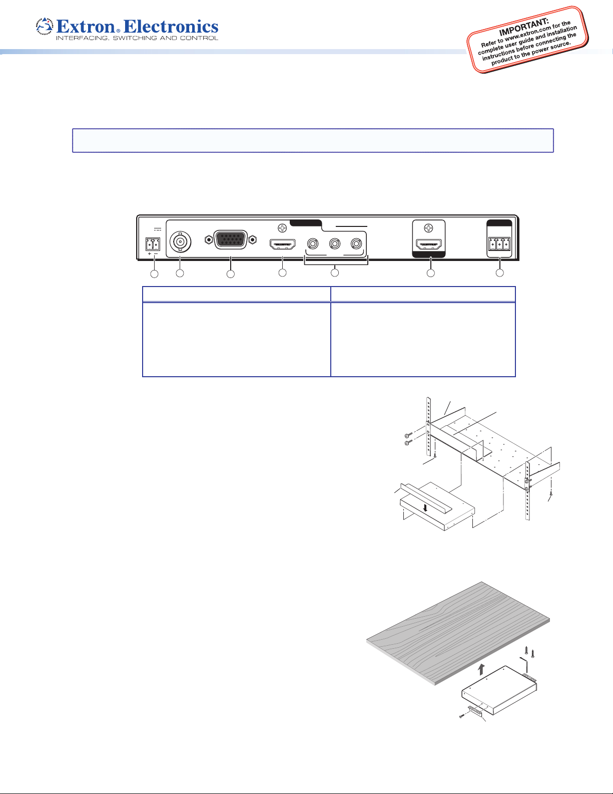
Power and video input connections Output and control connections
a DC power connector
b Composite video connector
c RGB, R-Y, Y, B-Y via 15-pin HD connector
d HDMI connector
e Audio 3.5 mm TRS (tip-ring-sleeve) connectors
23
23
2
3
INPUTS
INPUTS
1
4
1
DSC 301 HD
DSC 301 HD
23
23
AUDIO
AUDIO
5
f
HDMI connector
g
RS-232 captive screw connector
OUTPUT
OUTPUT
6
REMOTE
REMOTE
RS-232
RS-232
Tx Rx G
Tx Rx G
7
Mounting and Cabling
Step 1 — Mounting
Turn off or disconnect all equipment power sources and rack mount the
DSC 301 HD unit with either an optional shelf mounting brackets (RSU 126 or
129, RSB 126 or 129) or optional furniture mounting brackets (MBU 125); see
figures 1 and 2 at right. When rack mounting, an optional rack false face plate
(RFF 052) can be fitted on top of the low profile DSC, improving the overall look
within the rack.
Step 2 — Connecting inputs
Connect inputs from video sources to the applicable connectors marked “Inputs”:
b Composite video, c RGB, R-Y, Y, B-Y, d HDMI (with or without embedded
digital audio).
Connect inputs from analog audio sources to the TRS inputs e.
Step 3 — Connecting outputs
Connect a suitable output display device to the connector marked “Output”
(see f above) for HDMI output with embedded audio.
Step 4 — Connecting control devices
RS-232 — For serial RS-232 control, connect a host computer or control
system to the 3-pole captive screw connector g.
RS-232 protocol (default values): 9600 baud, 1 stop bit, no parity, 8 data bits,
no flow control.
USB — Connect a host computer or control system to the front panel mini USB
port for configuration and control via Extron Configurator software.
Step 5 — Connecting power
DC power connector — Plug in a 12 VDC, 1A max power source into this
2-pole captive screw connector a.
Figure 1. Rack mount
#8 Screw
(4) Places
Each Side
MBU 125
Mounting Bracket
Figure 2. Furniture Mount
Mounting Screws
(2) Places
Each Side
1
Page 2
DSC 301 HD • Setup Guide (Continued)
Front Panel Overview
1
Extron
Extron
CONFIG
CONFIG
132
132
4
HDCP
HDCP
INPUT
INPUT
OUTPUT
OUTPUT
MENU ENTER
MENU ENTER
ADJUST
ADJUST
DSC 301 HD
DSC 301 HD
2
a
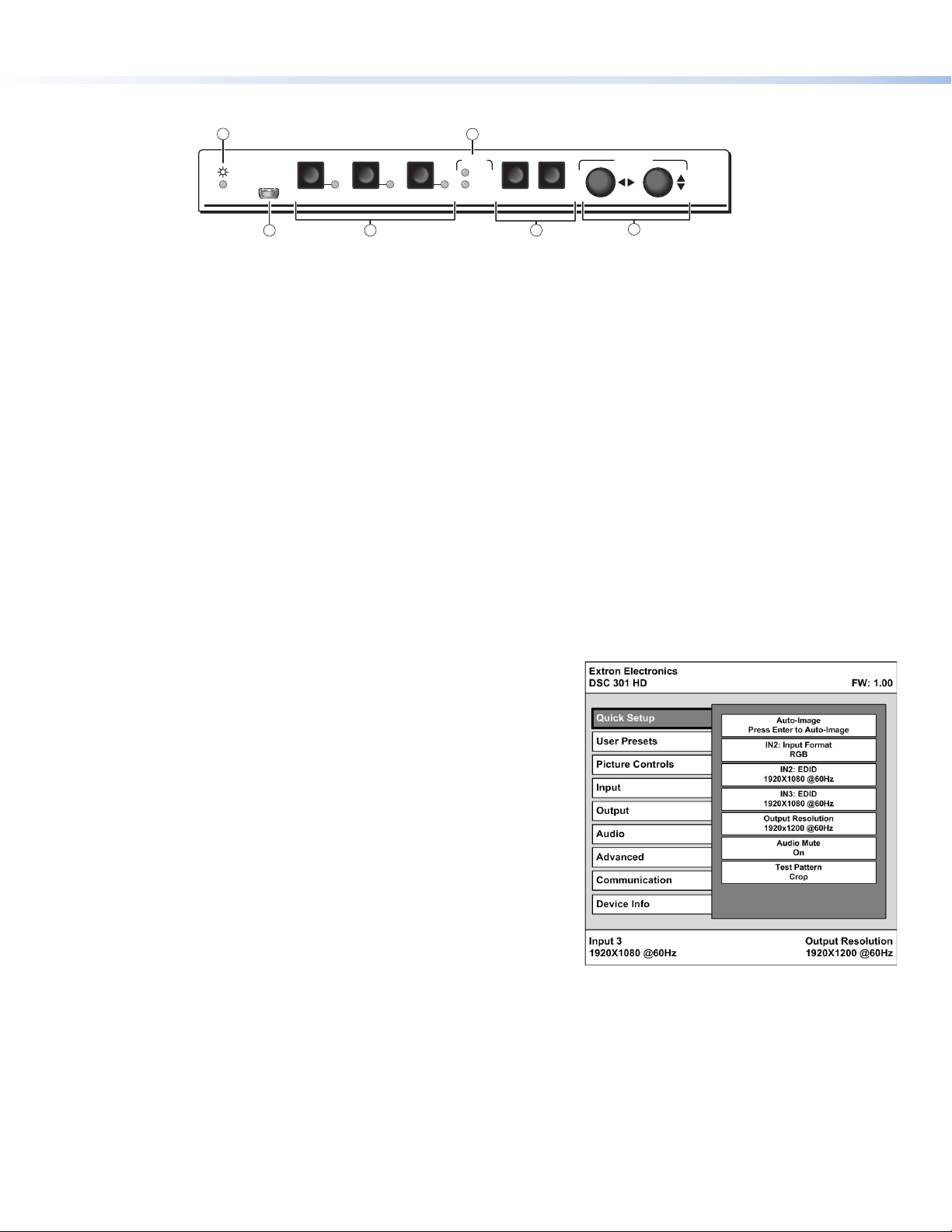
Status LED — This LED lights amber when there is power but no signal, and green when power and signal are both present.
b
Front panel mini USB configuration port — Connect a control system or computer to this mini USB port (cable not supplied), for
3
5
device configuration, control, and firmware upgrading.
c
Input selection buttons and LEDs (1-3) — Select/switch inputs; LEDs indicate which input is active (current input lights green).
d
HDCP content LEDs — These LEDs indicate HDCP status for input and output signals;
• Light green when an input or output signal is HDCP encrypted.
• Remain unlit when a current input or HDMI output is not HDCP encrypted.
• Flash amber when the video output has been disabled (such as when in sync mute of screen saver mode).
e
Menu navigation buttons (Menu, Enter) — These buttons allow navigation through the OSD menu system of the DSC 301 HD.
f
Adjust knobs — These are used with the menu navigation buttons to adjust the device settings and picture controls.
Setting the Front Panel Locks (Executive Modes)
The DSC 301 HD has three modes of front panel security lock that limit the operation of the unit from the front panel.
Executive mode 0 (disabled) — The front panel is fully unlocked. This is the default setting.
Executive mode 1 (enabled) — The front panel is completely locked. Can only be enabled and disabled using SIS commands, or
Extron Configurator software. See the online DSC 301 HD User Guide or the rear page of this guide for SIS commands.
Executive mode 2 (enabled) — The front panel is locked except for input switching.
Configuring the DSC 301 HD
DSC 301 HD devices can be configured through a host connected via RS-232 or USB and using Extron Configurator software or Extron
Simple Instruction Set (SIS) commands (see rear page for a selection of basic commands).
6
On-Screen Display (OSD) Menu System
The scaler has an OSD menu consisting of nine submenus that can be accessed
using the front panel Menu and Enter buttons. The Communication menu and the
Device Info menu are read-only menus. The menus are:
• Quick Setup • User Presets • Picture Controls • Input • Output
• Audio • Advanced • Communication • Device Info.
To use any menu:
1. Press the Menu button to access the main menu.
2. Rotate either Adjust knob to cycle through to the desired menu.
3. Press the Enter button to access the submenu.
4. Rotate either Adjust knob to cycle through the submenu to the
desired option.
5. Press the Enter button to adjust a submenu variable.
Using the OSD menu to configure the DSC 301 HD
z Use the Quick Setup menu to Auto-Image the current input, set video input format, input EDID settings, set output resolution,
audio mute and video test patterns.
z Use the User Presets menu to save the picture control adjustments to each input for later manual recall.
z Use the Picture Controls menu to adjust the image horizontal and vertical position and size, the brightness and contrast
settings, the color and tint levels, and the detail settings as needed.
z Use the Input menu to perform an Auto-Image on the current input, set the video input format and film mode, horizontal and
vertical start, the number of active horizontal pixels and vertical lines, set the total pixels and phase, set HDCP authorization to on or
off, and set the EDID for the current input.
z Use the Output menu to set output resolution, set the HDMI output format, set HDCP notification, and set the Accu-RATE Frame
Lock™ (AFL™) to on or off.
2
Page 3
z Use the Audio menu to set and control the
audio mute, the audio input format for the
selected input, and set the analog gain and
attenuation levels.
z Use the Advanced Configuration menu
to select a test pattern, adjust screen saver
settings, turn on or off Auto Image, set aspect
ratio (Fill or Follow), turn the auto memory on
or off, adjust the overscan settings, choose the
auto switch priorities, and reset the unit back to
factory defaults.
z Use the Communication menu to view the
RS-232 baud rate.
z Use the Device Info menu to view the status such as temperature, firmware build, input, output, AFL, HDCP, and display details.
This is a read-only menu.
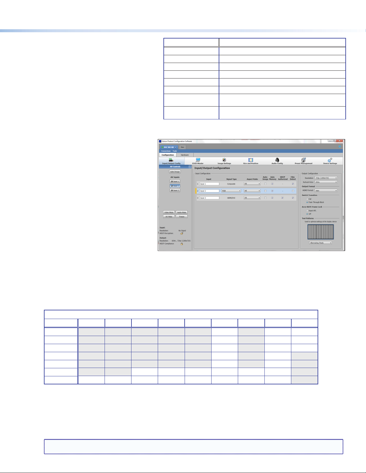
DSC 301 HD Configuration Software
To configure the unit using the DSC 301 HD
Configuration software, the software must be
installed (from the included DVD or from
www.extron.com) on a PC connected to the
DSC 301 HD via an RS-232 or via the front panel
USB config port. Installation creates a
C:\Program Files\Extron\DSC 301 HD
folder and installs the program, a help file, and an
uninstall utility. After installation, start the program
and either connect via the comm (RS-232) port or
by USB. For full instructions press <F1> or click on
Help>Contents.
Audio Input Format Details
None Mutes all audio for selected input
Analog TRS 1 Sets selected input to analog TRS 1 (default for input 1).
Analog TRS 2 Sets selected input to analog TRS 2 (default for input 2)
Analog TRS 3 Sets selected input to analog TRS 3.
LPCM-2Ch Digital Sets selected input to LPCM-2Ch digital audio (default for input 3).
Multi-Ch Digital Sets selected input to Multi-Ch digital audio.
LPCM-2Ch Auto (TRS 3) Sets selected input to use LPCM-2Ch digital audio (when present),
else use analog TRS 3.
Multi-Ch Auto (TRS 3) Sets selected input to use Multi-Ch digital audio (when present),
else use analog TRS 3.
Upgrading the Firmware
The onboard firmware of the DSC 301 HD unit can
be upgraded via the configuration software when
connected via the front panel USB port.
Alternatively upgrades can be made using the Extron Firmware Loader program, which is available online at www.extron.com.
Output Scaler Rates
Output rates can be set using the OSD menu or SIS commands. The table below gives the most commonly used rates and the
corresponding SIS variables. See rear page for SIS command input.
The command to set the output rate is
EX2!
RATE}, where
X2!
is the output scaler rate as given in the example table below (* = default).
See the DSC 301 HD User Guide (available at www.extron.com) for the full SIS and output scaler rate details.
SIS variable
Resolution 23.98 Hz 24 Hz 25 Hz 29.97 Hz 30 Hz 50 Hz 59.94 Hz 60 Hz 75 Hz
1024x768 19 20 21
1280x800 31 32 33
1280x1024 34 35 36
1680x1050 59 60
1920x1200 63 64
720p 68 69 70 71 72 73*
1080p 77 78 79 80 81 82 83 84
X2!
for EDID or output resolution/refresh rate combination (where
X2! = 10 through 92)
Output Rate Reset
If an output image cannot be displayed due to an incompatible output rate, the DSC 301 HD can be reset via the front panel to either
1024x768 @ 60 Hz or 720p @ 60 Hz.
To set the rate, or to toggle between 1024x768 @ 60 Hz and 720p @ 60 Hz:
Press and hold input buttons 1 and 3 simultaneously for approximately 3 seconds. The output rate becomes 1024x768 @ 60 Hz. Again
press and hold input buttons 1 and 3 simultaneously for another 3 seconds and the output rate becomes 720p @ 60 Hz.
NOTES: The output rate will subsequently toggle between 1024x768 @ 60 Hz and 720p @ 60 Hz every 3 seconds each time inputs 1
and 3 are simultaneously pressed and held for 3 seconds.
3
Page 4

DSC 301 HD • Setup Guide (Continued)
Basic SIS Commands Table
The DSC 301 HD can be configured with specific SIS commands via RS-232 or USB connection. This table lists a selection of the
commands. For a full list of SIS commands and variables see the DSC 301 HD User Guide, online at www.extron.com.
Command ASCII command
(host to scaler)
Select video and audio input
X!
! In
Audio input format — selects between analog (3.5 mm TRS) and digital (HDMI embedded) audio sources
Set to None
Set to Analog TRS 1
Set to Analog TRS 2
Set to Analog TRS 3
Set to LPCM-2Ch Digital
Set to Multi-Ch Digital
Set to LPCM-2Ch Auto
Set to Multi-Ch Auto
Execute Auto-Image
Disable auto switch mode
Set auto switch high to low (3 to 1)
Set auto switch low to high (1 to 3)
View auto switch mode
Set output scaler rate
View output scaler rate
Mute video to black
Mute video and output sync
Unmute video
Enable Executive mode 1
Enable Executive mode 2
Disable Executive mode
View front panel lock status
Set screen saver mode
View screen saver mode
Set screen saver time out duration
View screen saver time out duration
View screen saver status
Reset device to factory settings
Power save off
Power save on
View setting
NOTE: X! = Input number (1 – 3).
X2!
X2%
X3^
Extron Headquarters
+1.800.633.9876 (Inside USA/Canada Only)
Extron Europe
+31.33.453.4040
= Output scaler rate (see the resolution and refresh rate table on page 3 for details).
= Screen saver mode, (1 = black, 2 = blue)
X2*
= Screen saver time out duration in seconds; (1-500 in 1 second increments, default is 501 = never), 0 = Instant timeout
X3@
= Auto switch setting, (0 = manual, 1 = high to low, 2 = low to high)
= Power save setting, (0 = full power, 1 = low power state)
X3&
= Screen saver status (0 = active, 1 = no active input, timer running, output sync still active, 2 = No active input, timer expired, output sync disabled)
© 2013 Extron Electronics — All rights reserved. All trademarks mentioned are the property of their respective owners. www.extron.com
EIX!
EIX!
EIX!
EIX!
EIX!
EIX!
EIX!
EIX!
A Img
E
0AUSW
E
1AUSW
E
2AUSW
E
AUSW
EX2!
E
RATE
1B
2B Vmt2
B
0
1X Exe1
2X Exe2
0X Exe0
X 0] (or
EMX2%
E
MSSAV
ETX2*
E
TSSAV
E
SSSAV
E
ZXXX
E0PSAV} Psav0]
E1PSAV} Psav1] DSC enters low power mode. Exit using E0PSAV} command.
EPSAV}
Extron Asia
+65.6383.4400
Extron Japan
+81.3.3511.7655
*0AFMT
*1AFMT
*2AFMT
*3AFMT
*4AFMT
*5AFMT
*6AFMT
*7AFMT
}
}
}
}
RATE
}
SSAV
}
SSAV
}
}
}
}
}
}
}
}
}
}
}
}
}
}
4
Response
(scaler to host)
X!•
]
All
X!*0]
AfmtI
X!*1]
AfmtI
X!*2]
AfmtI
X!*3]
AfmtI
X!*4]
AfmtI
X!*5]
AfmtI
X!*6]
AfmtI
X!*7]
AfmtI
]
0]
Ausw
1]
Ausw
]
Ausw2
X3@]
X2!]
Rate
X2!]
]
Vmt1
]
]
Vmt0
]
]
]
1] or
X2%]
SsavM
X2%]
X2*]
SsavT
X2*]
X3&]
]
Zpx
X3^]
Extron China
+86.21.3760.1568
Extron Middle East
+971.4.2991800
Additional description
Selects video and audio from input X!.
Mutes all audio for input X!.
Selects analog TRS 1 for input X!. (default for input 1)
Selects analog TRS 2 for input X!. (default for input 2)
Selects analog TRS 3 for input X!.
Selects LPCM-2Ch digital audio for input X!. (default for input 3)
Sets EDID to LPCM-2Ch digital audio (valid for input 3 only).
Selects Multi-Ch digital audio for input X!.
Sets EDID to Multi-Ch digital audio (valid for input 3 only).
Selects auto detect audio for input X!.
Sets EDID to LPCM-2Ch (valid for input 3 only).
Selects auto detect audio for input X!.
Sets EDID to Multi-Ch (valid for input 3 only).
Executes Auto-Image on current input.
Manual input switching only.
Gives priority to highest numbered active input.
Gives priority to lowest numbered active input.
View current setting.
Select output resolution and refresh rate
View current output resolution and refresh rate
Mutes video and displays a black screen.
Mutes video and sync output.
Unmutes video.
Locks out entire front panel.
Allows input selection only.
Allows all front panel adjustments and selections.
Shows executive mode status.
2])
Sets the screen saver mode to
View current screen saver mode
Sets the screen saver time out duration to
(default: 501 = never).
View the screen saver time out duration
View the screen saver status
Resets all device settings to factory default.
DSC runs in full power mode (default).
View power save status.
X2!
X2%
(default: 1 = black).
X2%
.
X2*
X3&
.
Extron Korea
+82.2.3444.1571
Extron India
+91.80.3055.3777
.
X2!
X2*
seconds
.
.
68-2338-50
Rev. A
01 13
 Loading...