

Page 1
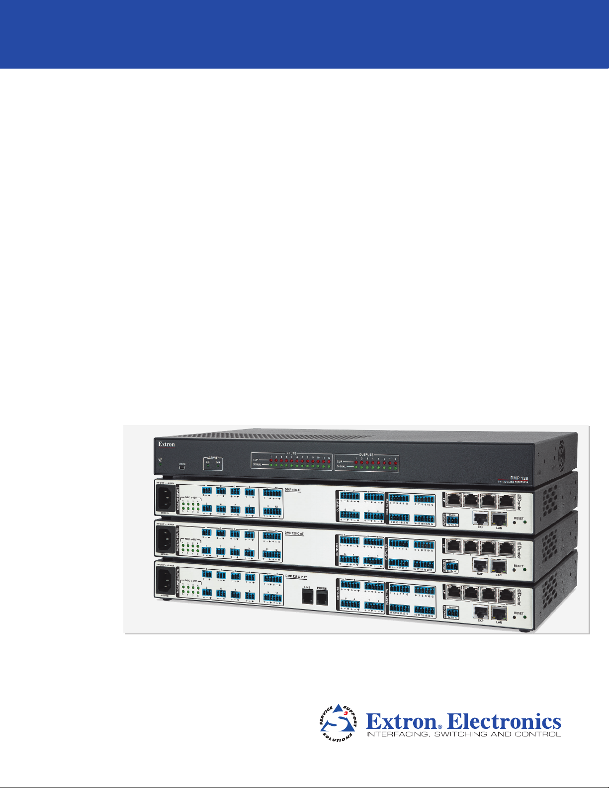
DMP 128
Digital Matrix Processor
User Guide
Audio Products
Mixers and Processors
68-2036-01 Rev. C
08 13
Page 2
Safety Instructions
Safety Instructions • English
WARNING: This symbol, , when used on the product, is intended to
alert the user of the presence of uninsulated dangerous voltage within
the product’s enclosure that may present a risk of electric shock.
ATTENTION: This symbol, , when used on the product, is intended to alert
the user of important operating and maintenance (servicing) instructions in the
literature provided with the equipment.
For information on safety guidelines, regulatory compliances, EMI/EMF
compatibility, accessibility, and related topics, see the Extron Safety and
Regulatory Compliance Guide, part number 68-290-01, on the Extron
website, www.extron.com.
Instructions de sécurité • Français
AVERTISSEMENT: Ce pictogramme, , lorsqu’il est utilisé sur le
produit, signale à l’utilisateur la présence à l’intérieur du boîtier du
produit d’une tension électrique dangereuse susceptible de provoquer
un choc électrique.
ATTENTION: Ce pictogramme, , lorsqu’il est utilisé sur le produit,
signale à l’utilisateur des instructions d’utilisation ou de maintenance
importantes qui se trouvent dans la documentation fournie avec le
matériel.
Pour en savoir plus sur les règles de sécurité, la conformité à la
réglementation, la compatibilité EMI/EMF, l’accessibilité, et autres sujets
connexes, lisez les informations de sécurité et de conformité Extron, réf. 68290-01, sur le site Extron, www.extron.fr.
Sicherheitsanweisungen • Deutsch
WARNUNG: Dieses Symbol auf dem Produkt soll den Benutzer darauf
aufmerksam machen, dass im Inneren des Gehäuses dieses Produktes
gefährliche Spannungen herrschen, die nicht isoliert sind und die einen
elektrischen Schlag verursachen können.
VORSICHT: Dieses Symbol auf dem Produkt soll dem Benutzer
in der im Lieferumfang enthaltenen Dokumentation besonders
wichtige Hinweise zur Bedienung und Wartung (Instandhaltung)
geben.
Chinese Simplified(简体中文)
警告: 产品上的这个标志意在警告用户该产品机壳内有暴露的危险
电 压 ,有 触 电 危 险 。
注意: 产品上的这个标志意在提示用户设备随附的用户手册中有
重要的操作和维护(维修)说明。
关于我们产品的安全指南、遵循的规范、
使用的特性等相关内容,敬请访问
安全规范指南,产品编号
68-290-01。
EMI/EMF 的兼容性、无障碍
Extron 网站 www.extron.cn,参见 Extron
Chinese Traditional(繁體中文)
警告: 若產品上使用此符號,是為了提醒使用者,產品機殼內存在著
可能會導致觸電之風險的未絕緣危險電壓。
注意 若產品上使用此符號,是為了提醒使用者。
有關安全性指導方針、法規遵守、EMI/EMF 相容性、存取範圍和相關主題的詳細
資訊,請瀏覽 Extron 網站:www.extron.cn,然後參閱《Extron 安全性與法規遵
守手冊》,準則編號 68-290-01。
Japanese
警告: この記 号 が製品上に表示されている場合は、筐体内に絶縁されて
いない高電圧が流れ、感電の危険があることを示しています。
注意: この記号 が製品上に表示されている場合は、本機の取扱説明書に
記載されている重要な操作と保守(整 備)の指示についてユーザーの
注意を喚起するものです。
安全上のご注意、法規厳守、EMI/EMF適合性、その他の関連項目に
つ い て は 、エク スト ロ ン の ウ ェ ブ サ イト www.extron.jp より
『Extron Safety and Regulatory Compliance Guide 』 (P/N 68-290-01) をご覧ください。
Weitere Informationen über die Sicherheitsrichtlinien, Produkthandhabung,
EMI/EMF-Kompatibilität, Zugänglichkeit und verwandte Themen finden Sie
in den Extron-Richtlinien für Sicherheit und Handhabung (Artikelnummer 68290-01) auf der Extron-Website, www.extron.de.
Instrucciones de seguridad • Español
ADVERTENCIA: Este símbolo, , cuando se utiliza en el producto,
avisa al usuario de la presencia de voltaje peligroso sin aislar dentro
del producto, lo que puede representar un riesgo de descarga
eléctrica.
ATENCIÓN: Este símbolo, , cuando se utiliza en el producto, avisa
al usuario de la presencia de importantes instrucciones de uso
y mantenimiento recogidas en la documentación proporcionada
con el equipo
Para obtener información sobre directrices de seguridad, cumplimiento
de normativas, compatibilidad electromagnética, accesibilidad y temas
relacionados, consulte la Guía de cumplimiento de normativas y seguridad de
Extron, referencia 68-290-01, en el sitio Web de Extron, www.extron.es.
.
Korean
경고: 이 기호 , 가 제품에 사용될 경우, 제품의 인클로저 내에 있는
접지되지 않은 위험한 전류로 인해 사용자가 감전될 위험이 있음을
경고합니다.
주의: 이 기호 , 가 제품에 사용될 경우, 장비와 함께 제공된 책자에 나와
있는 주요 운영 및 유지보수(정비) 지침을 경고합니다.
안전 가이드라인, 규제 준수, EMI/EMF 호환성, 접근성, 그리고 관련
항목에 대한 자세한 내용은 Extron 웹 사이트(www.extron.co.kr)의
Extron 안전 및 규제 준수 안내서, 68-290-01 조항을 참조하십시오.
Page 3

FCC Class A Notice
This equipment has been tested and found to comply with the limits for a Class A digital device,
pursuant to part15 of the FCC rules. The ClassA limits provide reasonable protection against harmful
interference when the equipment is operated in a commercial environment. This equipment generates,
uses, and can radiate radio frequency energy and, if not installed and used in accordance with the
instruction manual, may cause harmful interference to radio communications. Operation of this
equipment in a residential area is likely to cause interference; the user must correct the interference at
his own expense.
NOTE: For more information on safety guidelines, regulatory compliances, EMI/EMF compatibility,
accessibility, and related topics, see the “
Guide” on the Extron website.
Extron Safety and Regulatory Compliance
Copyright
© 2013 Extron Electronics. All rights reserved.
Trademarks
All trademarks mentioned in this guide are the properties of their respective owners.
The following registered trademarks
®
, registered service marks
RGBSystems, Inc. or Extron Electronics:
Registered Trademarks
AVTrac, Cable Cubby, CrossPoint, eBUS, EDID Manager, EDID Minder, Extron, Flat Field, GlobalViewer, Hideaway, Inline, IPIntercom, IPLink,
Key Minder, LockIt, MediaLink, PlenumVault, PoleVault, PowerCage, PURE3, Quantum, SoundField, SpeedMount, SpeedSwitch, System
Integrator, TeamWork, TouchLink, V-Lock, VersaTools, VN-Matrix, VoiceLift, WallVault, WindoWall, XTP and XTP Systems
(SM)
Registered Service Mark
AAP, AFL (Accu-Rate Frame Lock), ADSP (Advanced Digital Sync Processing), AIS (Advanced Instruction Set), Auto-Image, CDRS (Class D
Ripple Suppression), DDSP (Digital Display Sync Processing), DMI (Dynamic Motion Interpolation), DriverConfigurator, DSPConfigurator, DSVP
(Digital Sync Validation Processing), FastBite, FOXBOX, IP Intercom HelpDesk, MAAP, MicroDigital, ProDSP, QS-FPC (QuickSwitch Front Panel
Controller), Scope-Trigger, SIS, Simple Instruction Set, Skew-Free, SpeedNav, Triple-Action Switching, XTRA, ZipCaddy, ZipClip
: S3 Service Support Solutions
Trademarks
(SM)
, and trademarks
(®)
(™)
(TM)
are the property of
Page 4
Conventions Used in this Guide
Notifications
The following notifications are used in this guide:
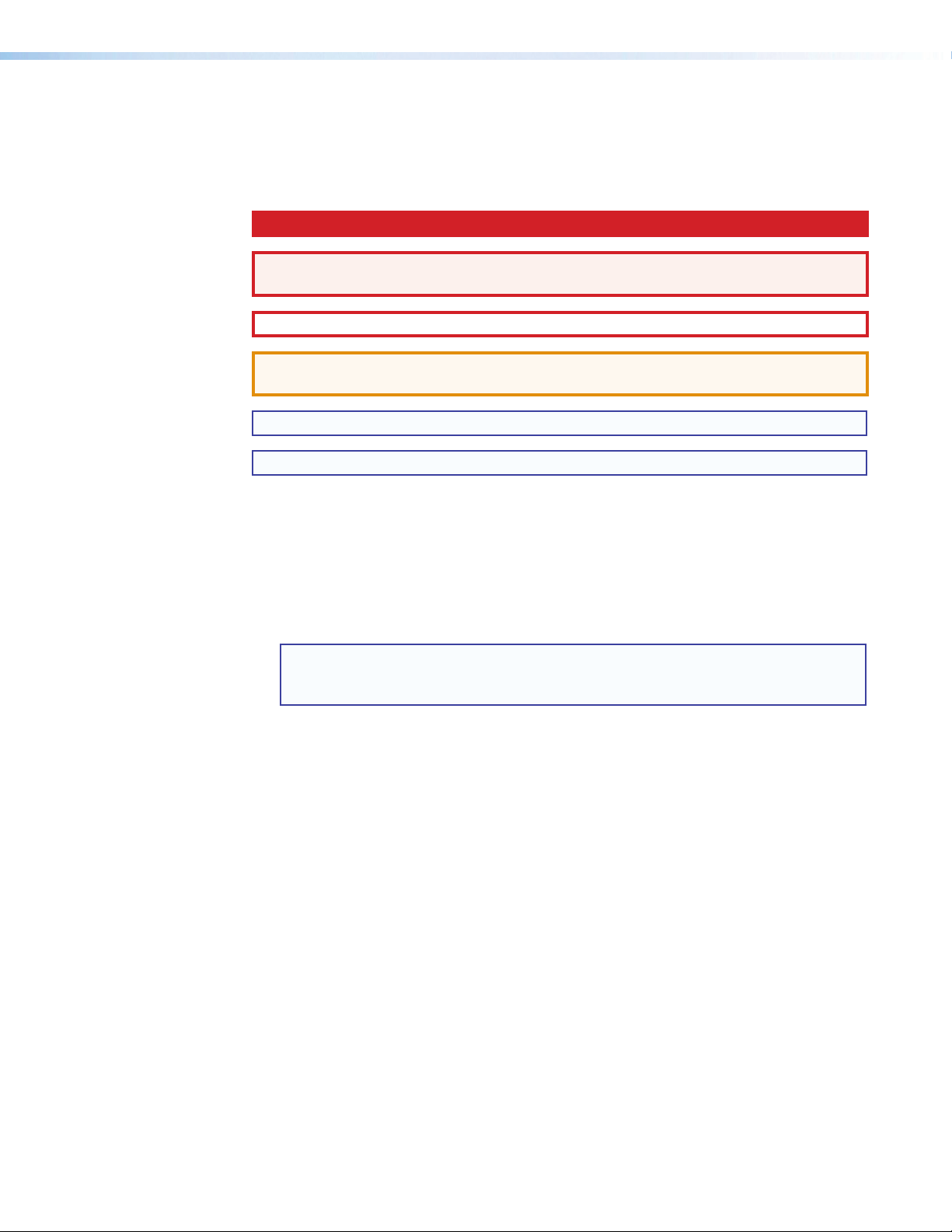
DANGER: A danger indicates a situation that will result in death or severe injury.
WARNING: A warning indicates a situation that has the potential to result in death or
severe injury.
CAUTION: A caution indicates a situation that may result in minor injury.
ATTENTION: Attention indicates a situation that may damage or destroy the product or
associated equipment.
NOTE: A note draws attention to important information.
TIP: A tip provides a suggestion to make working with the application easier.
Software Commands
Commands are written in the fonts shown here:
^AR Merge Scene,,Op1 scene 1,1 ^B 51 ^W^C
[01] R 0004 00300 00400 00800 00600 [02] 35 [17] [03]
Computer responses and directory paths that do not have variables are written in the font
shown here:
Variables are written in slanted form as shown here:
Selectable items, such as menu names, menu options, buttons, tabs, and field names are
written in the font shown here:
Specifications Availability
Product specifications are available on the Extron website, www.extron.com.
E X! *X1&* X2)* X2#* X2! CE}
NOTE: For commands and examples of computer or device responses mentioned
in this guide, the character “0” is used for the number zero and “O” is the capital
letter “o.”
Reply from 208.132.180.48: bytes=32 times=2ms TTL=32
C:\Program Files\Extron
ping xxx.xxx.xxx.xxx —t
SOH R Data STX Command ETB ETX
From the File menu, select New.
Click the OK button.
Page 5

Contents
Introduction .......................................................... 1
About This Guide ................................................ 1
About the DMP128 Digital Matrix Processor ...... 1
Features ............................................................. 1
DMP128 Application Diagram ............................ 4
Installation ............................................................. 5
Mounting the DMP128 ...................................... 5
DMP128 Models ............................................... 5
Hardware Configuration ...................................... 5
Rear Panel Features and Cabling ........................ 6
USB Configuration Port (Front Panel) .................. 9
Front Panel Indicators ......................................... 9
Reset Actuator and LED ................................... 10
Hardware Reset Modes: ............................... 10
Digital I/O Ports ............................................ 11
DMP Software ..................................................... 12
Software Control............................................... 12
Windows-based Program Control ..................... 13
Installing the DSP Configurator Program ....... 13
Installing the USB Driver ............................... 15
DSP Configurator Program Basics .................... 16
Starting the Program .................................... 16
Using the Program ........................................ 16
Navigation .................................................... 20
DSP Configurator Toolbar Menus .................. 21
Presets Drop-down ...................................... 26
Mode Buttons .............................................. 26
Audio Level, Mix-point, Processing Blocks,
and Signal Chains ............................................ 27
Level Control Blocks ..................................... 28
Processor Blocks.......................................... 28
Mic/Line Input Signal Chain Controls ................ 30
Gain Control (GAIN) ...................................... 30
Filter (FILT) .................................................... 30
Acoustic Echo Cancellation (AEC) ................ 40
Advanced AEC Controls ............................... 43
Dynamics (DYN)............................................ 44
Delay (DLY) ................................................... 49
Ducking ....................................................... 50
Ducker Tutorials ............................................ 53
Automix (AM) ................................................ 54
Pre-mixer Gain (GAIN) .................................. 57
Telephone RX (DMP128CP and
DMP128CPAT only) ................................. 58
Line Output Channels ....................................... 58
Post-mixer Trim Control (TRIM) .................... 58
Loudness (LOUD) ......................................... 58
Delay Block (DLY) ........................................ 61
Filter Block (FILT) .......................................... 61
Dynamics Block (DYN) ................................. 61
Volume Control (VOL) .................................. 62
Telephone TX (DMP128CP and
DMP128CPAT only) ................................. 62
Virtual Bus Returns ........................................... 63
Virtual Bus Returns, A-D ............................... 63
Virtual Bus Returns, E-H ............................... 68
Output Mix Matrix ............................................. 69
Mix-point Behavior: ....................................... 71
Mix-point Examples ...................................... 73
Virtual Send Bus Mix Matrix .............................. 76
Expansion Outputs Mix Matrix .......................... 78
Extron EXP Bus ................................................ 79
Connecting the EXP Ports ............................ 79
Using the Expansion Bus .............................. 80
Device Manager ............................................... 81
AT (Dante) Bus ................................................ 81
Group Masters ................................................. 82
Group Members ........................................... 82
Grouped Controls ......................................... 82
Configuring a Group Master .......................... 84
Deleting a Group Master ............................... 85
Viewing and Using a Group Master ............... 85
Add a Group ................................................. 85
Tools ............................................................. 86
Soft Limits .................................................... 87
DigitalI/OPorts ................................................ 88
Reinitialize Digital I/O ..................................... 89
Emulate Mode and Live Mode .......................... 89
Synchronizing: Pull from or Push
to the Device ............................................... 89
Selecting Live Mode and Pushing
or Pulling Data ............................................. 90
Presets ............................................................. 93
Previewing and Recalling a Preset ................ 93
Building a Preset ........................................... 94
Managing Presets ......................................... 95
Presets: Pull, Push, or Create Live ................ 96
Protected Configuration .................................... 96
Save Protected Configuration ....................... 96
Recall Protected Configuration...................... 96
Change PIN .................................................. 96
vDMP128 • Contents
Page 6

DSP Configurator Windows Menus .................. 97
Keyboard Navigation .................................... 97
Optimizing Audio Levels ................................. 100
About Setting Gain Structure ...................... 101
Setting Input Gain ....................................... 102
Setting a Nominal Output Level................... 102
Adjusting Trim ............................................. 103
Adjusting Pre-mixer Gain ............................ 103
Setting Output Gain Structure ..................... 103
Setting Mic/Line Input and Mix Levels ......... 104
Adjusting Trim ............................................. 104
Setting Volume Control for the
Amplifier Stage .......................................... 104
Signal Path Building Blocks ............................ 105
Adding a Building Block .............................. 107
Organize Building Blocks ............................ 109
Dante Installation and Operation
(AT Models Only) ............................................... 112
DMP128AT Bus ............................................ 112
Dante Controller Software Installation ............. 113
Dante Network Audio Setup ....................... 113
Dante Device Discovery .............................. 115
Creating a Physical Dante Network ................. 116
Basic Configuration .................................... 116
Redundant Configuration ............................ 117
Managing Network Traffic ........................... 117
Dante Controller Configuration ........................ 118
Start Dante Controller ................................. 118
Rename a Dante Device ............................. 120
AT Expansion Bus Organization .................. 120
Rename an Input or Output ........................ 121
Selecting Inputs and Outputs for Dante .......... 122
DMP128PAT Bus Outputs ........................ 122
DMP128PAT Expansion Bus (AT Inputs) ... 123
Signal Routing with Dante ............................... 124
Using the Extron Expansion Bus
with DMP128AT Devices ............................. 125
Viewing AT Channels with AT Meters .............. 125
Telephone Interface ......................................... 126
Telephone Configuration ................................. 126
Telephone Dialer ............................................. 127
Third Party Control of the Phone Dialer ........... 128
SIS Programming and Control ...................... 129
Connection Options ........................................ 129
RS-232 Port ............................................... 130
USB Port (Front Panel) ................................ 130
Ethernet (LAN) Port ..................................... 130
Verbose Mode ............................................ 131
Host-to-device Communications .................... 132
DMP128-initiated Messages ...................... 132
Password Information ................................. 132
Using the Command and
Response Tables ....................................... 132
Symbol definitions ...................................... 133
Error Responses ......................................... 133
Simple Control Port Commands -
Telnet and Web-browser Accessible .......... 134
Command and Response Tables .................... 135
Basic SIS Commands ................................. 135
DSP SIS Commands .................................. 141
Symbol Definitions ...................................... 142
Special Characters ..................................... 142
Setting Audio Levels ................................... 148
HTML Operation ............................................... 155
Download the Startup Page ............................ 155
Status Tab ...................................................... 157
System Status Page ................................... 157
Configuration Tab ........................................... 157
System Settings Page ................................ 157
Passwords Page......................................... 160
Firmware Upgrade Page ............................. 161
File Management Tab ..................................... 164
File Management Page ............................... 164
Special Characters ......................................... 164
Reference Information .................................... 165
MountingtheDMP128 .................................. 165
Tabletop Use .............................................. 165
UL Rack Mounting Guidelines ..................... 165
Rack Mounting ........................................... 166
Table or Wall Mounting ................................ 167
Firmware Loader ............................................ 168
DMP128 Hardware Reset Modes .................. 169
DSP SIS Commands for Mix-point Level
and Mute Control .......................................... 170
Selecting Mix-points ................................... 171
Signal Routing ............................................ 171
Setting Audio Levels ................................... 172
SIS Command and Response Table
for DSP Mix-point and Level Control .......... 173
SIS Command Mix-points ............................... 174
Output Mixer .............................................. 175
Virtual Sends Bus Mix Matrix ...................... 185
EXP Outputs .............................................. 195
DMP128 • Contents vi
Page 7

Introduction
This section describes this user guide and the DMP128, including:
• About This Guide
• About the DMP128 Digital Matrix Processor
• Features
• DMP128 Application Diagram
About This Guide
This guide contains installation, configuration, and operating information for the
ExtronElectronicsDMP128ProDSP Digital Matrix Processor, software controlled digital
audio processor.
In this manual, the DMP128 may also be referred to as “the mixer” or “device.”
About the DMP128 Digital Matrix Processor
The Extron DMP128 Digital Matrix Processor is a 12x8 audio mixer featuring
ExtronProDSP, automixing, and I/O expansion capabilities, and is available with
AEC - acoustic echo cancellation plus Dante™ audio networking. The DMP128 offers
a configuration approach to DSP to simplify mixing, routing, conferencing, and room
optimization. Quick and intuitive configuration using the DSP Configurator™ Software allows
DMP128 installation in very little time, with easy-to-learn adjustments heard in real-time.
A digital audio expansion port allows two DMP128 units to be linked together to expand
input and output signal management and routing capabilities. The DMP128 is ideal for
presentation and conferencing applications in boardrooms, courtrooms, and conference
centers that require advanced matrix mixing with DSP.
The DMP128 has no front panel controls. All configuration is performed using the
ExtronDSPConfigurator program from a host computer via any of the communication
ports; RS-232, USB, or Ethernet (high-speed ports recommended). Signal presence and
clip LEDs for the twelve input channels and eight output channels are on the front panel.
Features
• Six models with 12 mic/line inputs, 8 outputs and Extron EXP expansion bus
include:
• DMP 128 — 12x8 ProDSP processor base unit
• DMP 128 C — 12x8 ProDSP processor with AEC
• DMP 128 AT — 12x8 ProDSP processor with Dante
• DMP 128 C AT — 12x8 ProDSP processor with AEC and Dante
• DMP 128 C P — 12x8 ProDSP processor with AEC and Phone (POTS) interface
• DMP 128 C P AT — 12x8 ProDSP processor with AEC, Phone (POTS) interface,
and Dante
DMP128 • Introduction 1
Page 8

• Inputs — Twelve balanced or unbalanced mic/line level on 3.5 mm, 3-pole and
6-pole captive screw connectors, eight with phantom power.
• Outputs — Eight balanced or unbalanced line level on 3.5 mm, 6-pole captive screw
connectors.
• Eight channels of acoustic echo cancellation (AEC) — The DMP128 C models
include eight independent channels of high performance AEC, as well as selectable
noise cancellation. Extron AEC features advanced algorithms that deliver fast echo
canceler convergence for optimal intelligibility in situations that challenge AEC
performance, including double-talk, and the use of wireless microphones at the near
end.
• Dante™ Audio Networking — Dante equipped DMP128PAT models provide
scalable audio transport over a local area network using standard Internet protocols.
Each DMP128PAT sends out 24 channels of 24-bit/48 kHz digital audio and can
receive 56 channels over the network. A built-in four-port Gigabit switch provides
direct interconnection of multiple DMP128PAT units to create larger, cost-effective
audio matrixes. Both Dante and the DMP128PAT processor four-port switch are
AVB - Audio Video Bridging ready. Dante is a trademark of Audinate® Pty Ltd.
• Digital audio expansion port for linking two DMP128 units — An expansion
port allows any two DMP128 models to be linked together via a single shielded
CAT6 cable. This allows eight matrix mixes of the inputs, plus eight virtual paths to be
sent and received between units.
• Automixer with eight gate groups — The DMP128 features an automixer with
advanced features for managing signal levels from multiple microphones. The
automixer includes a gating mode that automatically gates channels on or off, as well
as a gain sharing mode that maintains the overall system gain based on the number
of active mics.
• ProDSP audio signal processing — The DMP128 features 32/64-bit floating point
audio DSP processing, which maintains very wide dynamic range and audio signal
transparency, to simplify management of gain staging while reducing the possibility of
DSP signal clipping.
• 48-volt phantom power — The DMP128 is equipped with selectable 48-volt
phantom power for the first eight inputs, allowing the use of condenser microphones.
• 24-bit/48 kHz analog-to-digital and digital-to-analog converters — Fully
preserve the integrity of the original audio signal.
• Fixed, low latency DSP processing — Input to output latency is low within
the DMP128 and stays constant, regardless of the number of active channels or
processes. While latency increases marginally on channels with AEC enabled, overall
latency remains low. Fixed latency processing keeps audio in sync with video, and
prevents distractions to presenters or performers resulting from delayed live audio.
• DSP Configurator Software — A powerful yet user-friendly PC-based software
tool for managing all audio operations of the DMP128. It enables complete setup
and configuration of digital audio processing tools on the ProDSP platform, as well as
routing and mixing.
• Intuitive Graphical User Environment — The DSP Configurator Software features
a graphical user environment that offers a clear view of all input and outputs, audio
processing blocks, routing, mix-points, and virtual routing in a single screen. This
allows a designer or installer to quickly view an audio configuration without having to
access multiple dialog boxes or menus.
DMP128 • Introduction 2
Page 9

• Device Manager — Device Manager in the DSP Configurator Software enables
easy configuration of multiple Extron DSP products, including two linked DMP128
processors, by toggling between graphical user environments for each unit.
Processors can be grouped into folders for organizing as separate rooms or buildings.
Settings for multiple Extron DSP products in the Device Manager can be saved to a
single file.
• Flexible control options — The DMP128 can be controlled using the DSP
Configurator Software and a PC connection to the Ethernet port, the RS-232 serial
port, or the USB 2.0 port on the front panel. The DMP128 can also be controlled
through a control system with Extron Simple Instruction Set (SIS)™ commands, and
by accessing the internal Web pages.
• Copy and paste for processing blocks — To help speed audio system design
and setup, parameter settings can be quickly copied between individual processing
blocks or identical groups of blocks within the graphical user environment, using
conventional cut-and-paste commands.
• Building Blocks processor settings — A collection of pre-designed processor
settings optimized for a specific type of input or output device, such as microphones
and Extron speakers, with preset levels, filters, dynamics, and more. Flexible building
blocks are available on each I/O strip and allow system designers to fully customize
and save their own building blocks, further streamlining audio system design and
integration.
• Live and Emulate operation modes with configuration file saving — Live
mode allows integrators to connect to the DMP128 and make live parameter
adjustments while hearing or metering them in real-time. This avoids the need to
compile and upload a configuration file to the DSP. Emulation mode allows settings to
be configured offline, then uploaded to the DMP128. The software also downloads
configuration files from the mixer for archiving. Settings for two DMP128 processors
linked together can be saved to a single configuration file.
• 32 DSP Configurator presets — Using the DSP Configurator Software, any
parameters for DSP processing, levels, or audio routing can be saved as presets.
These settings can be saved for the entire system, or any selected group of inputs,
outputs, mix-points, and DSP blocks.
• 20 digital I/O ports for remote control or feedback — Twenty configurable digital
I/O ports are provided, so that the DMP128 can be programmed to sense and then
respond to external triggers such as mic activation, muting, and recall of presets.
• Triple matrix design provides output, virtual, and expansion routing options —
Employs a triple matrix design that offers substantial flexibility in routing, mixing, and
processing audio input sources. An output matrix allows any of the twelve inputs to
be mixed to any or all eight outputs. If desired, any of the inputs can first be directed
into a virtual matrix, which routes the inputs to eight virtual buses, before being mixed
back into the output matrix. Virtual buses allow inputs to be processed together as
a group. When two DMP128 processors are linked together via the expansion ports
over shielded CAT 6 cable, inputs and virtual buses of one unit can be routed to the
other processor through an expansion matrix, for additional processing or matrix
mixing into the outputs.
• Group masters — The DMP128 provides the capability to consolidate gain or mute
control throughout the system. Gain or mute controls can be selected and added to a
group master, which can then be controlled by a single master fader or mute control.
Each group master can have up to 16 members, and up to 32 group masters can be
created.
DMP128 • Introduction 3
Page 10
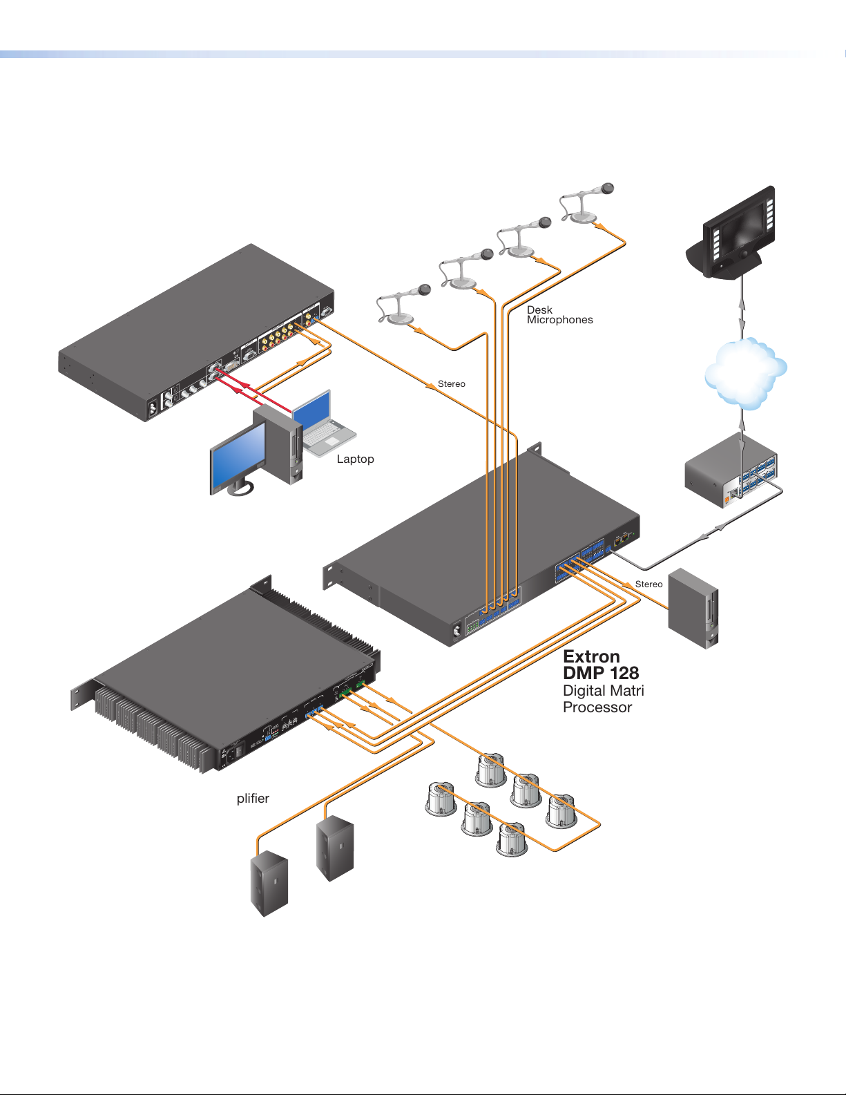
DMP128 Application Diagram
Speakers
RS-232
OUTPUT
A
B
L
L R
6
R
8
4 5
7
3
AUDIO INPUT
2
1
L
OUTPUT
R
RGB
LISTED
1T23
U S
I.T.E.
Y, B-Y, R-Y
C
6
8
DVI
RGB
7
RGB
3
YC
R-Y
1
VID
5
B-Y
I
Y
N
VID
100-240V 50-60Hz
4
P
U
2
T
Extron
IN1508
Scaling Presentation
Switcher
PC
Laptop
Stereo
Desk
Microphones
ON
OFF
DISPLAY
MUTE
SCREEN
UP
SCREEN
DOWN
Extron
TLP 700TV
7" TouchLink
Tabletop
Touchpanel
Extron
IPL 250
IP Link Ethernet
Control
Processor
™
Ethernet
TCP/IP
Network
COM1
RT SC TS
TXRX
INPUT
3 4
2
LAN
1
POWER
12V
500mA
MAX
VCR
DVD
DOC
CAM
LAPTOP
PC
2
RELAY
1
2
IR
1
COM 2
RX
4
RELAY
TX
G S G
3
S
IR
4
3
COM 3
TXRX
G S G
S
LAN
RESET
EXP
DIGITAL I/O
RS-232
8 9 10
6 7
Tx Rx
5
1617 1819 20
4
15
14
1 2 3
3 4
13
12
11
1 2
8
7
O
U
T
P
5 6
U
T
9 10
4
3
11
2
8
1
7
6
MIC/LINE INPUTS
5
MIC
+48V
4
100-240V 0.6A
3
8
2
7
1
6
5
50/60 Hz
XPA 2003C -70V
70V
3
CLASS 2 WIRING
OUTPUTS
4/8
HPF
1 2
CH 3
80 Hz
OFF
INPUTS
3
2
1
LEVEL
3
2
0
1
0
LIMITER/
0
REMOTE
PROTECT
TIMER DISABLE
STANDBY
SIGNAL
1.3A MAX
100-240V 50/60 Hz
GREEN - ACTIVE
AMBER - STANDBY
Listed
17TT
AUDIO/VIDEO
APPARATUS
S
12
Extron
DMP 128
Digital Matrix
Processor
Stereo
Recording Device
RS-232
Extron
XPA 2003C 70V
Combo Power Amplifier
Extron
SI 26CT
Two-Way Ceiling
Extron
Speakers
SI 28
Surface-Mount
DMP128 • Introduction 4
Page 11

Installation
This section describes the installation of the DMP128, including:
• Mounting the DMP128
• DMP128 Models
• Hardware Configuration
• Rear Panel Features and Cabling
• USB Configuration Port (Front Panel)
• Front Panel Indicators
• Reset Actuator and LED
Mounting the DMP128
The 1U high, full rack width, 8.5-inch deep DMP128 Digital Matrix Processor can be:
• Set on a table,
• Mounted on a rack shelf,
• Mounted under a desk or tabletop.
For detailed mounting options and UL rack mounting guidelines, (see
MountingtheDMP128 on page165).
DMP128 Models
There are six models of the DMP128 available. Each model has a different feature set for
various applications.
DMP128 Model Matrix
The following feature matrix provides a breakdown of the various DMP128 model
variations. Where differences occur in operation, they are noted in the text.
DMP128 12x8 ProDSP Processor
DMP128 C 12x8 ProDSP Processor with AEC
DMP128 AT 12x8 ProDSP Processor with Dante Interface
DMP128 C AT 12x8 ProDSP Processor with AEC, EXP Bus, and Dante Interface
DMP128 C P 12x8 ProDSP Processor with EXP Bus, AEC, and Telephone modem
DMP128 C PAT 12x8 ProDSP Processor with AEC, Telephone modem, EXP Bus, and
Hardware Configuration
The DMP128 does not have physical controls for configuration or operation.
The DMP128 has several front and rear panel operational indicators and a rear panel
reset button for hardware resets outlined in the following pages.
Model Description
Dante Interface
DMP128 • Installation and Operation 5
Page 12
Rear Panel Features and Cabling
k
DMP 128 C AT
Audio Input Wiring
100-240V ~ 0.6A MAX
50/60 Hz
MIC +48V
1234
MIC/LINE INPUTS
5678
1
4 1
910
DMP 128 C AT
8
11 1273625
PHONELINE
234
56 78
OUTPUTS
1 2345G 6
78910 G
DIGITAL I/O
11 12 13 14 15 G1617181920G
1234
RS-232
Tx Rx G
REMOTE AT
efgh jiab cdl
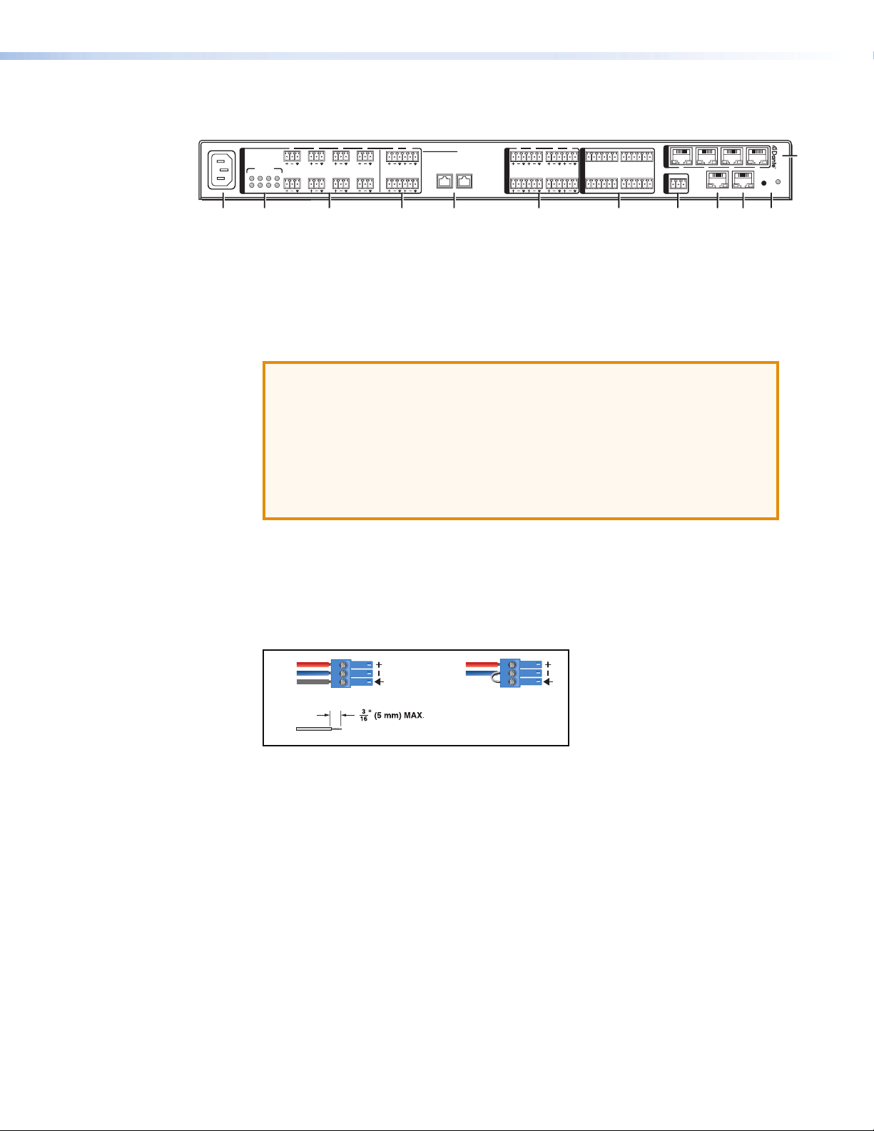
Figure 1. DMP128 Rear Panel (DMP128CPAT shown)
a Power connector — IEC power connector 100 to 240 VAC, 50 — 60 Hz
b Phantom Power indicators (MIC +48V) — LEDs light when +48V phantom
power is placed on the corresponding mic/line input. Phantom power voltage is not
adjustable and is only available to Micinputs 1 through 8.
ATTENTION:
• Condenser microphones require phantom power.
Dynamic microphones do not require power.
Never set an unbalanced dynamic microphone to +48V. Doing so may
damage the microphone.
• For condenser microphones, verify it safely operates at +48 VDC.
• When a line level source is connected, be certain the +48V phantom
power is off (cleared).
c Mic/Line 1-8 input connectors — Eight 3-pole 3.5 mm captive screw connectors
accept balanced or unbalanced mono mic or line level signals and provide phantom
power. Mic/line inputs provide gain settings to accommodate consumer (– 10dBV)
and professional (+ 4dBu) operating line level sources, plus mic level sources. Up to
eight mono mics or line inputs, balanced or unbalanced in any combination can be
connected to these inputs, (see figure 2).
RESET
LAN
EXP
Tip
Ring
Sleeve
Balanced Input
Tip
Sleeve
Unbalanced Input
Do not tin the wires!
Figure 2. Balanced or Unbalanced Mic and Line Input Wiring
d Mic/Line 9-12 input connectors — Four 6-pole 3.5 mm captive screw connectors
accept balanced or unbalanced mono mic or line level signals. Mic/line inputs provide
gain settings to accommodate consumer (– 10dBV) and professional (+ 4dBu) line
level sources, plus mic level sources. Up to four mono mics or line inputs (or two
stereo line inputs), balanced or unbalanced in any combination can be connected to
these inputs.
DMP128 • Installation and Operation 6
Page 13
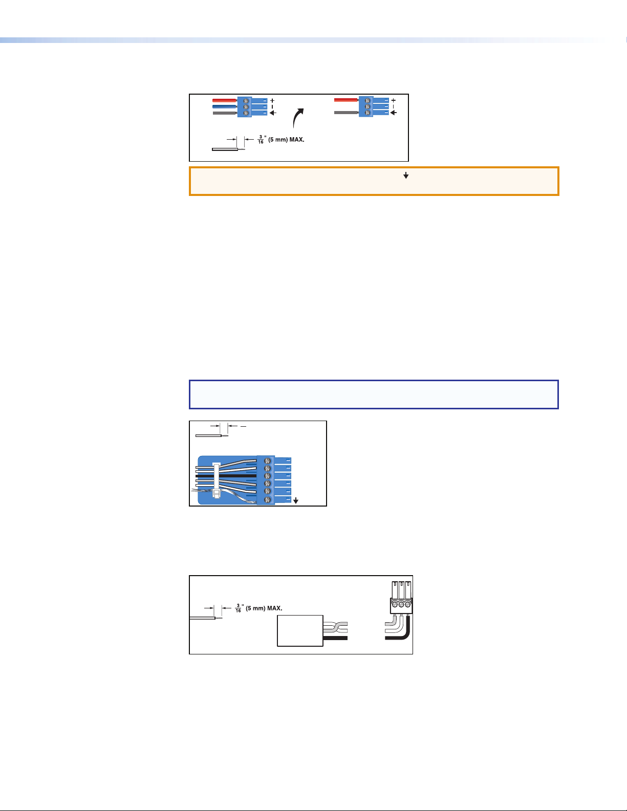
e Mono output connectors — Four 6-pole 3.5 mm captive screw connectors provide
Audio Output Wiring
Audio Input Wiring
Slee
Unbalanced Input
Tip
Sleeve
Balanced Input
Tip
Sleeve
Ring
Do not tin the wires!
3 "
RxTx G
up to eight balanced or unbalanced connections for mono line level output signals.
Tip
Ring
ve
Balanced Output
Do not tin the wires!
Tip
NO Ground Here
Sleeve
Unbalanced Output
ATTENTION: Connect the sleeve to ground ( ). Connecting the sleeve only to
a negative(– ) terminal will damage the audio output circuits.
Figure 3. Output Connector Wiring
f Digital I/O output connectors — Four 6-pole 3.5 mm captive screw connectors
each provide five configurable digital input or output ports allowing connection of up
to twenty various devices such as motion detectors, alarms, lights, LEDs, buttons,
photo (light) sensors, temperature sensors, and other devices.
Digital I/O ports monitor or drive TTL level digital signals. The inputs can be configured
to operate in one of two modes: digital input or digital output. In output mode, the
device can source up to 250mA at +5 V. In Input mode, voltages greater than 1 V
indicate a logic ‘high’ signal while voltages less than 1 V indicate a logic ‘low’.
All digital I/O ports are tied to a common ground (one common ground for each
6-pole connector), but can be individually configured to operate in one of two modes:
digital input or digital output
NOTE: These ports can be configured via the DSP Configurator (see
DigitalI/OPorts on page88).
(5 mm) MAX.
16
Do not tin the wires!
1
2
3
4
5
Figure 4. Digital I/O Wiring
g RS-232 connector — One 3-pole 3.5 mm captive screw connector, labeled RS-232,
for bi-directional RS-232 (±5V) serial control. Default baud rate is 38400. The RS-232
port is not intended to be used for configuring the DMP128.
RS-232
Device
Do not tin
the wires!
Transmit (Tx)
Receive (Rx)
Ground ( )
Figure 5. RS-232 Wiring
G
Bidirectional
Transmit (Tx)
Receive (Rx)
Ground (G)
DMP128 • Installation and Operation 7
Page 14
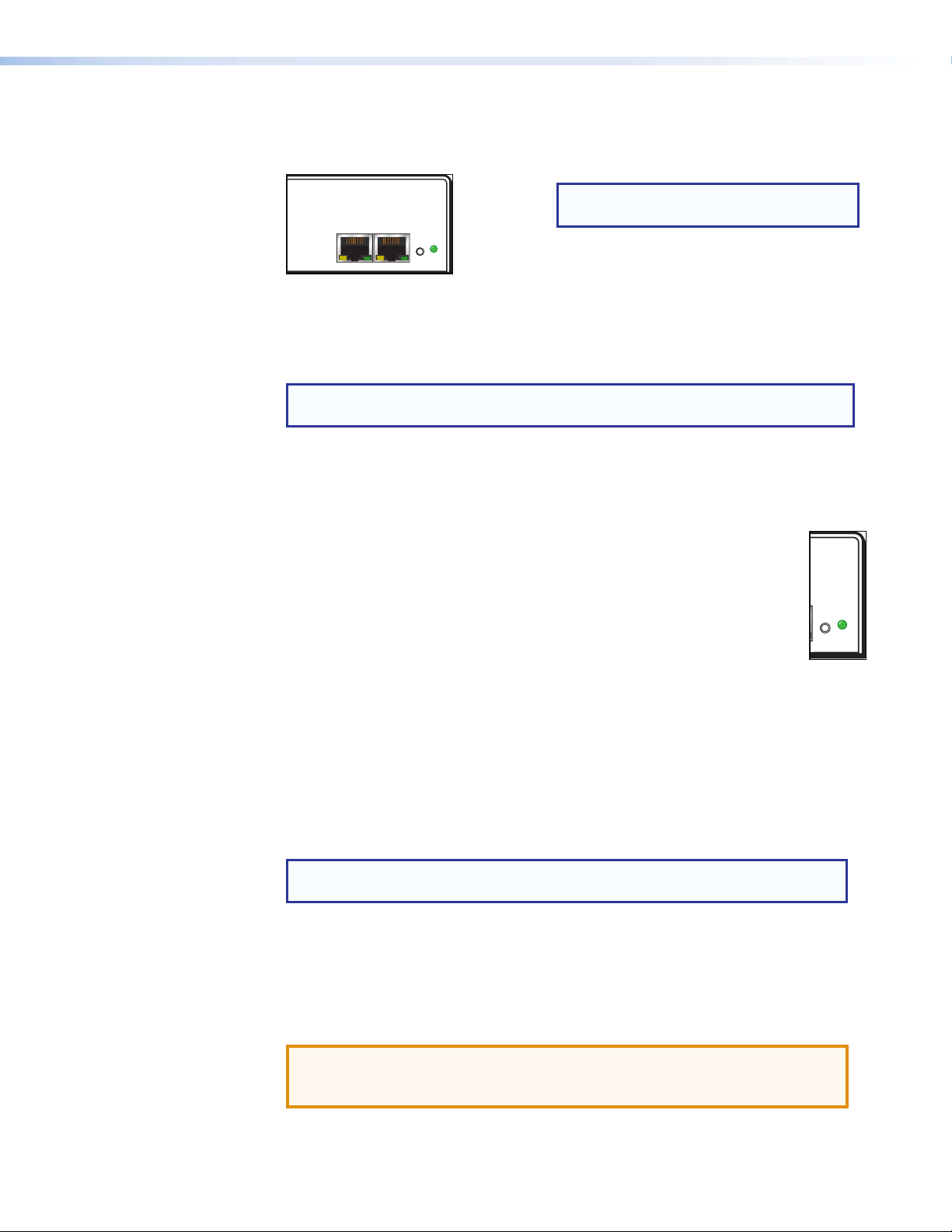
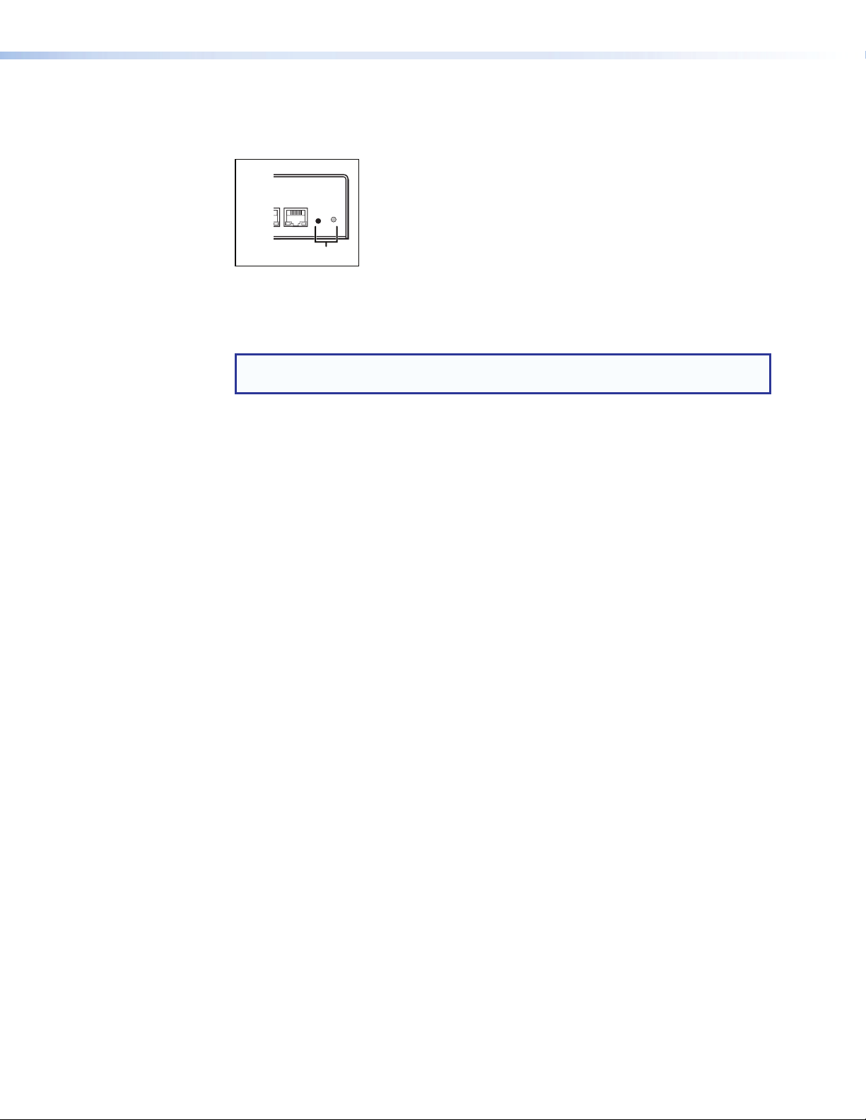
h EXP port connector — One RJ-45 jack for one additional DMP128 connection.
The EXP connector has a green LED to indicate proper connection to an active
expansion network and a yellow LED that blinks to indicate data activity.
NOTE: A one foot shielded CAT6 cable
LANEXP
RESET
is provided for the EXP connection.
Figure 6. EXP and LAN Connections
i LAN connector — A standard RJ-45 jack (see above) accepts a standard Ethernet
cable for network connection. The control system and DMP128 must be connected
to the same network.
NOTE: To connect the DMP128 directly to a computer Ethernet port, use a
crossover Ethernet cable.
• A yellow (ACT) LED indicates data activity on the connection.
• A green (Link) LED indicates the jack is connected properly to the network.
See SIS Programming and Control on page129 for additional information on
Ethernet cabling.
j Reset button and LED indicator — The reset button returns the DMP128
to different tiers of default states and can place the unit into an event
recording mode for troubleshooting. When using the reset function, the LED
flashes to signify the different tiers (see DMP128 Hardware Reset Modes
on page169). When not in reset mode, the LED operates as a power
indicator, duplicating the front panel LED operation.
RESET
k AT connections (AT models only) — Four RJ-45 jacks for Ethernet
connection form a 4-port Gigabit switch that interfaces with the AT bus. The AT
port expansion bus uses the Dante protocol for digital media networking allowing
connection of multiple DMP128AT models to form a larger matrix.
The AT bus supports 56 channels of audio input (Rx) per DMP128AT. Output
channel support (Tx) includes the eight line outputs, eight virtual returns (post
processing), and eight expansion outputs for a total of 24 channels. Audio from an
AT port is placed on a network and the audio channels assigned to the network
are available to any Dante-compatible device on the network, such as another
DMP128AT.
NOTE: The Dante Controller software is required for configuration of the AT
expansion bus (see Dante Controller Software Installation on page113).
l Telephone connections (P models only) — These optional connections provide
telephony access.
The POTS interface provides two RJ-11 telephone jacks to connect to the incoming
phone line (LINE) and the telephone (PHONE).
The telephone interface follows all applicable US and International standards.
ATTENTION: For telephone and network cabling, to reduce the risk of fire,
use a minimum conductor size of 26 AWG, UL Listed or CSA Certified
Telecommunication Line Cord.
DMP128 • Installation and Operation 8
Page 15
USB Configuration Port (Front Panel)
A front panel configuration port uses an Extron USB A Male to USB Mini B Male
Configuration Cable, 26-654-06 for connection to a PC computer USB port.
The USB 2.0 port uses a mini type-B connector to connect to a host computer for
control. The DMP128 USB driver must be installed prior to using the port (see Installing
the USB Driver on page15).
NOTE: The DMP128 appears as a USB peripheral with bi-directional
communication. The USB connection is used for software operation (see
Windows-based Program Control on page13), and SIS control (see SIS
Programming and Control on page129).
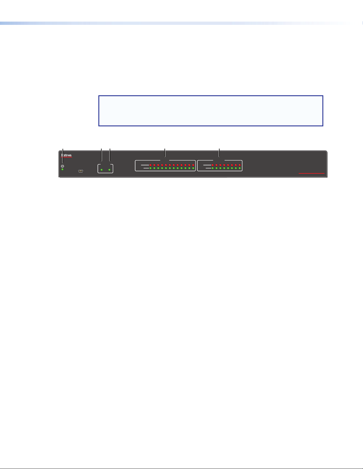
Front Panel Indicators
cda Ç É
INPUTSOUTPUTS
1
CONFIG
ACTIVITY
EXP LAN
Figure 7. DMP128 Front Panel
Power LED — The power indicator blinks during power-up and firmware uploads,
a
and lights solid when the DMP128 is operational.
2 3 4 5 6 7 8 9 10 11 12 2 3 4 5 6 7 8
CLIP
SIGNAL
CLIP
SIGNAL
1
DMP 128
DIGITAL MATRIX PROCESSOR
Activity Indicators — Two green LEDs labeled EXP (Ç) for the expansion audio port
b
and LAN (É) for the standard Ethernet port
(non-AT models)
Ç
Off — The unit is not connected to a second DMP128.
On — The unit is connected to another DMP128 and configured as the primary
unit.
Blinking — The unit is connected to another DMP128 and is currently
configured as the secondary unit.
(AT Models)
Ç
Off — Dante device is not responding.
On — The EXP port is connected to a non-AT DMP128 and configured as the
primary unit.
Blinking — The EXP port is not connected.
É Indicates activity on the corresponding rear panel Ethernet port connection.
Input Indicators — Stacked red (signal clipping) and green (signal present) LEDs for
c
inputs 1 through 12 . Each stack represents one input channel.
The green signal LED varies in brightness corresponding to the real-time input or
output signal level (see item d, below). It begins to light at – 60dBFS increasing
in steps to full intensity as the signal level increases. When the signal level reaches
– 3dBFS or above, the red clipping LED lights and remains lit as long as the signal
remains above – 3dBFS. When it falls below that level, the red LED remains lit for 200
milliseconds, after which the display resumes real-time monitoring of the signal level.
Output Indicators — Stacked red (signal clipping) and green (signal present) LEDs
d
for outputs 1 through 8. Each LED stack represents one output channel.
DMP128 • Installation and Operation 9
Page 16
Reset Actuator and LED
j
Hardware Reset Modes:
A recessed button on the rear panel initiates several reset modes. The rear panel LED
blinks to indicate the reset mode.
Rear Panel
34
RESET
LAN
EXP
Figure 8. Reset Button and LED
NOTE: The reset modes listed below close all open IP and Telnet connections, and
close all sockets.
With power on, when the reset button is held down, the LED blinks every three seconds.
At the first blink Mode 3 is available, at the second blink Mode 4 is available, and the third
blink indicates Mode 5 is available. The reset modes have separate and distinct functions
outlined below (see DMP128 Hardware Reset Modes on page169).
Mode 1 — Firmware reset: Disconnect power to the DMP128. Press and hold the
reset button while applying power to return the firmware to the version shipped with the
unit from the factory. Event scripting does not start when powered on in this mode. This
allows recovering a unit with incorrect or corrupt firmware.
All user files and settings are maintained. When returning the unit to an earlier firmware
release, some user web pages can work incorrectly.
Mode 3 — Events reset: With power on, press and hold the reset button until the reset
LED blinks once (~3 seconds). Release the reset button, then within one(1) second press
it again to toggle events on or off, depending on the current state.
• If event logging is currently stopped, following the momentary (<1 sec.) press, the
reset LED flashes twice indicating events logging has begun.
• If any events are currently running, following the momentary (<1sec.) press, the reset
LED flashes three times indicating the events logging has stopped.
If the second momentary press does not occur within 1 second, Mode 3 is exited.
Mode 4 — IP Address reset: With power on, press and hold the reset button about
6seconds until the reset LED blinks twice. Release the reset button, then within one (1)
second, press it again to reset the IP settings.
Mode 4:
• Enables ARP program capability
• Sets IP back to factory default IP address (192.168.254.254)
• Sets subnet back to factory default (255.255.0.0)
• Sets gateway back to factory default (0.0.0.0)
• Sets digital I/O port mapping back to factory default
• Turns DHCP off
• Turns events off
If a second momentary press does not occur within 1 second, the reset is ignored.
DMP128 • Installation and Operation 10
Page 17

Mode 5 — Factory default reset: With power on, press and hold the reset button
until the reset LED blinks 3 times (~9 seconds). Release then momentarily (<1 second)
press the reset button to return the DMP128 to factory default conditions. If the second
momentary press does not occur within one (1) second, the reset is exited.
The default (reset) state of the device is:
• All mix-points are set to 0dB gain and muted
• Input 1 is routed to Output 1
• Input 2 is routed to Output 2
• Input 3 is routed to Output 3
• Input 4 is routed to Output 4
• Input 5 is routed to Output 5
• Input 6 is routed to Output 6
• Input 7 is routed to Output 7
• Input 8 is routed to Output 8
• All outputs active (unmuted, 100% volume).
• No inserted or active DSP processing.
• All audio inputs are set to 0dB gain and muted.
• All preset and group master memory is clear (empty).
Digital I/O Ports
The four 6-pole 3.5 mm captive screw connector Digital I/O ports provide twenty
configurable digital input or output ports designed to connect to various devices such
as motion detectors, alarms, lights, LEDs, buttons, photo (light) sensors, temperature
sensors, relays (requiring ≥30 mA), and others.
All ports are tied to a common ground (one common ground for each 6-pole connector),
but can be individually configured to operate in one of two modes: digital input or digital
output.
The ports are configured using DSPConfigurator. Each port can be configured to monitor
or drive TTL level digital signals (see DigitalI/OPorts on page88).
DMP128 • Installation and Operation 11
Page 18

DMP Software
This section describes the control software for the DMP128, including:
• Software Control
• Windows-based Program Control
• DSP Configurator Program Basics
• Audio level, Mix-point, Processing Blocks, and Signal Chains
• Mic/Line Input Signal Chain Controls
• Telephone Rx (DMP128CP and DMP128CPAT only)
• Line Output Channels
• Virtual Bus Returns
• Output Mix Matrix
• Virtual Send Bus Mix Matrix
• Expansion Outputs Mix Matrix
• Group Masters
• DigitalI/OPorts
• Emulate Mode and Live Mode
• Presets
• Protected Configuration
• DSP Configurator Windows Menus
• Optimizing Audio Levels
• Signal Path Building Blocks
Software Control
The DMP128 can be controlled using the DSPConfigurator software, using SIS
commands with hyper terminal or DataViewer (see SIS Programming and Control
on page129), and accessed using embedded WebPages (see HTML Operation on
page155).
The DMP128 has the following connection options:
• RS-232 — One single stack 3-pole, 3.5 mm captive screw connector is used for
• LAN — 10 Mbps, 100 Mbps, halfduplex, full duplex connections are supported. Two
• USB 2.0 — A Mini B-type USB connector located on the front panel provides
bi-directional RS-232 (± 5 V) serial control.
See Rear Panel Features and Cabling on page6, for additional details on
connecting the RS-232 port.
LEDs indicate connection and activity status. The device has the following default
Ethernet configurations:
IP Address: 192.168.254.254 Default Gateway: 0.0.0.0
Subnet Mask: 255.255.0.0 DHCP: OFF
See Rear Panel Features and Cabling on page6, and Connection Options
on page129 for additional details on connecting the LAN.
high-speed USB 2.0 connectivity to a host computer, backward compatible to 1.0.
DMP128 • Software Control 12
Page 19
Windows-based Program Control
The DSP Configurator Control Program is compatible with Windows XP, WindowsVista,
and Windows7, and provides remote control of the input gain/attenuation, output volume
output adjustment, and other features.
DSP Configurator can control the DMP128 by any of the three control ports, RS-232,
USB, or LAN.
Updates to this program can be downloaded from the Extron website at
www.extron.com.
Installing the DSP Configurator Program
The program is contained on the Extron Software Products disk.
Install the software as follows:
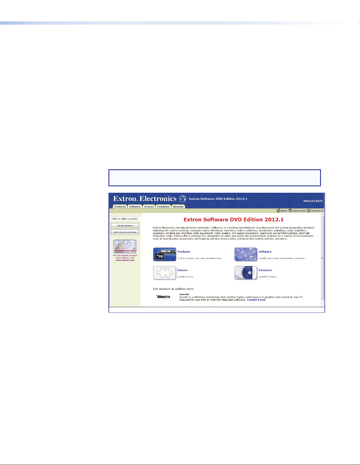
1. Insert the disk into the drive.
2. Click the Software tab or software icon. The software page opens.
NOTE: If the DVD setup program does not start automatically, run Launch.exe
from the DVD ROM directory using Windows My Computer.
Figure 9. DVD Software Menu
DMP128 • Software Control 13
Page 20
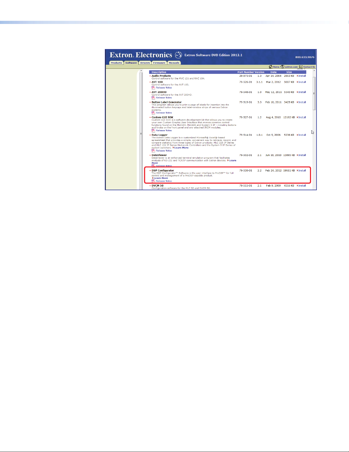
3. Scroll to the DSP Configurator program and click Install to its right.
Figure 10. DVD Control Software Menu
4. Follow the on-screen instructions. By default, the installation creates a
C:\Program Files\Extron\DSP_Configurator folder for the DSPConfigurator
program.
5. When the DSP Configurator installation is complete, the USB Installer starts
automatically (see figure 11, next page). Extron recommends installing the USB
drivers whether they are used immediately or not.
DMP128 • Software Control 14
Page 21
Installing the USB Driver
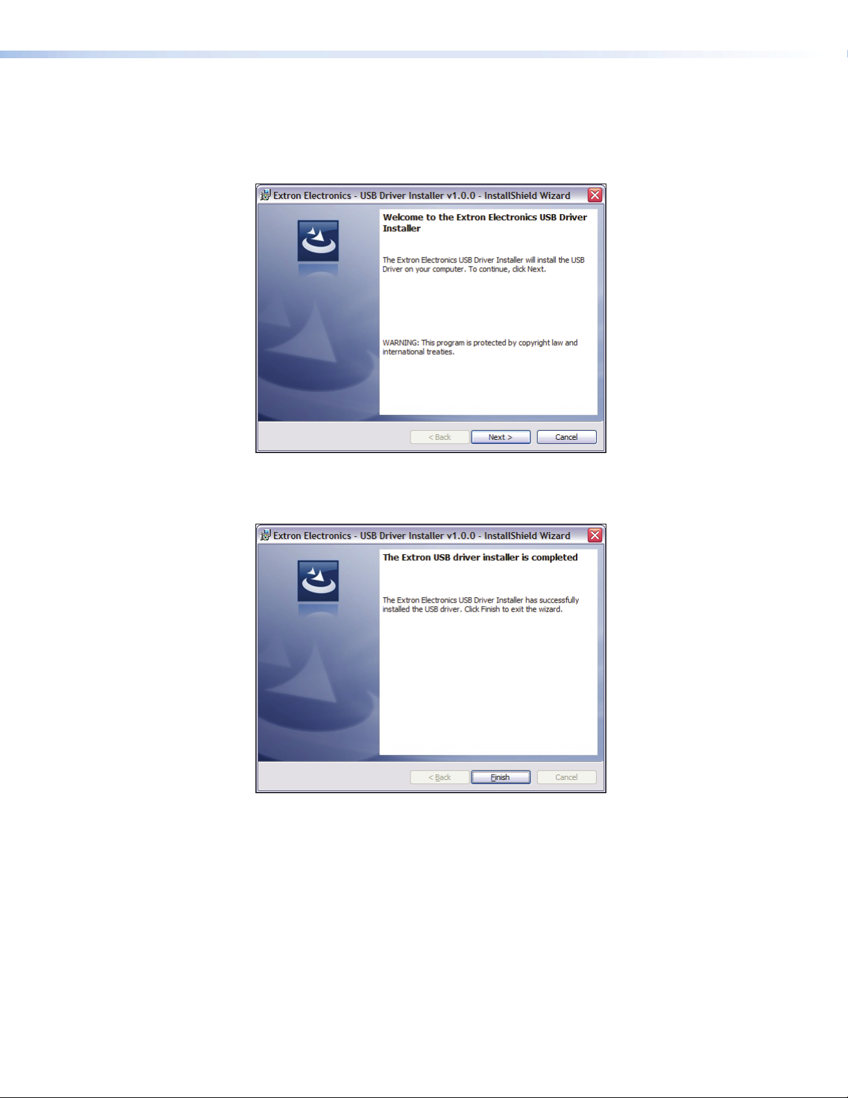
When the USB installer begins:
1. When the driver installation dialog opens, click Next to proceed (a status window
tracks the installation).
Figure 11. USB Installer Splash Screen
2. The USB driver installer launches. When the installer completes the installation of the
USB drivers, the following dialog opens:
Figure 12. Successful USB Driver Installation
3. Click Finish.
USB driver installation is complete.
DMP128 • Software Control 15
Page 22

DSP Configurator Program Basics
Starting the Program
NOTE: Extron recommends connection via the Ethernet LAN port for running the
DSPConfigurator program.
To run the DSP Configurator Program, click
Start > Programs > Extron Electronics > DSP Configurator > DSP
Configurator.
DSP Configurator starts in Emulate mode (see figure 13, next page). Also see Emulate
Mode and Live Mode on page89.
Using the Program
In the DSP Configurator Emulate mode, audio parameters can be selected, then
transferred to the DMP128 by switching to Live mode (while connected to a DMP128)
and pushing the configuration. Audio settings can also be tailored while connected to the
DMP128 for real-time auditioning of the audio output as adjustments are made
(see Emulate Mode and Live Mode on page89).
The main screen contains controls for the input and output channels, virtual sends and
returns, expansion outputs and inputs, and other information used in the operation of the
DMP128. There is too much information contained on the main screen to enable viewing
of the entire mix board at one time, so several methods, outlined on the following pages,
are provided to scroll through the screen.
DMP128 • Software Control 16
Page 23
a
b
e
d
c
Figure 13. DMP128 Navigation Aids
a Minimize buttons — Click to toggle the view of a selected section from minimum to
maximum. For example, the Inputs section is maximized with all processor blocks and
the mix-points shown. Clicking the button in this example shrinks the view to its minimum
screen area allowing items below to fill the screen.
b Maximize buttons — Click to toggle the view of a selected section from maximum to
minimum. For example, the Virtual Returns section is minimized with all processor blocks
and the mix-points hidden. Clicking the button in this example expands the view to its
maximum screen area.
c Toolbar — All tools and functions not directly available on the main screen are found here.
d Scroll Bar — When the sections are maximized such that the screen area takes up more
space than can be displayed at one time, items are pushed down or up and no longer
appear. Use the scroll bar to bring those items back into view.
e Channel Numbers — <Right-click> the channel number to hide a channel that has no
device connected or is not used in the current configuration.
NOTE: Hidden channels can be shown again using the tools menu and selecting
View > Show All Channels, then unchecking the hidden channels.
DMP128 • Software Control 17
Page 24
a
bcdfge
l
m
hi
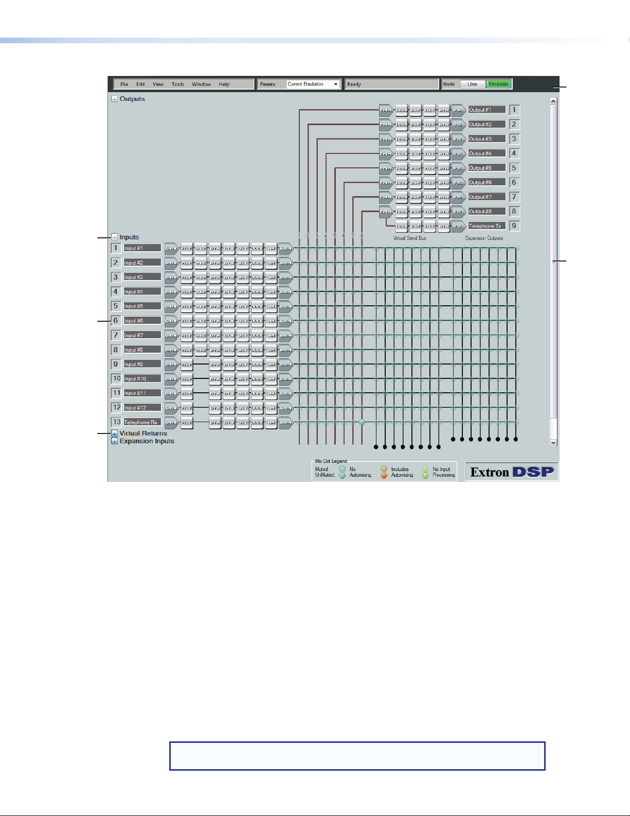
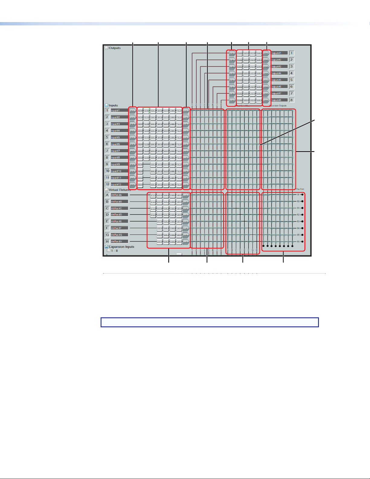
Figure 14. DMP128 DSP Configurator Main Screen
The DSP Configurator program screen consists of an input and virtual return signal
processor chain, the mix-points, and an output signal processing chain.
The main mixer is separated into segments as shown in figure 14.
NOTE: The expansion bus input mix-points are not shown in this view.
jk
a Input gain controls h Virtual returns signal processor channels
and pre-mixer gains
b Input signal processor channels i Virtual returns to output mix-points
c Input pre-mixer gains j Virtual returns to virtual sends mix-points
d Inputs to Outputs mix-points k Virtual returns to EXP sends mix-points
e Output trim control (post-mixer trim) l Virtual send bus to virtual returns mix-points
f Output signal processor channels m Inputs to expansion sends mix-points
g Output volume controls
DMP128 • Software Control 18
Page 25
Cut, Copy, or Paste Functions
The user can cut, copy, or paste a processor. These actions can be performed from a
context menu accessed by a right-click on the processor block, using the Edit menu, or
using the standard Windows keystrokes: <Ctrl+X> = cut; <Ctrl+C> = copy; <Ctrl+V> =
paste.
Multiple elements may be acted upon but the blocks copied must be compatible with
the desired paste blocks. A highlighted group of elements can be cut or copied to a
clipboard. The clipboard contents can then be pasted, but succeeds if there is an exact
one-to-one relationship between the clipboard contents and the block or blocks they are
pasted into.
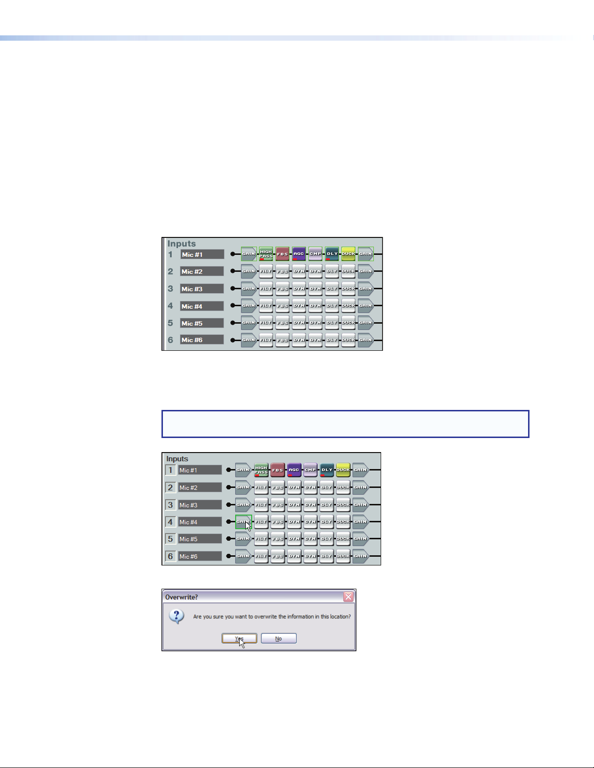
In the following example, the Mic #1 input signal path is copied to Mic #5. First click the
mouse and drag it across the entire signal path. The selected blocks are highlighted in
green. Press <Ctrl+C>, or use the Edit > Copy menu selection to copy the blocks.
As shown below, the starting point for the paste, (the upper/leftmost element), must first
be focused by clicking the mouse on it. Note the green focus outline that appears on the
Mic #4 Gain block. The clipboard elements are pasted using the context menu Paste
command, the Edit>Paste command from the toolbar, or <Ctrl+V>.
NOTE: A cut and copy of elements can be pasted to multiple locations. To copy the
clipboard to an additional location, click on the leftmost block and paste again.
The program warns that all settings in the section pasted to will be overwritten:
DMP128 • Software Control 19
Page 26
Click Yes. The entire Mic #4 input path is now identical to the Mic #1 input path including
signal levels, parameters settings, and mute/bypass selections.
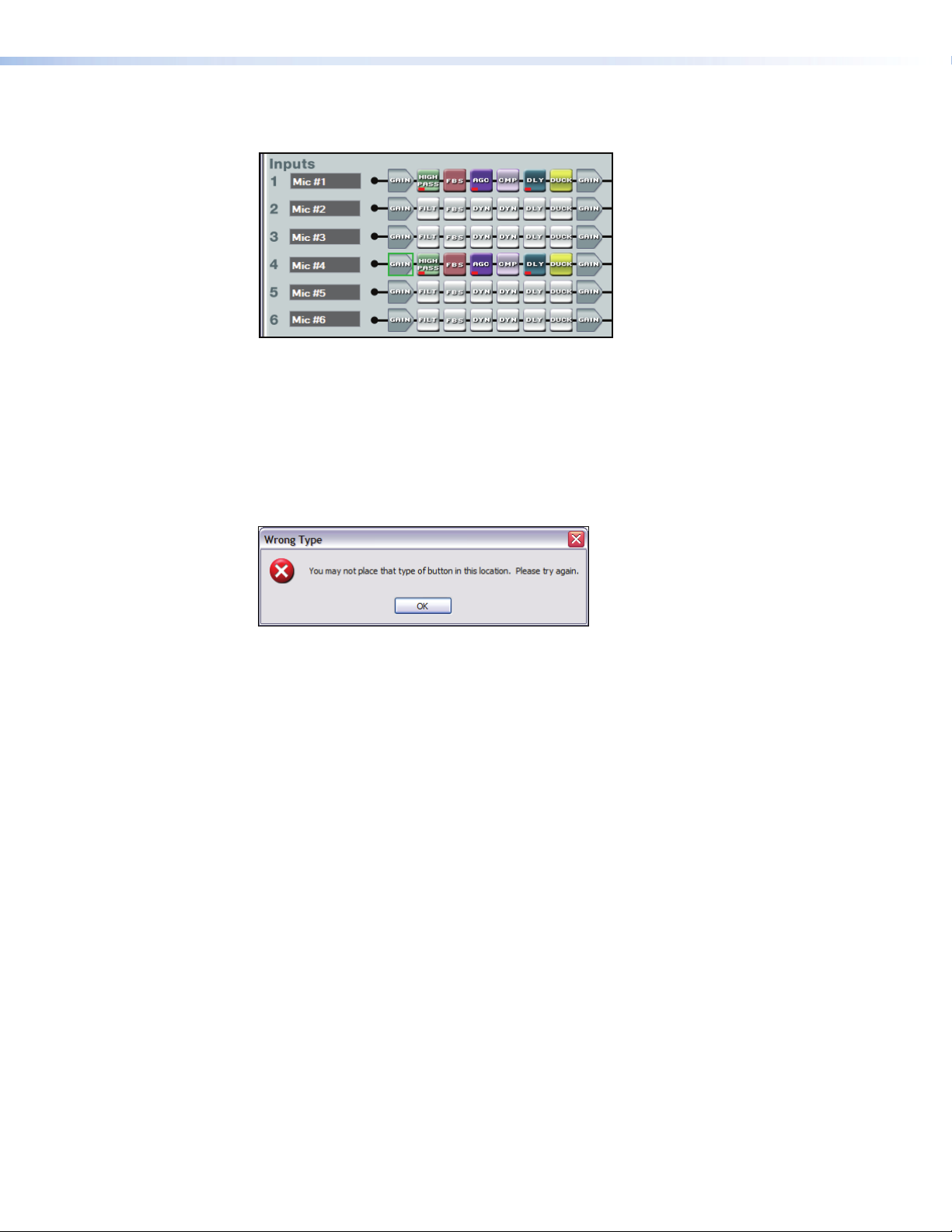
Any single processor block is copied, then pasted to a similar processor block in the
same or different input, virtual or output signal path. Mix-point gains can be copied from
one to another. Input gain, pre-mixer gain, post-mixer trim, and output volume can only
be copied to like gain blocks. For example, an input gain can be copied to any other
input gain, but cannot be copied to a pre-mixer gain, post-mixer trim, or output volume.
Mix-point settings can be freely copied between mix-points. The user is always asked
whether they want to overwrite the existing information. If an attempt is made to copy a
processor block setting to an incompatible block, the user is warned the action cannot be
completed.
Navigation
There are two methods of navigation around the screen:
• Keyboard • Mouse
When a new DSP Configurator file is opened, the upper left element (Output #1 Trim) is
the focus by default.
Keyboard Navigation
All screen elements including mix-points have the ability to receive focus using the tab and
arrow keys or using the arrow keys following a single click (see Keyboard Navigation on
page97).
Mouse Navigation
Left-click — Click on a processor block to bring focus to the block, as well as other
elements such as tabs, sliders, check boxes associated with the block. Other left-click
actions follow the Windows standard. In this user guide “click” always refers to a left-click
of the mouse button.
Right-click — A single right-click on a block brings up a context menu specific to that
processor block. Other right-click actions follow the Windows standard.
Double-click — Double-click on a box to open it from either the focused or unfocused
state of an element.
DMP128 • Software Control 20
Page 27
DSP Configurator Toolbar Menus
The DSP Configurator contains the following menu bar, arranged horizontally below the
title bar:
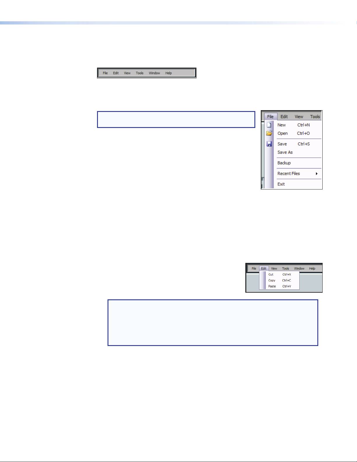
• File • Edit • View • Tools • Window • Help
File
NOTE: New, Open, and Recent Files are unavailable in
Live mode.
• New — Discards the current DSP configuration (after
prompting to save changes) and opens a blank
configuration file.
• Open — Loads and activates a previously saved DSP
configuration file.
• Save — Saves all changes to the current DSP configuration
file under the current file name. If the file has not previously
been saved, prompts for a file name.
• Save As — Saves all changes to the current DSP configuration file under a new file
name.
• Backup — Recalls and transfers all partial presets plus the current configuration to a
DSP configuration file within the DSP Configurator program.
• Recent Files — Opens a list of recently opened or saved DSP configuration files.
• Exit — Closes the DSP Configurator Program.
Edit
• Cut — Remove all parameters of a selected
processor block or set of selected blocks to the
clipboard. If not followed by a Paste command to a
different block, the parameters are restored.
NOTE: Processor blocks are not removed from the processor stream after a
Cut and a subsequent Paste operation. Only the parameters are moved.
Processor blocks and their parameters can be pasted only into another
block of the same type. For example, the input 1 filter block and all of its
parameters can be copied to the input 2 filter block but not to the input 1
delay block.
• Copy — Copies all parameters of a selected processor block, gain block, or set of
selected blocks to the clipboard.
• Paste — Inserts processor blocks and their parameters from the clipboard into the
the location selected.
DMP128 • Software Control 21
Page 28
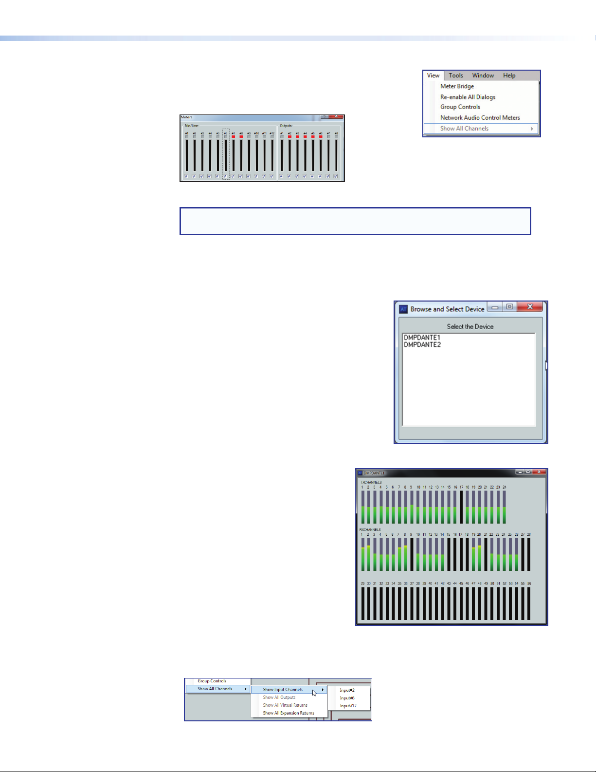
View
• Meter Bridge — Opens a Meters dialog box with
real-time meters that monitor signal levels at each input
and output.
Figure 15. Meter Bridge
NOTE: Meter Bridge is available in Live mode only while connected using the
LAN port.
• Re-enable All Dialogs — Re-enables all dialog boxes, the pop-ups that allow
changes to block parameters.
• Group Controls — Opens the Group Controls dialog box (see Group Masters on
page82).
• Network Audio Control Meters
(AT models only) — This menu allows the
user to see the AT meters for an attached Dante
device.
To view the meters:
1. From the main DSP Configurator screen
toolbar, select View>AT Meters.
2. The Browse and Select Device dialog box
opens (see right).
3. Double-click the applicable device. The
meter display opens showing the Tx and Rx
channels. See Viewing AT Channels with
AT Meters on page125 for addtional information.
• Show All Channels — Enables channels previously hidden from the main menu
to be viewed. The selection provides an option to either show all hidden channels for
that selection, or by moving to the right, an individual channel can be selected while
leaving the others hidden.
DMP128 • Software Control 22
Page 29
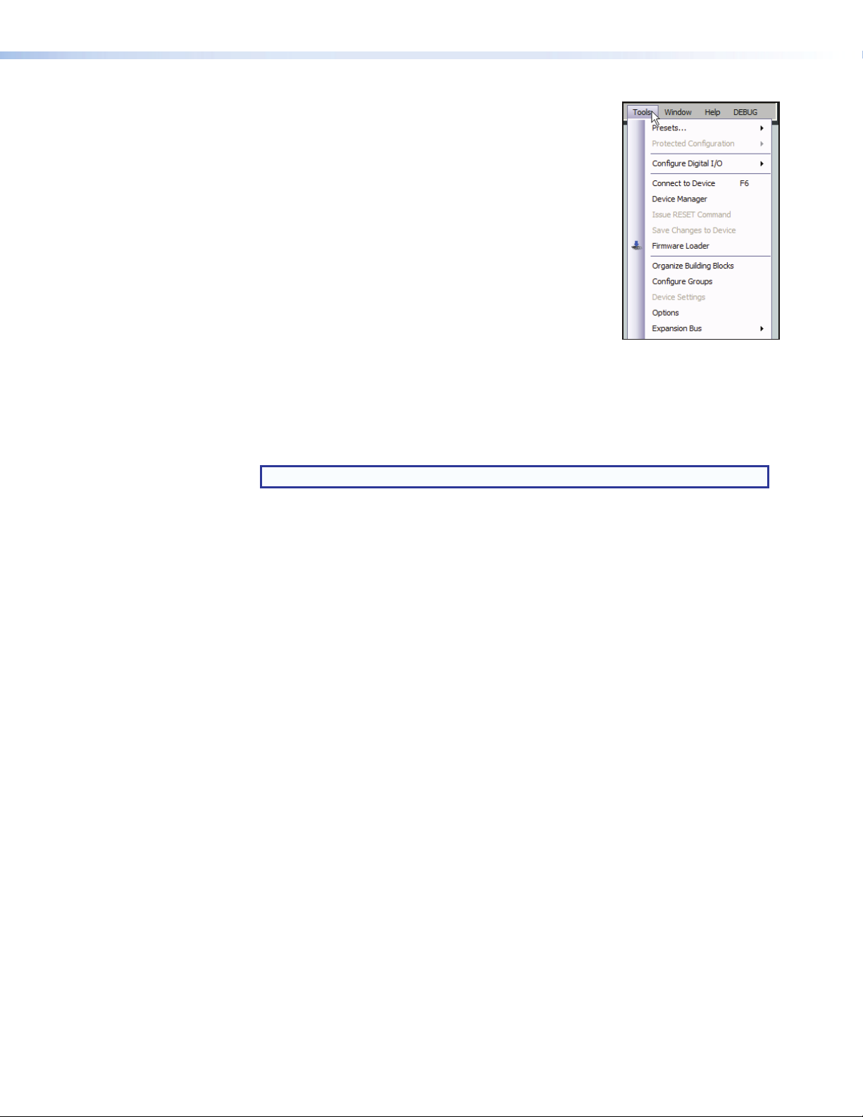
Tools
The Tools menu contains the following items and sub-menu:
• Presets — Provides three options:
• Mark All Items — Mark (select) all parts of the
current configuration (excluding presets), including
processors and mix-points to save as a partial preset.
• Save Preset — Save the currently marked
processors, and mix-points as a partial preset.
• Clear Marked Items — Unmark (deselect) all
parts of the current configuration (excluding presets),
including processors and mix-points.
• Protected Configuration (live mode only)—
Allows a user (typically the installer) to save and recall a
protected configuration. The protected configuration is useful to place the parameters
and values (with the exception of the device IP address) in a known state, either as
a troubleshooting tool or as a baseline configuration. The protected configuration,
once saved in the device, is always present and cannot be overwritten without
entering a user-defined Personal Identification Number (PIN) password. The protected
configuration is restored without a PIN.
NOTE: The default PIN is 0000.
• Save — Save the current configuration (excluding presets), including processors
and mixes as a password protected configuration. The DSPConfigurator
program prompts for a PIN to save.
• Recall — Recall the protected configuration.
• Change PIN — Change the PIN associated with the protected configuration.
• Configure Digital I/O — Opens a utility to configure digital I/O ports. The
DMP128 provides twenty digital I/O ports used to trigger external events from internal
actions, or for external events to trigger DMP actions (see DigitalI/OPorts on
page88).
• Connect to / Disconnect from Device (depending on Emulate or Live
mode) — Performs the same functions as the Mode Emulate and Mode Live
buttons.
• Device Manager — Opens the Device Manager dialog box. If a device is
connected, displays the details (model, MAC address, IP address). In addition, a
device can be added or removed, or a selected device cloned, and new folders can
be added to an existing device (see Device Manager on page81).
• Issue RESET Command — Initializes and clears the following: mix-points, presets,
processor blocks, and gain blocks. This reset is identical to the E ZXXX} SIS
command (see SIS Programming and Control on page129).
• Save Changes to Device (live mode only) — Saves configuration changes in the
DMP128 to non-volatile memory. This is advised if you are about to power off the
device.
• Firmware Loader — Launches the Firmware Loader program for firmware updates
(see Firmware Loader on page168).
• Organize Building Blocks — Provides organization of listed building blocks.
You can also import the building blocks file to use your set of building blocks on other
computers or export a building blocks file from another computer to use on yours (see
Signal Path Building Blocks on page105).
DMP128 • Software Control 23
Page 30
• Configure Groups — Opens the configure groups dialog box (see Group
Masters on page82).
• Device Settings (live mode only) — Opens a dialog box to change the
IPaddress, set administrator and user passwords, change the device name, change
the date and time, and to select the serial port baud rate.
• Network Audio Control — Launches Dante Controller to facilitate the discovery
of networked audio devices that are compliant with the network audio standard used
by the DMP128. Discovery is invoked upon launch, and retrieves device name, audio
channels, IP address and the MAC address (see Dante Controller Configuration
on page118).
• Phone Dialer — The phone dialer utility opens a dialog box that provides telephone
service capability for answering and initiating calls to remote attendees participating
in a conferencing session (see Telephone Rx (DMP128CP and DMP128CPAT
only) on page58).
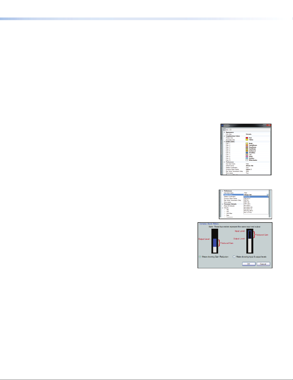
• Options — Opens a tabbed dialog box that allows
customization of the DSPConfigurator appearance and
operation.
• Colors — Tailor the appearance of the various graphs
and dialog boxes. Appearance uses a selected
color scheme for the complimentary and graph colors.
Complimentary Colors allows custom selection of
colors used with the various graphs and dialog boxes.
Graph colors change the row colors containing the
information and descriptions of the graphs seen in the
processor blocks.
• Preferences — The startup splash screen contains
options for selection of the devices to connect to, or to
Always ask on startup. That selection can be changed
using Default Device.
• If Show Meters is set to True, Dynamic Block
Meters can be used to tailor the appearance
of the dynamics meters in order to use the full
meter to show input and gain reduction, or to
show the level based on the output and gain
reduction.
DMP128 • Software Control 24
Page 31
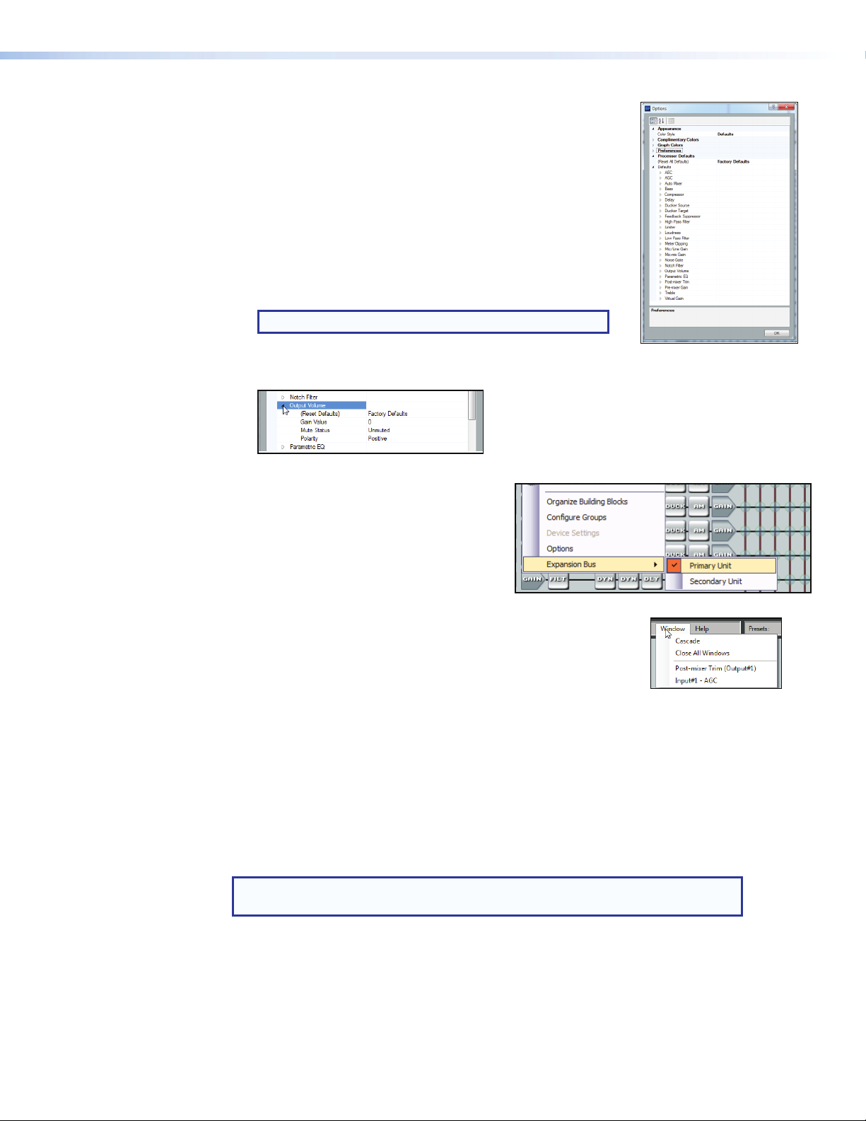
• Processor Defaults, Reset All Defaults —
>
Returns the DMP128 processor and level control blocks to
factory default settings. Each processor, and gain/volume/
trim block also has an individual default reset.
• Processor Defaults, Defaults — Individually selects
the default parameters for the various processor, trim, and
gain blocks.
Each row item contains default settings customized for the
processor, filter, trim, or gain block it represents.
Gain and volume blocks can be initially muted, while filter
and dynamics processor blocks can be initially bypassed.
NOTE: The bypass function is labeled Enable.
• To view the individual processor defaults, press [
gain, or meter device.
• Expansion Bus (live mode only) —
Provides a means to select control of either
the primary or secondary device (see Extron
EXP Bus on page79).
] to the left of the processor, trim,
Window Menu
• Cascade — Rearranges all open DSP Configurator program
screens, including dialog boxes, in a cascading array.
• Close All Windows — Closes all open dialog boxes.
• Individual Windows — Lists all open dialog boxes. Clicking on
the name brings the associated dialog box to the front of the desktop.
Help Selection
The Help menu contains the following elements:
• Contents — opens the Help file at the Contents tab.
• Search — opens the Help file at the Search tab.
• About... — displays the name of the application, the current version number, and
copyright information.
NOTE: Help can be activated via the F1 key from any main screen or dialog
(which accesses context sensitive Help).
DMP128 • Software Control 25
Page 32

Presets Drop-down
This drop-down list displays up to 32 presets. Select a preset to
display and either activate (Recall), abort the selection without
either recalling or deleting (Cancel), or delete it (Delete).
NOTE: An asterisk in the drop-down list indicates a preset exists only in the
DMP128 and has not been downloaded to DSP Configurator. After recall, the
asterisk is removed.
Mode Buttons
Provides selection between Live mode and Emulate mode (see
Emulate Mode and Live Mode on page89).
Backup
In Live mode (connected to a DMP128), when presets exist in the DMP128 that are
not present in DSPConfigurator (indicated by an asterisk next to the preset name), the
function halts and prompts the user to run a backup.
Backup (File > Backup) automates the recall of presets from the DMP128 to a DSP
configuration (.edc) file within DSP Configurator, then displays a prompt to save the file to
the hard drive. Backup is unavailable when the DSPConfigurator program is in Emulate
mode.
NOTE: A backup should not be performed during a live event.
DMP128 • Software Control 26
Page 33

a
bcdfge
l
m
hi
Figure 16. Control Blocks and Processor Chains
jk
Audio Level, Mix-point, Processing Blocks, and Signal Chains
As outlined in red above (see figure 16), all control blocks on the main DSP control screen
have one of three main functions in the overall signal chain:
• Level control (gain, trim, volume)
• Mix-point (signal routing)
• Signal processing (filter, AEC, feedback, dynamics, delay, duck, loudness, and
automix)
The signal chain varies depending on whether it is in the input, output, virtual bus, or
EXP bus stage. Each of the three types of signal processing channels; Input (a,b,c),
Output(e, f, g), and Virtual (h) shown in figure 16, consist of a series of two basic
types of control blocks specific to that chain: level control (gain a,c, trim e, and volume
controlg), and signal processors (frequency filters, feedback suppression, dynamics,
delay, ducking, AEC, AM, and loudness). Both types of control blocks are always present
in the chains. By default, gain controls are unmuted and processor blocks are bypassed
upon insertion. The default configuration can be modified in the options menu.
The EXP input- bus has only an AM processing block.
Gain, trim, mix-point, and volume blocks can be muted and processor blocks (after being
inserted) can be bypassed for signal comparison. Mutes and bypasses are shown by a
red indicator in the lower left of the block (see figure 17).
Figure 17. Input Gain Control Muted, Dynamics Processor (AGC) Bypassed
DMP128 • Software Control 27
Page 34

Level Control Blocks
Double-click the
desired processor.
To access a gain, trim or volume control to view a setting, make a change, or observe a
live audio meter (input gain and output volume blocks only), double-click the gain block
icon (see figure 18). This action opens a dialog box that contains the fader for that control.
Double-click a gain,
trim, or volume control.
A dialog box opens,
containing the full
fader control.
NOTE: In Emulate mode
(the startup mode),
the meter is not operational.
Figure 18. Accessing a Typical Gain Control Dialog Box
Level controls always have a control for setting the signal level and a digital indication of
its current setting. They can also have switches or indicators required for their specific
function.
Processor Blocks
Each processor block represents a menu of one or more processors that can be inserted
into the audio stream. For blocks that provide more than one processor, only one can
be selected. Each block can be inserted by a double-click or right-click>Insert
then select the desired processor (see figure 19). Once a block is inserted, the selected
processor displays in the block and the block changes color. Processor blocks default
to bypassed. Bypass is different from mute since the processor passes an unprocessed
signal when in bypass mode. To have them default to “not bypassed”, see Tools on
page86.
processor block.
Click the desired
-orRight-click the
processor block.
processor.
Click insert.
The selected processor is displayed in the
block.
To change processor variables, double-click the
block again to open the processor dialog box.
Click to select the
Figure 19. Selecting a Processor Block
DMP128 • Software Control 28
Page 35

Once a processor is inserted, to view associated parameters that define the selected
processor (such as a frequency curve) or to remove the bypass, double-click the
processor block. This action opens a new dialog box with parameters for the process (see
figure20).
Figure 20. Sample Processor Dialog Box
• Click Set Defaults to discard all custom settings and
reload the default parameters.
• Click Bypass to temporarily suspend processing without
removing the processor block. Red indicates the processor is bypassed.
By default, a processor block is bypassed when inserted (the Bypass button in the
processor dialog box is red).
NOTE: Figure 20 is an example of one type of dialog box. Contents and appearance
of each dialog box are unique to the processor type.
The block can be removed from the signal chain by clicking it to bring focus and pressing
<Delete> or by right-clicking and selecting Delete.
Detailed explanations of each signal chain with their processor blocks along with mix-point
operation follow in the next section.
DMP128 • Software Control 29
Page 36
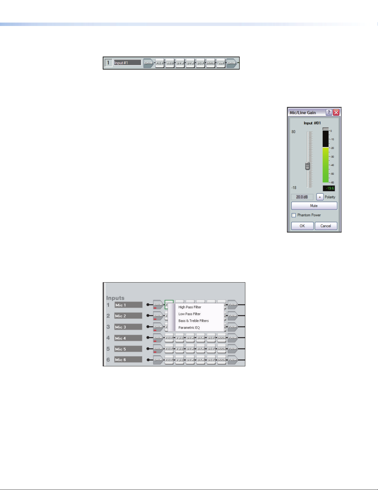
Mic/Line Input Signal Chain Controls
The input signal processor chain allows adjustments to program or microphone audio
material before input to the main mixer.
Gain Control (GAIN)
The gain control provides a single long-throw fader with a range of
– 18dB to +80dB, adjustable in 1dB increments with the fader or
in 0.1dB increments using direct entry in the level setting readout
below the fader. The peak reading meter holds the peak level for
one second, displaying it numerically in the box below the meter.
The default setting is unity gain (0.0dB).
The Phantom Power checkbox, turns the +48 VDC phantom
power on (checked) and off (unchecked). Phantom power is typically
used to power a condenser microphone.
The Mute button, silences the mic/line input.
The Polarity button, allows the polarity of wires connected to
the audio connectors (+/tip and – /ring) to be flipped to correct for
miswired connectors.
Filter (FILT)
Each filter block allows a total of five filters. The first filter is inserted from a processor list
that opens when the block is double-clicked or by selecting it from a context list when the
block is right-clicked (see figure 21).
Figure 21. Insert Filter Menu
Once inserted, double-click the processor block to change parameters of the filter. After
the first filter is inserted, up to four additional filters can be added to the filter block using
the dialog box. Select the desired filters from the following list using the drop-down boxes:
• High pass filter — A high pass filter passes a band of frequencies extending from a
specified cutoff frequency (greater than zero) up toward the high end of the frequency
spectrum. All frequencies above the specified cutoff frequency are allowed to pass,
while all frequencies below are attenuated.
The default cutoff is 100 Hz.
DMP128 • Software Control 30
Page 37
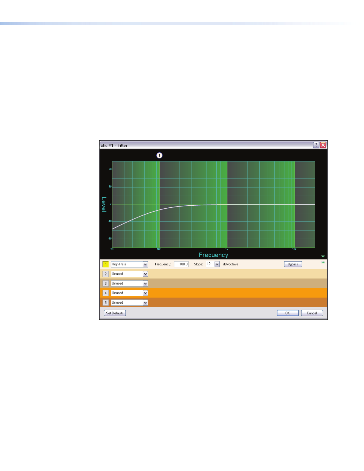
• Low pass filter — A low pass filter passes a band of frequencies extending from a
specified cutoff frequency (less than infinite) towards the lower end of the frequency
spectrum. All frequencies below the specified frequency are allowed to pass, while all
frequencies above are attenuated.
The default cutoff is 10 kHz.
• Bass and treble filters — Also known as shelving or tone controls, the separate
bass and treble filters cut or boost gain linearly above or below a specific frequency,
with the end-band shape giving the visual appearance of a shelf. The bass default
frequency is 100 Hz and the treble default is 8 kHz.
• Parametric equalizer filter — The parametric filter is a frequency equalizer that
offers control of all parameters, including amplitude (the amount of gain/boost or
gain reduction/cut applied), center frequency (frequency), and range of affected
frequencies (Q) around the center frequency.
Figure 22. Filter Block Dialog Box
Open the filter block dialog box to insert additional filters. Select a filter type from the
drop-down filter selection list. All filter parameters are modified using the Filter block dialog
box. Each filter loads with all applicable parameters displayed to the right of each filter
selection.
A balloon number appears at the top of the frequency graph display (see figure 22, a)
corresponding to the row number underneath the graph. The location of the balloon
number is at the frequency selection of that row.
DMP128 • Software Control 31
Page 38
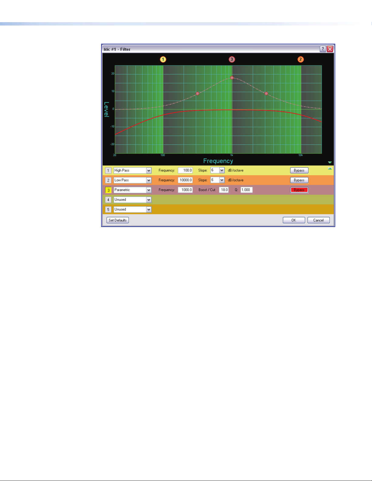
Figure 23. Filter Dialog Box, Filters Added
Within the dialog box, a filter is focused when a filter type is inserted, or is focused by
clicking the filter number to the left of the filter selection drop-down list. Note the box
number in row3 in figure 23 is highlighted in yellow, indicating it is the filter in focus. The
results of the filter in focus (independent of other filters) show in the graph as a dotted line
the same color as its filter row when bypassed. When active (not bypassed), the line is
solid.
When multiple filters are enabled, the graph indicates the focused filter result (independent
of other filters) in the color of the filter row in table. The composite response, the
combined effect of all filters not bypassed, is always displayed in red.
DMP128 • Software Control 32
Page 39

Figure 24. Filter Dialog Box, Filter Not Bypassed
Above the graph, each filter has a "handle" (circled in red above) placed directly above
the cutoff or center frequency whose number corresponds to the filter number (outlined in
red). Click a handle or click the table row to bring focus to that filter. Click+hold+drag the
handle horizontally to change the cutoff or center frequency.
The table below shows each filter type with default parameter settings. The table
immediately following shows the possible range for each parameter.
Type Frequency Parameter 1 Parameter 2
High Pass 100 Hz Slope: 6dB N/A
Low Pass 10000 Hz Slope: 6dB N/A
Bass 100 Hz Boost/Cut: 0.0dB Slope: 6dB
Treble 8000 Hz Boost/Cut: 0.0dB Slope: 6dB
Parametric 1000 Hz Boost/Cut: 0.0dB Q: 1.0
Filter Parameter Settings Range
Frequency 20 Hz to 20 kHz
Boost/Cut -24.0dB to +24.0dB
Q (Parametric EQ only) 0.707 to 15.000
Slope (HP & LP filters only) 1st Order (6dB) and 2nd Order (12dB)
DMP128 • Software Control 33
Page 40

High Pass
The high pass filter allows all frequencies above the specified cutoff frequency to pass
unattenuated. All frequencies below the cutoff are attenuated.
The default cutoff is 100 Hz.
Figure 25. High Pass Filter Response Curve
In figure 25, all frequencies lower than the specified frequency, 100 Hz, are attenuated
leaving the upper frequency response flat. Also note at the specified frequency (100 Hz),
the signal is about 3dB down, typical operation for high pass filters.
DMP128 • Software Control 34
Page 41

Low Pass
The low pass filter is the opposite of the high pass filter. All frequencies above the
specified frequency are attenuated allowing lower frequencies to pass.
The default cutoff is 10 kHz.
Figure 26. Low Pass Filter Response Curve
Here, the frequencies higher than the specified frequency, 10 kHz, are attenuated leaving
the lower frequency response flat.
DMP128 • Software Control 35
Page 42
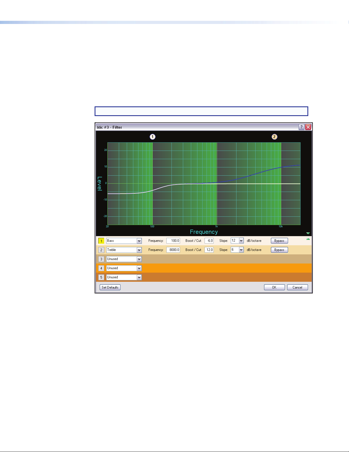
Bass and Treble Shelving
Bass and treble shelving can be added to the filter. Known as shelving or tone controls,
the separate bass and treble filters provide the ability to cut or boost gain linearly above
or below a selected frequency, with the end-band shape giving the visual appearance of a
shelf.
If only a bass or only a treble filter is required, either bypass the unneeded control or set it
to Unused in the selection box.
The bass default frequency is 100 Hz and the treble default is 8 kHz.
NOTE: Selecting Bass & Treble Filters inserts two separate filters.
Figure 27. Bass and Treble Shelving
The corner frequency of the controls can be selected to 0.1 Hz accuracy. Two slopes,
6 and 12dB/octave are available, along with the ability to boost or cut the signal up to
24dB.
DMP128 • Software Control 36
Page 43

Parametric (Equalizer)
The parametric filter is a frequency equalizer that offers control of all parameters, including
amplitude (the amount of gain [boost], or gain reduction [cut] applied), center frequency
(frequency), and range of affected frequencies (Q) around the center frequency. Q is the
center frequency divided by the bandwidth.
Up to five parametric filters can be placed in the filter block at one time, each set to a
different frequency creating a five band parametric equalizer. The control can boost or cut
the center frequency, and by changing the Q value, the range of affected frequencies can
be widened or narrowed around the center frequency. In general, a higher Q value results
in a narrower affected bandwidth.
To demonstrate how Q affects the filter, the following filter block (see figure 28) contains
five parametric filters centered at different frequencies, but with the same Q of 1.0. The
filter in focus (c) has a center frequency of 1000 Hz boosting that frequency +12dB over
a Q of 1.0. Note the markers on either side of the peak frequency are at about 300Hz on
the left and 3000 Hz on the right, a bandwidth of 2700 Hz.
Figure 28. Parametric Filter at 1000 Hz, Q: 1.000
DMP128 • Software Control 37
Page 44

By increasing the Q to 10.000, the center frequency remains the same. The markers show
the bandwidth of the filter narrowed to between 900Hz and 1200Hz, or about 300Hz
(see figure 29). Using the Q value, parametric filters can be used to notch out a very
narrow, or very wide range of frequencies.
Figure 29. Parametric Filter at 1000 Hz, Q: 10.000
The dialog box above shows the frequency curve for a single active filter. To add its effect
to the overall frequency response, remove the bypass on the other filters by clicking
Bypass.
DMP128 • Software Control 38
Page 45
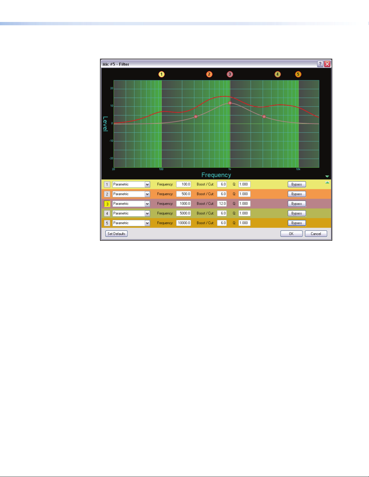
The overall frequency response is now shown as a solid red line with the filter in focus
located in row 3 (see figure 30 below) shown in the color of its table row.
Figure 30. All Parametric Filters Active
The parametric filter allows frequency selection accurate to 0.1 Hz and either 6 or 12dB
of slope.
DMP128 • Software Control 39
Page 46

Acoustic Echo Cancellation (AEC)
The DMP128 C models provide one acoustic echo canceller processor for each of the
first eight mic/line inputs. A single reference can be selected for each AEC from a list of
the twelve line inputs.
About AEC
Echo occurs when audio from a talker in the far end is received and amplified into the near
end listener’s room, with that sound then being picked up by microphones in the near end
acoustic space and sent back to the far end. The amount of signal sent back to the far
end talker can be substantial, and with the added transmission delay, the result is an echo
effect that seriously compromises communication in a teleconference or videoconference.
The Acoustic Echo Cancellation processor removes the potential echo signal at the near
end mic channel by comparing it to the received signal from the far end, designated as
the “reference,” and then creating an adaptive filter to cancel the potential echo before it is
sent back to the far end.
AEC Setup
Successful operation of the AEC processing block is a function of proper gain structure
and selection of the AEC reference (see Optimizing Audio Levels on page100). This
section provides an overview of the two elements.
Proper gain structure involves the relationship between the signal at the selected reference
and the signal at the mic input, within the context of proper levels for the reference and
mic inputs independently. The mic input gain setting is naturally optimized for the voice
level of the talker in that room; therefore the amount of signal from the far end that is
picked up by the mic is dependent on how much that far end signal is being amplified in
the near end room and the distance from the mic to the speakers.
The reference signal is the signal received from the far end, which is ultimately sent to a
sound reinforcement system within the near end room. The output of the video codec
might be connected to any of inputs 9 – 12.
In the AEC dialog, a reference can be chosen from any channel in one of three signal
chains:
• Input Channels
• Virtual Return Channels
• Output Channels
Extron recommends using an input channel as the reference. An output channel or a
virtual channel can also be used as a reference; however, doing so adds a little more delay
to the signal being referenced.
Using an output or virtual channel reference allows for the combining of input channels
to a single reference, for example, in a conferencing setup where both a telephone and a
video codec are used. In this case, both the telephone and video codec input channels
can be routed to an output or virtual return, with that output or virtual return then chosen
as the reference.
DMP128 • Software Control 40
Page 47
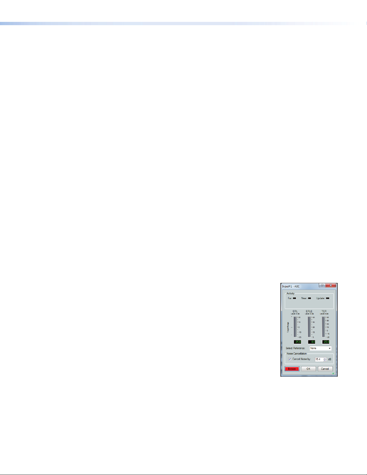
When using an output channel as a reference, the reference point is post volume control;
therefore, changes to the listening volume in the room affects the AEC gain structure (see
AEC Dialog, below). If you have an output channel on the DMP128 that is not being
used, you can isolate the reference channel from the channel being used for volume
control by routing reference signals to the unused output channel.
If you do want the reference signal to track with changes in listening volume, and want
more control over the actual reference level:
1. Route the far end signal to both the amplifier output and the virtual (unused) output.
2. Create a group master control that contains the amplifier output and virtual output.
Set soft limits for the group master control, as desired.
3. Set optimal level for the amplified output. Set optimal level for virtual output. Relative
levels between both settings will be maintained by using the group master control.
AEC Configuration
To insert and configure an AEC processor:
1. Insert an AEC processor on the desired input channel using one of the following
methods:
• Double-click the AEC (filter) block in the DSP Configurator workspace.
• Right-click the AEC block to open the context menu and select Insert AEC.
• Click the AEC block to select it (or use the arrow keys to navigate to the AEC
block) and press <Enter>.
2. Double-click the AEC processor to open it. Open the Select Reference
drop-down list and select a reference.
3. Click Bypass to disengage bypass. The AEC processor is now operational.
AEC Dialog
The AEC dialog contains a number of meters and indicator LEDs that are essential for
setting up gain structure and monitoring activity. The AEC reference must be selected
from a list, otherwise the echo canceller will not work. Noise
Cancellation, part of the AEC processor, is selected and adjusted
here. A detailed description of the AEC dialog components is
included below.
Activity LEDs
• Far – lights when activity is detected from the remote site.
• Near – lights when activity is detected from the local site.
• Update – lights when the AEC is updating, converging, or
reconverging.
DMP128 • Software Control 41
Page 48

Meters
• ERL – the ratio in dB between the signal at the reference and the signal at the AEC
channel input. When ERL is a positive number, the signal level at the AEC channel
input is lower than the signal at the selected reference (0 to +15dB is desirable).
• ERLE – the amount in dB of potential echo signal that the AEC algorithm, not
including NLP processing, is cancelling.
• TER – the sum of ERL + ERLE, in dB.
Select Reference
Select the AEC reference from a drop-down list, populated with
the following:
• Output channels (1 – 8)
• Input channels (1 – 12)
• Virtual Return channels (A – H)
Noise Cancellation
Noise cancellation can be switched on or off from the AEC dialog.
The noise canceller detects steady state noise, such as HVAC or
other continuous system noise, and effectively remove it without
causing audible artifacts.
Noise cancellation is engaged or disengaged using a checkbox.
When the box is checked, noise cancellation is engaged, or
switched on. When cleared, noise cancellation is disengaged, or
switched off. The default setting is noise cancellation switched on
and set to 15dB of noise attenuation.
Up to 20dB of noise cancellation is available, in 0.1dB
increments.
Setting Gain Structure for AEC
It is important to optimize the audio levels of the DMP128 for AEC to be effective (see
Optimizing Audio Levels on page100).
DMP128 • Software Control 42
Page 49
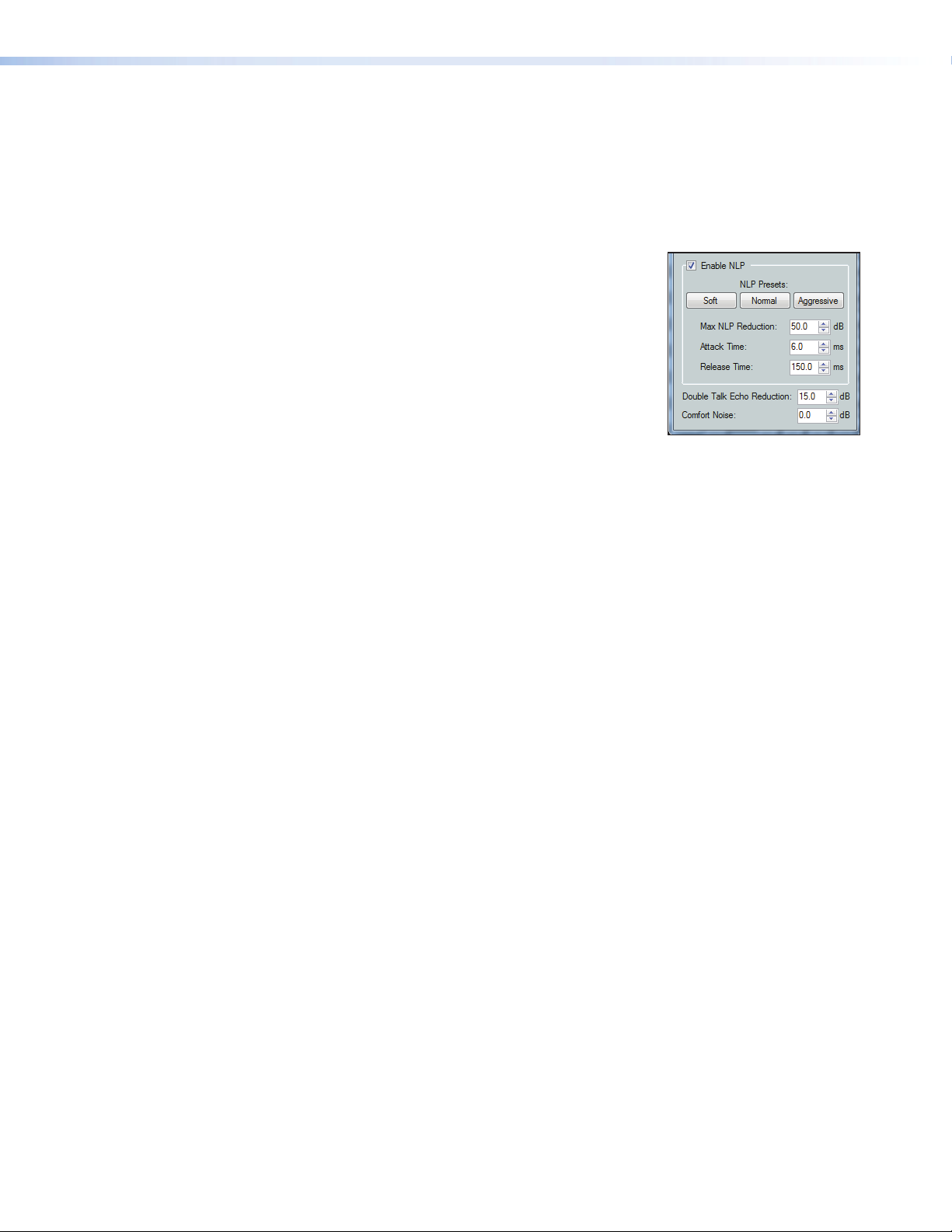
Advanced AEC Controls
Click on the open/collapse icon at the bottom of the AEC dialog to reveal the advanced
AEC controls.
Advanced control functionality is as follows:
Non-linear Processing (NLP) Controls
• Enable NLP — this box is selected by default. NLP is
necessary for the removal of echo.
• NLP Presets — click a button to load a set of values
to the three NLP parameters; Max NLP Reduction,
Attack Time, and Release Time.
• Soft
• Normal
• Aggressive
The default parameters (shown at right) match the Normal
preset.
• Max NLP Reduction – the maximum possible reduction in echo artifacts that can
be applied. The range is 0.0 to 80.0dB in 0.1 dB increments.
Default is 50.0dB.
• Attack Time – the speed in which NLP is applied. The range is 0.0 to 100.0msec
in 0.1 msec increments.
Default is 6.0msec.
• Release Time – the speed in which NLP is released. The range is 1.0 to
3000.0msec in 0.1 msec increments.
Default is 150.0msec.
Additional Controls
• Double Talk Echo Reduction – sets the amount of echo reduction applied
during double-talk. The range is 0.0 to 20.0dB in 0.1 dB increments.
Default is 15.0dB.
• Comfort Noise – sets a comfort noise level in dB to eliminate states of complete
silence, which could be perceived as a failed connection. The range is 0.0 to 40.0dB
in 0.1 dB increments.
Default is 0.0dB which turns comfort noise off.
DMP128 • Software Control 43
Page 50

Dynamics (DYN)
A dynamics processor alters the dynamic
range, the difference between the loudest
to the quietest portions, of an audio signal.
Each input channel provides two dynamics
processor blocks that, when inserted, provide
one of four types; AGC, Compressor, Limiter,
or a Noise Gate processor.
Once a processor has been inserted, individual
processor parameters can be changed in the
dialog box, accessed by double-clicking the
processor block. For comparison, the block
can be bypassed by clicking Bypass.
All parameters are displayed in a text box and have a resolution to 0.1 increments.
Parameters can be set by direct entry in the text box to replace existing text, then press
<Enter>, or <Tab>, or clicking to another area. Threshold, gain/attenuation, target,
and ratio parameters have adjustment points on the graph display. Use the mouse to
click+drag the graph point to the desired destination or value. All time values have a
horizontal slider allowing adjustment in 1 ms increments by either a click+drag of the
slider handle, or focusing on the slider, then using left or right arrow keys (the <Page Up>
and <Page Down> keys adjust in increments of 10 ms).
The table below lists each dynamics processor type, parameters, and factory default
settings for the processor.
Parameter AGC Compressor Limiter Gate
Threshold -40.0dB -30.0dB -10.0dB -65.0dB
Max Gain 12.0dB
Target -10.0dB
Window 12.0dB
Attack Time 500.0 ms 5.0 ms 2.0 ms 1.0 ms
Release Time 1500.0 ms 100.0 ms 50.0 ms 1000.0 ms
Ratio 2.0 :1 20.0 :1
Hold Time 0.0 ms 100.0 ms 50.0 ms 300.0 ms
Max. Attenuation 25.0dB
Soft Knee Off Off
Details of the individual dynamics blocks follow.
DMP128 • Software Control 44
Page 51
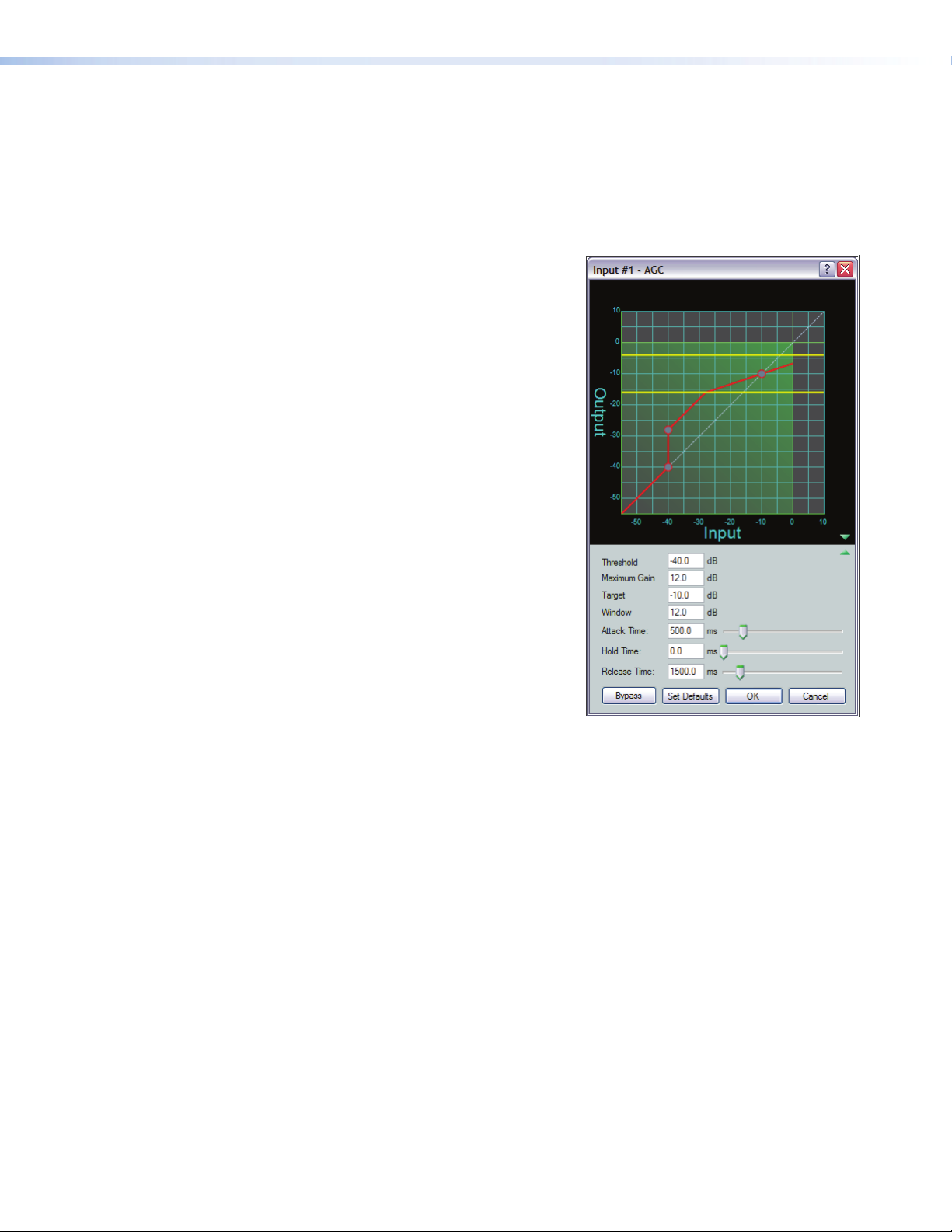
AGC (Automatic Gain Control)
AGC adjusts the gain level of a signal based on the input strength to achieve a more
consistent volume. Below the set threshold, the signal is not affected. Above the
threshold, weaker signals are boosted up to the maximum gain setting to reach a
user-defined target level. As the signal level approaches the target level it receives less
gain or no gain at all. Once the signal level reaches the target level all gain is removed.
Click in each field or use the sliders to change the values.
Threshold — The input level where maximum
gain is applied (after the attack time is
exceeded). On the graph at right follow the red
input level from the lower left to -40dB where
the first red circle is. Signal levels less than
-40dB remain at their original levels. Signal
levels at or exceeding -40dB have up to 12dB
of gain applied (Maximum Gain).
The threshold level can be adjusted from -80.0
to 0.0dB in 0.1dB increments.
Default is -40.0dB.
Maximum Gain — The highest amplification
applied to a signal exceeding the threshold
and up to the lower limit of the window (see
Window below).
Maximum Gain can be set from 0.0dB to
+60dB in 0.1dB increments.
Default is 12.0dB.
Target — The desired average signal level of
the output when AGC is applied. AGC can vary
the gain according to the input signal level,
specified target level and maximum gain. As the
signal approaches the target level of – 10dB,
gain is reduced until at – 10dB, gain is no
longer applied.
The target level can be adjusted from -40dB to 0.0dB in 0.1dB increments.
Default is – 10.0dB.
Window — Indicated by two yellow lines, is a specified range above and below the target
level. Below the lower line maximum gain is always applied to the signal. When the signal
reaches the window, gain control begins scaling in a linear fashion to achieve smoother
results as the signal reaches the target level.
The window range can be set in 0.1dB increments from 0.0dB to 20.0dB.
The default threshold is – 40dB. The default target level is – 10.0dB. The default window
range is 12.0dB.
Attack Time — Adjusts the time delay for AGC to engage after the input signal level
reaches or exceeds the threshold level.
Attack time can be adjusted from 0.0 to 3000.0 ms in 0.1ms increments.
Default is 500.0 ms.
Hold Time — Adjusts how long AGC continues to boost the signal after the input signal
drops below the threshold and before release time begins.
Hold time can be adjusted from 0.0 to 3000.0ms in 0.1 ms increments.
Default is 0.0 ms.
Release Time — Adjusts the time it takes to return the signal to normal (unprocessed)
levels after the signal no longer exceeds the threshold level setting. Release time begins
only after hold time is reached.
Release time can be adjusted from 10.0 to 10000.0 ms in 0.1ms increments.
Default is 1500.0 ms.
DMP128 • Software Control 45
Page 52

Compressor
The compressor regulates signal level by reducing, or compressing, the dynamic range
of the input signal above a specified threshold. The input level to output level ratio
determines the reduction in the dynamic range beyond the threshold setting. For example,
with a ratio setting of 2:1, for every 2dB of input above the threshold, the compressor
outputs 1dB.
Compression is commonly used to contain mic levels within an acceptable range for
maximum vocal clarity. A compressor can also make softer sounds louder in one of two
ways. The dynamic range can be reduced by compressing the signal above the threshold
while raising the post-compressor gain/trim (referred to as "make-up gain"). Alternately,
the input signal can be increased while the compression ratio above the threshold is
increased correspondingly to prevent clipping. Both techniques have the effect of making
louder portions of a signal softer while at the same time increasing softer signals to raise
them further above the noise floor.
Compression can also be used to protect a system or a signal chain from overload similar
to a limiter. Click in each field or use the sliders to change the values.
The default threshold is -30dB and default ratio is 2.0:1.
Threshold — The input signal level above
which compression begins (subject to attack
time) and below which compression stops
(subject to hold and release time).
The threshold level can be adjusted from
-80.0 to 0.0dB in 0.1dB increments.
Default is -30.0dB.
Ratio — The input signal level reduction
when compression is engaged.
Ratio can be adjusted from 1.0 to 100.0 in
0.1 increments.
Default is 2.0:1.
Attack Time — Adjusts the time delay for
compression to engage after the input signal
level reaches or exceeds the threshold level.
Attack time can be adjusted from 0.0 to
200.0 ms in 0.1ms increments.
Default is 5.0 ms.
Hold Time — Adjusts how long compression
continues after the input signal drops below
the threshold and before release time begins.
Hold time can be adjusted from 0.0 to
500.0ms in 0.1 ms increments.
Default is 100.0 ms.
Release Time — Adjusts the time it takes to return the signal to normal (unprocessed)
levels after the signal no longer exceeds the threshold level setting. Release time begins
only after hold time is reached.
Release time can be adjusted from 10 to 1000.0 ms in 0.1 ms increments.
Default is 100.0 ms.
Soft Knee — Select the Soft Knee checkbox to smooth and soften the transition from
uncompressed to compressed output levels. There are no adjustments.
DMP128 • Software Control 46
Page 53

Limiter
The limiter restricts the input signal level by compressing its dynamic range above a
specified threshold. The limiter is most commonly used to prevent clipping, protecting a
system against component or speaker damage. While the limiter is closely related to the
compressor, it applies a much higher compression ratio of ∞:1 above the threshold. The
ratio is fixed and cannot be changed. Click in each field or use the sliders to change the
values.
Threshold — The input signal level above
which limiting begins (subject to attack time)
and below which compression stops (subject
to hold and release time).
Threshold level can be adjusted from – 80.0
to 0.0dB in 0.1dB increments.
Default is – 10.0dB.
Attack Time — Adjusts the time delay for
limiting to engage after the input signal level
reaches or exceeds the threshold level.
Attack time can be adjusted from 0.0 to
200.0 ms in 0.1ms increments.
Default is 2.0 ms.
Hold Time — Adjusts how long limiting
continues after the input signal drops below
the threshold and before release time begins.
Hold time can be adjusted from 0.0 to
500.0ms in 0.1 ms increments.
Default is 50.0 ms.
Release Time — Adjusts the time it takes
to return the signal to normal (unprocessed)
levels after the signal no longer exceeds the
threshold level setting. Release time begins
only after hold time is reached.
Release time can be adjusted from 10 to 1000.0 ms in 0.1 ms increments.
Default is 50.0 ms.
Soft Knee — Select the Soft Knee checkbox to smooth and soften the transition from
uncompressed to compressed output levels. There are no adjustments.
DMP128 • Software Control 47
Page 54

Noise Gate
The noise gate allows an input signal to pass only when it exceeds a specified threshold
level. Above the threshold level, the signal passes unprocessed; below the threshold the
signal is attenuated at the rate set by the ratio adjustment. The typical setting of the noise
gate threshold is just above the noise level of the environment or source equipment. That
allows signals that are above the noise to pass, and attenuates the noise when there is no
signal to eliminate background noise. Click in each field or use the sliders to change the
values.
Threshold — is the input signal level below
which attenuation (gating) begins (subject to
attack time) and above which gating stops
(subject to hold and release time).
The threshold level can be adjusted from
-80.0 to 0.0dB in 0.1dB increments.
Default is -65.0dB.
Max Attenuation — is the maximum
attenuation of the signal when it drops below
the threshold.
Maximum attenuation can be adjusted from
0.0 to 80.0dB in 0.1dB increments.
Default is 25.0dB.
Ratio — is the input signal level reduction
when gating is engaged.
The ratio can be adjusted from 1.0 to 100.0
in 0.1 increments.
Default is 20.0:1.
Attack Time — adjusts the time delay for
gating to engage after the input signal level
drops below the threshold level.
Attack time can be adjusted from 0.0 to
200.0 ms in 0.1ms increments.
Default is 1.0 ms.
Hold Time — adjusts how long gating continues after the input signal drops below
the threshold. If the signal is still below the threshold when hold time ends, release time
begins.
Hold time can be adjusted from 0.0 to 500.0ms in 0.1 ms increments.
Default is 300.0 ms.
Release Time — adjusts the time it takes to return the signal to normal (unprocessed)
levels after the signal is no longer below the threshold level setting. Release time begins
only after hold time is reached.
Release time can be adjusted from 10 to 1000.0 ms in 0.1 ms increments.
Default is 1000.0 ms.
DMP128 • Software Control 48
Page 55

Delay (DLY)
The delay processor block, when inserted, provides a means to delay the audio signal.
Audio delay syncs audio to video or can time-align speakers that are placed at different
distances from the listener. The DMP128 can set delay by either of two criteria: time or
distance (feet or meters).
The default unit setting is time with a range of 0.0ms to 200.0 ms adjustable in 0.1 ms
steps. Default is 100.0 ms.
Settings are controlled with a vertical slider and indicated in the readout field. Click within
the readout field to change the value, or change the number, then press <Enter>, or press
<Tab>, or click away from the field.
Figure 31. Delay Dialog
Slider adjustments made in feet or meters correspond incrementally to the distance
required to make 1 ms, or 5 ms adjustments (detailed in the table below). If more precision
is required, enter time in 0.1 ms increments into the readout field.
Method Time Feet Meters
Click + drag 1 ms ~1.1 feet ~0.3 m
Focus + arrow 1 ms ~1.1 feet ~0.3 m
Focus + Page Up/Down 5 ms ~5.6 feet ~1.7 m
When distance (feet or meters) is chosen, the conditions (temperature) field becomes
available and can be set either by degrees Fahrenheit or Celsius by clicking the
appropriate selection button. When entering a distance, time delay compensation is
automatically modified based on differences in the speed of sound due to air temperature.
Default is 70 degrees Fahrenheit.
NOTE: When using distance (feet or meters), set a temperature value first, then set
the distance.
DMP128 • Software Control 49
Page 56

Ducking
Ducking provides a means to duck, or lower, the level of one or
more input signals when a specified source must take precedence.
The ducking processor block, when inserted, provides a means
to duck one or more mics and program material (ducking targets) when the processor
detects a signal from the ducking source. Ducking lasts for the duration of the interrupting
signal (ducking source) determined by the threshold setting (plus hold and release time)
and restores the original levels of the ducked inputs once the other signal has ceased.
NOTE: Ducking is not functional when an input chain includes active automixing. If
the input to output mix-point is orange, indicating it includes automixing, ducking
will not function for that input. To enable ducking either delete the automix
processor in the signal chain or uncheck Includes Automixing at the
mixpoint.
Ducking is useful when:
• Program material needs to be
attenuated in order to more clearly
hear a narrator voice.
• One microphone, such as one used
by a master of ceremonies, needs
to have priority over other mics,
program material, or both.
• A paging mic needs to attenuate all
other signals.
All ducking processor blocks are
controlled via a common dialog box
that opens when any of the ducking
blocks are selected. All empty ducking
processor blocks have no ducking
source or target settings by default.
When the first ducking source is
inserted (shown at right), no ducking
targets are selected.
Ducker Configuration
Input #1
Enable Source Mic/Line
Duck:
Input #2
Input #3
Input #4
Input #5
Input #6
Input #7
Input #8
Input #9
Input #10
Input #11
Input #12
Vtr Send A
Vtr Send B
Vtr Send C
Vtr Send D
Vtr Send E
Vtr Send F
Vtr Send G
Vtr Send H
Settings:
Threshold
Attack Time
Hold Time
Release
by (dB):
1000.0
1000.0
20.0
20.0
20.0
20.0
20.0
20.0
20.0
20.0
20.0
20.0
20.0
20.0
20.0
20.0
20.0
20.0
20.0
20.0
20.0
-30.0
Priority
Input #1
Input #2
Input #3
Input #4
Input #5
Input #6
Input #7
Input #8
Input #9
Input #10
Input #11
Input #12
dB
ms
1.0
ms
ms
NOTES:
• Signal reduction is not cumulative. Ducking reduces an input by the amount
set in the by (dB): text box next to the input selection even if it is being
ducked by another ducking source (see Ducking and Priority Ducking on
page53).
• Duck targets do not affect signals routed to expansion outputs 1 through 8.
• Duck targets do affect signals routed to expansion outputs 9 through 16.
DMP128 • Software Control 50
Page 57
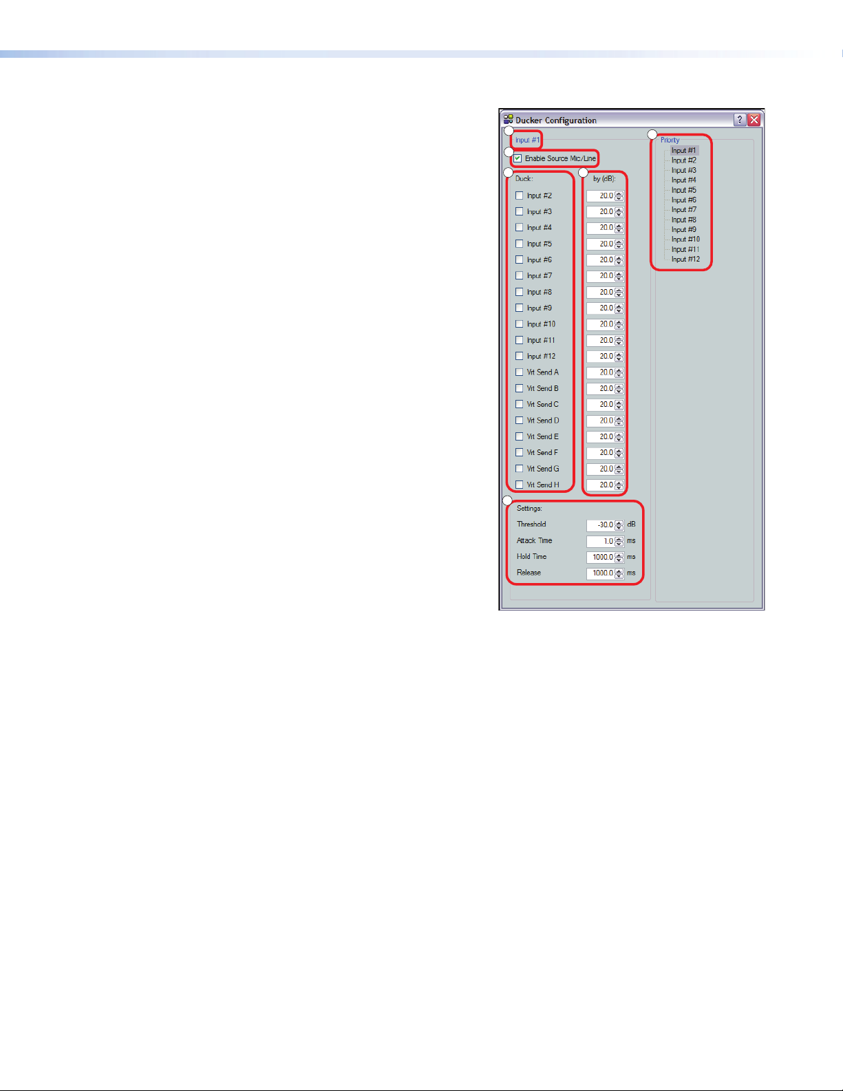
Ducking Configuration
Ducking is configured in a dialog box that opens when an
active ducking processor block is double-clicked.
a
Current Source
Shows the input selected as the ducking source. Ducker
settings affect the input channel shown here. When a
ducker dialog is opened, the current source defaults to
that channel. The current source can also be selected via
the priority readout/source selector (see below).
b
Enable Source Mic/Line checkbox
When checked, ducking is enabled for the current source
and the ducker processor block is lit. When cleared,
ducking is disabled for the current source and the ducker
processor block is unlit.
c
Duck: (targets)
Shows all potential input targets. Only inputs checked are
ducked. The current source is not available as a target (a
source cannot duck itself). If the current source has been
designated as a target of another input channel, that input
channel is not available (a target cannot be the source).
d
by (dB):
Individual attenuation settings for each duck target indB.
The default is 20.0dB. If additional attenuation of a target
is required, increase this value.
The attenuation range is 80.0 to 0.0dB in 0.1dB
increments.
a
b
c
f
e
d
e
Priority
Displays the hierarchy of ducking source to duck targets.
Priority levels are displayed in tree fashion. Input channels that are targets being ducked by a source are
shown as indented below the source. Any input channel displayed in the tree is an active link. Click an
input channel to select that channel as the current source. The current source indicator (a) reflects the
selected input channel.
f
Settings:
Used to configure the parameter settings for the ducker source. When a ducker block is copied, these
settings are transferred.
Threshold — Sets the input signal level, indB, the ducking source must exceed before ducking
begins. If ducking does not occur quickly enough to avoid loss of speech or program material from the
ducking source, decrease this setting. If ducking occurs too soon, allowing background noise to trigger
ducking, increase the setting.
The range is -60 to 0dB in 1dB increments. Default is -30dB.
Attack Time — Adjusts the time to duck the targets once the threshold is exceeded.
The range is 0 to 3000 milliseconds in 1 millisecond increments. Default is 1millisecond.
Hold Time — Determines the time, in milliseconds, after a ducking source signal drops below the
threshold before ducking ceases.
The range is 0 to 10000milliseconds in 1 millisecond increments. Default is 1000milliseconds
(1second).
Release — Determines how long, in milliseconds, after the ducking source level is below the threshold
and the hold time is met, the ducking targets take to restore signal levels.
The range is 10 to 10000 milliseconds in 1 millisecond increments. Default is 1000milliseconds
(1second).
DMP128 • Software Control 51
Page 58
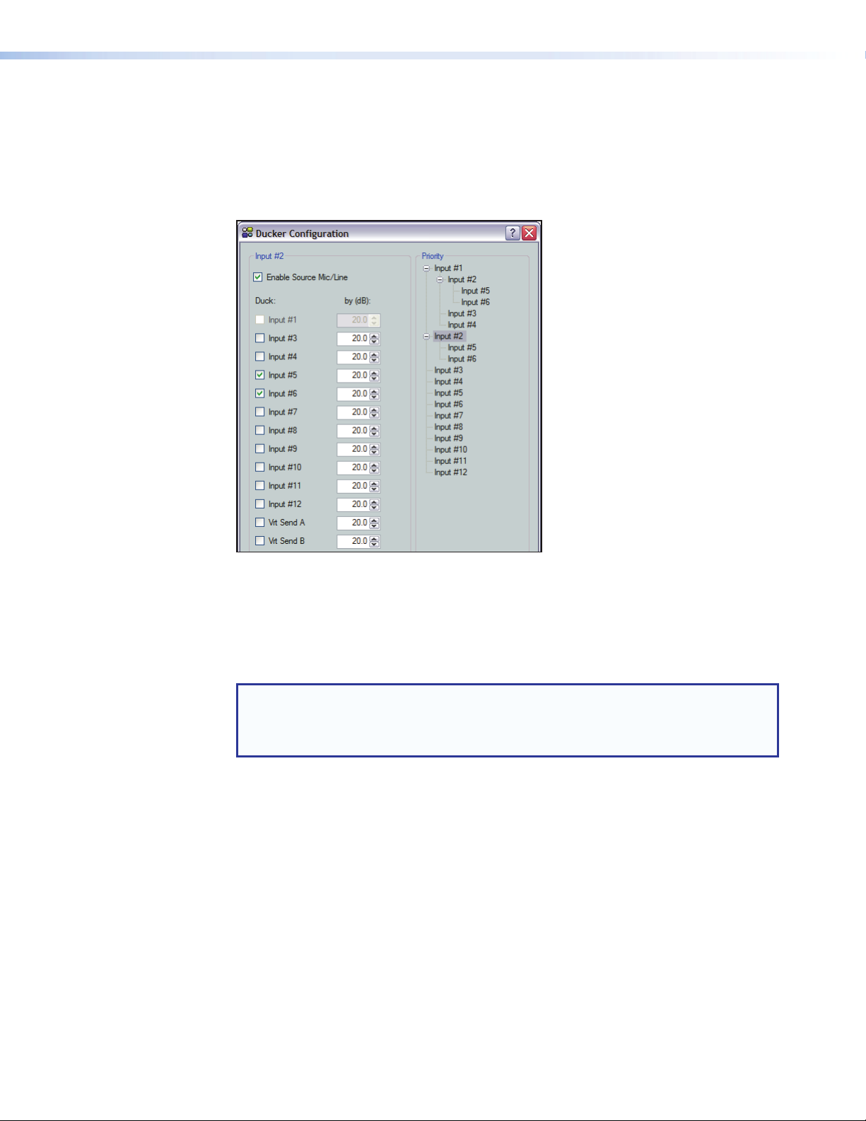
Priority
In some cases, multiple levels of ducking can be required to enable an input source to
take precedence over all but one other input.
In this example, Inputs 2 through 6 are set to duck when Input #1 has a signal above the
ducking threshold. Input#2 is set to duck inputs 5 and 6. Since Input #1 has previously
been set to duck Input #2, Input #1 is disabled to prevent contradictory priorities.
Figure 32. Ducker Configuration, Input Priority
Notice the priority tree on the right side of figure 32. The inputs are arranged by their
priority status. Input #1 has all other ducked inputs under it, therefore if a signal is
detected, it will trigger Inputs 2 through 6 to duck. If Input #2 detects a signal and there is
no signal on Input #1, Input#2 will trigger inputs 5 and 6 to duck. However if the Input#1
signal exceeds the threshold, it will then duck all inputs including Input #2.
NOTE: Ducking attenuation is not additive. When an input target is ducked,
regardless of how far down the priority line it is, the maximum attenuation is that
set for the individual input and virtual send in the “by (dB):” column near the
center of the dialog box.
See Ducker Tutorials on the next page for additional information.
DMP128 • Software Control 52
Page 59

Ducker Tutorials
The examples below are based on different input configurations. Insert a ducker from a
ducker processor block using one of the following methods:
Double-click the block,
then click Ducker
Once inserted, double-click on the ducker block to open the ducker configuration dialog
box. The Enable Mic/Line Source box is checked.
Ducking and Priority Ducking
The first inserted mic ducks all selected targets.
To set a ducking source:
1. Insert a ducking processor on input #1.
2. Open the ducker configuration dialog box and select
the desired duck targets. In this example inputs #2
through 6 are the ducking targets.
Any signal on input #1 that exceeds the ducking
threshold now ducks inputs2 through 6.
The ducking processor also provides a means to have
an additional input duck other targets using the priority
feature. The second input ducks its selected duck
targets, and can also be ducked by the first ducking
source.
Right-click the box to open context
-or-
menu, then click Insert Ducker
To set an additional ducking source:
1. Insert a ducking processor on the additional ducking source.
In this example input #2 is the second ducking source, with input#1, as shown
above, as the first source.
NOTE: Since it was previously selected as a
ducking target, Input#1 is not available as a
target of input #2.
2. Open the ducking dialog box for the input and select
the desired duck targets. In this example inputs #5
and #6 are the ducking targets of input #2.
Any signal on input #2 that exceeds the ducking
threshold now ducks inputs 5 through 6. The
ducking targets can be changed at any time by
double-clicking the input #2 ducking processor block.
Since input #2 is a target of input #1, if a signal on
input #1 exceeds the ducking threshold, inputs 2
through 6 are still ducked regardless of whether the
signal on input #2 exceeds its ducking threshold.
NOTE: No input will be ducked more than the
amount set in the by(dB): box.
DMP128 • Software Control 53
Page 60
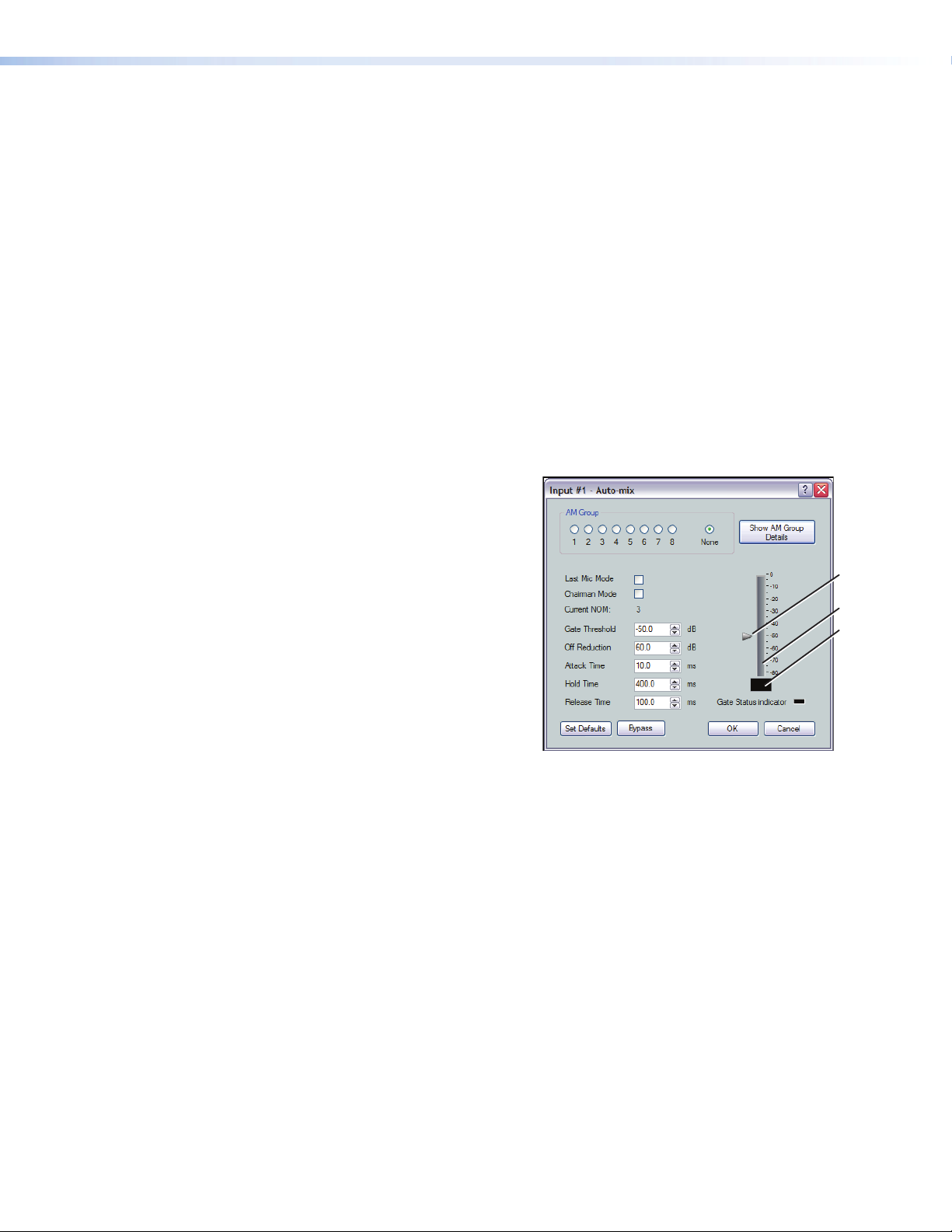
Automix (AM)
An automixer manages multiple microphone sources, gating or varying input gain
automatically. When properly set, the automixer system will improve use and performance
when multiple mics are in use. The two basic types of automixer include gated and
gain-sharing.
A gated automixer attenuates an input channel when the signal level drops below a
user-defined threshold. DSP Configurator allows the user to divide these automixers into
gating groups. Each gating group is effectively a separate automixer.
A gain sharing automixer sets a maximum room gain and splits this among all open mics,
based on their input levels. While a gain sharing mixer typically has less delay in reacting
to a speaker, gated automixers will normally produce a better noise floor.
The DMP128 allows the user to choose between a gating automixer and a gain sharing
automixer. When the number of open mics (NOM) is set to zero, the automixer is
gain-sharing. When a NOM value is provided, the automixer is gated.
The DMP128 uses an automix dialog box to configure the parameters of each channel
and select an AM group.
Automix parameters:
• AM Group (Assignment) —
Assigns the channel to a gating
group. Selections are 1 through 8.
Default is None.
• Show AM Group Details —
Accesses a dialog box that details
current groups and the parameter
member assignments to each (see
the following section).
• Last Mic Mode On/Off — Prevents
all mics from gating off at the same
time, ensuring there is always one
active mic channel. There are four
possible states:
• If not enabled on any mic input, all mics gate off.
• If enabled on all mics, the last active mic remains on.
• If enabled on one mic:
• The enabled mic remains active if it is active when all other mics gate off, or
• If the enabled mic is not active, it gates on when all other mics gate off.
• If enabled on some but not all mics, then:
• If enabled on the last active mic, this mic remains active, or
• If not enabled on the last active mic, then the first enabled mic in the group
gates on.
• Chairman Mode On/Off — One mic or multiple mics can be set to Chairman under
the Gating Priority list. When a chairman mic is gated on, all non-chairman mics are
gated off to the off reduction level.
• Current NOM — Displays the selection of the maximum number of mics that may
be gated open at any time, per gating group. The setting can be changed using the
AMGroups dialog box. Current NOM range is 1 through 12.
• Gate Threshold — The signal level below which the mic channel gates off and above
which it gates on.
Range is – 60.0dB to 0.0dB.
Default is – 50.0dB.
Gating Threshold
Indicator
Channel Level
(RMS)
Channel Level
Readout
DMP128 • Software Control 54
Page 61
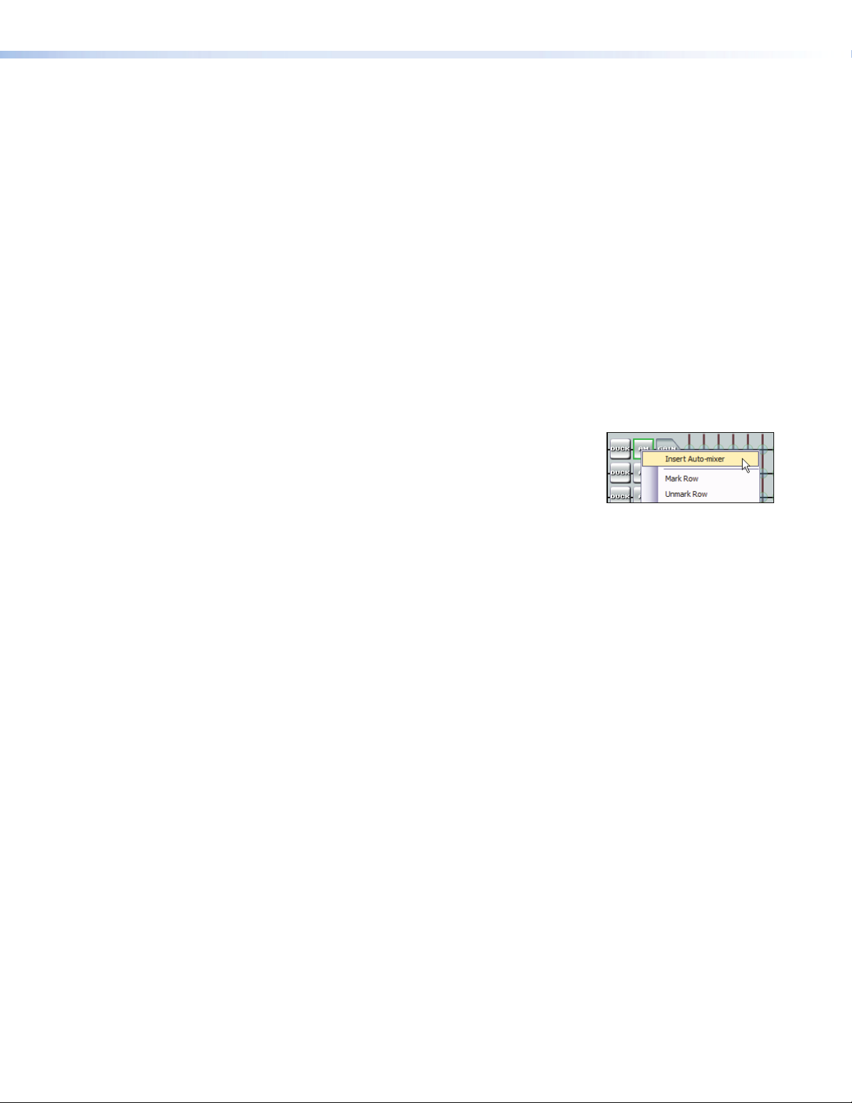
• Off Reduction — The channel attenuation when a mic channel gates off.
Range is 0.0dB to 100.0dB attenuation (0 to – 100 dB).
Default: 60.0dB.
• Attack Time — Sets the time at which gain is applied after a channel gates on.
Range is 0.0msec to 3000.0msec in 0.1 msec increments.
Default: 10.0msec.
• Hold Time — The time that a mic remains active after the signal drops below a
user-defined threshold.
Range is 0.0msec to 10000.0msec in 0.1msec increments.
Default: 400.0msec.
• Release Time — The time it takes to ramp the signal level to the Off Reduction
value when the mic channel gates off.
Range is 10.0msec to 10000.0msec in 0.1 msec increments.
Default is 100.0msec.
• Gate Status Indicator and meter — The meter provides real-time sampling of the
selected AM channel with a digital readout of the current level the meter. The indicator
lights when the channel is shut off.
To insert an automix block into a channel:
1. Insert an AM processing block in the desired channel.
Either:
• Right-click the AM block and select Insert
Automixer, or
• Double-click the AM block and select Automixer.
2. Double-click the inserted AM block to open it (see Automix parameters: on
page54).
The AM block defaults to Bypass (bypass button red). Click Bypass to toggle the AM
block to active (bypass button gray).
DMP128 • Software Control 55
Page 62
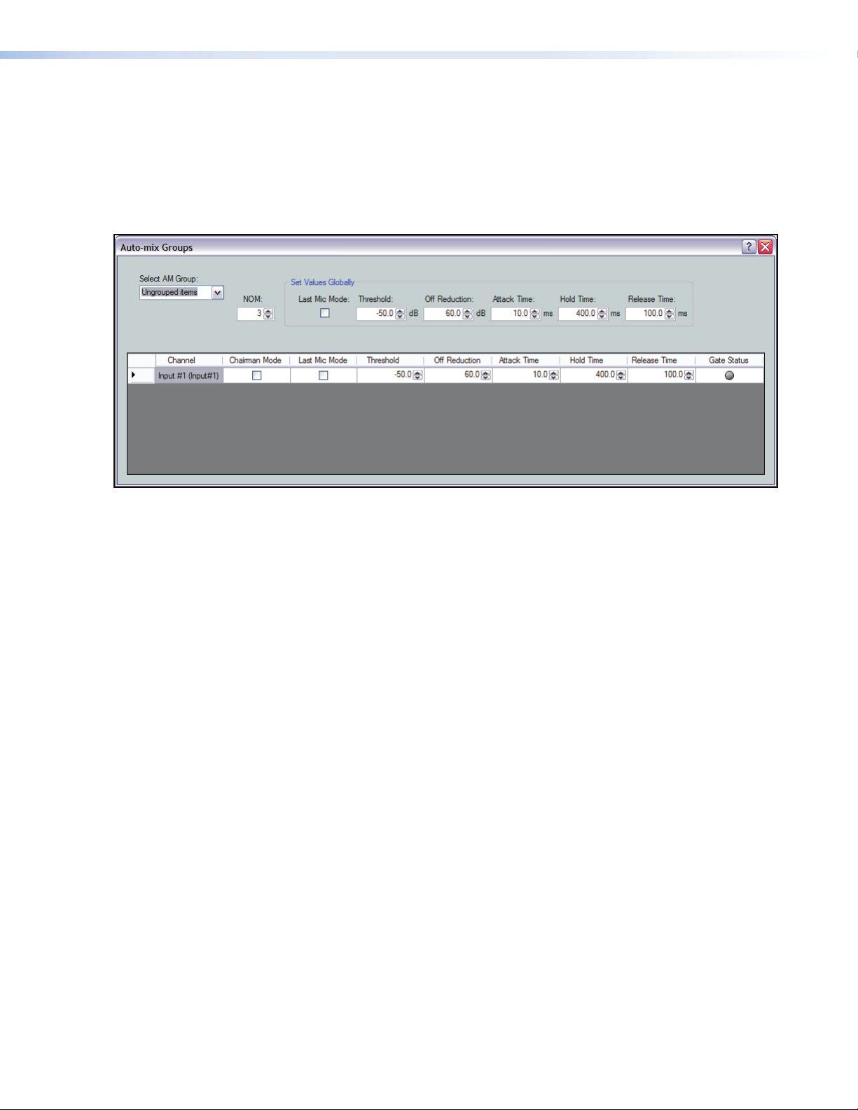
Automix Groups
Assigning individual automix channels to groups allows you to see and adjust all channels
assigned to the group on one page. The automix group dialog provides details of all
grouped and ungrouped inputs including the automix settings of each channel or mic.
This provides an overview of all channels in the selected group at a glance. Individual
settings can be changed without leaving the groups dialog. You can also select all
Ungrouped items and see the channels currently unassigned to a group.
Figure 33. Automix Groups Dialog
To Configure an Automix Group:
A channel must first have an active automix block before it can be included in an automix
group.
1. Insert an AM processing block in the desired channel. Either:
• Right-click the AM block and select Insert Automixer.
• Double-click the AM block and select Automixer.
2. Double-click the inserted AM block to open it.
3. Select the group number from a range of 1 through 8.
4. Set the parameters for the channel.
5. Repeat steps 1 through 3 for all channels in the automix group.
6. Open any AM block and click Select AM Group Details to open the automix
group configuration page.
7. Set NOM (the maximum number of gated mics) for the selected group.
8. Test the system and make adjustments as needed.
Adjustments can be made to individual automix channels using the rows by opening
each individually, or globally to all channels using the AM group details page. Observe
the Gate Status indicators to verify that channels gate on properly.
The AM Group Details dialog provides details of all grouped and ungrouped inputs
including the automix settings of each channel or mic. This allows viewing of all channels
in the selected group at a glance to provide an overview of the group. Individual settings
can be changed without leaving the groups dialog.
DMP128 • Software Control 56
Page 63
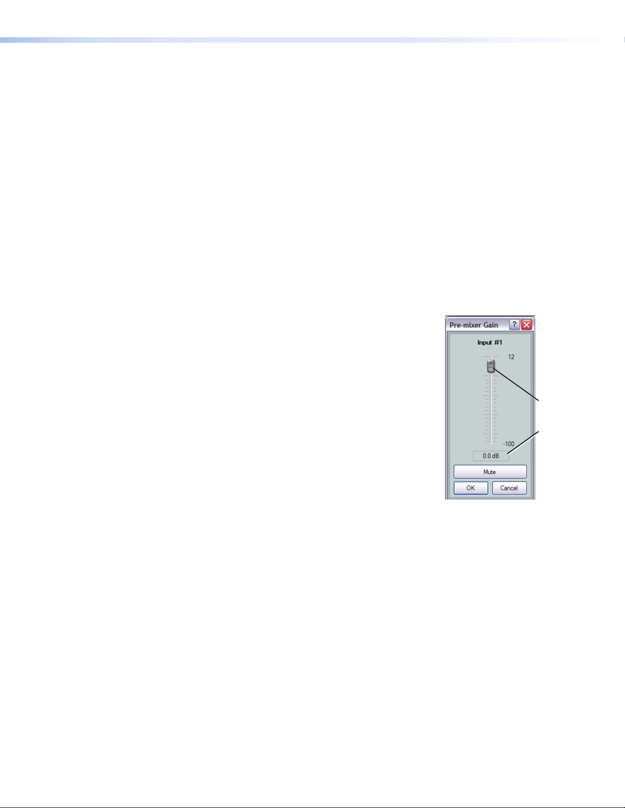
Configuring an Automix Channel
e
Before configuring automix, Extron recommends that you set proper gain staging for the
input mics. This ensures that adequate signal is provided for automix to work properly.
An automix block is inserted for each microphone, and the mic assigned to a group (see
figure 33, Automix Groups Dialog on the previous page). Setting a reasonable NOM, the
maximum number of gated mics) for the microphone group will increase intelligibility by
limiting the number of open mics that are allowed to gate on at once. A NOM of three is
recommended.
In events where a small number of talkers may need priority over other talkers (such as a
presenter at a lectern) chairman mode can be enabled on the priority input channel.
Last mic mode can minimize the frequency of gate changes. This prevents rapid switching
of input mics by, ensuring that a talker is not gated off when their speech is paused.
After the automixer is configured, be certain to set the appropriate mix-points to include
automixing.
Pre-mixer Gain (GAIN)
The pre-mixer gain control provides gain or attenuation
after the input processing signal chain. It includes a mono
long-throw fader with a – 100.0 to +12.0dB gain range,
and a current level setting readout below the fader. Fader
adjustments are in 1dB increments, while adjustments can
be entered manually to 0.1dB resolution.
Default is unmuted at unity (0.0dB) gain.
Selecting the fader handle with the mouse or clicking within
the fader area brings focus to the fader. The input signal level
can be adjusted using any of the following methods:
• Select and hold the fader handle, then drag it to desired
level in 1.0dB steps.
• Select or tab to the fader handle, then use the up/down
arrow to set the desired level in 1dB steps.
<Page Up> increases and <Page Down> decreases the
level in 5dB steps.
• Click in or tab to the level readout field. Type a new value, then press <Enter> or
<Tab> to another area.
Fader Handl
Input
Signal Level
Readout
DMP128 • Software Control 57
Page 64

Telephone RX (DMP128CP and DMP128CPAT only)
Figure 36. Telephone Rx Signal Path
The DMP128 provides a telephone interface with separate input and output signal
processing paths. The telephone input (Rx) is identical to the other input processing paths
except the AEC block is not used. See Telephone Interface on page126 for additional
information.
NOTE: The country code must be entered before connecting the DMP128 to a
phone system.
Line Output Channels
There are eight mono line output channels. Controls and processing
blocks, identical for each output channel, are described in the
following sections.
Post-mixer Trim Control (TRIM)
The post-mixer trim control provides a fader for fine adjustment of
the program material prior to the output signal chain. The trim control
has a range of – 12dB to +12dB in 0.1dB increments.
Default is unmuted at unity (0.0dB) gain.
Loudness (LOUD)
The loudness processor block, when inserted, applies
a filter compensation curve to the signal in an inverse
relationship to the output volume control setting; the
higher the output volume setting, the less compensation
is applied (see Calibrating Loudness on the next page).
The loudness processor compensates for changes in human perception to varying volume
levels by applying a filter compensation curve to the signal in an inverse relationship to
the gain control setting. The higher the gain setting, the less loudness compensation is
applied. Generally, as volume is lowered, perception of certain frequencies is progressively
diminished, returning to a more flat response as volume is increased. Loudness will boost
those diminished frequencies to the highest degree at low volume levels, decreasing the
boost as volume increases.
Bypass must be disengaged for the loudness processor to function. The bypass button
is red when engaged (loudness control defeated), and gray when disengaged (loudness
control active).
DMP128 • Software Control 58
Page 65

When bypassed, the graph displays the current filter curve as a dotted line. When bypass
is disengaged, the current filter curve is displayed as a solid line.
Figure 34. Loudness Dialog Dialog box
The Loudness dialog box contains the following elements:
1. Graph — Displays the compensation curve currently applied to the signal. These
curves are read-only, and are not adjustable from the graph.
2. Loudness Compensation slider — From a center zero-point, the user can slide to
the left for less loudness compensation (filter curve is reduced), or to the right for more
(filter curve is increased). The slider position is translated into adB value, displayed in
the compensation readout box contained in the Advanced Calibration section. The
slider has a 48dB (±24dB) range.
3. Advanced Calibration — Provides a value that corresponds to the position of the
compensation adjustment slider. The SPL box displays the summed value of the
slider and the preceding trim control.
Calibrating Loudness
The user can fine-tune the amount of loudness compensation using the compensation
adjustment slider and adjusting “by ear,” or by measuring SPL levels in a particular room,
then using the slider to adjust the loudness filter relative to the SPL of the room and
system gain structure.
Before calibrating loudness, set up the system gain structure (see Optimizing Audio
Levels on page100). A pre-recorded track of pink noise or pink noise from a signal
generator is preferable for this purpose. Program material can also be used (using familiar
material is recommended).
If using a signal generator, set it to output – 10dBu, then set the input gain of the
DSPConfigurator so the input meter reads – 20dBFS. If using a recorded source, the
pink noise should be recorded at – 20dBFS and the player output level setting control set
to maximum, or 0dB of attenuation. For program material, set the input level to meter at
approximately – 15dBFS, with peaks safely below 0dBFS.
DMP128 • Software Control 59
Page 66

Unmute the mix-point from the pink noise source to the output connected to the room
amplifier being calibrated. With the basic gain structure previously set up, loudness can be
calibrated using an SPL meter or by ear. (Loudness can also be set using an SPL meter,
then fine-tuned by ear.)
To calibrate loudness, use a sound pressure level meter set to “C” weighting:
1. Set the Loudness processor to Bypass (Bypass button red).
2. Place the meter in an average (but somewhat prominent) listening location.
3. Generate pink noise, or start the program material playback.
4. Measure the SPL in the room.
5. In the loudness dialog, adjust the slider until the value in the SPL readout box
matches the reading on the SPL meter.
NOTE: Theoretically, calibration can be performed with the output channel
volume and post-mixer gain level set to any comfortable listening level. But a
relatively loud volume (well above the ambient noise in the room) that can be
easily measured is preferred.
Loudness is now calibrated. Disengage Bypass to hear the compensation.
Alternate method to calibrate loudness:
1. Set up the procedure using steps 1 through 3 of the previous procedure.
2. Set the compensation adjustment slider to its default center position.
3. Set the output channel volume fader to 0dB (100% volume).
4. Adjust the amplifier until the SPL meter reads 90dB.
Loudness is now calibrated. This method works if 90dB is an acceptable amplifier volume
limit for the room.
Setting Loudness “By Ear”
When setting loudness by ear, it is essential the system gain structure be set up first. Sit in
an average (but somewhat prominent) listening location.
1. Set the loudness processor to Bypass.
2. Set the output volume fader in the DSPConfigurator to a relatively quiet listening level.
Filter compensation from the loudness processor is most prominent at low listening
levels. Use familiar program material set to the levels described earlier.
3. Set the Calibrate slider to 0, the center point. Disengage the loudness Bypass.
The result is a moderate enhancement to the program material, with more
accentuated bass frequencies (below 500Hz), and more brightness in the high
frequencies that carry harmonic content (above 7kHz). Engage and disengage
the Bypass switch in order to “A/B” the difference between loudness off and on,
respectively.
4. To experiment with less loudness compensation, move the loudness compensation
slider to the left (less). For more loudness compensation, move the slider to the right
(more).
5. Any adjustment made to the loudness compensation slider will carry through to all
listening levels. Set the output volume fader in the DSP Configurator to a relatively
loud listening level.
6. Engage and disengage the Bypass switch in order to “A/B” the difference between
loudness off and on. At a loud listening level, the difference should be minimal or
barely perceivable.
DMP128 • Software Control 60
Page 67

Delay Block (DLY)
The delay processor block, when inserted, provides
a means to delay the audio signal to compensate for
loudspeaker placement in situations where speakers
delivering the same signal are much farther away than
others. The delay processor block is identical to the delay processor available on
the input (see Delay (DLY) on page49). Typically the near speakers would be
delayed so that audio delivery time matches the speakers further away.
Filter Block (FILT)
The filter processor block, when first inserted, provides one of four
filter selections: High Pass, Low Pass, Bass & Treble filters and
Parametric EQ. Up to nine filters can be added to each filter block.
The output filter block is identical to the input filter processor block
except that up to nine filters total can be selected (see Filter (FILT)
on page30).
NOTE: Selecting the Bass & Treble Filter inserts two separate filters.
Dynamics Block (DYN)
A dynamics processor block, when inserted,
provides one of four dynamics processors:
AGC, Compressor, Limiter, and Noise Gate.
The available processors are identical to the
processors available on the input dynamics
processor block and described in (see
Dynamics (DYN) on page44).
DMP128 • Software Control 61
Page 68

Volume Control (VOL)
Each output channel volume block provides a mono long-throw
fader and a volume setting readout (indB) below the fader. Volume
level is adjustable with the slider or by entering the desired level
directly into the volume setting readout in 0.1dB increments.
Clicking the fader handle or clicking within the fader area brings
focus to the fader. The input signal level can be adjusted using any
of the following methods:
• Click and hold the fader handle, then drag it to desired level in
1.0dB steps.
• Click or <tab> to the fader handle, then use the
<up> and <down> arrow keys to change the desired level
in 1dB steps. <PageUp> (increase) and <Page Down>
(decrease) the level in 5dB steps.
• Click in or tab to the level readout field. Type a new value, then
press <Enter> or <Tab> to another area.
The default setting is unmuted, at 0dB attenuation. A peak meter
displays the real-time audio level from – 60 to 0dBFS.
Click OK to accept settings and close the dialog box. Click Cancel to ignore changes
and close the dialog box.
The output volume control provides level control for each output. The output control is a
trim control adjustable from – 100.0to 0dB. The default setting is unity gain (0.0dB).
The Polarity button, allows the polarity of the wires connected to the audio connectors
(+/tip and -/ring) to be flipped in order to easily correct for miswired connectors.
The Mute button silences the post-meter audio output. When the audio output is muted,
the mute button lights red, and red indicators in the block turn on.
If the output has been grouped with other inputs or outputs, the group number is
indicated on the right side of this button (see Line Output Channels on page58).
Telephone Tx (DMP128CP and DMP128CPAT only)
Figure 35. Telephone Tx Signal Path
The DMP128 provides a telephone interface with separate input and output signal
processing paths. The telephone output (Tx) is identical to the other output processing
paths. All signals routed to the Telephone Tx are also available on output 8.
See Telephone Interface on page126 for additional information.
NOTE: The country code must be entered before connecting the DMP128 to a
phone system (see Telephone Configuration on page126).
DMP128 • Software Control 62
Page 69

Virtual Bus Returns
Virtual Bus Returns, A-D
There are eight mono virtual bus return inputs, fed by the virtual sends. Channel controls
and processing blocks described in the sub-sections that follow are identical for each
virtual bus return channel.
The eight returns are divided into two similar paths. Channels A through D contain a
feedback suppression processing block in each channel. Channels E through H are
identical except there are no feedback processing blocks.
The virtual bus is used when additional processing of an input signal is required. It is also
useful to apply identical filtering, dynamics processing, loudness compensation, or signal
gain/attenuation to multiple inputs.
Feedback Suppressor (FBS)
The Feedback Suppressor (FBS) is used when there is indication of feedback during
live operation. Dynamic filters automatically detect feedback on a live mic channel, and
engage a set of up to 5 fixed and 15 dynamic filters to counteract the frequency peaks at
the detected feedback frequency. Up to 15 separate filters can be employed at any time.
The 15 filters act in a FIFO, or first in, first out rotation. If all 15 filters are employed, when
an additional feedback frequency is detected it overwrites the first detected feedback
frequency and so on.
To avoid a new feedback frequency overwriting a previously detected one, up to five of
the dynamic feedback frequencies can be placed into fixed filters. Once written into the
fixed filters, the feedback frequency can only be overwritten by manually writing a new
frequency to the filter.
The FBS dialog box has three tabs; Settings, Dynamic Filters and
Fixed Filters. Global settings and view options are controlled from the Settings
tab. Dynamic to fixed filter allocations are handled from the Dynamic Filters tab. Filter
parameters can be modified from the Fixed Filters tab.
DMP128 • Software Control 63
Page 70

The FBS dialog box provides the following global buttons:
• Clear All — Clears all dynamic filter settings.
• Lock — Locks the dynamic filters to current settings, preventing automatic updates.
This temporary mode is useful while testing the system, or during the time when
dynamic filters are being converted to fixed filters. When the FBS dialog box is closed,
lock mode is automatically disengaged.
• Bypass FBS — Turns off feedback detection when engaged (button is red). Only the
dynamic filters are bypassed. Fixed filters remain active.
• Set Defaults — Click once to return the FBS to default settings.
Figure 37. Feedback Suppressor
DMP128 • Software Control 64
Page 71

FBS Settings Tab
The Settings tab enables selection of the feedback suppressor parameters.
• For Composite View show: — The graph view is set by one of three radio buttons:
• Only Dynamic FBS Filters
• Only Fixed FBS Filters
• Dynamic & Fixed FBS Filters (default)
• Mode: Q — Adjusts the notch filter Q used by dynamic filters. Similar to Q on the
parametric equalizers, Q changes the bandwidth of the filter. The default setting can
be modified in Tools > Options. The range is from 5 to 65. Larger values provide
less change to the audio frequency response while lower values may provide greater
feedback suppression but with more possible impact to the tonal response of the
source audio.
Suggested values for specific applications are:
Q Value Application
7 Voice with considerable feedback potential
30 Voice with less feedback potential
65 Music with minimal feedback potential
• Attack Time — Sets the time at which dynamic filters are generated after feedback
detection. A longer attack time (greater than 200 ms) reduces the chance that music
or audio content will trigger the dynamic filters to respond. A shorter attack time (less
than 2 ms) reduces the time between when feedback is detected and suppressed.
• Hold Time — Expressed in hours:minutes:seconds up to 9 hours. Hold time sets
the time a dynamic filter setting persists before the filter is cleared. When hold time is
disabled (checkbox cleared) dynamic filters persist indefinitely unless cleared manually
or the device is power cycled.
Figure 38. FBS Settings Tab
DMP128 • Software Control 65
Page 72

FBS Dynamic Filters Tab
abc
This dialog contains the fifteen dynamic filters, with a scroll bar to display filters hidden
due to the dialog box size.
Dynamic filters are cut only notch filters, providing attenuation up to 30dB at the specified
Q. The default Q is set in the Tools > Options menu, but can be changed on the
settings tab prior to engaging the FBS dynamic filters.
NOTE: Changing the Q setting in the options menu after dynamic filters have been
generated clears all dynamic filters.
Figure 39. FBS Dynamic Filters Tab
Frequency and cut values are read only. Dynamic filters are in auto-detect mode when the
FBS block is active (see figure 39, a; Bypass FBS off). If testing reaches a point where no
further changes are desired, the lock button can be engaged. The lock mode of operation
is temporary, and is intended to be used during setup of the FBS. When the FBS dialog
box is closed, lock mode is automatically disengaged.
If there are specific dynamic filters that you want to assure are not overwritten, press the
Move to Fixed button (see figure 39, b) to write the designated filter settings to the first
available filter in the Fixed Filter tab.
NOTE: When a dynamic filter setting is moved to the fixed filter, it automatically
clears that frequency from the dynamic filter.
The Clear button (see figure 39, c) removes a detected frequency from the
corresponding dynamic filter. A cleared filter reverts to auto-detect mode unless Lock
mode is engaged.
DMP128 • Software Control 66
Page 73
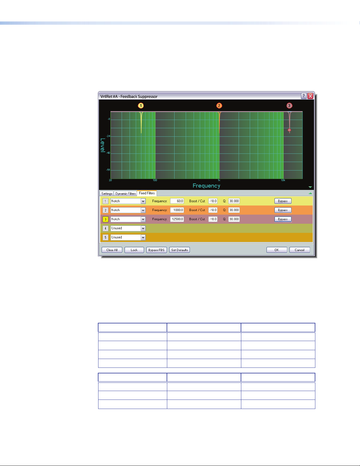
FBS Fixed Filters Tab
Fixed filters are notch filters with an adjustable center frequency and Q, and up to 30dB
of cut. The fixed filters are typically set by converting dynamic filters to fixed, however
adjustments to filter parameters can be manually made from the Fixed Filters tab.
Fixed Filters are inactive and the filter type is set to Unused by default (see rows 4 and 5
in figure 40).
Figure 40. FBS Fixed Filters Tab
No filter parameters are displayed when the filter type is set to Unused. As a filter is
moved to the fixed filter tab from a dynamic filter, the filter becomes active and displays
Notch as the filter type. The parameters copied from the dynamic filter are displayed in
the same line. Once a fixed filter is active, settings can be modified or adjusted as needed.
Fixed filters can also be individually bypassed by clicking Bypass.
FBS Settings Ranges and Fixed Filter Defaults
FBS Parameter Settings Range Default Setting
Frequency 20 Hz to 20 kHz N/A
Q 5.000 to 65.000 30.000
Attack Time 0.0 ms to 1000.0 ms 10.0 ms
Filter Hold Time 0 seconds to 9 hours 00:00:00; Disabled
Fixed Filter Parameter Settings Range Default Setting
Frequency 20 Hz to 20 kHz 1000.0 Hz
Q 1.000 to 65.000 30.000
Cut Up to 30dB cut 0.0dB
DMP128 • Software Control 67
Page 74

Filter (FILT)
Filter function and interface is identical to the mic/line input channel Filter block except
that only three filters are provided (see Filter (FILT) on page30).
Dynamics (DYN)
There is one dynamics processor block available on each virtual path. Dynamics function
and interface is identical to the mic/line input channel Dynamics block,
(see Dynamics (DYN) on page44).
Loudness (LOUD)
There is one loudness processor available on each virtual path. The loudness function and
interface is identical to the Output channel Loudness block (see Loudness (LOUD) on
page58).
Bypass must be disengaged for the loudness processor to function. The bypass button
is red when engaged (loudness control defeated), and gray when disengaged (loudness
control active).
Delay (DLY)
Audio Delay syncs audio to video or to time-align speakers that are placed at different
distances from the listener. The Delay function and interface is identical to the input
channel delay block (see Delay (DLY) on page49).
Gain (GAIN)
Each virtual input channel gain block provides a mono long-throw fader with a – 100.0
to +12.0dB gain range, and a level setting readout below the fader. Fader behavior is
identical to the Pre-mix-point gain block, described in the mic/line input section
(see Pre-mixer Gain (GAIN) on page57). Fader adjustments are in 1dB increments,
while adjustments can be entered manually to 0.1dB resolution.
Default is unmuted at unity (0.0dB) gain.
Virtual Bus Returns, E-H
There are four additional mono virtual bus return inputs. Virtual Bus Returns E through H
are identical to A through D except there are no feedback processors.
As with the virtual bus returns A through D, these returns are used when additional
processing of an input signal is required. It is also useful to apply identical filtering,
dynamics processing, loudness compensation, or signal gain/attenuation to multiple
inputs.
DMP128 • Software Control 68
Page 75

Output Mix Matrix
The DSP architecture contains an output mix matrix that connects all inputs to the line
outputs, a virtual send mix matrix that connects all inputs to the virtual outputs, and
an expansion (EXP) output mix matrix that connects the mic/line inputs and virtual bus
returns to the expansion outputs (see figure 41 on the next page).
The output mix matrix sets mix levels from the post processing inputs and post
processing virtual returns, to each line output bus. The mix-point behavior is shown on
page 73.
Each mic/line input and virtual bus return is connected to a mix-point for each of the eight
line outputs. In general, mix levels are set relative to each other, achieving a desired blend
of input signals at an optimal output level, close to, but not exceeding 0dBFS at the line
output volume block level meter (while accounting for processing that may occur in the
line output signal chain).
NOTE: Although the virtual Output and return lines, A through H, are shown as
end points on the DSPConfigurator screen, they are connected A to A, B to B,
CtoC, D to D, E to E, F to F, G to G and H to H. These connections cannot be
changed.
DMP128 • Software Control 69
Page 76

Outputs
Output
Virtual Send
Expansion Output
Mix Matrix
Mix Matrix
Mix Matrix
Inputs
Virtual Returns
Expansion Inputs
1 - 8
1 2
1 2
1 2
3 4 5 6 7 8
3 4 5 6 7
3 4 5 6 7 8
8
Virtual Send Bus Expansion Outputs
C D E
F G
A B
A B
C D E
H
1 2
F G
H
3 4 5 6 7
8
10
11
12
13
14
15
16
Expansion Outputs
9
9 - 16
Figure 41. Overview of DSP128 Mix-matrix
DMP128 • Software Control 70
Page 77
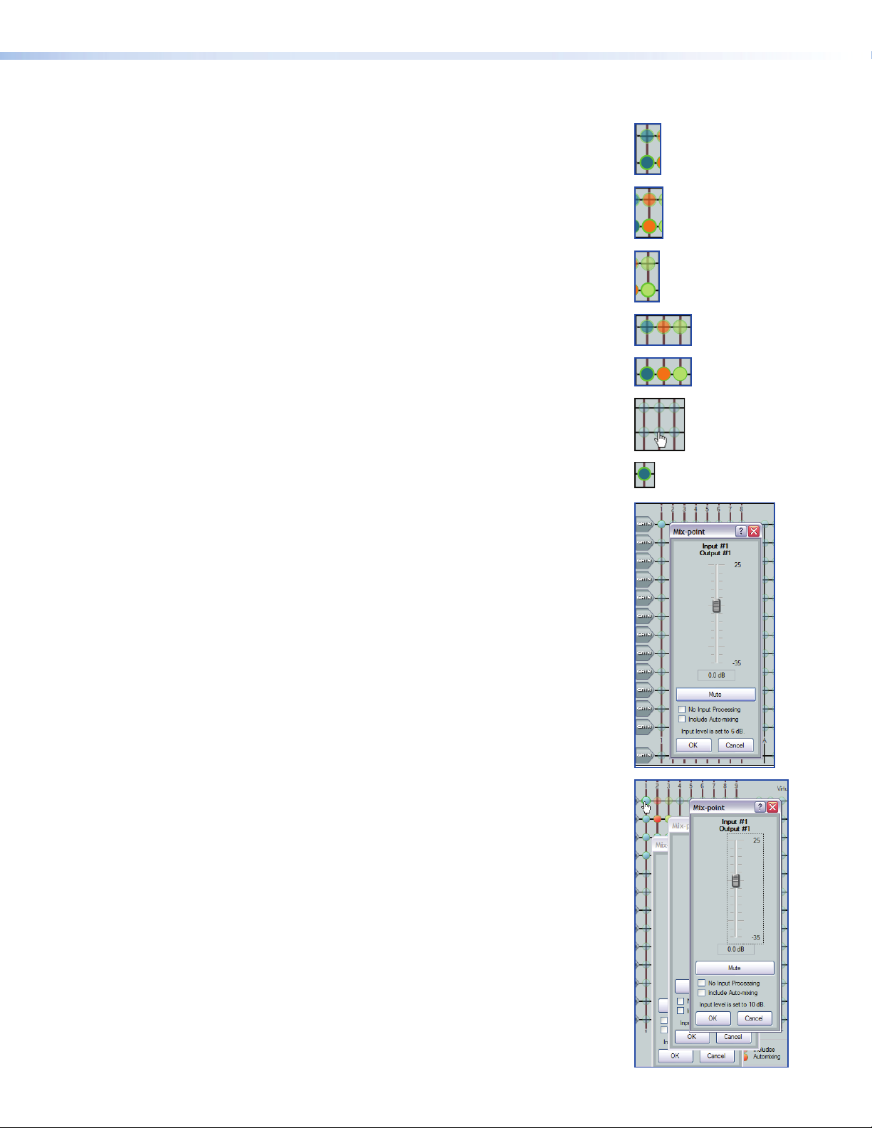
Mix-point Behavior:
Mix-point color — There are three colors of mix-points:
Teal indicates standard processing (default).
Orange indicates that the signal chain includes an
auto-mix processor.
Green indicates that all signal processing has been bypassed, post
input gain control.
No mix information — A faint transparent circle (teal, green, or orange) on
the mix-point indicates that it is muted (contains no mix information).
Mix information — A solid circle indicates that the mix-point contains mix
information (the mix-point is unmuted).
Mouse-over — The cursor changes to a hand when a mouse-over occurs
at a mix-point whether the mix-point contains mix information or not.
Single-click — A single-click (click) brings focus to (selects) the mix-point,
indicated by a dark green outline around the circle.
Double-click — A double-click opens the mix-point dialog box. The focus
outline turns light green to indicate the open dialog box. If the mix-point is
muted, the mix-point circle is gray and the Mute button in the dialog box is
red.
If unmuted, the bubble is teal and the mute button in the dialog box is
normal (typically gray for most color schemes).
Multiple open dialog boxes — When multiple mix-point dialog boxes
are open, the mix-point for the most recently opened dialog box receives
the light green focus circle, while previously opened dialog boxes
relinquish their focus. Focus can be returned by a click on a previously
opened dialog box, or by double-clicking a mix-point.
DMP128 • Software Control 71
Page 78
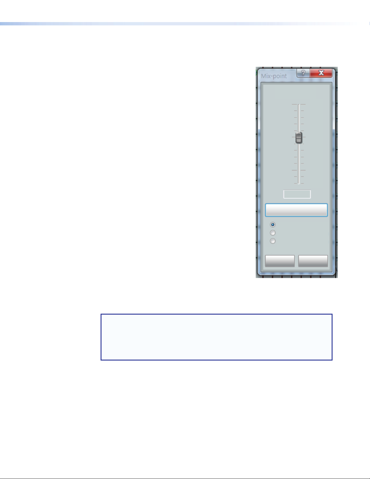
Click a mix-point to bring focus to that mix-point. A circle appears around the teal
mix-point, which remains transparent. Double-click a mix-point to open a configuration
dialog box with the following components:
• Mono Fader — Sets the signal level from the
selected input to the output bus. Gain range is -35dB
to +25dB. Fader behavior is identical to the input
channel gain block described in the mic/line input
section with the exception that course adjustment
(<PageUp> and <Page Down>) increases or
Mix-point
Input #1
Output #1
25
decreases in 5dB increments.
• Mute — Mutes and unmutes the signal to the output
bus. The mix-point ball is transparent when muted
(Mute button red) and solid when unmuted.
• No Automixing — When selected, bypasses all
automix channel inputs. The mix-point is teal.
• Includes Automixing — When selected, includes
the automix channel input. The mix-point turns
solid orange when the mix-point is unmuted and
transparent orange when muted.
• No Input Processing — When checked, bypasses
0.0 dB
-35
all processing for the preceding input string. This
allows a direct comparison of sound between the
Mute
unprocessed signal and fully processed. The mix-point
turns green when unmuted and transparent green
when muted. Default is cleared.
• OK/Cancel — click OK to accept changes and close
the box. Cancel ignores changes and closes the
No Automixing
Includes Automixing
No Input Processing
Input level is set to 0 dB.
dialog box.
The title above the fader reflects the input and output
OK Cancel
channel names for the mix-point. The example on the right
is the Input #1 to Output #1 mix-point set to 0.0dB.
The input level text below the mute button indicates the input level setting for the input
gain control or mute status of the selected input signal path, in this example 0db.
Only when the mix-point is unmuted does the circle become solid.
NOTE: The No Input Processing and Includes Auto-mixing buttons
are mutually exclusive. You cannot select both. If you are including an automix
channel in the signal path, when you select No Input Processing, Include
Auto-mixing clears and does not turn back on even when No Input
Processing is unselected. If you want to continue to have an automixing channel
in the signal path, it must be selected again.
DMP128 • Software Control 72
Page 79
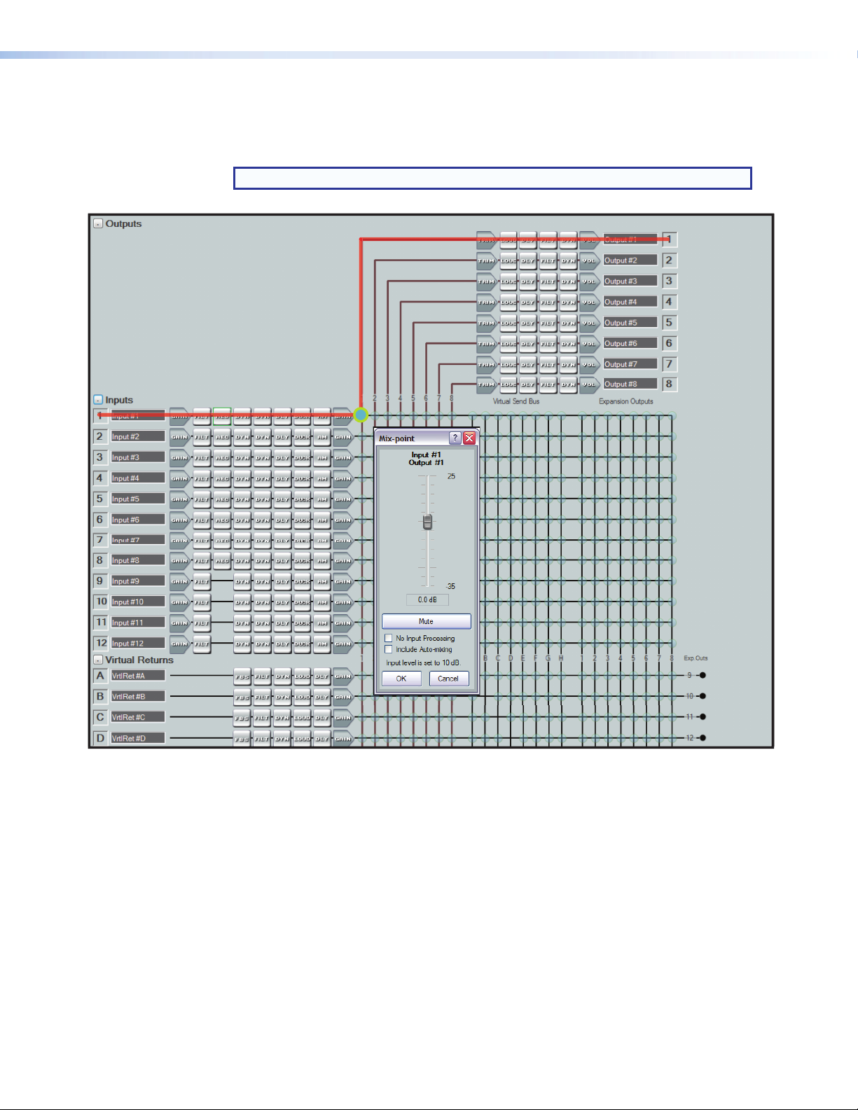
Mix-point Examples
In order to better understand how mix-points work, the following diagrams provide
examples of mixes.
NOTE: To simplify the diagrams not all input and output lines are shown.
Figure 42. Input 1 to Output 1
In the first example (see figure 42) input audio from Input 1 is processed and arrives at the
output 1 matrix mix-point. Double-click the mix-point to open the dialog box. When the
mix-point is unmuted, the mix junction turns teal with a light green circle to indicate the
open mix-point dialog box is the focus, and the signal is routed to output1.
The mix level can be adjusted using the slider or by direct input of a value between – 35.0
and 25.0dB into the dialog box below the slider.
DMP128 • Software Control 73
Page 80
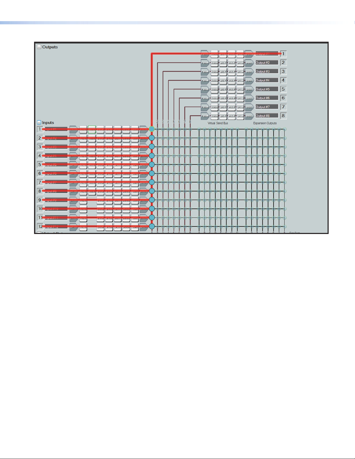
Figure 43. All Inputs to Output 1
In the next example (see figure 43), input audio from all twelve mic/line inputs are
processed individually and arrive at their output 1 mix-points. As each mix-point mute
button is released, its output 1 mix-point junction turns teal, and the signals are all routed
to Output 1. Since all the signals are now on output signal line 1, open the individual
mix-points to adjust signal levels for the desired balance. Open the output 1 trim,
processing, or volume to change the signal levels or effects for the signals coming from
the mix-points.
In this manner, any single input, or any number of inputs can be routed to any single
output or any number of outputs.
DMP128 • Software Control 74
Page 81

Figure 44. Input 1 to All Outputs
In the example in figure 44, input 1 has been routed to all eight outputs by unmuting
the mix-point for Input 1 for each output (1 through 8) bus. The example also shows the
mix-point for output four with input processing bypassed (green) and the mix-point for
output eight with active automix.
DMP128 • Software Control 75
Page 82

Virtual Send Bus Mix Matrix
The DSP architecture contains a Virtual Send Bus mix matrix that connects the inputs and
virtual bus return signals to the virtual sends. There is an additional mix matrix to route
EXP input signals to the virtual sends.
The DSPConfigurator main screen provides control of the virtual bus mix matrix, used
to set levels from input signals to the virtual sends. Each of the twelve mic/line and eight
virtual return inputs are connected to a mix-point for virtual bus A through H (and the
EXP inputs). Each mix-point is muted and set to 0.0dB (unity gain) by default. In general,
mix levels are set relative to each other, achieving a desired blend of input signals at an
optimal level close to, but not exceeding 0dBFS at the output volume level meter.
The virtual mix matrix contains a section (see figure 45 below) that allow the virtual
bus returns to be routed back to the virtual bus matrix for further processing using an
additional virtual bus processing block. To prevent feedback loops, a virtual channel is
prevented from being routed back to itself by eliminating the mix-point that would allow
that to occur.
In situations requiring extra processing, the virtual bus return output is routed back to the
virtual bus send mix matrix, which then routes the signal back to a processing signal chain
other than the one it was routed from.
Virtual Send
Bus Mix Matrix
a
Virtual Send Bus Mix-points
(from Mic/Line Inputs)
b
Virtual Send Bus Mix-points
(from Virtual Bus Returns)
c
EXP Inputs to Virtual Bus
Sends
Figure 45. Virtual Bus Mix Matrix (EXP inputs 9-16 not shown)
DMP128 • Software Control 76
Page 83

In the example in figure 46 below, input 1 is sent to the virtual send bus by muting all
eight signals on the Input1 output mix-points and unmuting virtual send bus output 1.
The virtual bus now serves as additional signal processing for the input. The signal routes
from virtual send A through the virtual busA signal chain before it is sent to the virtual bus
return mix-point and finally to output 1.
This configuration is useful when more than one input requires identical processing.
For example if all inputs were normalized but required a uniform gain to bring them up
to adequate output levels, rather than changing each pre-mix gain control by a similar
amount, all twelve inputs can be routed to a virtual bus (in this case virtual bus A). Then,
using the virtual bus A return gain control, a single adjustment can apply the same gain to
all twelve inputs before sending the signal to the desired output.
In other cases, when multiple mic inputs are mixed with program material, only the
program material might require loudness contouring. So the mics are routed directly to the
output but the program material input is routed to the virtual bus return where loudness
contouring is applied. The program material is then routed to the same output as the
mics.
Figure 46. Input 1 to Virtual Bus A
DMP128 • Software Control 77
Page 84
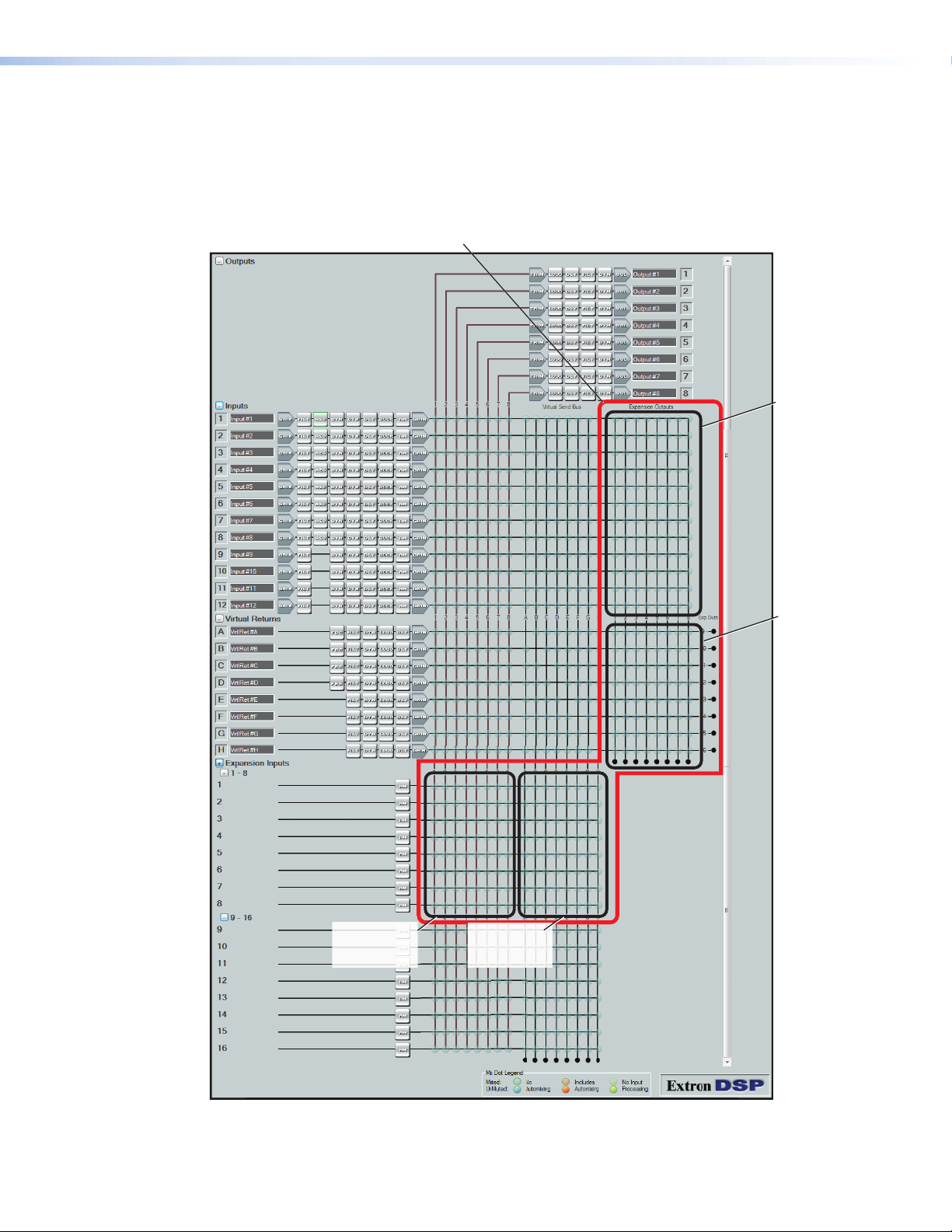
Expansion Outputs Mix Matrix
The DSP architecture contains a third mix matrix that supports connection and control of
a second DMP128 using the included shielded CAT 6 cable. The output connects the
mic/line inputs and virtual returns to the Expansion Outputs. The DSPConfigurator main
screen provides all necessary control of the mix matrix.
Expansion Outputs
Mix Matrix
Inputs to
EXP Sends
(1-8)
Virtual Returns
to
EXP Sends
(9-16 only)
Exp Inputs
to
Outputs
EXP Inputs
to
Virtual Sends
Figure 47. Expansion Bus Mix Matrix
DMP128 • Software Control 78
Page 85
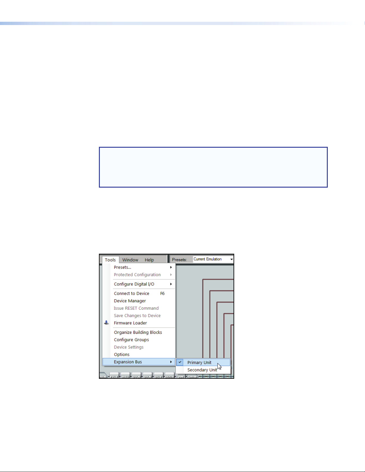
Extron EXP Bus
Connecting the EXP Ports
Using the Extron Expansion port (EXP), two DMP128 units can be connected together for
bi-directional communication of 16 channels of audio.
The expansion bus mix matrix can route any or all of the mic/line inputs to any or all of
the expansion outs (1 through 8). In addtion, there are eight channels (expansion outs 9
through 16) directly connected to the virtual bus returns.
Minimal setup is required for EXP port communications. One DMP128 must be set as the
Primary Unit, and the other as the Secondary Unit to synchronize the sampling clocks of
the two units. This has no bearing on how audio is transported from unit to unit, making it
unimportant which unit is set to primary.
NOTE: You can connect a DMP 128 AT to a non-AT unit by the EXP ports, however
be aware that the AT unit defaults to the primary unit and cannot be changed.
You cannot connect a DMP 128 AT model to another AT model by the EXP ports
because there is no option to set one as primary and the other as secondary as
required.
To enable the expansion bus between two units:
The EXP bus requires one device be configured as the primary unit and the other as the
secondary unit. The tools menu is used to configure the connection.
1. Power on both units. Open DSP Configurator and connect Live to the first unit.
From the main menu, select Tools>Expansion Bus>Primary Unit.
A checkmark appears beside the active unit.
Figure 48. Expansion Bus Unit Selection
2. Select Tools>Connect to Device and connect Live to the second unit.
3. Select Tools>Expansion Bus>Secondary Unit.
A checkmark appears beside Secondary Unit.
DMP128 • Software Control 79
Page 86

4. Connect the EXP port of one unit to the EXP port of a second unit
34
using the included shielded (or similar) CAT 6 cable.
NOTE: The front panel EXP LED indicates device to device
connection and configuration status as follows:
• (non-AT models)
• Off — The unit is not connected to a second
DMP128.
• On — The unit is connected to another DMP128 and
configured as the primary unit.
• Blinking — The unit is connected to another
DMP128 and is currently configured as the secondary
unit.
• (AT Models)
• Off — Dante device is not responding.
• On — The EXP port is connected to a non-AT
DMP128 and configured as the primary unit.
• Blinking — The EXP port is not connected.
Using the Expansion Bus
After configuration and connection, the two units have 16x16 channels of bi-directional
audio communication.
• The expansion bus from the primary unit (see figure 49, a) sends audio to Expansion
inputs 1–16 of the secondary unit (see figure 49, b).
• At the same time, the expansion bus from the secondary unit sends audio to
Expansion inputs 1–16 of the primary unit.
12
RS-232
TxRx
RS-232
TxRx
LAN
EXP
RESET
LAN
EXP
RESET
1A
Figure 49. EXP Bus Connections
EXP Bus Connection
Primary (1) to Secondary (2)
1
1B
0
1
2
2A
3
4
5
6
DMP128 • Software Control 80
2B
2
Page 87
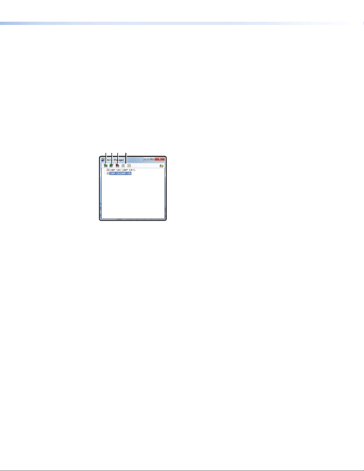
Device Manager
abcd
The mic/line inputs and the virtual bus returns make up the expansion bus mix matrix that
feed EXP outputs 1 through 8 (see figure 49, Ä) of the primary unit. They are connected
to EXPinputs 1 through 8 of the secondary unit (see figure 49, Å), respectively.
The primary unit EXP outputs 9–16 (see figure 49, Ç) are direct feeds from virtual bus
returns A–H(post processing). They are connected to EXP inputs 9 through 16 of the
secondary unit (see figure 49, É)
When multiple DMP128s are connected, use the Device Manager to select the device
open in the DSPConfigurator dialog box.
From the menu bar, select Tools > Device Manager to open the device manager
dialog shown in figure 50.
Figure 50. Device Manager Dialog
The icons function as follows:
a Add Device – Brings up the opening DSP Configurator connection dialog allowing
the selection of the model number of the secondary device.
b Clone Device – Provides the option to duplicate the primary device configuration
to the connected secondary device.
c Delete Device – Deletes the highlighted device
d Expand or Collapse Device – If the device connection tree is collapsed, allows
it to be expanded. If the device tree is collapsed, expands it.
The icons for the devices are unavailable if the device is offline.
AT (Dante) Bus
For connection and software operation of the AT bus and Dante Controller software, see
Dante Controller Software Installation on page113.
DMP128 • Software Control 81
Page 88

Group Masters
Group Members
Grouped Controls
There are 32 Group Masters that can each be configured to simultaneously control up
to 16 group members. Group masters are configured in DSP Configurator and saved in
the device. Working in emulate mode, group masters are saved in a configuration file and
pushed to the device upon connection.
A group master can either be a gain control or a mute control. Only one control type
can be selected as group members for control by a group master. For example, a group
master can be configured to control post-matrix gain levels, but not post-matrix gains plus
input gain block. A group member can, however, be controlled by multiple group masters.
It is recommended this feature be used cautiously, as “overlapping” membership can
quickly become unmanageable.
Group master gain controls can send specific values, such as those sent by a fader
control. Group master gain can also be set by increment and decrement (see Tools on
page86).
Once a group has been created, the group members — the individual controls that
comprise the group — update to indicate they are now part of a group. Group members
can be controlled individually, allowing for relative levels between members to be
fine-tuned. Group member levels can also be set by a preset recall.
Grouping is convenient when multiple controls require muting at the same time or when
multiple signal levels need to be increased or decreased simultaneously. For example, in
a system with several audio outputs dedicated to a single room, the operator can want all
outputs to change at the same rate and at the same time. The output 1 through 4 volume
controls are grouped into a master so that one group volume control, controls the volume
throughout the room.
For further flexibility, individual volume controls in the group are set for an output level
based on its use. When the group fader moves, all four output control faders move in
tandem while retaining their levels relative to each other.
Grouped faders move together at relative levels to the top or bottom of their travel (see
figure 51, next page). If one fader reaches the limit of its travel first, it retains that position
while the other faders continue to travel. When the grouped faders travel in the reverse
direction, the fader that was at its limit reverts to its position relative to the other faders.
NOTE: If a block was previously muted when the group mute is activated, that block
remains muted when the group mute is released.
TIP: When including a control in multiple groups, do so with care. Overlapping
group membership can quickly become unmanageable. Use presets to set
individual faders to known levels.
DMP128 • Software Control 82
Page 89

Figure 51. Sample Gain Group Master and Associated Gain Controls
Mute controls within the blocks can also be grouped (see figure 52).
Figure 52. Sample Mute Group Master and Muted Outputs
DMP128 • Software Control 83
Page 90
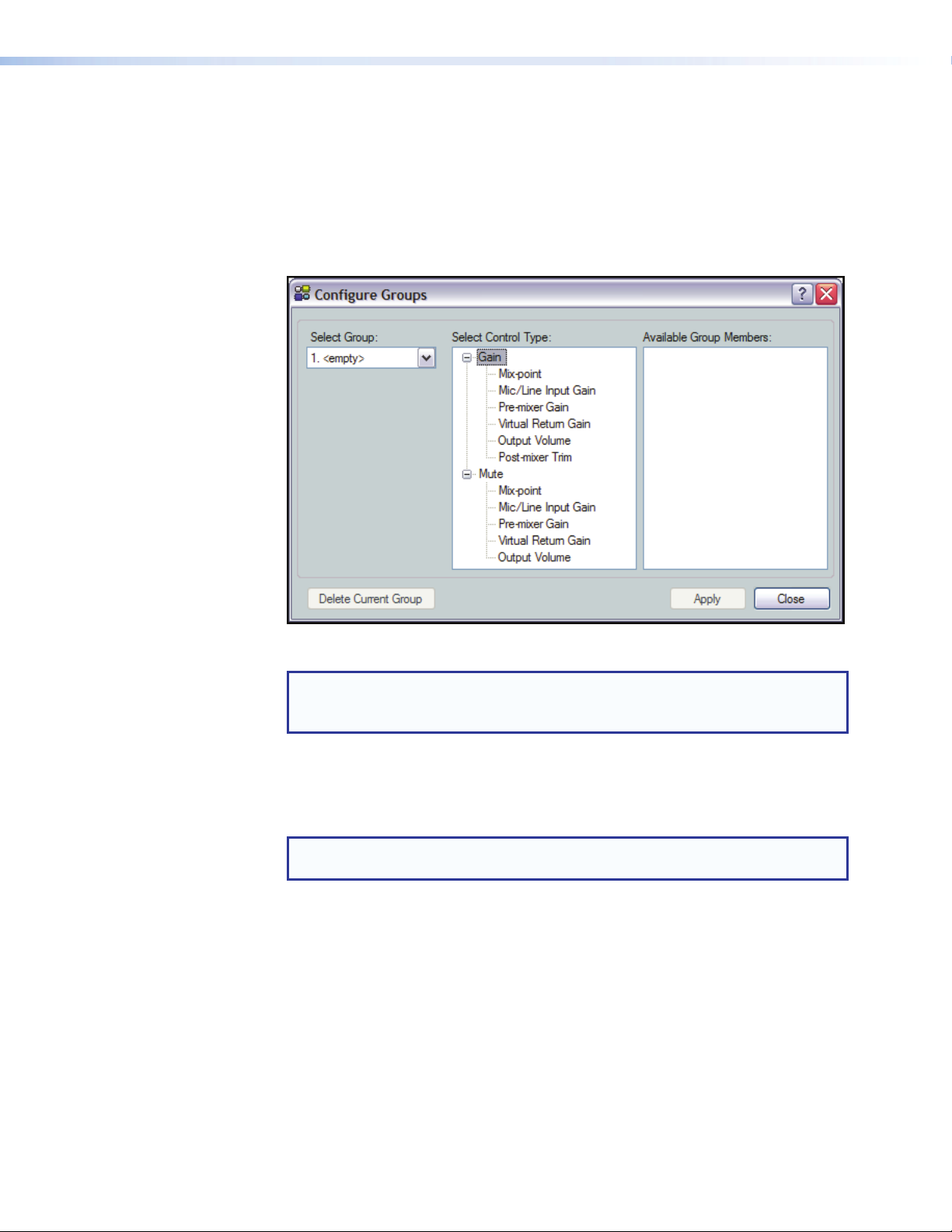
Configuring a Group Master
To configure a group:
1. Click Tools > Configure Groups (see figure 52 on the previous page) to open the
Configure Groups dialog.
or click View > Group Controls > Add a Group.
2. Click the Select Group drop-down list (see figure 53). The list defaults to the first
empty group. Select an empty group, or an existing group to overwrite.
Figure 53. Configure Groups, Add Group Dialog Box
NOTE: <empty> groups have no group members assigned. Numbered groups
(such as <Group #1>) have controls assigned that may be overwritten if
3. In the Select Control Type panel, expand the tree for the type of control,
4. In the Available Group Members section, click the checkbox to make appropriate
5. Click Apply to create or configure the group.
6. Repeat steps 2 through 5 to create or configure up to 32 groups.
7. Click Close to exit the configure groups dialog.
selected.
Gain or Mute, then select the desired control type. When a selection is made, the
Available Group Members section populates with all possible members for the
selected control type.
NOTE: Potential group members in step 4 that are already assigned to a
different group are displayed in blue.
selections. When a plus sign (+) exists, click to expand the tree and select individual
controls. Up to 16 group members can be added.
DMP128 • Software Control 84
Page 91

Deleting a Group Master
To delete a group:
1. Click Tools > Configure Groups (see figure 54) to open the configure groups
dialog box
or click View > Group Controls and then click Add a Group.
2. In the Select Group drop-down list, click a numbered group (such as Group #1)
to select it.
3. Click Delete Current Group in the lower left area.
4. Click Yes in the Confirm Deletion dialog box.
Viewing and Using a Group Master
Click View > Group Controls to open the group controls dialog box (see figure 54).
The group controls dialog contains two menu items:
• Add a Group allows you to add additional groups.
• Tools enable you to perform various functions from the group controls dialog box.
In addition, once groups are created, a single mute button or a group fader plus the
current setting readout and any soft limits that are set are visible.
Figure 54. Group Controls Dialog Box
The group fader controls function as follows:
• Slide a group fader up and down to adjust all gain controls in the group.
• Click and drag a soft limit ( ) to set the ceiling and floor for the group.
NOTE: Soft limits cannot be dragged beyond the current setting of the group
fader.
Add a Group
To launch the configure groups dialog box from group controls, click Add a Group. When
a new group is added and the Add New Group dialog is closed, the group controls dialog
box refreshes to display the added control.
NOTE: If a block is muted, that block remains muted when the group mute is
released.
DMP128 • Software Control 85
Page 92
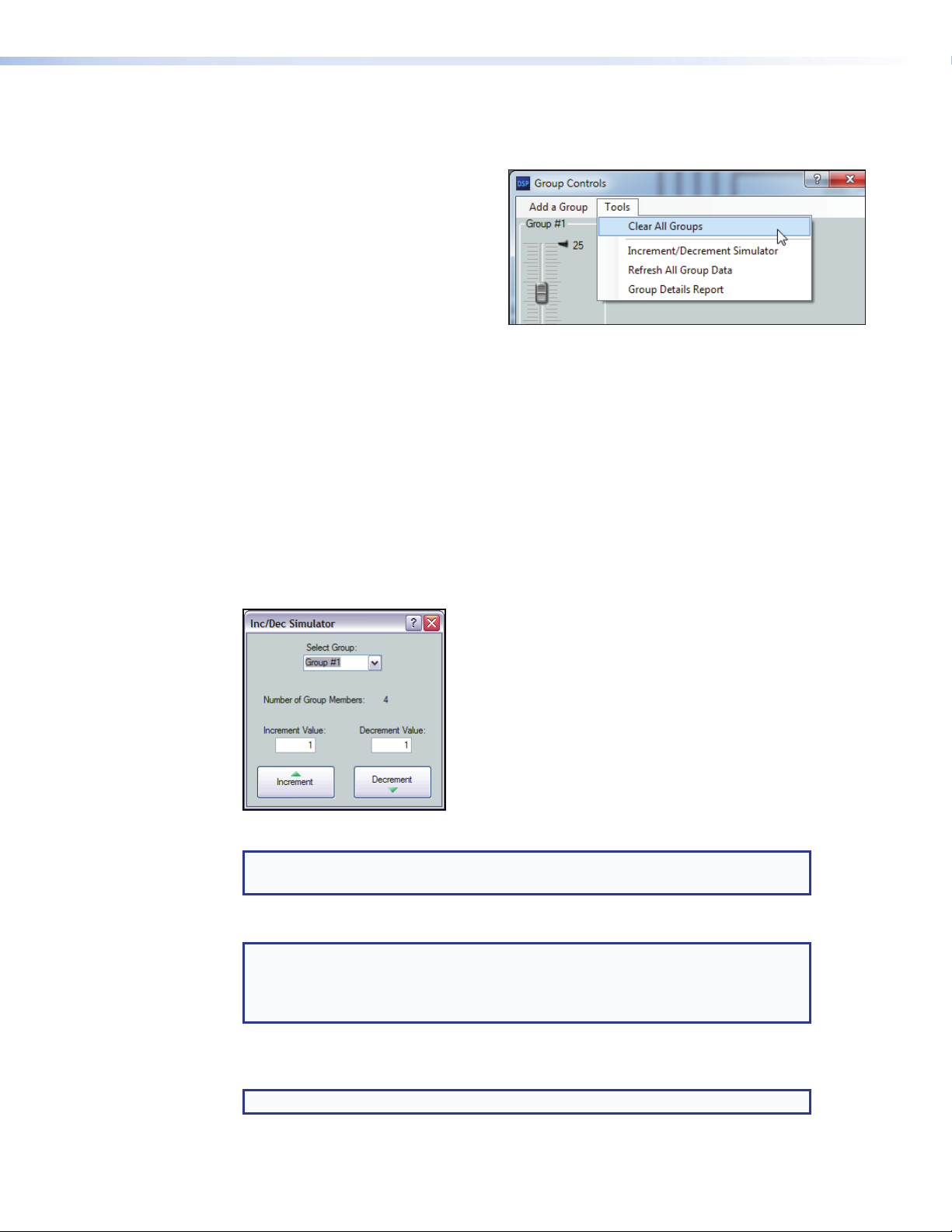
Tools
The Tools menu (see right) contains these selections:
• Clear All Groups — clears all
group members and group master
parameters. Soft limits are also
cleared.
• Increment/Decrement
Simulator — allows the user to
test increment/decrement values (see
below for more information)
• Refresh All Group Data —
Updates group members and group master parameters.
• Group Details Report — generates a report, listing all group masters and membership
(see Group Details Report on page87).
Increment/Decrement Simulator
The Increment/Decrement Simulator provides a control for increment and decrement, with the
ability to set increment and decrement values. The control is temporary, since the value is not
remembered in the device.
To use the Increment/Decrement Simulator:
1. Select Tools > Increment/Decrement Simulator.
2. Select the group to be controlled from the Select Group drop-down list. The following
dialog box opens:
Figure 55. Increment/Decrement Simulator Dialog Box
NOTE: The Number of Group Members: readout indicates the number of
controls affected.
3. Enter an increment value and a decrement value. The default value is 1.
NOTE: The size of the increment can be changed by typing a value in the
Increment Value or Decrement Value field. Values can be as large as
the maximum range of the control or as fine as 0.1dB. For groups controlling
mute, 1 is the only valid value.
4. Click Increment and Decrement as needed. The group master control increases or
decreases by the set value to the top or bottom of its soft limit range.
NOTE: When set, soft limits cannot be exceeded.
DMP128 • Software Control 86
Page 93
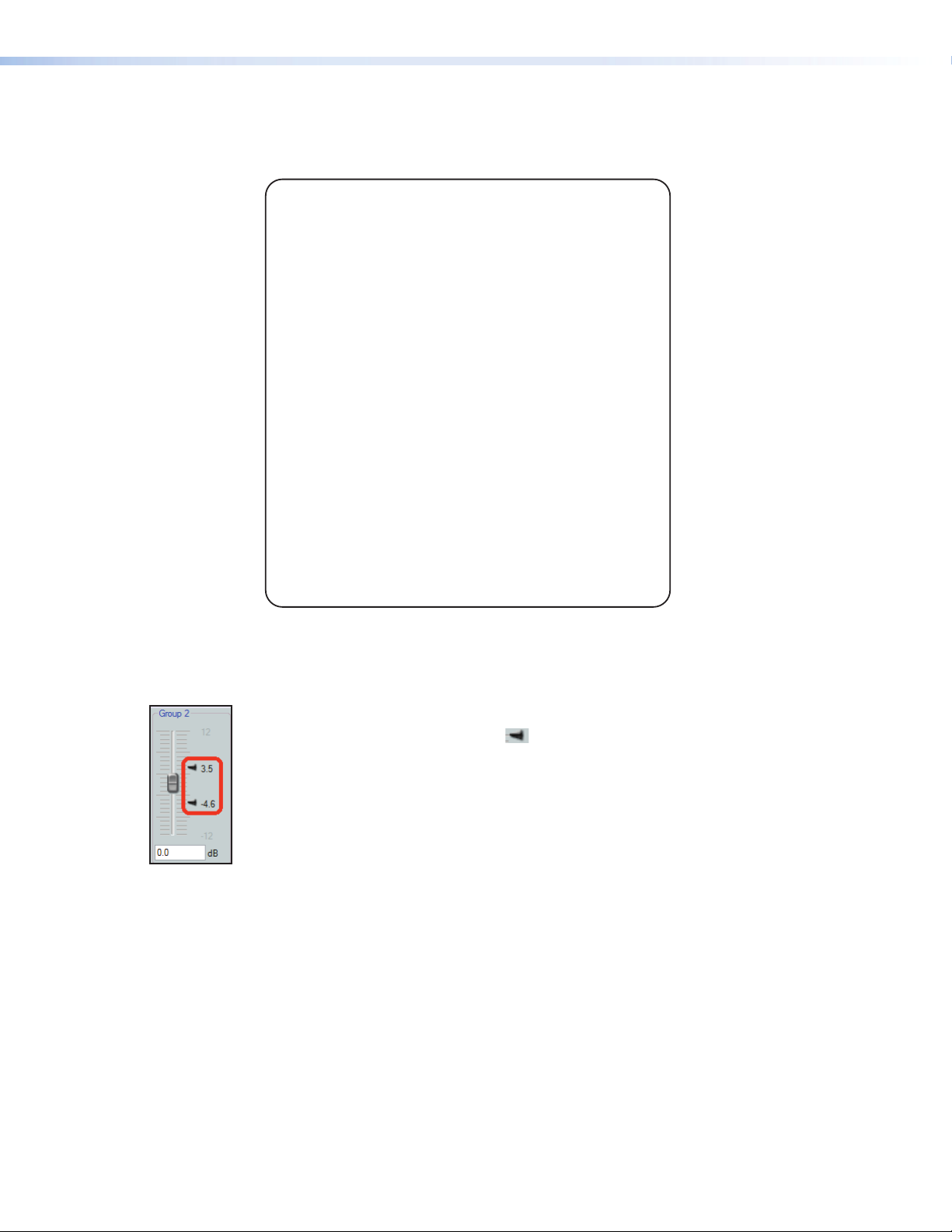
Group Details Report
Select Tools > Group Details Report to create a text file that details all created
groups (see figure 56).
GROUP DETAILS REPORT
Group #1
Processor Type: Output Volume
Current Mute status: Unmuted
Current Group Members:
Main Amp (Output#1) Left Channel
Stage Mixer (Output#2) Right Channel
House Video (Output#3) Left Channel
Prgm Record (Output#4) Right Channel
Group #2
Processor Type: Pre-mixer Trim
Current Gain value: 2 dB
Current Group Members:
Mic #1 (Input#1)
Mic #2 (Input#2)
Mic #3 (Input#3)
Mic #4 (Input#4)
Mic #5 (Input#5)
Mic #6 (Input#6)
Figure 56. Sample Group Details Report
Soft Limits
Each gain type control provides upper and lower soft limits used to limit the range of
the group master control. Soft limits ( ), shown at left, prevent group controls from
exceeding an upper limit or going below a lower limit. They are easily adjustable and
provide the ability to set a ceiling and floor for the group. When a group master is created,
the soft limits default to the hard limits (maximum and minimum) of that group of controls.
Soft limits can be defined using the mouse by clicking on, then dragging the
Soft Limit icon. The resolution is 0.1dB.
For more precise setting use the keyboard as follows:
Click within the group master fader to bring focus, then use the following key
combinations:
To move the upper limit:
• <Shift + Up/down arrow> moves in 0.1dB increments.
• <Shift + Page Up/Page Down> moves in 10dB increments.
• <Shift + Home> moves limit to upper default. <Shift + End> moves limit to the current
fader position.
To move the lower limit:
• <Ctrl + Up/down arrow> moves in 0.1dB increments.
• <Ctrl + Page Up/Page Down> moves in 10dB increments.
• <Ctrl + Home> moves limit to the current fader position. <Ctrl + End> moves limit to
lower default.
DMP128 • Software Control 87
Page 94

DigitalI/OPorts
The DMP128 provides twenty digital I/O ports that can trigger external events from
DMP128 actions, or allow external events to trigger DMP128 actions. DSPConfigurator
provides pre-configured scripts with a fixed set of common trigger or event combinations.
When selected, the script is compiled and placed onto the File Management system
of the device. For more advanced or custom scripts, contact an Extron Electronics
Applications Engineer.
When there are no scripts active, the digital I/O ports default to DI (digital input) and
inactive (‘Logic Hi’ ≈ +5VDC). The DI detects a Logic Hi as +5 VDC and LogicLow
(active) as less than +1 VDC.
A DO (digital output) sends a Logic Lo as less than +1 VDC and a Logic Hi as +5VDC.
For every script that involves a DO, two versions are available to provide either a Logic Hi
or a Logic Lo response to any action. The alternate script is designated as “ReverseDO”.
To build a script and place it into the DMP128 File Management system:
1. From the main menu, click Tools>Configure Digital I/O>Build Digital
I/O Configuration.
A dialog box opens with a list of pre-configured scripts.
2. Select a script from the Select a Digital I/O Configuration section. The
Event Description panel describes the script and how the digital I/O ports act
while the script is running. Highlight the desired script, then click OK.
A dialog box opens, verifying the file has successfully uploaded to the device.
NOTE: When performing this procedure in Emulate mode, the connection
dialog appears between step 3 and step 4. The DSP Configurator connects
and then disconnects during the procedure, returning to Emulate mode when
completed.
DMP128 • Software Control 88
Page 95

Reinitialize Digital I/O
Should the script stop running for any reason, select
Tools > Configure DigitalI/O > Reinitialize Digital I/O.
This option is only available in live mode.
To remove a digital I/O script from the DMP128:
Only one digital I/O configuration can be active at a time. If the I/O activity requires
modification, remove the current configuration by:
1. From the main menu, select Tools>Configure Digital I/O > Remove
Digital I/O Configuration from the Device and click OK.
2. If the DSP Configurator is connected to a device, the I/O configuration is removed. If it
is not connected, a connection dialog box appears.
3. Make certain the connection information is correct, then click OK. The I/O
configuration script is removed and a confirmation dialog box appears.
Emulate Mode and Live Mode
DSP Configurator has two operational modes, Live and Emulate. In live mode, the
program has established a connection and is synced with the DMP128. Changes affect
the device in real-time and changes in the current state of the device are reflected in
DSPConfigurator. In contrast, emulate mode allows the user to work offline, creating or
editing configurations that do not immediately affect DMP128 operation.
DSP Configurator always starts in Emulate mode. In Emulate mode, all functions of
DSPConfigurator are available without connecting to the DMP128. The user can build
a configuration from the blank screen, or open an existing file that contains the last
configuration displayed plus saved presets. Settings and adjustments are saved to
a configuration file on the PC. When the saved file is opened in DSPConfigurator, all
settings are restored as the current configuration (emulated if in Emulate mode or live if in
Live mode).
Live mode can be entered at any time after program launch, either with a blank
configuration, after creating a configuration, or after loading a previously saved
configuration file.
In emulate mode, the current state is titled Current Emulation. In live mode, the current
state is titled, Current State.
Synchronizing: Pull from or Push to the Device
When switching to live mode, either:
• Pull data from the device and update the program configuration. This
option downloads device settings from the DMP128 and synchronizes it with
DSPConfigurator overwriting the current DSPConfigurator settings, or
• Push data from DSPConfigurator to the device, overwriting settings in the DMP128.
Live mode is also used to tailor audio settings in real time while listening to the audio
output.
DMP128 • Software Control 89
Page 96

Selecting Live Mode and Pushing or Pulling Data
To switch from Emulate to Live mode:
1. Select the desired connection to the DMP128 and make the proper connections.
NOTE: Extron recommends connection via the Ethernet LAN port when using
DSPConfigurator.
2. Click Live (see figure 57, b). The communication type selection dialog opens.
2
3
4a
or
4b
4c
3
5a
5b
5c
or
3
Extron USB device
6a
6b
Figure 57. Selecting Live Mode
3. To select the connection method, click:
• TCP/IP (for connection of the LAN port (preferred) — proceed to step 4
• RS-232 (for connection of the rear panel RS-232 port — proceed to step 5
• USB (for connection of the front panel configuration port — proceed to step6
4. If TCP/IP is selected in step 3:
a. Observe the IP address field in the IP connection dialog box. The field displays
the last IP address entered.
• If the IP Address field is correct, proceed to step 4b
• If the address is not correct, either click in the IP Address field and
enter the correct IP address or click ( ) to open a drop-down list and select
from among recently used addresses. Proceed to step 4b
NOTE: If the local system administrators have not changed the value,
the factory-specified default, 192.168.254.254, is the correct value
for this field.
b. If the device is password protected, click in the Password field and enter the
appropriate administrator password
c. Click OK
The Synchronize with Device dialog box (see figure 58 on page 92) opens.
Proceed to step 7.
DMP128 • Software Control 90
Page 97

5. If RS-232 is selected in step 3:
a. Click the Com Port drop-down list and select the port connected to the rear
panel RS-232 port.
b. Check the baud rate displayed in the port selection dialog box. If the baud rate
does not match the device rate, click the Baud Rate drop-down list and select
the desired baud rate. The default is 38400.
c. Click OK.
The Synchronize with Device dialog box (figure 58 on next page) opens.
Proceed to step 7.
6. If USB is selected in step3:
a. Click the USB Device drop-down list and select DMP128 (or Extron USB
device, if DMP128 is not available),
b. Click OK.
The Synchronize with Device dialog box (see figure 58 on next page) opens.
Proceed to step 7.
DMP128 • Software Control 91
Page 98
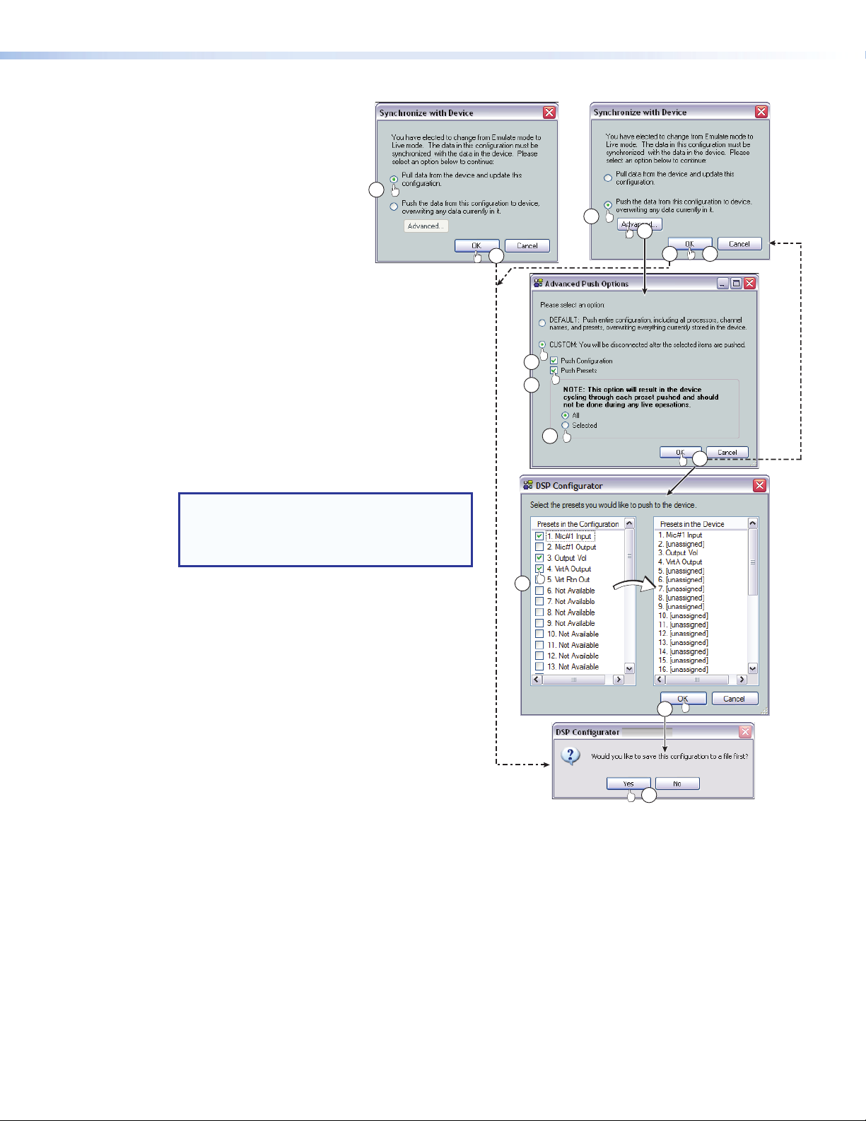
7. Click either:
a. Pull to configure DSP
Configurator to match the
device — proceed to step9
-or-
7a
b. Push to configure the device
to match DSPConfigurator
— proceed to step8
8. To push all of the gain and
processor block adjustments
(configuration), and all presets to the DMP128,
proceed to step9.
To tailor the push (push only the configuration,
only the presets, or the configuration and selected
presets), click Advanced and proceed to step 8a.
a. Select the Custom radio button.
b. Select the desired checkbox or checkboxes;
Push Configuration and/or Push Presets.
If Push Configuration is the only box
checked, click OK and proceed to step9.
NOTE: Push Configuration includes
all mix-point, gain and processor block
settings. It does not include partial
presets.
-or-
7b
8
8d
9
8a
8b
8c
9
8d
c. If Push Presets was selected in step 8b, click
8e
All to select all presets or Selected to choose
specific presets.
• If Selected is clicked, click OK and proceed
to step 8d.
• If All is clicked (equivalent to a standard
push), click OK and proceed to step 9.
8f
d. If Selected is clicked in step 8c, the
Synchronize with Device dialog box (7b)
reopens. Click OK. The presets dialog box opens.
e. Select the desired partial presets to push by
clicking the appropriate checkbox or checkboxes.
f. Click OK. — Proceed to step 10.
Figure 58. Selecting Live Mode (Continued)
10
9. Click OK. The DSP Configurator program is connected live to the device and the processors and
presets are pushed or pulled as selected, completing the selection of Live mode.
10. If changes are made to the DSP parameters (including mix-point, gain or processor blocks) since the
last file save, DSP Configurator prompts to save the file. Click Yes or No.
If a password is required and not entered or if an incorrect password isentered, the program prompts
for the password.
The configuration and presets are uploaded to the DMP128.
DMP128 • Software Control 92
Page 99
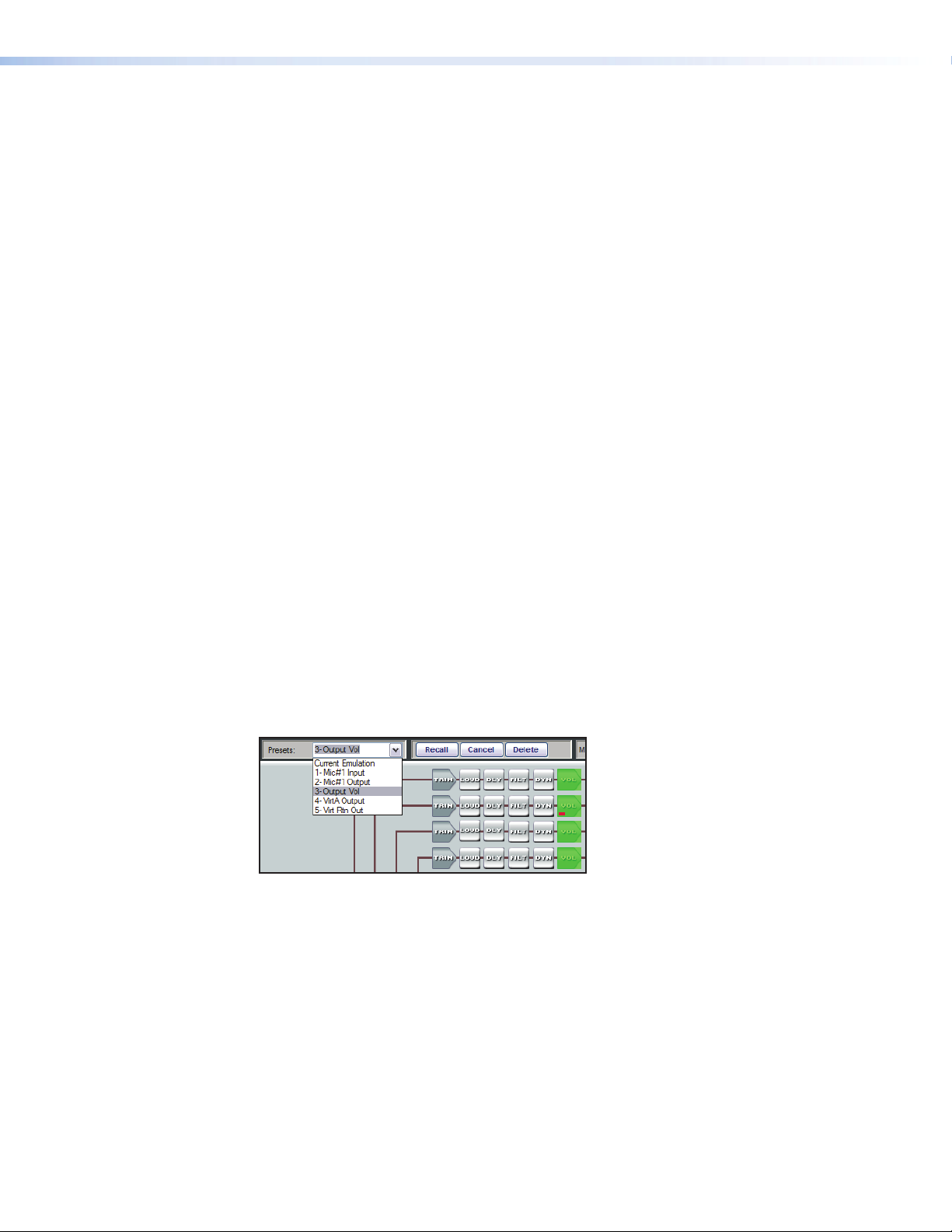
Presets
Presets recall a group of frequently used settings. Presets created by DSPConfigurator
can contain all elements (gain blocks, processor blocks, and mix-points) or a portion of
the elements available within the program. In Emulate mode, up to 32 partial presets
can be created, then uploaded as a set and stored to the device or stored to disk as a
configuration file. In Live mode, presets can be created one at a time from the current
state. They can be saved to a chosen preset number in the device, with the option to
name or rename, or save to disk.
When recalled, a preset overwrites only elements contained in the preset. Presets are
useful when settings for a particular room or only certain elements of a configuration need
to be changed regularly.
Presets can be created in Live or Emulate modes. In Emulate mode, presets are
created, saved to a file, then pushed to the DMP128 when connecting in Live mode.
When a pull data synchronization method is performed, preset data remains in the
DMP128, with only the list of preset names pulled from the device. Presets in this state
are marked with an asterisk until that preset is recalled (which pulls the preset data from
the device), or until a backup is performed (see Backup on page26). Presets pulled
from the device cannot be saved to disk until they have been recalled, at which time the
preset data is pulled into the DSP Configurator. Presets with no asterisk can be saved to
disk.
Saved presets can be recalled via the DSP Configurator, or a control system sending an
SIS preset recall command. Presets may also be saved and recalled via the embedded
web page. Presets saved via the web page contain input gain, output volume, and the
output mix-point settings.
Previewing and Recalling a Preset
A preset can be previewed in either Live or Emulate mode by selecting the preset from
the preset drop-down list.
The program indicates a view-only preset configuration by displaying each preset element
with a translucent green mask over the block.
Figure 59. Preset Preview
Behavior for previewing and applying presets is as follows:
• Live Mode – After selecting a preset, DSP Configurator displays the preset elements
that are affected by a preset recall with a translucent mask over the element, and
leaves all other DSP Configurator elements unaltered. Elements without a translucent
mask represent elements in the current state that are unaffected by a preset recall.
Real-time changes to the current state are not reflected while previewing a preset,
and the user cannot alter those elements. To apply the preset, click Recall. The
preset reverts to Current State.
• Emulate Mode – After selecting a preset from the list, DSP Configurator displays the
elements affected by a preset recall with a green translucent mask, leaving all other
elements (which represent the current emulation) unaltered. Click Recall to apply
the viewed preset to the current emulation. The preset number reverts to Current
Emulation.
DMP128 • Software Control 93
Page 100

Building a Preset
Only elements of the preset highlighted (given focus) are saved as a preset. <Ctrl+A>
highlights all elements within DSP Configurator.
To build a preset, highlight the desired DSP Configurator elements (gain/processor blocks,
mix-points) using standard Windows keyboard and mouse actions as follows:
1. Click on the desired block to select a single block,
2. <Ctrl + click> to select multiple blocks that are not adjacent,
3. <Shift/hold + click> on the first block and click on the last block in either a vertical
column or horizontal row to select multiple blocks, and
4. Click and drag a selection rectangle to select multiple adjacent blocks in either the
vertical or horizontal direction.
5. Select Tools > Presets > Mark All Items or press <Ctrl + A>. This marks all
elements within DSP Configurator, which saves a “full” preset,
6. To save the selection see Save Preset below.
Save Preset
A preset is saved in either Emulate mode or Live mode.
Saving a preset in Emulate mode stores that preset in the currently open file. The
DSPConfigurator file is saved to disk using File menu > Save (recommended), and
pushed to the device after a connection is established. This differs from Live mode
where the created preset is saved in real-time to the device and becomes part of the
configuration file.
To save a preset:
1. Highlight the desired preset block(s) by using click, <Ctrl + click>, <shift+click> or
drag around the desired blocks.
2. Select Tools > Presets > Save Preset.
DMP128 • Software Control 94
 Loading...