

Page 1
Installation Guide
Extron Electronics, USA
1230 South Lewis Street
Anaheim, CA 92805
800.633.9876 714.491.1500
FAX 714.491.1517
Extron Electronics, Europe
Beeldschermweg 6C
3821 AH Amersfoort, The Netherlands
+800.3987.6673 +31.33.453.4040
FAX +31.33.453.4050
Extron Electronics, Asia
135 Joo Seng Rd. #04-01
PM Industrial Bldg., Singapore 368363
+800.7339.8766 +65.6383.4400
FAX +65.6383.4664
Extron Electronics, Japan
Kyodo Building, 16 Ichibancho
Chiyoda-ku, Tokyo 102-0082
Japan
+81.3.3511.7655 FAX +81.3.3511.7656
www.extron.com
© 2007 Extron Electronics. All rights reserved.
CVC 200
Component Video and HDTV to RGB Converter
68-437-01 Rev. D
08 07
Page 2
O
U
T
P
U
T
I
N
P
U
T
F
O
R
M
A
T
Extron
CVC 200
Video Converter
HDTV
Set Top Box
Large Screen
Rear Projector
LCD Projector
Video Monitor
DVD
or
or
(2) 4-40 x 3/16" Screws
Use 2 mounting holes on
opposite corners.
False front panel
uses 2 front holes.
#10-32 Screw
w/ Nylon Captive
Cap Washer
C
V
C
2
0
0
Introduction
Mounting
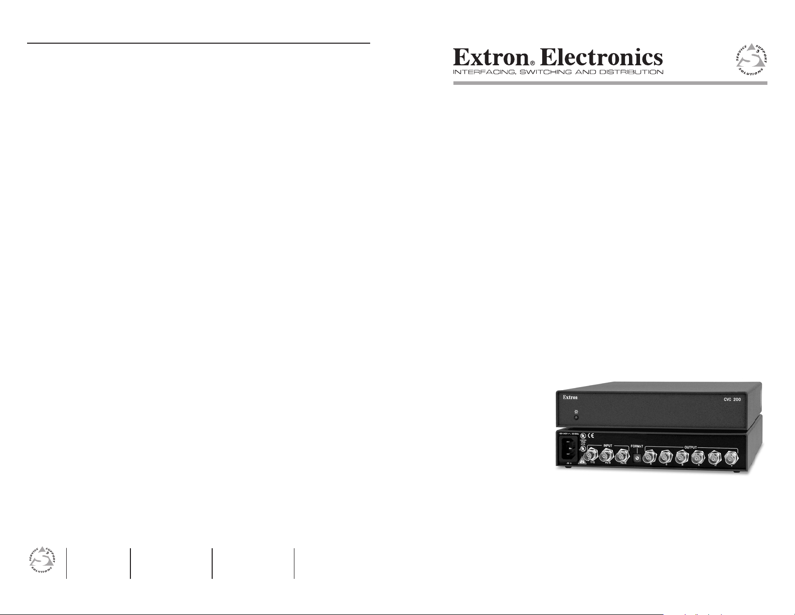
The CVC 200 Component Video Converter converts all SMPTE
standard component video formats to RGBS or RGBHV video. The
CVC 200 can also strip sync-on-green (SOG) from RGsB video.
The converter outputs converted RGBS or RGBHV video on BNC
connectors. Figure 1 shows a typical CVC 200 application.
Figure 1 — Typical CVC 200 application
The component video input formats include DVD, Betacam® video, and
HDTV component video. The RGsB video input can be computer video
or NTSC/PAL video.
3. Mechanical loading — Mount the equipment in the rack so that
a hazardous condition is not achieved due to uneven mechanical
loading.
4. Circuit overloading — Connect the equipment to the supply
circuit and consider the effect that circuit overloading might
have on overcurrent protection and supply wiring. Appropriate
consideration of equipment nameplate ratings should be used
when addressing this concern.
5. Reliable earthing (grounding) — Maintain reliable grounding
of rack-mounted equipment. Pay particular attention to supply
connections other than direct connections to the branch circuit
(e.g. use of power strips).
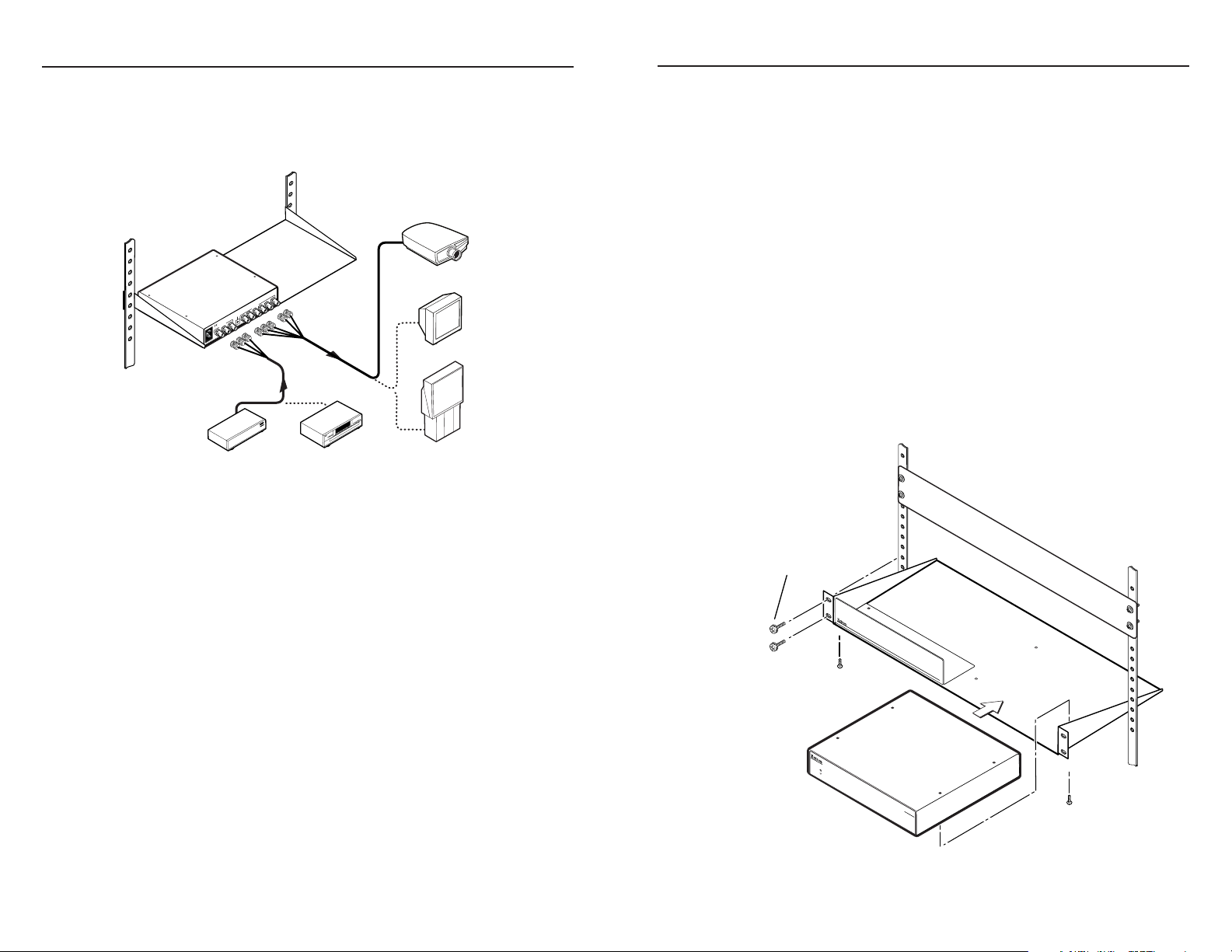
Mounting instructions
Rack mount the CVC 200 as follows:
1. Remove the feet from the CVC, if they were previously installed.
2. Mount the CVC 200 on the rack shelf, using two 4-40 x 3/16”
screws in opposite corners (under the shelf) to secure the CVC to
the shelf (figure 2).
Mounting
1
The CVC 200 can be rack mounted using one side of a 1U Universal
Rack Shelf (part #60-190-01) or 1U Basic Rack Shelf (part #60-604-01).
UL requirements
The following Underwriters Laboratories (UL) requirements pertain to
the installation of the CVC into a rack.
1. Elevated operating ambient temperature — If the equipment
installed in a closed or multi-unit rack assembly, the operating
ambient temperature of the rack environment may be greater
than room ambient temperature. Therefore, install the CVC in an
environment compatible with the maximum ambient temperature
(Tma = +122 °F, +50 °C) specified by Extron.
2. Reduced air flow — Install the equipment in a rack so that the
amount of air flow required for safe operation of the equipment is
not compromised.
CVC 200 • Installation
Figure 2 — Rack mounting the CVC 200
CVC 200 • Installation
2
Page 3

Cable Connection and Rate Selection
OUTPUT
R
G B
S
H V
PR/R
PB/B
Y/G
INPUT FORMAT
LIST ED
1T23
I.T. E.
C
.35A
100-240V 50-60Hz
2 4
1
3
PR/R
PB/B
Y/G
PR/R
PB/B
Y/G
Y, PB, P
R
RGsB
(SOG)
video
Y, B-Y, R-Y
video
video
PR/R
PB/B
Y/G
(R-Y)
(B-Y)
Position
0
1
2
3
4
5
6
7
8
9
A
B-F
Input
format(s)
Not used
Y, Pb, Pr
Y, Pb, Pr
Y, Pb, Pr
Not used
RGsB
RGsB
Y, Pb, Pr
Y, Pb, Pr
Y, Pb, Pr
Y, Pb, Pr
Not used
Standard or rate
NTSC/PAL
HDTV (480p, 576p, 720p, 1035i, 1080i)
Betacam
NTSC/PAL
Computer rates
NTSC/PAL
HDTV (720p)
HDTV (1080i)
HDTV (1080p)
Format
switch
R
V
G B
S
H
R
V
G B
S
H
RGBHV
video
RGBS
video
Cable Connection and Rate Selection (Cont’d)
Cable Connection and Rate Selection
See figure 3 to identify the rear panel connections and Format rotary
switch
Figure 3 — CVC 200 rear panel features
Power connector — Plug a standard IEC power cord into this
a
connector to connect the CVC 200 to a 100 to 240VAC, 50 Hz or
60 Hz power source.
Input connectors — Connect a component video input device
b
(HDTV, W-VHS [Y, Pr, Pb], SMPTE [Y, R-Y, B-Y]), Betacam®
[Y, R-Y, B-Y]) or an RGsB input device to these female BNC
connectors. Use high-resolution cable, such as Extron’s BNC4 mini HR, RG59/HR, or RG6/SHR cable. Connect the input
device as shown in figure 4.
Format rotary switch — Use an Extron Tweeker or other small
c
screwdriver to set the Format rotary switch to match the video
input format. The table below shows the switch settings and their
assigned input video formats.
Output connectors — Connect an RGBHV or RGBS display to
d
these female BNC connectors. Use high-resolution cable, such
as Extron’s BNC-4 or BNC-5 mini HR, RG59/HR, or RG6/SHR
cable. Connect the display as shown in figure 5.
Figure 4 — Input connections
Figure 5 — Output connections
3
CVC 200 • Cable Connection and Rate Selection
CVC 200 • Rate Selection
4
Page 4

Specifications
Specifications (Cont’d)
Specifications
Video
Gain ................................................ Unity
Bandwidth ..................................... 55 MHz (-3 dB)
Video input
Number/signal type ..................... 1 component video [HDTV, W-VHS (Y, Pr, Pb),
SMPTE (Y, R-Y, B-Y), and Betacam®
(Y, R-Y, B-Y)] or RGsB
Connectors .................................... 3 BNC female
Nominal level ................................ 1V p-p for Y of component video
0.3V p-p for R-Y and B-Y of component video
0.7V p-p for PB PR
Minimum/maximum levels ........ Y: 0.5 V to 1.5 Vp-p with no offset at unity gain
PB PR: 0.4 V to 1.0 Vp-p with no offset at unity
gain
Impedance ..................................... 75 ohms
Horizontal frequency .................... 15.75 kHz to 100 kHz according to selected mode
Vertical frequency .......................... 60 Hz
Return loss ..................................... <-25 dB @ 5 MHz
DC offset (max. allowable)........... ±2 V (maximum)
Video output
Number/signal type ..................... 1 RGBHV, RGBS
Connectors .................................... 6 BNC female
Nominal level ................................ 0.7 Vp-p for RGB
Minimum/maximum levels ........ RGB: 0.4 V to 1.0 Vp-p
Impedance ..................................... 75 ohms
Return loss ..................................... <-30 dB @ 5 MHz
DC offset ........................................ 0.1 V with input at 0 offset
General
Power ............................................. 100 VAC to 240 VAC, 50/60 Hz, 12 watts,
internal, autoswitchable
Temperature/humidity ................ Storage -40° to +158°F (-40° to +70°C) / 10% to
90%, noncondensing
Operating +32° to +122°F (0° to +50°C) / 10% to
90%, noncondensing
Rack mount .................................... Yes, with optional rack shelf,
part #60-190-01 or #60-604-01
Enclosure type .............................. Metal
Enclosure dimensions .................. 1.6” H x 8.75” W x 9.4” D
(1U high, half rack wide)
4.1 cm H x 22.2 cm W x 23.9 cm D
(Depth excludes connectors.)
Product weight .............................. 2.8 lbs (1.3 kg)
Shipping weight ........................... 5 lbs (3 kg)
Vibration ........................................ ISTA 1A in carton
(International Safe Transit Association)
Listings............................................ UL, CUL
Compliances ................................... CE
MTBF ............................................... 30,000 hours
Warranty ........................................ 3 years parts and labor
N
N
All nominal levels are at ±10%.
Specifications are subject to change without notice.
5
CVC 200 • Specifications
CVC 200 • Specifications
6
 Loading...