

Extron electronics CrossPoint 450 Plus 84 HV, CrossPoint 450 Plus 88 HVA, CrossPoint 450 Plus 128 HV, CrossPoint 450 Plus 128 HVA, CrossPoint 450 Plus 124 HVA User Manual
...Page 1

CrossPoint 450 Plus Series
im Vertrieb von
CAMBOARD Electronics
www.camboard.de
Tel. 07131 911201
Fax 07131 911203
ce-info@camboard.de
MAV Plus Series
Matrix Switchers
68-521-02 Rev. B
12 04
Page 2

Precautions
im Vertrieb von
CAMBOARD Electronics
www.camboard.de
Tel. 07131 911201
Fax 07131 911203
ce-info@camboard.de
Safety Instructions • English
This symbol is intended to alert the user of important operating and maintenance
(servicing) instructions in the literature provided with the equipment.
This symbol is intended to alert the user of the presence of uninsulated dangerous
voltage within the product's enclosure that may present a risk of electric shock.
Caution
Read Instructions • Read and understand all safety and operating instructions before using the
equipment.
Retain Instructions • The safety instructions should be kept for future reference.
Follow Warnings • Follow all warnings and instructions marked on the equipment or in the user
information.
Avoid Attachments • Do not use tools or attachments that are not recommended by the equipment
manufacturer because they may be hazardous.
Consignes de Sécurité • Français
Ce symbole sert à avertir l’utilisateur que la documentation fournie avec le matériel
contient des instructions importantes concernant l’exploitation et la maintenance
(réparation).
Ce symbole sert à avertir l’utilisateur de la présence dans le boîtier de l’appareil de
tensions dangereuses non isolées posant des risques d’électrocution.
Attention
Lire les instructions• Prendre connaissance de toutes les consignes de sécurité et d’exploitation avant
d’utiliser le matériel.
Conserver les instructions• Ranger les consignes de sécurité afin de pouvoir les consulter à l’avenir.
Respecter les avertissements • Observer tous les avertissements et consignes marqués sur le matériel ou
présentés dans la documentation utilisateur.
Eviter les pièces de fixation • Ne pas utiliser de pièces de fixation ni d’outils non recommandés par le
fabricant du matériel car cela risquerait de poser certains dangers.
Sicherheitsanleitungen • Deutsch
Dieses Symbol soll dem Benutzer in der im Lieferumfang enthaltenen
Dokumentation besonders wichtige Hinweise zur Bedienung und Wartung
(Instandhaltung) geben.
Dieses Symbol soll den Benutzer darauf aufmerksam machen, daß im Inneren des
Gehäuses dieses Produktes gefährliche Spannungen, die nicht isoliert sind und
die einen elektrischen Schock verursachen können, herrschen.
Achtung
Lesen der Anleitungen • Bevor Sie das Gerät zum ersten Mal verwenden, sollten Sie alle Sicherheits-und
Bedienungsanleitungen genau durchlesen und verstehen.
Aufbewahren der Anleitungen • Die Hinweise zur elektrischen Sicherheit des Produktes sollten Sie
aufbewahren, damit Sie im Bedarfsfall darauf zurückgreifen können.
Befolgen der Warnhinweise • Befolgen Sie alle Warnhinweise und Anleitungen auf dem Gerät oder in
der Benutzerdokumentation.
Keine Zusatzgeräte • Verwenden Sie keine Werkzeuge oder Zusatzgeräte, die nicht ausdrücklich vom
Hersteller empfohlen wurden, da diese eine Gefahrenquelle darstellen können.
Warning
Power sources • This equipment should be operated only from the power source indicated on the
product. This equipment is intended to be used with a main power system with a grounded
(neutral) conductor. The third (grounding) pin is a safety feature, do not attempt to bypass or
disable it.
Power disconnection • To remove power from the equipment safely, remove all power cords from
the rear of the equipment, or the desktop power module (if detachable), or from the power
source receptacle (wall plug).
Power cord protection • Power cords should be routed so that they are not likely to be stepped on or
pinched by items placed upon or against them.
Servicing • Refer all servicing to qualified service personnel. There are no user-serviceable parts
inside. To prevent the risk of shock, do not attempt to service this equipment yourself because
opening or removing covers may expose you to dangerous voltage or other hazards.
Slots and openings • If the equipment has slots or holes in the enclosure, these are provided to
prevent overheating of sensitive components inside. These openings must never be blocked by
other objects.
Lithium battery • There is a danger of explosion if battery is incorrectly replaced. Replace it only
with the same or equivalent type recommended by the manufacturer. Dispose of used batteries
according to the manufacturer's instructions.
Avertissement
Alimentations• Ne faire fonctionner ce matériel qu’avec la source d’alimentation indiquée sur
l’appareil. Ce matériel doit être utilisé avec une alimentation principale comportant un fil de
terre (neutre). Le troisième contact (de mise à la terre) constitue un dispositif de sécurité :
n’essayez pas de la contourner ni de la désactiver.
Déconnexion de l’alimentation• Pour mettre le matériel hors tension sans danger, déconnectez tous
les cordons d’alimentation de l’arrière de l’appareil ou du module d’alimentation de bureau (s’il
est amovible) ou encore de la prise secteur.
Protection du cordon d’alimentation • Acheminer les cordons d’alimentation de manière à ce que
personne ne risque de marcher dessus et à ce qu’ils ne soient pas écrasés ou pincés par des
objets.
Réparation-maintenance • Faire exécuter toutes les interventions de réparation-maintenance par un
technicien qualifié. Aucun des éléments internes ne peut être réparé par l’utilisateur. Afin
d’éviter tout danger d’électrocution, l’utilisateur ne doit pas essayer de procéder lui-même à ces
opérations car l’ouverture ou le retrait des couvercles risquent de l’exposer à de hautes tensions
et autres dangers.
Fentes et orifices • Si le boîtier de l’appareil comporte des fentes ou des orifices, ceux-ci servent à
empêcher les composants internes sensibles de surchauffer. Ces ouvertures ne doivent jamais
être bloquées par des objets.
Lithium Batterie • Il a danger d'explosion s'll y a remplacment incorrect de la batterie. Remplacer
uniquement avec une batterie du meme type ou d'un ype equivalent recommande par le
constructeur. Mettre au reut les batteries usagees conformement aux instructions du fabricant.
Vorsicht
Stromquellen • Dieses Gerät sollte nur über die auf dem Produkt angegebene Stromquelle betrieben
werden. Dieses Gerät wurde für eine Verwendung mit einer Hauptstromleitung mit einem
geerdeten (neutralen) Leiter konzipiert. Der dritte Kontakt ist für einen Erdanschluß, und stellt
eine Sicherheitsfunktion dar. Diese sollte nicht umgangen oder außer Betrieb gesetzt werden.
Stromunterbrechung • Um das Gerät auf sichere Weise vom Netz zu trennen, sollten Sie alle
Netzkabel aus der Rückseite des Gerätes, aus der externen Stomversorgung (falls dies möglich
ist) oder aus der Wandsteckdose ziehen.
Schutz des Netzkabels • Netzkabel sollten stets so verlegt werden, daß sie nicht im Weg liegen und
niemand darauf treten kann oder Objekte darauf- oder unmittelbar dagegengestellt werden
können.
Wartung • Alle Wartungsmaßnahmen sollten nur von qualifiziertem Servicepersonal durchgeführt
werden. Die internen Komponenten des Gerätes sind wartungsfrei. Zur Vermeidung eines
elektrischen Schocks versuchen Sie in keinem Fall, dieses Gerät selbst öffnen, da beim Entfernen
der Abdeckungen die Gefahr eines elektrischen Schlags und/oder andere Gefahren bestehen.
Schlitze und Öffnungen • Wenn das Gerät Schlitze oder Löcher im Gehäuse aufweist, dienen diese
zur Vermeidung einer Überhitzung der empfindlichen Teile im Inneren. Diese Öffnungen dürfen
niemals von anderen Objekten blockiert werden.
Litium-Batterie • Explosionsgefahr, falls die Batterie nicht richtig ersetzt wird. Ersetzen Sie
verbrauchte Batterien nur durch den gleichen oder einen vergleichbaren Batterietyp, der auch
vom Hersteller empfohlen wird. Entsorgen Sie verbrauchte Batterien bitte gemäß den
Herstelleranweisungen.
Instrucciones de seguridad • Español
Este símbolo se utiliza para advertir al usuario sobre instrucciones importantes de
operación y mantenimiento (o cambio de partes) que se desean destacar en el
contenido de la documentación suministrada con los equipos.
Este símbolo se utiliza para advertir al usuario sobre la presencia de elementos con
voltaje peligroso sin protección aislante, que puedan encontrarse dentro de la caja
o alojamiento del producto, y que puedan representar riesgo de electrocución.
Precaucion
Leer las instrucciones • Leer y analizar todas las instrucciones de operación y seguridad, antes de usar
el equipo.
Conservar las instrucciones • Conservar las instrucciones de seguridad para futura consulta.
Obedecer las advertencias • Todas las advertencias e instrucciones marcadas en el equipo o en la
documentación del usuario, deben ser obedecidas.
Evitar el uso de accesorios • No usar herramientas o accesorios que no sean especificamente
recomendados por el fabricante, ya que podrian implicar riesgos.
Advertencia
Alimentación eléctrica • Este equipo debe conectarse únicamente a la fuente/tipo de alimentación
eléctrica indicada en el mismo. La alimentación eléctrica de este equipo debe provenir de un
sistema de distribución general con conductor neutro a tierra. La tercera pata (puesta a tierra) es
una medida de seguridad, no puentearia ni eliminaria.
Desconexión de alimentación eléctrica • Para desconectar con seguridad la acometida de
alimentación eléctrica al equipo, desenchufar todos los cables de alimentación en el panel trasero
del equipo, o desenchufar el módulo de alimentación (si fuera independiente), o desenchufar el
cable del receptáculo de la pared.
Protección del cables de alimentación • Los cables de alimentación eléctrica se deben instalar en
lugares donde no sean pisados ni apretados por objetos que se puedan apoyar sobre ellos.
Reparaciones/mantenimiento • Solicitar siempre los servicios técnicos de personal calificado. En el
interior no hay partes a las que el usuario deba acceder. Para evitar riesgo de electrocución, no
intentar personalmente la reparación/mantenimiento de este equipo, ya que al abrir o extraer las
tapas puede quedar expuesto a voltajes peligrosos u otros riesgos.
Ranuras y aberturas • Si el equipo posee ranuras o orificios en su caja/alojamiento, es para evitar el
sobrecalientamiento de componentes internos sensibles. Estas aberturas nunca se deben obstruir
con otros objetos.
Batería de litio • Existe riesgo de explosión si esta batería se coloca en la posición incorrecta. Cambiar
esta batería únicamente con el mismo tipo (o su equivalente) recomendado por el fabricante.
Desachar las baterías usadas siguiendo las instrucciones del fabricante.
Page 3

Quick Start — CrossPoint 450 Plus
im Vertrieb von
CAMBOARD Electronics
www.camboard.de
Tel. 07131 911201
Fax 07131 911203
ce-info@camboard.de
and MAV Plus Switchers
Installation
Step 1
Turn off power to the input and output devices,
and remove the power cords from them.
Step 2 (video models)
CrossPoint 450 Plus — Cable the switcher for
RGBHV, RGBS, RGsB, RsGsBs, component/
HDTV video, S-video, or composite video input
and output.
MAV Plus video models — Cable the switcher
for component/HDTV video, S-video, or
composite video input and output.
See chapter 2, Installation, to connect the
various video formats to and from the
various models.
Step 3 (audio models)
Most audio models — Cable the switcher for
audio input and output. High impedance is
generally over 800 ohms.
Tip
Sleeve
Tip
Sleeve
Unbalanced Input
(high impedance)
Tip
Ring
Sleeve(s)
Tip
Ring
CAUTION Connect the sleeve to
Balanced Input
(high impedance)
600 ohms
Tip
Ring
Sleeve(s)
Tip
Ring
600 ohms
Balanced Output
(600 ohms)
MAV Plus 128 AV RCA — Cable the
switcher for stereo audio input and
output. Each input and output has two
RCA connectors (left and right) for
unbalanced audio input or output.
Tip
See caution
Sleeve
Tip
See caution
Unbalanced Output
ground. Connecting
the sleeve to a
negative (-) terminal
will damage the
audio output circuits.
Tip
Ring
Sleeve(s)
Tip
Ring
Balanced Output
RS-422RS-232
All Models
Pin FunctionPin# PinFunction
1
—
TX
RX
—
Gnd
—
—
—
—
Not used
Transmit
Receive
Not used
Ground
Not used
Not used
Not used
Not used
2
3
4
5
6
7
8
9
Pin Function
—
TX–
RX–
—
Gnd
—
RX+
TX+
—
Not used
Transmit –
Receive –
Not used
Ground
Not used
Receive +
Transmit +
Not used
2412 — 323284 — 1616
TX+
TX–
RX+
RX–
Gnd
—
—
—
—
Transmit +
Transmit –
Receive +
Receive –
Ground
Not used
Not used
Not used
Not used
Step 5
If desired, connect a network WAN or LAN hub,
a control system, or computer to the Ethernet
RJ-45 port. See chapter 2, Installation, for details.
• Network connection — Wire as a patch
(straight) cable.
• Computer or control system connection —
Wire the interface cable as a crossover cable.
Step 6 (MAV Plus)
If desired, attach
an external sync
timing device to
the external sync
connectors.
Step 7
Plug the switcher
into a grounded AC
source.
BBG 6 A
BLACK BURST/COLOR BAR
/AUDIO GENERATOR
POWER
1 KHZ AUDIO
+4dBu
1
LR
-10dBV
NTSC
ON
1 2 3
BLACKBURST/
PAL
COLORBAR
12V
0.5A MAX
Extron
BBG 6 A
Black Burst Color Bar
Audio Generator
Terminate cable
or connect to
another device.
1
432
BLACKBURST
OUT
Connect to
MAV Plus.
5
6
EXT
SYNC
Definitions
Tie — An input-to-output connection.
Set of ties — An input tied to 2 or more outputs.
Configuration — One or more ties or sets of ties.
Current configuration — The currently active
configuration (also called configuration 0).
Global preset — A configuration that has been
stored. One global preset can be assigned to
each input button. When a global preset is
retrieved from memory, it becomes the current
configuration.
Step 4
If desired, connect a control
system or computer to the
Remote RS-232/RS-422 port.
51
96
Female
Front Panel Controls
Input and output buttons select inputs and
outputs. Output buttons light amber to
indicate video and audio ties. The buttons
light green to indicate video-only ties. The
buttons light red to indicate audio-only ties.
Input and output buttons also select presets.
Page 4

Quick Start — CrossPoint 450 Plus
im Vertrieb von
CAMBOARD Electronics
www.camboard.de
Tel. 07131 911201
Fax 07131 911203
ce-info@camboard.de
and MAV Plus Switchers, Cont’d
On audio models, the output buttons also
display the selected input’s audio level.
On audio models, the input buttons also
display the selected output’s volume level.
Enter button saves changes.
Preset button saves a configuration as a preset or
recalls a previously-defined preset.
View button selects a view-only mode that
prevents inadvertent configuration changes.
On audio models, View decrements the level
and volume. See View, adjust the audio level.
Esc button cancels selections in progress and
resets the front panel button indications. The
Esc button does not reset: the current
configuration, the RGBHV or video and audio
selection, any presets, or any audio level or
volume settings. On audio models, Esc
increments the level and volume. See View,
adjust the audio level.
RGBHV (CrossPoint 450 Plus)/Video (MAV Plus)
and Audio buttons select/deselect video
and/or audio. The Audio button blinks to
indicate audio breakaway. The Audio button
also selects the audio level/adjust mode. See
View, adjust the audio level.
Create a tie
1. Press and release the RGBHV/Video and/or
Audio I/O button(s) to select or deselect
video and/or audio as desired.
I / O
RGBHV AUDIO
Green when selected.
Off when deselected.
Red when selected.
Off when deselected.
Save or recall a preset
1. Save a preset — Press and hold the Preset
button for 2 seconds.
Recall a preset — Press and release the Preset
button.
Save a
preset
Recall a
preset
2 seconds
PRESET PRESET
Press and hold.
PRESET PRESET
All input and output buttons with
assigned presets light red.
The configuration data at assigned
preset locations will be overwritten.
Preset button blinks.
Preset button lights.Press and release.
1 2 3 4 5 6
17 18 19 20 21 22
2. Press and release the desired input or output
button.
The button blinks red to indicate that
this preset is selected to save or recall.
The Enter button blinks
ENTER
1
3. Press and release the Enter button.
View, adjust the audio level
1. Press and hold the
Audio button.
2. Press an input or
output button. See
chapter 3 to read the displayed value.
green to indicate the need
to activate the save or recall.
2 seconds
AUDIO AUDIO
Hold
Audio button blinks.Press and
2. Press and release the desired input button.
The button lights to indicate the selection.
5
3. Press and release the desired output button(s).
Amber indicates RGBHV/video and audio tie.
Green indicates RGBHV/video only tie.
Red indicates audio only tie.
3 4
8
Green indicates the need
to confirm the change.
4. Press and release the Enter button.
ENTER
Press an Input button to adjust gain/attenuation.
5
Press an Output button to adjust volume.
1 2
Output buttons display gain/attenuation.
Input buttons display volume.
17 18
3. Increase and
decrease the
gain/attenuation or
volume level by
pressing the Esc
(
) and View ( )
buttons.
4. Press and release the Audio button to exit.
button decreases
the level or volume.
button increases
the level or volume.
ESCVIEW
Page 5

Table of Contents
im Vertrieb von
CAMBOARD Electronics
www.camboard.de
Tel. 07131 911201
Fax 07131 911203
ce-info@camboard.de
Chapter 1 • Introduction .......................................................................................................1-1
About this Manual .............................................................................................................1-2
About the Matrix Switchers .......................................................................................... 1-2
CrossPoint 450 Plus switchers ............................................................................................1-5
MAV Plus switchers ............................................................................................................ 1-6
Definitions ............................................................................................................................. 1-7
Features ................................................................................................................................... 1-8
Chapter 2 • Installation.......................................................................................................... 2-1
Mounting the Switcher.................................................................................................... 2-2
Rear Panel Views................................................................................................................. 2-3
CrossPoint 450 Plus switchers ............................................................................................2-3
MAV Plus switchers ............................................................................................................ 2-5
Connections ........................................................................................................................... 2-8
Video input and output (video switchers)........................................................................ 2-8
RGBHV (CrossPoint 450 Plus switchers only) ................................................................. 2-8
Video (MAV Plus switchers only)................................................................................. 2-10
Sync termination switchers (CrossPoint 450 Plus only) .................................................. 2-12
Audio input and output (audio models only) ................................................................ 2-13
Captive screw connector models (all except MAV Plus 128 AV RCA) .......................... 2-13
RCA connector model (MAV Plus 128 AV RCA) ...........................................................2-14
RS-232/RS-422 ...................................................................................................................2-14
Ethernet............................................................................................................................ 2-15
Cabling and RJ-45 connector wiring ........................................................................... 2-15
Reset button..................................................................................................................... 2-17
External sync (MAV Plus video models only) .................................................................. 2-17
Power ............................................................................................................................... 2-18
Chapter 3 • Operation ............................................................................................................. 3-1
Front Panel Controls and Indicators ......................................................................... 3-2
Definitions .......................................................................................................................... 3-4
Input and output buttons ................................................................................................. 3-4
Control buttons.................................................................................................................. 3-5
I/O controls ......................................................................................................................... 3-8
Power indicators (2412 and larger models only) ............................................................. 3-9
Button icons ....................................................................................................................... 3-9
Front Panel Operations .................................................................................................... 3-9
Power ................................................................................................................................. 3-9
Creating a configuration .................................................................................................3-10
Example 1: Creating a set of video and audio ties...................................................... 3-11
Example 2: Adding a tie to a set of video and audio ties ........................................... 3-13
Example 3: Removing a tie from a set of video and audio ties ................................... 3-15
Viewing a configuration ................................................................................................. 3-17
Example 4: Viewing video and audio, audio only, and video only ties .......................3-18
CrossPoint 450 Plus and MAV Plus Switchers • Table of Contents
i
Page 6

Table of Contents, cont’d
im Vertrieb von
CAMBOARD Electronics
www.camboard.de
Tel. 07131 911201
Fax 07131 911203
ce-info@camboard.de
I/O grouping ..................................................................................................................... 3-21
Example 5: Grouping inputs and outputs ................................................................... 3-23
Setting RGB delay (CrossPoint 450 Plus switchers only) ................................................ 3-25
Example 6: Setting the RGB delay for an output ........................................................3-25
Using presets ....................................................................................................................3-27
Example 7: Saving a preset ......................................................................................... 3-28
Example 8: Recalling a preset ..................................................................................... 3-30
Muting and unmuting video and/or audio outputs ...................................................... 3-31
Example 9: Muting and unmuting an output ............................................................. 3-32
Viewing and adjusting the input audio level (audio models) ....................................... 3-34
Example 10: Viewing and adjusting an input audio level........................................... 3-35
Viewing and adjusting the output volume (audio models) .......................................... 3-40
Reading the displayed volume ................................................................................... 3-41
Example 11: Viewing and adjusting an output volume level......................................3-44
Locking out the front panel (Executive mode) .............................................................. 3-47
Performing a system reset from the front panel ........................................................... 3-48
Background illumination ................................................................................................. 3-48
Selecting the RS-232/RS-422 protocol and baud rate .................................................... 3-49
Rear Panel Controls ......................................................................................................... 3-50
Performing soft system resets ......................................................................................... 3-50
Performing a hard reset .................................................................................................. 3-52
Optimizing the Audio (Audio Switchers) .............................................................3-52
Troubleshooting ................................................................................................................3-53
General checks ................................................................................................................. 3-53
Plasma display S-video problem (CrossPoint 450 Plus switchers only) .......................... 3-53
Configuration Worksheets ........................................................................................... 3-54
Worksheet example 1: System equipment ..................................................................... 3-54
Worksheet example 2: Daily configuration.................................................................... 3-55
Worksheet example 3: Test configuration...................................................................... 3-56
32-button configuration worksheet ............................................................................... 3-57
16-button configuration worksheet ............................................................................... 3-59
Chapter 4 • Programmer’s Guide..................................................................................... 4-1
RS-232/RS-422 Link ............................................................................................................. 4-2
Ethernet Link......................................................................................................................... 4-3
Ethernet connection .......................................................................................................... 4-3
Default IP addresses........................................................................................................... 4-3
Host-to-Switcher Instructions....................................................................................... 4-4
Switcher-Initiated Messages ......................................................................................... 4-4
Switcher Error Responses ............................................................................................... 4-5
Using the Command/Response Tables ...................................................................... 4-5
Command/Response Table for SIS Commands ..................................................... 4-6
Symbol definitions .............................................................................................................4-6
ii CrossPoint 450 Plus and MAV Plus Switchers • Table of Contents
Page 7

Command/Response Table for IP SIS Commands.............................................. 4-16
im Vertrieb von
CAMBOARD Electronics
www.camboard.de
Tel. 07131 911201
Fax 07131 911203
ce-info@camboard.de
Symbol definitions ........................................................................................................... 4-16
Special Characters ............................................................................................................4-18
Chapter 5 • Matrix Software ..............................................................................................5-1
Matrix Switchers Control Program ............................................................................ 5-2
Installing the software ...................................................................................................... 5-2
Software operation via Ethernet ...................................................................................... 5-2
Ethernet protocol settings ............................................................................................ 5-2
Using the software ............................................................................................................ 5-3
IP Settings/Options window .............................................................................................. 5-6
Matrix IP Address field.................................................................................................. 5-7
Extron Name/Descriptor field ....................................................................................... 5-7
Gateway IP Address field ..............................................................................................5-8
Subnet Mask field ......................................................................................................... 5-8
Hardware Address field ................................................................................................ 5-8
Use DHCP checkbox ...................................................................................................... 5-8
Date field...................................................................................................................... 5-8
Time (local) field ........................................................................................................... 5-9
Sync Time to PC button ................................................................................................ 5-9
GMT (offset) field ......................................................................................................... 5-9
Use Daylight Savings checkbox ..................................................................................... 5-9
Administrator Password field ....................................................................................... 5-9
User Password field .................................................................................................... 5-10
Mail Server IP Address field ........................................................................................ 5-10
Mail Server Domain Name field .................................................................................. 5-11
Mail Server Password field .......................................................................................... 5-11
E-mail Addressee fields ............................................................................................... 5-11
Update firmware ............................................................................................................. 5-12
Upload HTML files ........................................................................................................... 5-14
Windows buttons, drop boxes, and trash ...................................................................... 5-15
Windows menus............................................................................................................... 5-15
File menu .................................................................................................................... 5-15
Tools menu ................................................................................................................. 5-16
Preferences menu ....................................................................................................... 5-17
Master Reset selection ................................................................................................5-19
Using emulation mode .................................................................................................... 5-19
Using the help system...................................................................................................... 5-19
Special Characters ............................................................................................................5-19
Button Label Generator ................................................................................................. 5-20
Using the software .......................................................................................................... 5-20
iiiCrossPoint 450 Plus and MAV Plus Switchers • Table of Contents
Page 8

Table of Contents, cont’d
im Vertrieb von
CAMBOARD Electronics
www.camboard.de
Tel. 07131 911201
Fax 07131 911203
ce-info@camboard.de
Chapter 6 • HTML Operation ............................................................................................... 6-1
Download the Startup Page .......................................................................................... 6-2
System Status Page ........................................................................................................... 6-3
DSVP page (CrossPoint 450 Plus switchers only) .............................................................. 6-4
System Configuration Page........................................................................................... 6-5
IP settings fields ................................................................................................................. 6-6
Unit Name field ............................................................................................................ 6-6
DHCP radio buttons ...................................................................................................... 6-6
IP Address field .............................................................................................................6-6
Gateway IP Address field ..............................................................................................6-6
Subnet Mask field ......................................................................................................... 6-6
MAC Address field ........................................................................................................6-6
Date/Time Settings fields ................................................................................................... 6-7
Passwords page .................................................................................................................. 6-8
Email Settings page ........................................................................................................... 6-9
Mail IP address field ..................................................................................................... 6-9
Domain Name field ...................................................................................................... 6-9
Email address fields .................................................................................................... 6-10
Firmware Upgrade page ................................................................................................. 6-10
File Management Page .................................................................................................. 6-11
Set and View Ties Page .................................................................................................. 6-12
Create a tie ....................................................................................................................... 6-13
RGB and Audio Settings page ......................................................................................... 6-13
Change the input gain and attenuation page (audio models only) ........................... 6-14
Mute or unmute one or all outputs............................................................................ 6-15
Change the RGB delay (CrossPoint 450 Plus switchers only) ....................................... 6-16
Change the output volume level (audio models only) ............................................... 6-17
Global Presets page ......................................................................................................... 6-19
Save a preset .............................................................................................................. 6-19
Recall a preset ............................................................................................................ 6-19
Special Characters ............................................................................................................6-20
iv CrossPoint 450 Plus and MAV Plus Switchers • Table of Contents
Page 9

Appendix A • Ethernet Connection .............................................................................. A-1
im Vertrieb von
CAMBOARD Electronics
www.camboard.de
Tel. 07131 911201
Fax 07131 911203
ce-info@camboard.de
Ethernet Link........................................................................................................................ A-2
Ethernet connection ......................................................................................................... A-2
Default address ................................................................................................................. A-2
Ping to determine Extron IP address ................................................................................ A-3
Ping to determine Web IP address.................................................................................... A-3
Connect as a Telnet client................................................................................................. A-3
Telnet tips ........................................................................................................................... A-4
Open ......................................................................................................................... A-4
Escape character and Esc key .................................................................................. A-4
Local echo ................................................................................................................. A-5
Set carriage return-line feed ................................................................................... A-5
Close ......................................................................................................................... A-5
Help........................................................................................................................... A-5
Quit ........................................................................................................................... A-5
Subnetting — A Primer ................................................................................................... A-6
Gateways ........................................................................................................................... A-6
Local and remote devices ................................................................................................. A-6
IP addresses and octets ..................................................................................................... A-6
Subnet masks and octets .................................................................................................. A-6
Determining whether devices are on the same subnet .................................................. A-7
Appendix B • Reference Information ...........................................................................B-1
CrossPoint 450 Plus Specifications.............................................................................B-2
MAV Plus Specifications .................................................................................................. B-6
Part Numbers ......................................................................................................................B-10
CrossPoint 450 Plus part numbers ................................................................................... B-10
MAV Plus part numbers ...................................................................................................B-10
Included parts ..................................................................................................................B-12
Optional accessories ........................................................................................................ B-12
Cables ............................................................................................................................... B-12
Bulk cable ...................................................................................................................B-12
Assorted connectors ................................................................................................... B-13
Pre-cut cables ............................................................................................................. B-13
Button Labels ...................................................................................................................... B-14
Installing labels in the matrix switcher’s buttons...........................................................B-14
Button label blanks..........................................................................................................B-15
vCrossPoint 450 Plus and MAV Plus Switchers • Table of Contents
Page 10

Table of Contents, cont’d
im Vertrieb von
CAMBOARD Electronics
www.camboard.de
Tel. 07131 911201
Fax 07131 911203
ce-info@camboard.de
All trademarks mentioned in this manual are the properties of their respective owners.
vi CrossPoint 450 Plus and MAV Plus Switchers • Table of Contents
68-521-02 Rev. B
12 04
Page 11

CrossPoint 450 Plus and MAV Plus Switchers
im Vertrieb von
CAMBOARD Electronics
www.camboard.de
Tel. 07131 911201
Fax 07131 911203
ce-info@camboard.de
Chapter One
1
Introduction
About this Manual
About the Matrix Switchers
Definitions
Features
Page 12

Introduction, cont’d
im Vertrieb von
CAMBOARD Electronics
www.camboard.de
Tel. 07131 911201
Fax 07131 911203
ce-info@camboard.de
Introduction
About this Manual
This manual contains installation, configuration, and operating information for the
complete Extron family of full-function, medium- and large-sized, analog matrix
switchers, specifically:
• CrossPoint 450 Plus ultra-wideband RGBHV and audio matrix switchers
• MAV Plus broadcast quality HDTV/component video, S-video, and
composite video and audio matrix switchers
About the Matrix Switchers
Matrix switchers distribute any input to any combination of outputs. The matrix
switchers can route multiple input/output configurations simultaneously.
The matrix switchers are single box solutions to complex wideband (figure 1-1) or
low resolution (figure 1-2) video and/or audio routing applications. Each input
and output is individually isolated and buffered, and any input(s) can be switched
to any one or all outputs with virtually no crosstalk or signal noise between
channels.
Class Room 101
Class Room 102
Class Room 103
Extron
CrossPoint 450 Plus 128 HVA
Matrix Switcher
Extron
E
T
O
DVS 204
M
E
R
-Y
B
,
/R-Y,Y
B
RG
S
T
U
B
P
T
U
O
G
S
R
S
V
T
U
P
N
I
Scaler
B
G
R
RU/
DI
S
-TH
H
SS
BcS
PA
RG
-Y
B
C
/
VIDEO
Y
3
1
Y
-
2
R
e
RECORDING
Progressiv
-RW/-R
DVD
Precision Cinema
DVD
Extron
DVS 204
E
T
O
M
E
R
,B-Y
-Y,Y
/R
RGB
S
T
U
B
P
T
U
O
G
S
R
S
V
T
U
P
Scaler
N
I
B
I
RG
HRU/
SD
-T
H
SS
PA
GBcS
R
-Y
B
C
/
VIDEO
Y
3
1
Y
-
2
R
Extron
RGB 109xi
Cable Box
E
T
O
M
E
R
-Y
/R-Y,Y,B
GB
R
S
T
U
B
P
T
U
O
G
S
R
S
V
T
U
P
N
I
B
RG
RU/
DI
H
S
H
SS-T
BcS
PA
RG
-Y
B
/C
O
E
ID
V
Y
3
1
Y
-
2
R
Extron
DVS 204
Scaler
Interface
5
4
3
2
1
23
1
Extron
RGB 109xi
Interface
67
4
TS
U
P
IN
5
1
1
0
1
9
8
9
8
7
6
TS
U
P
IN
Class Room 104
UT
P
T
U
O
4
3
2
1
R
G
2
1
R
B
G
H
5
B
4
V
TS
U
3
H
TP
OU
2
V
1
C
N
SY
V
12
NC
SY
H
11
10
Extron
RGB 109xi
Interface
Class Room 105
Class Room 106
LAN
Ethernet
8
7
6
S
5
T
E
S
E
LINK
R
ACT
LAN
8
7
6
E
Z
I
S
T
X
E
N
U
N
E
M
E
Z
E
E
T
R
F
E
S
E
R
R
I
0
0
7
C
R
S
E
T
V
R
E
V
N
O
C
N
A
C
S
X
A
M
/
N
I
M
E
Z
I
S
/
N
A
P
/
R
E
T
N
E
C
Extron
VSC 700
Scan Converter
VCR
Extron
RGB 109xi
Interface
Extron
RGB 109xi
Interface
DVD
Figure 1-1 — Typical CrossPoint 450 Plus matrix switcher application
CrossPoint 450 Plus and MAV Plus Matrix Switchers • Introduction1-2
essive
RECORDING
-RW/-R
D
DV
Precision Cinema Progr
Student
Computer
Internet
Connection
Student
Computer
Student
Computer
Instructor
Computer
Page 13

CRT
im Vertrieb von
CAMBOARD Electronics
www.camboard.de
Tel. 07131 911201
Fax 07131 911203
ce-info@camboard.de
Projector
Monitor
Extron
Mav Plus 1616 HDA
Matrix Switcher
LCD
Projector
D
E
T
S
I
L
3
2
T
.
1
E
.
T
.
S
I
U
C
16 Outputs
1
1
9
12
INPUTS
Y
7
10
5
8
3
1
1
6
1
9
TS
4
12
C INPU
7
2
10
5
8
3
1
1
6
1
S
9
UT
4
12
INP
B Y
7
2
10
5
8
3
15
6
3
1
1
4
11
1
2
9
4
1
7
2
1
0
1
35
8
1
6
4
2
Sound
System
LAN
5
1
3
1
1
1
14 16
9
12
Y OUTPUTS
7
5
1
10
5
3
1
8
16
3
11
6
14
1
TS
9
4
2
5
1
5
3
1
3
16
6
1
14
4
2
5
1
5
3
1
3
16
6
1
4
14
2
5
1
3
3
1
1
O
4
U
14 16
T
2
P
U
T
S
I
N
P
U
T
S
6
SYNC
TPU
U
12
C O
5
7
1
10
RESET
3
1
8
16
1
1
14
LAN
TS
9
12
B Y OUTPU
7
15
10
3
1
RS232/RS422
REMOTE
8
11
16
9
14
7
2
1
5
10
8
6
Ethernet
System Control
16 Inputs
VCR
Video Camera
e
-RW/-R RECORDING
DVD
Precision Cinema Progressiv
DVD Player
Figure 1-2 — Typical MAV Plus matrix switcher application
All of the matrix switchers are available in a variety of matrix sizes (the matrix size
is the number of inputs and outputs).
CrossPoint 450 Plus series switchers offer two models of each matrix size:
• HVA for switching RGBHV video and two-channel stereo audio
• HV for switching RGBHV video signals only
MAV Plus series switchers offer multiple models of all matrix sizes, with one, two,
or three (MAV Plus 1616 and smaller) video planes, to support different low
resolution video formats (exceptions are noted in MAV Plus switchers on page 1-6):
• HDA for switching component/HDTV video and two-channel stereo audio
• HD for switching component/HDTV video signals only
• SVA for switching S-video and two-channel stereo audio
• SV for switching S-video signals only
• AV for switching composite video and two-channel stereo audio
• V for switching composite video signals only
• A for switching two-channel stereo audio only
1-3CrossPoint 450 Plus and MAV Plus Matrix Switchers • Introduction
Page 14

Introduction, cont’d
im Vertrieb von
CAMBOARD Electronics
www.camboard.de
Tel. 07131 911201
Fax 07131 911203
ce-info@camboard.de
All audio models, with the exception of the MAV Plus 128 AV RCA, input and
output audio on 3.5 mm, 5-pole captive screw terminals.
The MAV Plus 128 AV RCA inputs and outputs audio on RCA connectors.
For all switchers with video and audio, the audio switching can either be linked
with the video (audio follow) or independent of the video (audio breakaway).
Adjustable input audio gain and attenuation compensates for level differences
between audio inputs.
Each matrix switcher can be remotely controlled via its Ethernet port and its
RS-232/RS-422 port. The matrix switchers are programmed with Extron’s Simple
Instruction Set™ (SIS™), a set of basic ASCII code commands that provide simple
control through a control system or PC without programming long, obscure strings
of code. SIS commands can be entered via either the Ethernet link or the
RS-232/RS-422 link.
The Ethernet port can be connected through a local area network (LAN) or wide
area network (WAN).
The CrossPoint 450 Plus or MAV Plus switcher features e-mail notification of
maintenance or other concerned personnel concerning the status of the power
supplies and fans and the loss or resumption of sync on individual inputs.
The RS-232/RS-422 port can be connected to a control system, a PC, or Extron’s
MCP 1000 remote control panel and/or MKP 1000 remote keypad.
The matrix switchers are housed in rack-mountable, metal enclosures with 19” rack
ears. The amount of vertical rack space required for each switcher is as follows:
In this manual, the term “video model” refers to any CrossPoint 450 Plus or
MAV Plus switcher that switches video.
In this manual, the term “audio model” refers to any CrossPoint 450 Plus or
MAV Plus switcher that switches audio.
• 2U high enclosure
! MAV Plus 88 and 128 HDA, HD, SVA, and SV switchers
! MAV Plus 88, 128, 816, 168, and 1616 AV, AV RCA, V, and A switchers
• 3U high enclosure
! CrossPoint 450 Plus 84, 88, 124, and 128 HV and HVA switchers
! MAV Plus 168, 816, and 1616 SVA and SV switchers
• 4U high enclosure
! MAV Plus 168, 816, and 1616 HDA and HD switchers
• 5U high enclosure
! MAV Plus 2412, 2424, 3216, and 3232 SV, AV, V, and A switchers
• 6U high enclosure
! CrossPoint 450 Plus 816, 168, and 1616 HV and HVA switchers
• 8U high enclosure
! CrossPoint 450 Plus 2412 and 2424 HV and HVA switchers
! MAV Plus 2412, 2424, 3216, and 3232 SVA switchers
• 10U high enclosure
! CrossPoint 450 Plus 3216 and 3232 HV and HVA switchers
The appropriate rack mounting kit is included with each switcher.
CrossPoint 450 Plus and MAV Plus Matrix Switchers • Introduction1-4
Page 15

Each model has an internal 100 VAC to 240 VAC, 50/60 Hz, auto switchable power
im Vertrieb von
CAMBOARD Electronics
www.camboard.de
Tel. 07131 911201
Fax 07131 911203
ce-info@camboard.de
supply that provides worldwide power compatibility. The CrossPoint 450 Plus
2412, 2424, 3216, and 3232 and MAV Plus 2412, 2424, 3216, and 3232 each have two,
primary and redundant, power supplies. The power rating of the power supplies
for the various switchers is as follows:
• 15 watts
! MAV Plus 128 AV RCA
• 20 watts
! MAV Plus 168 and 1616 HDA, HD, SVA, SV, AV, V, and A switchers
• 30 watts
! CrossPoint 450 Plus 84, 88, 124, and 128
! MAV Plus 88 and 128 HDA, HD, SVA, SV, AV, V, and A switchers
• 36 watts
! CrossPoint 450 Plus 816, 168, and 1616
• 100 watts
! MAV Plus 2412, 2424 AV, V, and A switchers
• 120 watts
! MAV Plus 3216, 3232 AV, V, and A switchers
• 150 watts
! CrossPoint 450 Plus 2412, 2424
! MAV Plus 2412, 2424, 3216, 3232 SV and SVA switchers
• 180 watts
! CrossPoint 450 Plus 3216, 3232
CrossPoint 450 Plus switchers
There are 11 CrossPoint 450 Plus series matrix sizes available, each in an HVA
(RGBHV video and audio) and HV (RGBHV video only) model:
• CrossPoint 450 Plus 84 (8 inputs by 4 outputs)
• CrossPoint 450 Plus 88 (8 inputs by 8 outputs)
• CrossPoint 450 Plus 816 (8 inputs by 16 outputs)
• CrossPoint 450 Plus 124 (12 inputs by 4 outputs)
• CrossPoint 450 Plus 128 (12 inputs by 8 outputs)
• CrossPoint 450 Plus 168 (16 inputs by 8 outputs)
• CrossPoint 450 Plus 1616 (16 inputs by 16 outputs)
• CrossPoint 450 Plus 2412 (24 inputs by 12 outputs)
• CrossPoint 450 Plus 2424 (24 inputs by 24 outputs)
• CrossPoint 450 Plus 3216 (32 inputs by 16 outputs)
• CrossPoint 450 Plus 3232 (32 inputs by 32 outputs)
The CrossPoint 450 Plus Series have a minimum bandwidth of 425 MHz (-3 dB).
All models can also switch RGBS, RGsB, RsGsBs, HDTV, component video,
S-video, and composite video.
1-5CrossPoint 450 Plus and MAV Plus Matrix Switchers • Introduction
Page 16

Introduction, cont’d
im Vertrieb von
CAMBOARD Electronics
www.camboard.de
Tel. 07131 911201
Fax 07131 911203
ce-info@camboard.de
MAV Plus switchers
There are 56 different MAV Plus models available, in a combination of matrix sizes
and low resolution video formats, with or without audio or with audio only. The
various matrix sizes and video formats are as follows:
• MAV Plus 88 (8 inputs by 8 outputs)
! HDA (component/HDTV video and audio)
! HD (component/HDTV video only)
! SVA (S-video and audio)
! SV (S-video only)
! AV (composite video and audio)
! V (composite video only)
! A (audio only)
• MAV Plus 128 (12 inputs by 8 outputs)
! HDA ! HD
! SVA ! SVA
! AV ! V ! A
• MAV Plus 128 AV RCA (12 inputs by 8 outputs)
! AV (with RCA audio connectors)
• MAV Plus 816 (8 inputs by 16 outputs)
! HDA ! HD
! SVA ! SVA
! AV ! V ! A
• MAV 168 Plus (16 inputs by 8 outputs)
! HDA ! HD
! SVA ! SVA
! AV ! V ! A
• MAV 1616 Plus (16 inputs by 16 outputs)
! HDA ! HD
! SVA ! SVA
! AV ! V ! A
• MAV 2412 Plus (24 inputs by 12 outputs)
! SVA ! SV
! AV ! V ! A
• MAV 2424 Plus (24 inputs by 24 outputs)
! SVA ! SV
! AV ! V ! A
CrossPoint 450 Plus and MAV Plus Matrix Switchers • Introduction1-6
Page 17

• MAV 3216 Plus (32 inputs by 16 outputs)
im Vertrieb von
CAMBOARD Electronics
www.camboard.de
Tel. 07131 911201
Fax 07131 911203
ce-info@camboard.de
• MAV 3232 Plus (32 inputs by 32 outputs)
MAV Plus HDA and HD switchers can also route low resolution RGsB and RsGsBs
video signals. HDA and HD switchers can also route multiple composite video
planes or S-video and composite video. If used in this way, the various video
planes cannot be broken away; the input signals on the Y, R-Y, and B-Y input BNCs
must be routed to the same outputs.
MAV Plus SVA and SV switchers can also be used to switch two planes of
composite video. If used in this way, the two video planes cannot be broken away;
the input signals on the luma and chroma input BNCs must be routed to the same
outputs.
The MAV Plus Series have a bandwidth of 150 MHz (-3 dB).
Definitions
The following terms, which apply to Extron matrix switchers, are used throughout
this manual:
! SVA ! SV
! AV ! V ! A
! SVA ! SV
! AV ! V ! A
Tie — An input-to-output connection.
Set of ties — An input tied to two or more outputs. (An output can never be tied
to more than one input.)
Configuration — One or more ties or one or more sets of ties.
Current configuration — The configuration that is currently active in the
switcher (also called configuration 0)
Global memory preset — A configuration that has been stored. Up to 32 global
memory presets can be stored in memory. Preset locations are assigned to
the input buttons and (where necessary) output buttons. Up to 20 or 32
(depending on the number of input and output buttons) presets can be
selected from the front panel for either saving or retrieving. When a preset
is retrieved from memory, it becomes the current configuration. All models
have 32 presets; on models with fewer than 32 input and output buttons,
preset numbers that are too high to be available from the front panel are still
accessible under RS-232/RS-422 or Ethernet control.
1-7CrossPoint 450 Plus and MAV Plus Matrix Switchers • Introduction
Page 18

Introduction, cont’d
im Vertrieb von
CAMBOARD Electronics
www.camboard.de
Tel. 07131 911201
Fax 07131 911203
ce-info@camboard.de
Features
Video — All switchers input and output video on BNC connectors.
CrossPoint 450 Plus — These switchers input and output wideband RGBHV or
RGBS video. They can also switch RGsB, RsGsGs, component/HDTV,
S-video, or composite video.
MAV Plus — These switchers input and output NTSC 3.58, NTSC 4.43, PAL, or
SECAM video or HDTV video inputs. Depending on the video format of the
switcher, these switchers can distribute low resolution RGsB, RsGsGs,
component/HDTV, S-video, or composite video.
Bandwidth —
CrossPoint 450 Plus — The CrossPoint 450 Plus Series switchers provide a
minimum of 425 MHz (-3 dB) video bandwidth, fully loaded.
MAV Plus — The MAV Plus switchers provide a minimum of 150 MHz (-3 dB)
video bandwidth, fully loaded.
Audio inputs (audio models only) —
All audio models, with the exception of the MAV Plus 128 AV RCA — Input
and output stereo audio, balanced or unbalanced, on 3.5 mm, 5-pole captive
screw terminals.
MAV Plus 128 AV RCA — Input and output unbalanced stereo audio on left and
right RCA connectors.
Audio input gain/attenuation (audio models only) — Individual input audio
levels can be adjusted so there are no noticeable volume differences between
sources. Users can set the input level of audio gain or attenuation
(-18 dB to +24 dB) via the Ethernet link, RS-232/RS-422 link, or the front
panel.
Audio output volume (audio models) — The audio volume of each output can be
displayed and adjusted through a range of full output to completely silent
from the front panel or under RS-232/RS-422 or Ethernet control.
CrossPoint 450 Plus and MAV Plus Matrix Switchers • Introduction1-8
Page 19

Digital Sync Validation Processing (DSVP™) (CrossPoint 450 Plus switchers) —
im Vertrieb von
CAMBOARD Electronics
www.camboard.de
Tel. 07131 911201
Fax 07131 911203
ce-info@camboard.de
In critical environments or unmanned, remote locations, it may be vital to
know that sources are active and switching. Extron’s DSVP confirms that
input sources are active by scanning all sync inputs for active signals. DSVP
provides instantaneous frequency feedback for composite sync or separate
horizontal and vertical sync signals via the switcher’s RS-232/RS-422 or
Ethernet port. The frequency information can be displayed on any control
system or in a Windows
®
-based control program on a local-area network
(LAN) or Internet (IP) connection (figure 1-3).
Input # 01
Signal: PRESENT
Sync Type: H&V
Vertical Freq.: 60 Hz
Horz Freq.: 31.5 kHz
Input Horz. Vert.
01 31.50 60.00
02 31.50 60.00
03 31.50 60.00
04 48.01 67.50
05 48.01 67.50
06 48.01 67.50
07 48.01 67.50
08 61.55 72.00
09 61.55 72.00
10 61.55 72.00
11 61.55 72.00
12 61.55 72.00
MATRIX INPUT STATUS
Input # 01
Signal: PRESENT
Sync Type: H&V
Vertical Freq.: 60 Hz
Horz Freq.: 31.5 kHz
Input # 05
Signal: PRESENT
Sync Type: H&V
Vertical Freq.: 60 Hz
Horz Freq.: 31.5 kHz
Input # 09
Signal: PRESENT
Sync Type: H&V
Vertical Freq.: 60 Hz
Horz Freq.: 31.5 kHz
Input # 02
Signal: PRESENT
Sync Type: H&V
Vertical Freq.: 60 Hz
Horz Freq.: 31.5 kHz
Input # 06
Signal: PRESENT
Sync Type: H&V
Vertical Freq.: 60 Hz
Horz Freq.: 31.5 kHz
Input # 10
Signal: PRESENT
Sync Type: H&V
Vertical Freq.: 60 Hz
Horz Freq.: 31.5 kHz
Input # 03
Signal: PRESENT
Sync Type: H&V
Vertical Freq.: 60 Hz
Horz Freq.: 31.5 kHz
Input # 07
Signal: PRESENT
Sync Type: H&V
Vertical Freq.: 60 Hz
Horz Freq.: 31.5 kHz
Input # 11
Signal: PRESENT
Sync Type: H&V
Vertical Freq.: 60 Hz
Horz Freq.: 31.5 kHz
Sample control system panel
OR
Input # 04
Signal: PRESENT
Sync Type: H&V
Vertical Freq.: 60 Hz
Horz Freq.: 31.5 kHz
Input # 08
Signal: PRESENT
Sync Type: H&V
Vertical Freq.: 60 Hz
Horz Freq.: 31.5 kHz
Input # 12
Signal: PRESENT
Sync Type: H&V
Vertical Freq.: 60 Hz
Horz Freq.: 31.5 kHz
Figure 1-3 — DSVP data display
Rooming — Each switcher can be programmed to group multiple outputs to
Switching flexibility — Provides individually buffered, independent matrix
Windows-based control program
specific “rooms”, allowing them to have their own presets.
switched outputs with audio follow and audio breakaway for audio models.
• Tie any input to any or all outputs
• Quick multiple tie — Multiple inputs can be switched to multiple outputs
simultaneously. This allows all displays (outputs) to change from source to
source at the same time.
• Audio follow — Audio can be switched with its corresponding video input
via front panel control or under Ethernet or RS-232/RS-422 remote control.
• Audio breakaway — Audio can be broken away from its corresponding
video signal. This feature allows any audio signal to be selected with any
video signal simultaneously to one or all outputs in any combination. Audio
breakaway switching can be done via front panel control or under Ethernet or
RS-232/RS-422 remote control.
1-9CrossPoint 450 Plus and MAV Plus Matrix Switchers • Introduction
Page 20

Introduction, cont’d
im Vertrieb von
CAMBOARD Electronics
www.camboard.de
Tel. 07131 911201
Fax 07131 911203
ce-info@camboard.de
Operational flexibility — Operations such as input/output selection, setting of
presets, and adjustment of audio levels can be performed on the front panel
or via the Ethernet or RS-232/RS-422 link. The RS-232/RS-422 links allow
remote control via a PC or control system. The Ethernet link allows multiple
remote links with two levels of password protection.
• Front Panel Controller — The front panel controller supports input and
output selection, I/O grouping, preset creation and selection, RGB delay, and
audio gain and attenuation and volume control (audio models). The front
panel features illuminated pushbuttons that can be labeled with text or
graphics.
• Windows-based control program — For RS-232/RS-422 remote control from
a PC, the Extron Windows-based control software provides a graphical
interface and drag-and-drop/point-and-click operation. The Windows-based
control program also has an emulation mode that lets you create a switcher
configuration file at the home office and then download it for use by the
switcher on site.
• Simple Instruction Set (SIS™) — The remote control protocol uses Extron’s
SIS for easy programming and operation.
• Remote control panels and keypads — The matrix switchers are remote
controllable, using the optional MCP 1000 master control panel and any
combination of optional MCP 1000 slave control panels and/or MKP 1000
slave control keypads. The remote control devices are easy to use and
provide tactile buttons for quick selection. Each MCP 1000 can be used for
one-touch switching for a particular output and selecting global presets.
Each MKP 1000 dedicated to an output can be used to select a different input
for that output or to select a preset.
Upgradeable firmware — The firmware that controls all switcher operation can be
upgraded in the field via RS-232/RS-422 or Ethernet, without taking the
switcher out of service, opening the switcher enclosure, and replacing the
firmware chip. Firmware upgrades are available for download on the Extron
Web site, www.extron.com and they can be installed using the Windowsbased control program.
Labeling — Extron’s included label software lets you create labels to place in the
front panel I/O buttons, with names, alphanumeric characters, or color
bitmaps for easy and intuitive input and output selection. Alternatively,
labels can be made with any Brother™ P-Touch™ or comparable labeler.
Global memory presets — 20 or 32 (depending on the model) global memory
presets are a time-saving feature that lets you set up and store input/output
configurations in advance. You can then recall those configurations, when
needed, with a few simple steps.
Rack mounting — Rack mountable in any conventional 19” wide rack.
Front panel security lockout (Executive mode) — If a matrix switcher is installed in
an open area, where operation by unauthorized personnel may be a problem,
a security lockout feature can be implemented. When the front panel is
locked, a special button combination or SIS command is required to unlock
the front panel controller before it can be operated.
I/O grouping — Allows the matrix to be virtually divided into smaller
sub-switchers, making installation and control easier. I/O grouping allows
specific outputs, such as those designated for a specific purpose, to be
grouped together.
CrossPoint 450 Plus and MAV Plus Matrix Switchers • Introduction1-10
Page 21

Power — The matrix switchers’ 100 VAC to 240 VAC, auto-switchable, internal
im Vertrieb von
CAMBOARD Electronics
www.camboard.de
Tel. 07131 911201
Fax 07131 911203
ce-info@camboard.de
power supply(s) provides worldwide power compatibility.
Primary and redundant power supplies —
(CrossPoint 450 Plus and MAV Plus 2412, 2424, 3216, and 3232 switchers only)
Includes two internal 100 VAC to 240 VAC, 50/60 Hz, auto-switchable power
supplies, which provide worldwide power compatibility.
The power supply circuitry is configured to automatically switch over from
the primary supply to the hot redundant supply in the case of a failure.
The ready hot redundant power supply means high reliability for the system
and no loss of functionality should the primary supply fail; the redundant
power supply immediately assumes the load.
Power supply status LEDs —
(CrossPoint 450 Plus and MAV Plus 2412, 2424, 3216, and 3232 switchers only)
Front panel LEDs indicate the status of the primary and redundant power
supplies.
1-11CrossPoint 450 Plus and MAV Plus Matrix Switchers • Introduction
Page 22

Introduction, cont’d
im Vertrieb von
CAMBOARD Electronics
www.camboard.de
Tel. 07131 911201
Fax 07131 911203
ce-info@camboard.de
CrossPoint 450 Plus and MAV Plus Matrix Switchers • Introduction1-12
Page 23

CrossPoint 450 Plus and MAV Plus Switchers
im Vertrieb von
CAMBOARD Electronics
www.camboard.de
Tel. 07131 911201
Fax 07131 911203
ce-info@camboard.de
Chapter Two
2
Installation
Mounting the Switcher
Rear Panel Views
Connections
Page 24

Installation, cont’d
im Vertrieb von
CAMBOARD Electronics
www.camboard.de
Tel. 07131 911201
Fax 07131 911203
ce-info@camboard.de
Installation
Mounting the Switcher
The matrix switchers are housed in rack-mountable, metal enclosures with 19" rack
ears. The amount of vertical rack space required for each switcher is as follows:
• 2U high enclosure
! MAV Plus 84, 88, 124, and 128 HDA, HD, SVA, and SV switchers
! MAV Plus 84, 88, 124, 128, 816, 168, and 1616 AV, AV RCA, V, and A
• 3U high enclosure
! CrossPoint 450 Plus 84, 88, 124, and 128 HV and HVA switchers
! MAV Plus 168, 816, and 1616 SVA and SV switchers
• 4U high enclosure
! MAV Plus 168, 816, and 1616 HDA and HD switchers
• 5U high enclosure
! MAV Plus 2412, 2424, 3216, 3232 AV, V, and A switchers
• 6U high enclosure
! CrossPoint 450 Plus 816, 168, and 1616 HV and HVA switchers
• 8U high enclosure
! CrossPoint 450 Plus 2412 and 2424 HV and HVA switchers
switchers
• 10U high enclosure
! CrossPoint 450 Plus 3216 and 3232 HV and HVA switchers
If desired, rack mount the switcher as follows:
1. Insert the switcher into the rack, aligning the holes in the mounting bracket
with those in the rack.
2. Secure the switcher to the rack using the supplied bolts.
CrossPoint 450 Plus and MAV Plus Switchers • Installation2-2
Page 25

Rear Panel Views
im Vertrieb von
CAMBOARD Electronics
www.camboard.de
Tel. 07131 911201
Fax 07131 911203
ce-info@camboard.de
All connectors for all switchers are on the rear panel. Figure 2-1 through figure 2-10
show a representative sampling of all of the matrix switchers described in this
manual. See Connections, on page 2-8, for connecting cables to the rear panel
connectors.
CAUTION
Use Electrostatic discharge precautions (be electrically grounded) when
making connections. Electrostatic discharge (ESD) can damage
equipment, even if you cannot feel, see, or hear it.
CAUTION
Remove system power before making all connections.
CrossPoint 450 Plus switchers
Figure 2-1 shows the CrossPoint 450 Plus 3232 HVA RGB video and stereo audio
matrix switcher.
The CrossPoint 450 Plus 2412, 2424, and 3216 are housed in the same 10U or
similar 8U enclosure, but have fewer output connectors to accommodate their
smaller matrix sizes.
12
1
2
7
6
5
10
11
9
14
15
13
17
18
19
21
22
23
26
27
25
30
29
31
1
8
5
12
9
16
13
17
20
21
24
25
28
29
32
4
3
INPUTSINPUTS
RED GREEN
OUTPUTS
1
3
2
7
6
5
10
11
9
14
15
13
17
18
19
21
22
23
26
27
25
30
29
31
L1R L2R L3R
4
5
ANAHEIM, CA
L17R L18R L19R
L2R
L1R
1.2A MAX
L9R L10R L11R
50/60Hz
~
100-240V
OUTPUTS OUTPUTS
4
1
8
5
12
9
16
13
17
20
21
24
25
28
32
29
L4R
L5R
L20R L21R L22R
L4R
L5R
L3R
L12R
L13R
2
6
10
14
18
22
26
30
2
6
10
14
18
22
26
30
L6R
L6R
L14R L15R
3
7
11
15
19
23
27
31
3
7
11
15
19
23
27
31
L7R
L23R
L7R L8R
4
8
12
16
20
24
28
32
4
8
12
16
20
24
28
32
L8R
L24R
L16R
1
4
3
1
2
7
6
5
10
11
9
14
15
13
17
18
19
21
22
23
26
27
25
30
29
31
BLUE SYNC
3
1
2
7
6
5
10
11
9
14
15
13
17
18
19
21
22
23
26
27
25
30
29
31
1
8
12
16
20
24
28
32
4
8
12
16
20
24
28
32
L9R
L25R L26R L27R
L9R
L25R L26R L27R
6
5
10
9
14
13
17
18
21
22
26
25
30
29
Ω
Ω
H
12345678 12345678
HV
OUTPUTS OUTPUTS
1
5
10
9
14
13
17
18
21
22
26
25
30
29
L10R L11R
L10R
L11R
3
2
7
11
15
19
23
27
31
3
2
7
6
11
15
19
23
27
31
L12R L13R
L28R L29R L30R
L12R L13R
L28R L29R
4
1
8
5
12
9
16
13
17
20
21
24
25
28
29
32
4
1
8
5
12
9
16
13
17
20
21
24
25
28
32
29
L14R L15R L16R
L31R
L15R L16R
L14R
L30R L31R
2
6
10
14
18
22
26
30
INPUTSINPUTSINPUTS
Ω
Ω
V SYNC
2
6
10
14
18
22
26
30
L32R
L32R
4
3
8
7
11
12
15
16
19
20
23
24
27
28
31
32
3
4
3
8
7
11
12
15
16
19
20
23
24
27
28
31
32
I
N
P
U
T
S
RESET
RESET
O
U
T
P
ETHERNET
U
T
S
REMOTE
ACT
LINK
RS 232/422
22
10
9
8
Figure 2-1 — CrossPoint 450 Plus 3232 HVA matrix switcher
2-3CrossPoint 450 Plus and MAV Plus Switchers • Installation
Page 26

Installation, cont’d
im Vertrieb von
CAMBOARD Electronics
www.camboard.de
Tel. 07131 911201
Fax 07131 911203
ce-info@camboard.de
Figure 2-2 shows the CrossPoint 450 Plus 1616 HVA RGB video and stereo audio
matrix switcher.
The CrossPoint 450 Plus 816 and 168 are housed in the same 6U enclosure,
but have fewer output connectors to accommodate their smaller matrix sizes.
12
INPUTS
7856341
INPUTS
INPUTS
8
10
7856341
10
7856341
10
7856341
10
7856341
10
11
12
10
2
2
1
2
2
2
13 57 9613
24
1516131411129
2
1516131411129
2
1516131411129
2
1516131411129
2
1516131411129
2
15
16
14
13 57 9613
24
OUTPUTS
7856341
7856341
7856341
7856341
7856341
OUTPUTS
OUTPUTS
8
1516131411129
10
1516131411129
10
1516131411129
10
1516131411129
10
1516131411129
10
11
12
10
RESET
LAN
15
16
14
4 3 5
Figure 2-2 — CrossPoint 450 Plus 1616 HVA matrix switcher
Figure 2-3 shows the CrossPoint 450 Plus 128 HVA RGB video and stereo audio
matrix switcher.
The CrossPoint 450 Plus 84, 88, and 124 are housed in the same 3U enclosure,
but have fewer output connectors to accommodate their smaller matrix sizes.
2
10
LINK
9
ACT
8
1
12
Figure 2-3 — CrossPoint 450 Plus 128 HVA matrix switcher
CrossPoint 450 Plus and MAV Plus Switchers • Installation2-4
3
2
1
12345678
INPUTS
45678
3
3
2
9101112
INPUTS
R
G
B
H
V
H SYNC V SYNC
H SYNC V SYNC
9101112
1
R
G
B
H
V
12 34 5678
4 5
OUTPUTS
4
OUTPUTS
5
67
8
2
10
RESET
LINK
LAN
9
ACT
8
Page 27

MAV switchers
im Vertrieb von
CAMBOARD Electronics
www.camboard.de
Tel. 07131 911201
Fax 07131 911203
ce-info@camboard.de
Figure 2-4 shows the MAV Plus 3232 SVA S-video and stereo audio switcher.
The MAV Plus 2412, 2424, and 3216 are housed in a similar 8U enclosure,
but have fewer input and/or output connectors to accommodate their smaller
matrix sizes.
12
1
O
U
T
P
Y
3
U
T
S
4
1
O
U
T
P
3
U
T
S
4
L9R
L25R L26R L27R
L9R
L25R L26R L27R
L1R
L17R
L1R
L17R
1
3
4
1
3
4
L2R L3R
L18R
L2R L3R
L18R
ANAHEIM, CA
1
4
100-240V 50/60Hz
1.2A MAX.
5
62
10
711
5
9
62
10
711
128
L4R L5R
L20R
L19R
L4R L5R
L20R L21R
L19R
9
13
15 19
16128
13
17 21 25
15 19
16
L6R L7R L8R
L21R
L22R
L6R
L22R
17
20
20
21 25
26
221814
27
23
24
26
221814
27
23
24
L23R L24R
L7R
L8R
L23R L24R
29
30
I
N
P
31
U
T
S
3228
29
30
I
N
P
C
31
U
T
S
3228
INPUTS
OUTPUTS
5
9
62
10
711
5
9
62
10
711
128
L10R
L11R
L10R
L11R
13
17
15 19
20
16128
13
17 21 25
15 19
20
16
L12R L13R
L28R
L29R
L12R L13R
L28R L29R
21 25
26
221814
27
23
24
26
221814
27
23
24
L14R L15R
L30R L31R
L14R L15R
L31R
L30R
29
30
31
3228
29
30
31
3228
L16R
L32R
L16R
L32R
SYNC
RESET
LAN
REMOTE
RS232/RS422
Figure 2-4 — MAV Plus 3232 SVA matrix switcher
Figure 2-5 shows a portion of the MAV Plus 3232 AV composite video matrix
switcher without audio and a portion of the MAV Plus 3232 A audio-only matrix
switcher.
2
5
11
10
9
8
12
Figure 2-5 — MAV Plus 1616 matrix switchers, various video formats
MAV Plus 3232 V
ANAHEIM, CA
1
100-240V 50/60Hz
1.2A MAX.
Both of these switchers feature the same matrix size as figure 2-4, but with
composite video format and without audio and in a 5U enclosure.
MAV Plus 3232 A
1
3
4
5
9
62
10
711
13
15 19
16128
17 21 25
221814
23
20
24
L6R L7R
L15R
L23R
L22R
L30R L31R
25
26
27
28
26
27
28
ANAHEIM, CA
L2R L3R
L1R
L9R L10R L11R
4
L17R
L25R L26R L27R
L18R
L4R L5R
L12R L13R L14R
L20R
L19R
L28R
L21R
L29R
12
100-240V 50/60Hz
1.2A MAX.
2-5CrossPoint 450 Plus and MAV Plus Switchers • Installation
Page 28

Installation, cont’d
im Vertrieb von
CAMBOARD Electronics
www.camboard.de
Tel. 07131 911201
Fax 07131 911203
ce-info@camboard.de
Figure 2-6 shows a MAV Plus 1616 HDA component/HDTV video and stereo audio
switcher.
The rear panel of the MAV Plus 816 and 168 models have the same features as
the MAV Plus 1616 series models (figure 2-6 and figure 2-7), with the
exception of fewer inputs or outputs.
12
1
2
1
LISTED
1T23
C
U S
I.T.E.
1
2
1
2
13 57 9613
24
Y INPUTS
3
5
7
4
8
6
R-Y INPUTS
3
5
4
6
B-Y INPUTS
3
5
4
8
6
10
8
11
9
10
9
7
8
10
9
7
10
11
12
13 15
12
14 16
13 15
11
12
14 16
13 15
11
12
14 16
15
I
N
P
U
16
14
T
S
1
2
1
2
1
2
O
U
T
P
U
T
S
Y OUTPUTS
3
5
4
6
R-Y OUTPUTS
3
5
4
6
B-Y OUTPUTS
3
5
4
6
5
3
1
6
4
2
11
13 15
9
7
12
8
10
7
8
7
8
10
7
8
14 16
11
9
12
10
11
9
12
9
10
15
13
16
14
15
13
16
14
11
15
3
1
16
12
14
11
SYNC
10
RESET
REMOTE
RS232/RS422
4 5
Figure 2-6 — MAV Plus 1616 HDA matrix switcher
Figure 2-7 shows a portion of the MAV Plus 1616 SVA S-video and stereo audio
matrix switcher, a portion of the MAV Plus 1616 V composite video matrix switcher
without audio, and a portion of the MAV Plus 1616 A audio-only matrix switcher.
All of these switchers feature the same matrix size as figure 2-6, but with
different video formats and with or without audio.
MAV Plus 1616 SVA
1
12
13 57 9613
24
LISTED
1T23
C
U
S
I.T.E.
MAV Plus 1616 V
1
1
1
2
1
2
Y INPUTS
3
4
3
4
8
9
5
7
8
6
C INPUTS
7
5
8
6
11
12
10
4
12
10
LISTED
1T23
C
S
U
9
10
I
N
P
U
14
T
S
12
I.T.E.
MAV Plus 1616 A
LISTED
1T23
C
U
S
I.T.E.
3
4
2
13 57 9613
24
INPUTS
9
5
7
8
10
6
11
I
N
P
U
12
10
8
14
T
S
4
2
9
8
Figure 2-7 — MAV Plus 1616 matrix switchers, various video formats
Figure 2-8 shows a MAV Plus 128 AV RCA composite video and stereo audio (with
inputs and outputs on RCA connectors) matrix switcher.
CrossPoint 450 Plus and MAV Plus Switchers • Installation2-6
Page 29

1 2
im Vertrieb von
CAMBOARD Electronics
www.camboard.de
Tel. 07131 911201
Fax 07131 911203
ce-info@camboard.de
OUTPUTS
3
4
4
5
3
L
L
R
L
L
R
R
R
7
5
6
6
7
L
L
R
R
SYNC
8
RESET
LAN
8
L
R
REMOTE
RS232/RS422
12
1
2
3
1
2
3
L
R
LISTED
1T23
C
U
S
I.T.E.
4
L
L
R
R
INPUTS
5
4
6
6
5
L
L
L
R
R
R
9
7
8
8
7
9
L
L
L
R
R
R
12
10
11
10
11
L
R
1 2
12
1
L
R
2
L
L
L
R
R
R
6 7
Figure 2-8 — MAV Plus 128 AV RCA matrix switcher
Figure 2-9 shows a MAV Plus 128 HDA component/HDTV video and stereo audio
matrix switcher.
The MAV Plus 88 models are housed in the same 2U enclosure, but have fewer
input and/or output connectors to accommodate the different matrix sizes they
provide.
2
12
1
C
123
LISTED
1T23
S
U
I.T.E.
12 34 567 8
5
6
4
7
8
91011
9101112
12
O
I
U
N
T
P
P
U
U
T
T
S
S
12 34 567 8
4
3
12
7
5
8
6
SYNC
RESET
LAN
REMOTE
RS232/RS422
11
10
9
8
11
10
9
8
4 5
Figure 2-9 — MAV Plus 128 HDA matrix switcher
Figure 2-10 shows a portion of the MAV Plus 128 SV S-video matrix switcher
without audio, a portion of the MAV Plus 128 AV composite video and stereo audio
matrix switcher, and a portion of the MAV Plus 128 A audio-only matrix switcher.
All of these switchers feature the same matrix size as figure 2-9, but with
different video formats and with or without audio.
MAV Plus 128 AV
MAV Plus 128 SV
1
LISTED
1T23
C
U
S
I.T.E.
12
123
LISTED
1T23
U
S
I.T.E.
123
1
C
12
5
7
6
4
12 34 567
MAV Plus 128 A
123
LISTED
1T23
C
S
U
I.T.E.
12
12 34 567
5
7
6
4
4
5
7
6
4
Figure 2-10 — MAV Plus 128 matrix switchers, various video formats
4
2-7CrossPoint 450 Plus and MAV Plus Switchers • Installation
Page 30

Installation, cont’d
im Vertrieb von
CAMBOARD Electronics
www.camboard.de
Tel. 07131 911201
Fax 07131 911203
ce-info@camboard.de
Connections
CAUTION
CAUTION
Video input and output (video switchers)
RGBHV (CrossPoint 450 Plus switchers only)
The switcher can connect to up to as many as 32 RGBHV video sources, depending
on the model. The switcher can output to as many as 32 RGBHV video devices,
depending on the model.
Use Electrostatic discharge precautions (be electrically grounded) when
making connections. Electrostatic discharge (ESD) can damage
equipment, even if you cannot feel, see, or hear it.
Remove system power before making all connections.
The switchers do not alter the video signal in any way. The signal output by
the switcher is in the same format as the input.
On CrossPoint 450 Plus matrix sizes of 8 x 16 and larger, the connectors for
each video plane are grouped together (all of the red inputs grouped together,
all of the green inputs grouped, and so on). Ensure that you connect the input
on each video plane to the corresponding connector in the correct group (see
figure 2-11).
The CrossPoint 450 Plus switchers can also switch RGBS, RGsB, RsGsBs,
component video, S-video, or composite video by using four, three, two, or one
BNC(s). If switching a video format other than RGBHV, ensure that the same
video planes (R, G, B, H/HV, and/or V) are used on the switcher output as on
the input.
Video inputs — Connect RGB video, component/HDTV video, S-video, or
1
composite video inputs, as applicable, to these BNC connectors for each input.
Figure 2-11 shows how to connect the RGB video format to each
configuration.
Video outputs — Connect RGB video, component/HDTV video, S-video, or
2
composite video displays, as applicable, or other devices to these BNC
connectors for each output. Figure 2-11 shows how to connect the RGB video
format to each configuration.
CrossPoint 450 Plus and MAV Plus Switchers • Installation2-8
Page 31

Input 1
N
U
im Vertrieb von
CAMBOARD Electronics
www.camboard.de
Tel. 07131 911201
Fax 07131 911203
ce-info@camboard.de
2 3 4
1 1 1
22 3
1
1
OUTPUTS
1
Output 1
1
2
1
2
1
2
1
2
INPUTSINPUTS
RED
GREEN
OUTPUTS OUTPUTS
2 3 4 22 3
Input or
output 1
1
CrossPoint 450 Plus
2412, 2424, 3216, 3232
1
INPUTS
BLUE
1
Input or
output 1
R
G
B
H
CrossPoint 450 Plus
V
84, 88, 124, 128
IN
H
HV
OUTPUTS
1
I
V
O
1
1
CrossPoint 450 Plus
816, 168, 1616
2
Figure 2-11 — CrossPoint 450 Plus RGB connections
2-9CrossPoint 450 Plus and MAV Plus Switchers • Installation
Page 32

Installation, cont’d
im Vertrieb von
CAMBOARD Electronics
www.camboard.de
Tel. 07131 911201
Fax 07131 911203
ce-info@camboard.de
Video (MAV Plus switchers only)
The switcher can connect to up to as many as 32 S-video or composite video or up
to 16 component/HDTV video, S-video, or composite video sources, depending on
the model. The switcher can output to as many as 32 S-video or composite video or
up to 16 component video, S-video, or composite video devices, depending on the
model.
Video inputs — Connect component/HDTV video (figure 2-12),
1
S-video (figure 2-13), or composite video (figure 2-14) inputs, as applicable, to
these BNC connectors for each input.
Video outputs — Connect component/HDTV video (figure 2-12),
2
S-video (figure 2-13), or composite video (figure 2-14) displays, as applicable,
or other devices to these BNC connectors for each output. Figure 2-14 shows
how to connect the various video formats to each MAV Plus configuration.
Video input and output connections are made with female BNC connectors.
Some video input and output devices do not have BNC video output
connectors. For these cases, a suitable cable or connector adapter is necessary.
The part number for the Extron RCA-to-BNC adapter is 10-229-01.
The connectors for each video plane are grouped together (for example, for
component/HDTV switchers, all of the Y inputs grouped together, all of the
R-Y inputs grouped, and so on). Ensure that you connect the input on each
video plane to the corresponding connector in the correct group (figure 2-12,
through figure 2-14, below and on the next page).
The S-video (figure 2-13) and composite video (figure 2-14) connection
drawings are all on the next page.
Y
1
7
1
MAV Plus 88, 128
8
2
R-Y
1
2
B-Y
1
2
Component/HDTV video
7
7
8
8
7
8
HDA and HD
MAV Plus
816, 168, 1616 HDA and HD
Component/HDTV video
Figure 2-12 — MAV Plus component/HDTV video connections
CrossPoint 450 Plus and MAV Plus Switchers • Installation2-10
Page 33

1
im Vertrieb von
CAMBOARD Electronics
www.camboard.de
Tel. 07131 911201
Fax 07131 911203
ce-info@camboard.de
C
2
Y
C
O
U
T
O
U
T
I
N
1
2
I
N
MAV Plus 2412, 2424,
1
2
1
2
1
2
1
2
MAV Plus
816, 168, 1616 SVA and SV
S-video
3216, 3232 SVA and SV
S-video
Figure 2-13 — MAV Plus S-video connections
Y
7
1
MAV Plus 88, 128
8
C
7
8
SVA and SV
S-video
1
2
I
N
O
U
T
MAV Plus 2412, 2424,
3216, 3232 AV and V
1
2
1
2
MAV Plus
816, 168, 1616 AV and V
Composite video
Composite video
Figure 2-14 — MAV Plus video connections
7
1
MAV Plus 88, 128
8
HDA and HD
Composite video
2-11CrossPoint 450 Plus and MAV Plus Switchers • Installation
Page 34

Installation, cont’d
im Vertrieb von
CAMBOARD Electronics
www.camboard.de
Tel. 07131 911201
Fax 07131 911203
ce-info@camboard.de
Sync termination switches (CrossPoint 450 Plus only)
Sync termination switches — The CrossPoint 450 Plus matrix switchers have
3
sync termination switches on the rear panel for inputs 1 through 8
(CrossPoint 450 Plus 2412, 2424, 3216, and 3232) or inputs 1 through 4
(CrossPoint 450 Plus 84, 88, 124, 128, 816, 168, 1616). The switches
(figure 2-15) provide a way to condition non-TTL sync levels greater than
5 Vp-p, enabling the sync to be properly passed from input to selected
output(s). The matrix switchers have two sets of sync termination switches;
one for horizontal or combined sync and a second set for vertical sync.
12345678 12345678
INPUTSINPUTS
Ω
Ω
H
HV
SYNC
Ω
Ω
V SYNC
OUTPUTS OUTPUTS
1
2 3
2412, 2424, 3216, and 3232
4
CrossPoint 450 Plus
1
2 3
4
15
16
V
15
H SYNC V SYNC
16
CrossPoint 450 Plus
816, 168, and 1616
Figure 2-15 — Sync termination switches
Each switch provides the option of selecting either 510 ohms or 75 ohms.
The 75 ohms position is required only for an input with non-TTL sync, greater
than 5 V p-p. The normal position is 510 ohms.
An input that produces an out of sync display, a display that is rolling
vertically and/or tearing horizontally, could indicate a non-TTL sync input.
A device that is known to output non-TTL sync levels (greater than 5V p-p)
should be connected to one of the inputs with sync termination switches, and
the switches for that input should be set to the 75 ohm position. If you are not
sure, check the specifications in the user’s manual for the input device.
CrossPoint 450 Plus
84, 88, 124, and 128
V
CrossPoint 450 Plus and MAV Plus Switchers • Installation2-12
Page 35

Audio input and output (audio models only)
im Vertrieb von
CAMBOARD Electronics
www.camboard.de
Tel. 07131 911201
Fax 07131 911203
ce-info@camboard.de
By default, the audio ties follow the video ties. Audio breakaway, which can be
activated via the front panel or under Ethernet or RS-232/RS-422 control, allows
you to select from any one of the audio input sources and route it separately from
its corresponding video source. See chapter 3, Operation, chapter 4, Programmer’s
Guide, chapter 5, Switcher Software, and chapter 6, HTML Operation for details.
Captive screw connector models (all except MAV Plus 128 AV RCA)
Connections for balanced and unbalanced audio inputs — Each input has a
4
3.5 mm, 5-pole captive screw connector for balanced or unbalanced stereo
audio input. Connectors are included with each switcher, but you must
supply the audio cable. See figure 2-16 to wire a connector for the appropriate
input type and impedance level. High impedance is generally over 800 ohms.
Tip
Sleeve
Tip
Sleeve
Unbalanced Input
(high impedance)
Tip
Ring
Sleeve (s)
Tip
Ring
Balanced Input
(high impedance) (600 ohms)
Sleeve (s)
Tip
Ring
Tip
Ring
Balanced Input
600 ohms
600 ohms
Figure 2-16 — Captive screw connector wiring for audio inputs
CAUTION
The captive screw audio connector can easily be inadvertently plugged
partially into one receptacle and partially into an adjacent receptacle. This
misconnection could damage the audio output circuits. Ensure that the
connector is plugged fully and only into the desired input or output.
See figure 2-17 to identify the tip, ring, and sleeve when you are making
connections for the switcher from existing audio cables. A mono audio
connector consists of the tip and sleeve. A stereo audio connector consists of
the tip, ring and sleeve. The ring, tip, and sleeve wires are also shown on the
captive screw audio connector diagrams, figure 2-16 and figure 2-18.
Tip (+)
Tip (+)
Sleeve ( )
RCA Connector
Ring (-)
3.5 mm Stereo Plug Connector
Sleeve ( )
(balanced)
Figure 2-17 — Typical audio connectors
The audio level for each input can be individually set via the front panel or
Ethernet or RS-232/RS-422 control to ensure that the level on the output does
not vary from input to input. See chapter 3, Operation, chapter 4, Programmer’s
Guide, chapter 5, Switcher Software, and chapter 6, HTML Operation for details.
2-13CrossPoint 450 Plus and MAV Plus Switchers • Installation
Page 36

Installation, cont’d
im Vertrieb von
CAMBOARD Electronics
www.camboard.de
Tel. 07131 911201
Fax 07131 911203
ce-info@camboard.de
Connections for balanced and unbalanced audio outputs — These 3.5 mm,
5
5-pole captive screw connectors output the selected unamplified, line level
audio. Connect audio devices, such as an audio amplifier or powered
speakers. See figure 2-18 to properly wire an output connector.
See caution
Sleeve
See caution
Tip
Tip
Ring
Sleeve (s)
Ring
Tip
Tip
Unbalanced Output
Figure 2-18 — Captive screw connector wiring for audio output
CAUTION
Connect the sleeve to ground (Gnd). Connecting the sleeve to a negative
(-) terminal will damage the audio output circuits.
The volume level for each output can be individually set via the front panel or
Ethernet or RS-232/RS-422 control. See chapter 3, Operation, chapter 4,
Programmer’s Guide, chapter 5, Switcher Software, and chapter 6, HTML
Operation for details.
RCA connector model (MAV Plus 128 AV RCA)
Connections for unbalanced audio inputs — Each input has a pair, left and
6
right, of female RCA connectors for unbalanced stereo audio input.
Connections for unbalanced audio outputs — Each output has a pair, left
7
and right, of female RCA connectors for unbalanced stereo audio output.
RS-232/RS-422
RS-232/RS-422 connector — Connect a host device, such as a computer, touch
8
panel control, or RS-232 capable PDA to the switcher via this 9-pin D
connector for serial RS-232/RS-422 control (figure 2-19).
All Models
REMOTE
RS-232 FunctionPin RS-422Function
1
—
1
5
6
9
RS232/RS422
2
3
4
5
6
7
8
9
TX
RX
—
Gnd
—
—
—
—
Not used
Transmit data
Receive data
Not used
Signal ground
Not used
Not used
Not used
Not used
RS-422 Function
Balanced Output
84 through 1616
Matrix Sizes
—
Not used
TX–
Transmit data (–)
RX–
Receive data (–)
—
Not used
Gnd
Signal ground
—
Not used
RX+
Receive data (+)
TX+
Transmit data (+)
—
Not used
2412 through 3232
Matrix Sizes
Transmit data (+)
TX+
Transmit data (–)
TX–
Receive data (+)
RX+
Receive data (–)
RX–
Signal Ground
Gnd
Not used
—
Not used
—
Not used
—
Not used
—
Figure 2-19 — RS-232/RS-422 connector
CrossPoint 450 Plus and MAV Plus Switchers • Installation2-14
See chapter 4, Programmer’s Guide, for definitions of the SIS commands (serial
commands to control the switcher via this connector) and chapter 5, Matrix
Software for details on how to install and use the control software.
The switcher can support either the RS-232 or RS-422 serial communication
protocol, and operate at 9600, 19200, 38400, or 115200 baud rates.
See Selecting the RS-232/RS-422 protocol and baud rate in chapter 3,
Operation, to configure the RS-232/RS-422 port from the front panel.
Page 37

If desired, connect an MCP 1000 remote control panel master unit to the
im Vertrieb von
CAMBOARD Electronics
www.camboard.de
Tel. 07131 911201
Fax 07131 911203
ce-info@camboard.de
switcher’s RS-232/RS-422 connector. You can also connect an MKP 1000
remote keypad or MCP 1000 slave unit to the MCP 1000 master unit. Refer to
the MCP 1000 Remote Control Panel User’s Manual and the MKP 1000 User’s
Manual for details.
Ethernet
Ethernet port — If desired, connect the matrix switcher to a PC or to an
8
Ethernet LAN, via this RJ-45 connector. You can use a PC to control
the networked switcher with SIS commands from anywhere in the
ACTLINK
ETHERNET
Cabling and RJ-45 connector wiring
It is vital that your Ethernet cables be the correct cables, and that they be properly
terminated with the correct pinout. Ethernet links use Category (CAT) 5e or CAT 6,
unshielded twisted pair (UTP) or shielded twisted pair (STP) cables, terminated
with RJ-45 connectors. Ethernet cables are limited to a length 328’ (100 m).
world. You can also control the switcher from a PC that is either
running Extron’s windows-based control program or that has
downloaded HTML pages from the switcher.
Ethernet connection indicators — The Link and Act LEDs indicate
the status of the Ethernet connection. The Link LED indicates that
the switcher is properly connected to an Ethernet LAN. This LED
should light steadily. The Act LED indicates transmission of data
packets on the RJ-45 connector. This LED should flicker as the
switcher communicates.
Do not use standard telephone cables. Telephone cables will not support
Ethernet or Fast Ethernet.
Do not stretch or bend cables. Transmission errors can occur.
The cable used depends on your network speed. The switcher supports both
10 Mbps (10Base-T — Ethernet) and 100 Mbps (100Base-T — Fast Ethernet),
half-duplex and full-duplex, Ethernet connections.
2-15CrossPoint 450 Plus and MAV Plus Switchers • Installation
Page 38

Installation, cont’d
im Vertrieb von
CAMBOARD Electronics
www.camboard.de
Tel. 07131 911201
Fax 07131 911203
ce-info@camboard.de
• 10Base-T Ethernet requires CAT 3 UTP or STP cable at minimum.
• 100Base-T Fast Ethernet requires CAT 5e UTP or STP cable at minimum.
The Ethernet cable can be terminated as a straight-through cable or a crossover
cable and must be properly terminated for your application (figure 2-20).
• Crossover cable — Direct connection between the computer and the
CrossPoint 450 Plus or MAV Plus switcher.
• Patch (straight) cable — Connection of the CrossPoint 450 Plus or MAV Plus
switcher to an Ethernet LAN.
Clip DownSide
1Pins 2345678
RJ-45
connector
Patch (straight) cable
Side 1 Side 2
Pin Wire color Pin Wire color
1 White-orange 1 White-orange
2 Orange 2 Orange
3 White-green 3 White-green
4 Blue 4 Blue
5 White-blue 5 White-blue
6 Green 6 Green
7 White-brown 7 White-brown
8 Brown 8 Brown
1
2345678
Side 1 Side 2
Pin Wire color Pin Wire color
1 White-orange 1 White-green
1&2
3&6 4&5
7&8
Twisted
Pairs
2 Orange 2 Green
3 White-green 3 White-orange
4 Blue 4 Blue
5 White-blue 5 White-blue
6 Green 6 Orange
7 White-brown 7 White-brown
8 Brown 8 Brown
Figure 2-20 — RJ-45 connector and pinout tables
Crossover cable
CrossPoint 450 Plus and MAV Plus Switchers • Installation2-16
Page 39

Reset button
im Vertrieb von
CAMBOARD Electronics
www.camboard.de
Tel. 07131 911201
Fax 07131 911203
ce-info@camboard.de
Reset button — The Reset button initiates three levels of reset to the
10
matrix switcher. Press and hold the button while the switcher is
running or while you power up the switcher for different reset
levels.
See Reset button in chapter 3, Operation, for details.
• Events (mode 3) reset — Hold Reset for 3 seconds then release and push
again to toggle events monitoring on and off.
• IP settings (mode 4) reset — Hold Reset for 6 seconds then release and
push again to reset the switcher’s IP functions.
IP settings reset does not replace any user-installed firmware.
• Absolute (mode 5) reset — Hold Reset for 9 seconds then release and
push again to restore the switcher to the default factory conditions.
• Hard reset — Hold Reset while powering up the switcher to restore the
switcher to the default factory conditions.
External sync (MAV Plus video models only)
The MAV Plus switcher switches between inputs during the vertical interval
period, resulting in glitch-free video switching. The MAV switcher can use an
external signal to synchronize switching during the vertical interval. Without the
external sync locking feature, switching between inputs can result in a brief rolling
(sync loss) or a brief change in the picture size.
RESET
LAN
Ext(ernal) Sync connector — Connect an external sync signal to this BNC
11
connection for genlocking the video signal in broadcast or other sync-critical
applications.
Figure 2-21 shows a basic external sync configuration. The Ext Sync
connector receives the timing signal. A tee connector on the connector allows
the signal to be passed on to another video device, if required. Terminate the
tee connector if desired.
Extron
BBG 6 A
BLACK BURST/COLOR BAR
/AUDIO GENERATOR
POWER
1 KHZ AUDIO
12V
+4dBu
0.5A MAX
1
LR
-10dBV
NTSC
ON
1 2 3
BLACKBURST/
PAL
COLORBAR
Connect to
MAV Plus AV 3232.
1
432
BLACKBURST
RESET
ETHERNET
REMOTE
BBG 6 A
Black Burst Color Bar
Audio Generator
5
OUT
6
EXT
SYNC
LINK
ACT
Extron
RS232/RS-422
MAV Plus 3232
Matrix Switcher
Tee-connector
Terminate cable or
connect to another device.
Figure 2-21 — Simple external sync connection example
2-17CrossPoint 450 Plus and MAV Plus Switchers • Installation
Page 40

Installation, cont’d
im Vertrieb von
CAMBOARD Electronics
www.camboard.de
Tel. 07131 911201
Fax 07131 911203
ce-info@camboard.de
Figure 2-22 shows another configuration, in which the timing source passes
through three video cameras and a video scan converter before connecting to
the switcher. This type of video camera is capable of synchronizing with the
external timing source for video editing applications.
Monitor
Extron
VGA Input
VSC 900D
Computer-to-Video
Extron
VCR
Scan Converter
MAV Plus AV 3232
Extron
BBG 6 A
Black Burst/Color Bar/
Audio Generator
Matrix Switcher
9
2
5
2
1
2
30
7
1
26
3
1
2
2
31
9
18
27
5
14
23
32
1
10
19
28
6
15
4
2
2
EXT
11
0
SYNC
2
7
9
16
2
O
T
U
C
3
5
2
1
2
30
I
7
N
1
26
P
3
1
U
2218
31
T
9
S
7
2
5
14
23
3228
1
0
1
19
6
15
4
2
2
A
0
C
2
,
M
I
E
H
A
7 11
N
6
A
1
3
12
8
9
2
R
UTION AMPLIFIE
DISTRIB
4
5
2
1
2
0
3
I
7
N
1
6
2
P
3
1
U
22181
31
T
9
S
27
5
4
23
32
1
10
8
2
6
5 19
1
24
2
A
11
0
C
2
,
M
I
E
H
A
7
N
6
A
R
1
8
L
3
2
1
R
7
L
8
R
6
I
L
R
4
N
R
16
L
5
P
L
R
U
R
15
L
4
T
L
R
z
R
H
14
0
S
6
/
L
0
3
5
R
.
L
X
V
0
A
4
R
24
M
2
-
A
0
2
0
L
.
1
1
R
13
L
2
R
L
R
23
L
R
12
L
1
R
L
R
22
L
11
R
L
R
32
L
R
21
L
10
R
L
R
31
L
R
20
L
9
R
L
30
R
L
19
L
R
29
R
L
18
L
R
28
R
L
17
L
R
27
L
R
26
L
R
25
L
z
H
0
6
0/
5
V
0
4
.
2
-
X
0
A
0
1
M
A
.2
1
A
12
T
9
2
K
N
I
P
L
8
U
5
2
T
4
S
1
2
30
ETHERNET
7
1
6
2
3
1
RS-232/RS-422
22
1
3
REMOTE
9
181
7
2
5
4
3
2
32
1
0
1
19
28
6
5
1
4
2
XT
C
2
E
R
1
1
YN
S
8
20
L
R
7
7
16
O
L
U
T
P
U
T
S
T
C
R
3
A
6
128
L
R
K
N
R
I
16
L
L
5
L
R
R
15
4
L
4
L
R
R
14
L
3
ETHERNET
R
L
R
24
L
R
13
L
2
R
L
R
23
L
R
12
L
RS-232/RS-422
1
R
L
R
22
L
REMOTE
11
R
L
R
32
L
R
21
L
10
R
L
R
31
L
R
20
L
9
R
L
R
30
L
19
O
L
R
R
29
U
L
18
L
T
R
R
28
P
L
17
L
U
R
27
T
L
R
S
26
L
R
25
L
Video Camera Video Camera Video Camera
A
3
0.
V
40
0-2
10
z
H
0
6
/
0
5
IN
G
U
E
O
N
L
O
D1
C
O
K
VIDE
O
E
D
I
V
-
S
V
Y
H
/
H
Y
-
B
/
B
Y
/
G
O
Y
U
R
/
R
T
P
V
U
T
S
H
V
/H
V
B
Y
2
B
/
H
V
/H
G
Y
/
B
-Y
/B
R
Y
R
/
Y
G-
, Y
, B-Y
/R-Y
R
1
R-Y
/
RGB
I
N
P
U
B
T
RG
S
Figure 2-22 — Multiple device external sync connection example
If no external sync timing source is connected to the switcher, switching occurs
immediately.
2
3
2
-
S
2
R
2
4
/
T
Power
AC power connector — Plug a standard IEC power cord into this connector
12
to connect the switcher to a 100 VAC to 240 VAC, 50 or 60 Hz power source.
CrossPoint 450 Plus and MAV Plus Switchers • Installation2-18
Page 41

CrossPoint 450 Plus and MAV Plus Switchers
im Vertrieb von
CAMBOARD Electronics
www.camboard.de
Tel. 07131 911201
Fax 07131 911203
ce-info@camboard.de
Chapter Three
3
Operation
Front Panel Controls and Indicators
Front Panel Operations
Rear Panel Controls
Optimizing the Audio (Audio Switchers)
Troubleshooting
Configuration Worksheets
Page 42

Operation, cont’d
im Vertrieb von
CAMBOARD Electronics
www.camboard.de
Tel. 07131 911201
Fax 07131 911203
ce-info@camboard.de
Operation
Front Panel Controls and Indicators
The front panel controls (figure 3-1 through figure 3-3) are grouped into two sets.
The input and output buttons are grouped on the left side of the control panel. The
control buttons and video/audio (I/O) selection buttons are grouped on the right
side of the panel.
The operation of the CrossPoint 450 Plus switchers and MAV Plus switchers
is very similar. There are two exceptions:
• The video selection button is labeled “RGBHV” on the
CrossPoint 450 Plus switchers and “Video” on the MAV Plus switchers.
• The MAV Plus switchers do not offer RGB delay switching.
While the number of inputs and outputs varies depending on the size of the
matrix, there are only three front panel arrangements: 12 input buttons by 8
output buttons (figure 3-1), 16 by 16 (figure 3-2), and 32 by 32 (figure 3-3).
See the table below to identify the front panel arrangements used by each
switcher model.
On smaller matrix switchers, the larger-numbered buttons are not used for
input and output selection, although they are used to select and indicate preset
numbers, indicate the input audio level, and indicate the output audio volume.
Switcher
model
Panel
16 x 16
32 x 3212 x 8 Figure
CrossPoint 450 Plus
84, 88, 124, 128
MAV Plus
3-1
88, 128
CrossPoint 450 Plus
MAV Plus
3-2
816, 1616
CrossPoint 450 Plus
MAV Plus
3-3
2412, 2424, 3216, 3232
INPUTS
2
1
2
1
1
4
3
2
4
3
OUTPUTS
7
6
5
7
6
5
10
9
8
8
11
12
CONTROL
ENTER PRESET
ULTRA-WIDEBAND MATRIX SWITCHER WITH ADSP™ AND IP LINK™
ESC
VIDEO
VIEW
CROSSPOINT 450 PLUS SERIES
I/O
AUDIO
86543 7
Figure 3-1 — Front panel, CrossPoint 450 Plus 128 HVA
CrossPoint 450 Plus and MAV Plus Switchers • Operation3-2
Page 43

INPUTS
im Vertrieb von
CAMBOARD Electronics
www.camboard.de
Tel. 07131 911201
Fax 07131 911203
ce-info@camboard.de
2
1
2
1
1
4
3
2
4
3
7
6
5
7
6
5
8
8
OUTPUTS
10
12
13
9
11
10
9
11
14
16
15
13
12
14
16
15
ENTER PRESET
CONTROL
VIEW
AV MATRIX SWITCHER WITH IP LINK™
ESC
VIDEO
MAV PLUS SERIES
I/O
AUDIO
86543 7
Figure 3-2 — Front Panel, MAV Plus 1616 HDA
3
4
5
1
17 18 19 20 21 22 23 24 25 26 27 28 29 30 31 32
ENTER
C O N T R O L
PRESET
RGBHV
I / O
AUDIO
ESC
VIEW
1 2 3 4 5 6 7 8 9 10 11 12 13 14 15 16
6
7
8
2
Figure 3-3 — CrossPoint 450 Plus 3232 series front panel
The large, illuminated push buttons can be labeled with text and/or graphics. The
buttons can be set to provide amber background illumination all the time or the
background illumination can be turned off (see Background illumination, on
page 3-48. The buttons blink or are lit at full intensity (depending on the operation)
when selected.
1 2 3 4 5 6 7 8 9 10 11 12 13 14 15 16
17 18 19 20 21 22 23 24 25 26 27 28 29 30 31 32
ULTRA-WIDEBAND MATRIX SWITCHER
POWER SUPPLY
PRIMARY
REDUNDANT
CROSSPOINT 450 PLUS SERIES
WITH
ADSP ™
AND
IP LINK ™
9
3-3CrossPoint 450 Plus and MAV Plus Switchers • Operation
Page 44

Operation, cont’d
im Vertrieb von
CAMBOARD Electronics
www.camboard.de
Tel. 07131 911201
Fax 07131 911203
ce-info@camboard.de
Definitions
The following terms, which apply to Extron matrix switchers, are used throughout
this manual:
Tie — An input-to-output connection.
Set of ties — An input tied to two or more outputs. (An output can never be tied
to more than one input.)
Configuration — One or more ties or one or more sets of ties.
Current configuration — The configuration that is currently active in the
switcher (also called configuration 0)
Global memory preset — A configuration that has been stored. Up to 32 global
memory presets can be stored in memory. Preset locations are assigned to
the input buttons and (where necessary) output buttons. Up to 20 or 32
(depending on the number of input and output buttons) presets can be
selected from the front panel for either saving or retrieving. When a preset
is retrieved from memory, it becomes the current configuration. All models
have 32 presets; on models with fewer than 32 input and output buttons,
preset numbers that are too high to be available from the front panel are still
accessible under RS-232/RS-422 or Ethernet control.
Room — A subset of outputs that are logically related to each other, as
determined by the operator. The switchers support up to 10 rooms, each of
which can consist of from 1 to 16 outputs.
Room memory preset — A configuration consisting of outputs in a single room
that has been stored. When a room preset is retrieved from memory, it
becomes the current configuration.
Input and output buttons
If the switcher has fewer inputs or outputs than input or output buttons, only
the buttons for which the switcher has an input or output perform the function
of selecting and identifying that input or output.
Input buttons — The input buttons have two primary functions (•) and four
1
secondary (❏) functions:
• Select an input.
• Identify the selected input.
❏ (Input 1 only) With the Output 1 button, select I/O Group mode. See I/O
grouping on page 3-21.
❏ Select a preset. See Using presets on page 3-27.
❏ (CrossPoint 450 Plus switchers, Input 1 through 10 only) Display the
RGB delay. See Setting RGB delay (CrossPoint 450 Plus Switchers) on
page 3-25.
❏ (Audio models) Display the output volume level. Viewing and adjusting
the output volume (audio models) on page 3-40.
CrossPoint 450 Plus and MAV Plus Switchers • Operation3-4
Page 45

Output buttons — The output buttons have two primary functions (•) and
im Vertrieb von
CAMBOARD Electronics
www.camboard.de
Tel. 07131 911201
Fax 07131 911203
ce-info@camboard.de
2
three secondary (❏) functions:
• Select output(s).
• Identify the selected output(s).
❏ (Output 1 only) With the Input 1 button, select I/O Group mode. See I/O
grouping on page 3-21.
❏ (8 x 4, 8 x 8, 12 x 4, and 12 x 8 matrix sizes only) Select a preset. See
Using presets on page 3-27.
❏ Mute the output. See Muting and unmuting video and/or audio outputs on
page 3-31.
❏ (Audio models) Display the audio level of the selected input. See
Viewing and adjusting the input audio level (audio models) on page 3-34.
Control buttons
Enter button — The Enter button has three primary functions (•) and five
3
secondary (❏) functions:
• Save changes that you make on the front panel. To create a simple
configuration:
• Indicate that a potential tie has been created but not saved.
• Indicate that a global preset has been selected to be saved or recalled but
that the preset action has not been accomplished.
❏ In the I/O Group mode, select group 1. See I/O grouping on page 3-21.
❏ In the I/O Group mode, indicate that group 1 is selected. See I/O grouping
on page 3-21.
❏ With the Preset, View, and Esc buttons, select Serial Port Configuration
mode. See Selecting the RS-232/RS-422 protocol and baud rate on page 3-49.
❏ Select 9600 baud for the RS-232/RS-422 port in Serial Port Configuration
mode. See Selecting the RS-232/RS-422 protocol and baud rate on page 3-49.
❏ Indicate that the RS-232/RS-422 port is set to 9600 baud Serial Port
Configuration mode. See Selecting the RS-232/RS-422 protocol and baud rate
on page 3-49.
! Specify RGBHV (CrossPoint 450 Plus switchers) or video
(MAV Plus switchers), audio, or both (see I/O selection buttons
7
[
] and [8])
! Press the desired input button (
! Press the desired output button(s) (
! Press the Enter button.
1
)
2
)
3-5CrossPoint 450 Plus and MAV Plus Switchers • Operation
Page 46

Operation, cont’d
im Vertrieb von
CAMBOARD Electronics
www.camboard.de
Tel. 07131 911201
Fax 07131 911203
ce-info@camboard.de
Preset button — The Preset button has two primary functions (•) and five
4
secondary (❏) functions:
• Activates Save Preset mode to save a configuration as a preset and Recall
• Blinks when Save Preset mode is active and lights steadily when Recall
❏ In the I/O Group mode, select group 2. See I/O grouping on page 3-21.
❏ In the I/O Group mode, indicate that group 2 is selected. See I/O grouping
❏ With the Enter, View, and Esc buttons, select Serial Port Configuration
❏ Select 19200 baud for the RS-232/RS-422 port in Serial Port Configuration
❏ Indicate that the RS-232/RS-422 port is set to 19200 baud Serial Port
View ( ) button — The View ( ) button has two primary functions (•) and
5
eight secondary (❏) functions:
• Select View-Only mode that displays the current configuration.
• Indicate that View-Only mode is active.
❏ In the I/O Group mode, select group 3. See I/O grouping on page 3-21.
❏ In the I/O Group mode, indicate that group 3 is selected. See I/O grouping
❏ (CrossPoint 450 Plus switchers) Decrease the RGB delay of switches to
❏ (Audio models) Decrease the audio level of the selected input. See
❏ (Audio models) Decrease the volume of the selected output. See Viewing
❏ With the Enter, Preset, and Esc buttons, select Serial Port Configuration
❏ Select 38400 baud for the RS-232/RS-422 port in Serial Port Configuration
❏ Indicate that the RS-232/RS-422 port is set to 38400 baud Serial Port
Preset mode to activate a previously-defined preset.
Preset mode is active.
on page 3-21.
mode. See Selecting the RS-232/RS-422 protocol and baud rate on page 3-49.
mode. See Selecting the RS-232/RS-422 protocol and baud rate on page 3-49.
Configuration mode. See Selecting the RS-232/RS-422 protocol and baud rate
on page 3-49.
View-only mode also provides a way to mute and unmute the
outputs. See Muting and unmuting video and/or audio
outputs on page 3-31.
on page 3-21.
the selected output. See Setting RGB delay (CrossPoint 450 Plus Switchers)
on page 3-25.
Viewing and adjusting the input audio level (audio models) on page 3-34.
and adjusting the output volume (audio models) on page 3-40.
mode. See Selecting the RS-232/RS-422 protocol and baud rate on page 3-49.
mode. See Selecting the RS-232/RS-422 protocol and baud rate on page 3-49.
Configuration mode. See Selecting the RS-232/RS-422 protocol and baud rate
on page 3-49.
CrossPoint 450 Plus and MAV Plus Switchers • Operation3-6
Page 47

Esc ( ) button — The Esc ( ) button has two primary functions (•) and
im Vertrieb von
CAMBOARD Electronics
www.camboard.de
Tel. 07131 911201
Fax 07131 911203
ce-info@camboard.de
6
eight secondary (❏) functions:
• Cancel operations or selections in progress and reset the front panel
button indicators.
The Esc ( ) button does not reset the current configuration, the RGBHV
(CrossPoint 450 Plus switchers) or Video (MAV Plus switchers) button and
Audio selection button, any presets, or any audio gain or attenuation or
volume settings.
• Flashes once to indicate that the escape function has been activated.
❏ In the I/O Group mode, select group 4. See I/O grouping on page 3-21.
❏ In the I/O Group mode, indicate that group 4 is selected. See I/O grouping
on page 3-21.
❏ (CrossPoint 450 Plus switchers) Increase the RGB delay of switches to
the selected output. See Setting RGB delay (CrossPoint 450 Plus Switchers)
on page 3-25.
❏ (Audio models) Increase the audio level of the selected input. See
Viewing and adjusting the input audio level (audio models) on page 3-34.
❏ (Audio models) Increase the volume of the selected output. See Viewing
and adjusting the output volume (audio models) on page 3-40.
❏ With the Enter, Preset, and View buttons, select Serial Port Configuration
mode. See Selecting the RS-232/RS-422 protocol and baud rate on page 3-49.
❏ Select 115200 baud for the RS-232/RS-422 port in Serial Port Configuration
mode. See Selecting the RS-232/RS-422 protocol and baud rate on page 3-49.
❏ Indicate that the RS-232/RS-422 port is set to 115200 baud Serial Port
Configuration mode. See Selecting the RS-232/RS-422 protocol and baud rate
on page 3-49.
3-7CrossPoint 450 Plus and MAV Plus Switchers • Operation
Page 48

Operation, cont’d
im Vertrieb von
CAMBOARD Electronics
www.camboard.de
Tel. 07131 911201
Fax 07131 911203
ce-info@camboard.de
I/O controls
You must specify video, audio, or both when you are creating or viewing a
configuration. This is done with the RGBHV button (CrossPoint 450 Plus
switchers) or Video button (MAV Plus switchers) (
RGBHV (CrossPoint 450 Plus) button or Video (MAV Plus) button — The
7
RGBHV (CrossPoint 450 Plus switchers) or Video (MAV Plus switchers)
button has two primary functions (•) and five secondary (❏) functions:
• Selects and deselects video for a configuration that is being created or
• Lights green to indicate that video is available for configuring or for
❏ With the Audio button, toggles the front panel lock on or off. See Locking
❏ With the Audio button, commands the front panel system reset. See
❏ (CrossPoint 450 Plus switchers) Selects the RGB delay mode, in which
❏ Select the RS-232 protocol for the RS-232/RS-422 port in Serial Port
❏ Indicate that the RS-232/RS-422 port is set to the RS-232 protocol in Serial
7
) and Audio (8) buttons.
Throughout this chapter, the terms “RGBHV button” and “Video button” can
be used interchangeably.
viewed.
viewing.
out the front panel (Executive mode) on page 3-47.
Performing a system reset from the front panel on page 3-48.
you can set the RGB delay. See Setting RGB delay (CrossPoint 450 Plus
Switchers only) on page 3-25.
Configuration mode. See Selecting the RS-232/RS-422 protocol and baud rate
on page 3-49.
Port Configuration mode. See Selecting the RS-232/RS-422 protocol and baud
rate on page 3-49.
Audio button — The Audio button has two primary functions (•) and three
8
secondary (❏) functions
• (Audio models only) Selects and deselects audio for a configuration that
is being created or viewed.
• (Audio models only) Lights to indicate that audio is available for
configuration or viewing.
❏ (Audio models only) Selects the Audio mode, in which you can adjust
the input audio level and the output audio volume. See Viewing and
adjusting the input audio level (audio models) on page 3-34 and Viewing and
adjusting the output volume (audio models) on page 3-40.
❏ With the RGBHV/Video button, toggles the front panel lock on or off.
See Locking out the front panel (Executive mode) on page 3-47.
❏ With the RGBHV/Video button, commands the front panel system reset.
See Performing a system reset from the front panel on page 3-48.
❏ Select the RS-422 protocol for the RS-232/RS-422 port in Serial Port
Configuration mode. See Selecting the RS-232/RS-422 protocol and baud rate
on page 3-49.
❏ Indicate that the RS-232/RS-422 port is set to the RS-422 protocol in Serial
Port Configuration mode. See Selecting the RS-232/RS-422 protocol and baud
rate on page 3-49.
CrossPoint 450 Plus and MAV Plus Switchers • Operation3-8
Page 49

Power indicators (2412 and larger models only)
im Vertrieb von
CAMBOARD Electronics
www.camboard.de
Tel. 07131 911201
Fax 07131 911203
ce-info@camboard.de
Primary and Redundant Power Supply LEDs —
9
Green — Indicates that the associated power supply is operating within
normal tolerances.
Red — Indicates that the associated power supply is operating outside the
normal tolerances or has failed.
Button icons
The numbered translucent covers on the input and output pushbuttons can be
removed and replaced to insert labels behind the covers.
Input and output labels can be created easily with Extron’s Button-Label Generator
software, which ships with every Extron matrix switcher. Each input and output
can be labeled with names, alphanumeric characters, or even color bitmaps for easy
and intuitive input and output selection (figure 3-4). See chapter 5, Matrix Software,
for details on using the labeling software. See Appendix B, Reference Information, for
blank labels and a procedure for removing and replacing the translucent covers.
0 13 15
DVD
VCR
Document
Camera
Computer Computer
2928 30 31 32
VTG 200
I
N
P
U
T
S
Figure 3-4 — Sample button icons
Front Panel Operations
The following paragraphs detail the power-up process and then provide sample
procedures for creating ties; changing a configuration; viewing configurations;
saving and recalling a preset; muting and unmuting outputs, viewing and
adjusting the audio level; viewing and adjusting the output volume; locking out the
front panel; performing one of several resets; toggling background illumination on
and off; and reading and setting the RS-232/RS-422 Remote port settings.
Power
Apply power by connecting the power cord to an AC source. The switcher
performs a self-test that flashes the front panel button indicators green, red, and
amber and then turns them off. An error-free power up self-test sequence leaves all
I/O and control buttons either unlit or showing background illumination. The lit/
unlit status RGBHV or Video button and the Audio button is the same as when the
switcher was powered off.
The current configuration and all presets are saved in non-volatile memory. When
power is applied, the most recent configuration is retrieved. The previous presets
remain intact.
If an error occurs during the self-test, the switcher locks up and does not operate.
If your switcher locks up on power-up, call the Extron S
Hotline.
3
Sales & Technical Support
3-9CrossPoint 450 Plus and MAV Plus Switchers • Operation
Page 50

Operation, cont’d
im Vertrieb von
CAMBOARD Electronics
www.camboard.de
Tel. 07131 911201
Fax 07131 911203
ce-info@camboard.de
Creating a configuration
The current configuration can be changed using the front panel buttons. Change
the current configuration as follows:
1. Press the Esc button to clear any input button indicators, output button
indicators, or control button indicators that may be lit.
2. Select to configure video, audio, or both by pressing the RGBHV
(CrossPoint 450 Plus switchers) or Video (MAV Plus switchers) button and/or
Audio button.
3. Select the desired input and output(s) by pressing the input and output
buttons.
Input buttons light green. Output buttons light or blink amber to indicate
video and audio ties, green to indicate video only ties, and red to indicate
audio only ties.
To indicate potential ties, output buttons blink the appropriate color when an
input is selected.
To indicate current ties, output buttons light steadily the appropriate color
when an input is selected.
To clear unwanted outputs, press and release the associated lit output
buttons. To indicate potential unties, output buttons blink the appropriate
color when an output is deselected but not untied from the input.
4. Press and release the Enter button to accept the tie.
5. Repeat steps 1 through 4 to create additional ties until the desired
configuration is complete.
• Only one video input and one audio input can be tied to an output.
• If a tie is made between an input and an output, and the selected output
was previously tied to another input, the older tie is broken in favor of the
newer tie.
• If an input with no tie is selected, only that input’s button lights.
• When the RGBHV (CrossPoint 450 Plus switchers) or Video (MAV Plus
switchers) button and Audio button are lit, if an input with an audio tie
but no video tie is selected, the input’s button lights green and the output
button lights the appropriate color (amber, green, or red).
• As each input and output is selected, the associated output button blinks
the appropriate color to indicate a tentative tie. Buttons for output(s) that
were already tied to the input light the appropriate color steadily.
Outputs that are already tied can be left on, along with new blinking
selections, or toggled off by pressing the associated output button.
• If you press the input button for an I/O grouped input and then try to
select an output in a different group, the associated output button cannot
be selected. The associated input button remains lit.
CrossPoint 450 Plus and MAV Plus Switchers • Operation3-10
Page 51

Example 1: Creating a set of video and audio ties
im Vertrieb von
CAMBOARD Electronics
www.camboard.de
Tel. 07131 911201
Fax 07131 911203
ce-info@camboard.de
The following steps show an example in which input 5 is tied to outputs 3, 4, and 8.
The steps show the front panel indications that result from your action.
This example assumes that there are no ties in the current configuration.
1. Press and release the Esc button (figure 3-5).
Press the Esc button to clear all selections.
C O N T R O L
ENTER
PRESET
The button flashes once.
ESCVIEW
Figure 3-5 — Clear all selections
2. To select video and audio for the tie, if necessary, press and release the
RGBHV (CrossPoint 450 Plus switchers) or Video (MAV Plus switchers)
button and the Audio button until the buttons light (figure 3-6).
I / O
RGBHV AUDIO
Press the RGBHV/Video button to toggle on and off.
The button lights green when selected.
Press the Audio button to toggle on and off.
The button lights red when selected.
Figure 3-6 — Select RGBHV or video and audio
3. Press and release the input 5 button (figure 3-7).
Press and release the Input 5 button.
The button lights green.
1 2 3 4 5 6 7 8
17 18 19 20 21 22 23 24
I
N
P
U
T
S
Figure 3-7 — Select an input
3-11CrossPoint 450 Plus and MAV Plus Switchers • Operation
Page 52

Operation, cont’d
O
U
T
P
U
T
S
C O N T R O L
17 18 19 20 21 22 23 24
1 2 3 4 5 6 7 8
PRESET
ENTER
= Blinking button
ESCVIEW
Press and release the Output 3, Output 4, and Output 8 buttons.
The buttons blink amber to indicate that the selected RGBHV or video and audio
input will be tied to these outputs.
The Enter button blinks
green to indicate the need to
confirm the change.
im Vertrieb von
CAMBOARD Electronics
www.camboard.de
Tel. 07131 911201
Fax 07131 911203
ce-info@camboard.de
4. Press and release the output 3, output 4, and output 8 buttons (figure 3-8).
Figure 3-8 — Select the outputs
5. Press and release the Enter button (figure 3-9).
Press the Enter button to
confirm the configuration
change.
The entire set of ties can be canceled at this point by pressing and releasing the
Esc button. The Esc button flashes red once.
ENTER
The Enter button returns to
unlit or background
illumination.
All input buttons and output buttons
return to unlit or background illumination.
Figure 3-9 — Press the Enter button
The current configuration (figure 3-10) is now:
• Input 5 video and audio tied to output 3, output 4, and output 8
Input 5 (video/audio) tied
to outputs 3, 4, and 8.
Input
5
3
4
Output
8
Video
Audio
Figure 3-10 — Example 1, final configuration
CrossPoint 450 Plus and MAV Plus Switchers • Operation3-12
Page 53

Example 2: Adding a tie to a set of video and audio ties
O
U
T
P
U
T
S
17 18 19 20 21 22 23 24
1 2 3 4 5 6 7 8
17 18 19 20 21 22 23 24
1 2 3 4 5 6 7 8
I
N
P
U
T
S
Press and release the Input 5 button.
The button lights green.
The Output 3, Output 4, and Output 8 buttons light green to
indicate the RGBHV or video ties created in example 1.
im Vertrieb von
CAMBOARD Electronics
www.camboard.de
Tel. 07131 911201
Fax 07131 911203
ce-info@camboard.de
The following steps show an example in which a new video tie is added to the
current configuration. The steps show the front panel indications that result from
your action.
This example assumes that you have performed example 1.
1. Press and release the Esc button (figure 3-11).
Press the Esc button to clear all selections.
C O N T R O L
ENTER
PRESET
The button flashes once.
ESCVIEW
Figure 3-11 — Clear all selections
2. To select video only for the tie, if necessary, press and release the RGBHV
(CrossPoint 450 Plus switchers) or Video (MAV Plus switchers) button and the
Audio button (figure 3-12).
I / O
VIDEO AUDIO
Press the RGBHV/Video button to toggle on and off.
The button lights green when selected.
Press the Audio button to toggle on and off.
The button is unlit or background illuminated when deselected.
Figure 3-12 — Select RGBHV or video only
3. Press and release the input 5 button (figure 3-13).
Figure 3-13 — Select an input
3-13CrossPoint 450 Plus and MAV Plus Switchers • Operation
Page 54

Operation, cont’d
im Vertrieb von
CAMBOARD Electronics
www.camboard.de
Tel. 07131 911201
Fax 07131 911203
ce-info@camboard.de
4. Press and release the output 1 button (figure 3-14).
Press and release the Output 1 button.
The button blinks green to indicate that only the selected RGBHV
or video input will be tied to this output.
1 2 3 4 5 6 7 8
17 18 19 20 21 22 23 24
= Blinking button
Figure 3-14 — Select the output
5. Press and release the Enter button (figure 3-15).
Press the Enter button to
confirm the configuration
change.
ENTER
The Enter button returns to
unlit or background
illumination.
Figure 3-15 — Press the Enter button
All input buttons and output buttons
return to unlit or background illumination.
C O N T R O L
PRESET
ENTER
O
U
T
P
U
T
S
The Enter button blinks
green to indicate the need to
confirm the change.
ESCVIEW
The current configuration (figure 3-16) is now:
• Input 5 video tied to output 1, output 3, output 4, and output 8
• Input 5 audio tied to output 3, output 4, and output 8
Input 5 video tied
to outputs 1, 3, 4, and 8.
Input 5 audio tied
to outputs 3, 4, and 8.
Input
5
1
3
4
Output
8
Video
Audio
Figure 3-16 — Example 2, final configuration
CrossPoint 450 Plus and MAV Plus Switchers • Operation3-14
Page 55

Example 3: Removing a tie from a set of video and audio ties
O
U
T
P
U
T
S
17 18 19 20 21 22 23 24
1 2 3 4 5 6 7 8
17 18 19 20 21 22 23 24
1 2 3 4 5 6 7 8
I
N
P
U
T
S
Press and release the Input 5 button.
The button lights green.
The Output 3, Output 4, and Output 8 buttons light red to
indicate the audio ties created in example 1.
The output 1 button does not light to indicate the tie created
in example 2 because that tie is RGBHV or video only.
im Vertrieb von
CAMBOARD Electronics
www.camboard.de
Tel. 07131 911201
Fax 07131 911203
ce-info@camboard.de
The following steps show an example in which an existing audio tie is removed
from the current configuration. The steps show the front panel indications that
result from your action.
This example assumes that you have performed example 1 and example 2.
1. Press and release the Esc button (figure 3-17).
Press the Esc button to clear all selections.
C O N T R O L
ENTER
PRESET
The button flashes once.
ESCVIEW
Figure 3-17 — Clear all selections
2. To select audio only for the tie, if necessary, press and release the RGBHV
(CrossPoint 450 Plus switchers) or Video (MAV Plus switchers) button and the
Audio button (figure 3-18).
I / O
RGBHV AUDIO
Press the RGBHV/Videobutton to toggle on and off.
The button is unlit or background illuminated
when deselected.
Press the Audio button to toggle on and off.
The button lights red when selected.
Figure 3-18 — Select audio only
3. Press and release the input 5 button (figure 3-19).
Figure 3-19 — Select an input
3-15CrossPoint 450 Plus and MAV Plus Switchers • Operation
Page 56

Operation, cont’d
im Vertrieb von
CAMBOARD Electronics
www.camboard.de
Tel. 07131 911201
Fax 07131 911203
ce-info@camboard.de
4. Press and release the output 4 button (figure 3-20).
Press and release the Output 4 button.
The button blinks red to indicate the pending change: audio input will be untied.
1 2 3 4 5 6 7 8
17 18 19 20 21 22 23 24
= Blinking button
Figure 3-20 — Deselect the output
5. Press and release the Enter button (figure 3-21).
Press the Enter button to
confirm the configuration
change.
C O N T R O L
PRESET
ENTER
O
U
T
P
U
T
S
The Enter button blinks
green to indicate the need to
confirm the change.
ESCVIEW
ENTER
The Enter button returns to
unlit or background
illumination.
All input buttons and output buttons
return to unlit or background illumination.
Figure 3-21 — Press the Enter button
The current configuration (figure 3-22) is now:
• Video —
(Video only models) — Input 5 tied to output 1, output 3, and output 8
(Video and audio models) — Input 5 video tied to output 1, output 3,
output 4, and output 8
• Audio — (audio models) Input 5 audio tied to output 3 and output 8
Input 5 video tied
to outputs 1, 3, 4, and 8.
Input 5 audio tied
to outputs 3 and 8.
Input
5
1
3
4
Output
Figure 3-22 — Example 3, final configuration, audio switcher
CrossPoint 450 Plus and MAV Plus Switchers • Operation3-16
8
Video
Audio
Page 57

Viewing a configuration
im Vertrieb von
CAMBOARD Electronics
www.camboard.de
Tel. 07131 911201
Fax 07131 911203
ce-info@camboard.de
The current configuration can be viewed using the front panel buttons. The ViewOnly mode prevents inadvertent changes to the current configuration. View-Only
mode also provides a way to mute video and audio outputs (see Muting and
unmuting video and/or audio outputs on page 3-31.
View the current configuration as follows:
1. Press the Esc button to clear any input button indications, output button
indications, or control button indications that may be on.
2. Press and release the View button. All of the buttons for outputs that are not
tied light:
• Amber: No tied video or audio input
• Green: No tied video input
• Red: No tied audio input
3. Select video, audio, or both to view by pressing the RGBHV
(CrossPoint 450 Plus switchers) or Video (MAV Plus switchers) button and/or
the Audio button.
4. Select the desired input or output(s) whose ties you wish to view by pressing
the input and output buttons.
• When you enter View-Only mode, the output buttons light for all
outputs without ties. Likewise, when an output button for which there are
no ties is pushed, the output buttons turn on for all outputs without ties.
• To see all ties of the current configuration, press and release each input
and output button, one at a time, with the RGBHV (CrossPoint 450 Plus
switchers) or Video (MAV Plus switchers) button and the Audio button
lit.
• In View-Only mode, you can view video and audio, video-only, or audio-
only ties. Pressing and releasing the RGBHV (CrossPoint 450 Plus
switchers) or Video (MAV Plus switchers) button and the Audio button
toggles each on and off.
• When you view video and audio ties, the RGBHV (CrossPoint 450 Plus
switchers) or Video (MAV Plus switchers) button is lit green and the
Audio button is lit red. After you select an input or output, the output
buttons light different colors to show where video and audio ties are not
the same (audio is broken away). Amber = video and audio, green = video
only, and red = audio only.
3-17CrossPoint 450 Plus and MAV Plus Switchers • Operation
Page 58

Operation, cont’d
I / O
VIDEO AUDIO
O
U
T
P
U
T
S
17 18 19 20 21 22 23 24
1 2 3 4 5 6 7 8
Until you select an input, the buttons for all untied outputs light
amber if no inputs are tied, green if no video inputs are tied
(only audio is tied), or red if no audio inputs are tied (only
video is tied).
Until you select an input, the buttons for all untied outputs light
amber if no inputs are tied, green if no video inputs are tied
(only audio is tied), or red if no audio inputs are tied (only
video is tied).
Press the Audio button
to toggle on and off.
The button lights red
when selected.
Press the RGBHV/ Video
button to toggle on and off.
The button lights green
when selected.
im Vertrieb von
CAMBOARD Electronics
www.camboard.de
Tel. 07131 911201
Fax 07131 911203
ce-info@camboard.de
Example 4: Viewing video and audio, audio only, and video only ties
The following steps show an example of viewing the video and audio, audio-only,
and video-only ties in the current configuration. The steps show the front panel
indications that result from your action.
1. Press and release the Esc button (figure 3-23).
ENTER
Figure 3-23 — Clear all selections
2. Press and release the View button to enter View-Only mode. The View button
lights red.
3. To select both video and audio for viewing, if necessary, press and release the
RGBHV (CrossPoint 450 Plus switchers) or Video (MAV Plus switchers)
button and the Audio button (figure 3-24).
This example assumes that you have performed example 1, example 2, and
example 3.
Press the Esc button to clear all selections.
C O N T R O L
PRESET
The button flashes once.
ESCVIEW
Figure 3-24 — Select RGBHV or video and audio
CrossPoint 450 Plus and MAV Plus Switchers • Operation3-18
Page 59

4. Press and release the input 5 button (figure 3-25).
O
U
T
P
U
T
S
17 18 19 20 21 22 23 24
1 2 3 4 5 6 7 8
17 18 19 20 21 22 23 24
1 2 3 4 5 6 7 8
I
N
P
U
T
S
Press and release the Input 5 button.
The button lights green.
Green GreenAmber Amber
The output buttons for outputs that are not tied to input 5 are
either unlit or background illuminated.
The output buttons for outputs that are tied to input 5 light the
appropriate color:
Amber for audio and RGBHV or video ties (audio follow)
Green for RGBHV or video ties (audio breakaway)
Red for audio ties (audio breakaway)
im Vertrieb von
CAMBOARD Electronics
www.camboard.de
Tel. 07131 911201
Fax 07131 911203
ce-info@camboard.de
Figure 3-25 — Select an input
A set of ties can also be viewed by selecting a tied output. To demonstrate this,
note the number of a lit output button, and then press and release the output
button for an untied (unlit or background illumination) output. Observe that
all of the untied outputs light. Then press the output button that you noted
previously and observe that the selected output button, the tied input button
(input 5), and the output buttons light for all of the outputs that are tied to the
input.
5. Press and release the RGBHV (CrossPoint 450 Plus switchers) or Video
(MAV Plus switchers) button to deselect RGBHV or video (figure 3-26).
Press the RGBHV/ Video
button to deselect it.
The button is unlit or
background illuminated
Figure 3-26 — Deselect RGBHV or video to view audio ties only
I / O
VIDEO AUDIO
The Audio button
remains lit red to
indicate that only audio
is selected.
when deselected.
The output buttons for outputs that are tied to input 5 light red
to indicate audio ties (audio breakaway).
1 2 3 4 5 6 7 8
17 18 19 20 21 22 23 24
The output buttons for outputs that are not tied to input 5 are
either unlit or background illuminated.
Red Red
O
U
T
P
U
T
S
3-19CrossPoint 450 Plus and MAV Plus Switchers • Operation
Page 60

Operation, cont’d
im Vertrieb von
CAMBOARD Electronics
www.camboard.de
Tel. 07131 911201
Fax 07131 911203
ce-info@camboard.de
6. Press and release the RGBHV (CrossPoint 450 Plus switchers) or Video
(MAV Plus switchers) button and the Audio button to toggle the RGBHV or
Video button on green and the Audio button either unlit or providing
background illumination (figure 3-27).
VIDEO AUDIO
Press the RGBHV/
Video button to select it.
The button lights green
when selected.
I / O
Press the Audio button to
deselect it.
The button is unlit or
background illuminated
when deselected.
The output buttons for outputs that are tied to input 5 light
green to indicate RGBHV/Video ties (audio breakaway).
Green GreenGreen Green
1 2 3 4 5 6 7 8
17 18 19 20 21 22 23 24
The output buttons for outputs that are not tied to input 5 are
either unlit or background illuminated.
Figure 3-27 — Deselect audio and select RGBHV or video to view RGBHV
or video only
If video ties are established for input 5, the output buttons for all video
outputs tied to input 5 light green. If no ties are established for input 5, all
output buttons return to either unlit or to background illumination.
7. Press and release the View button to exit View-Only mode (figure 3-28).
Press the View button
to exit
View-Only
VIEW
The View button returns to
unlit or background
illumination.
mode.
All input buttons and output buttons
return to unlit or background illumination.
O
U
T
P
U
T
S
Figure 3-28 — Press the View button to exit View-Only mode
CrossPoint 450 Plus and MAV Plus Switchers • Operation3-20
Page 61
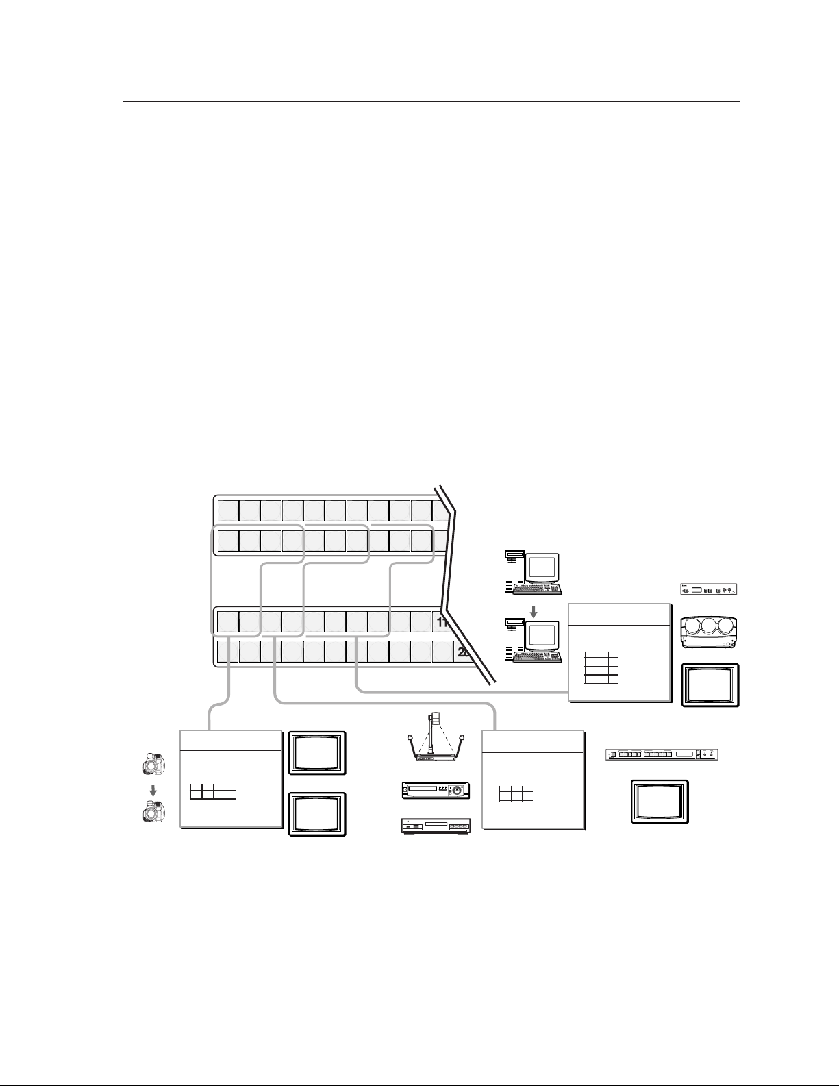
I/O grouping
im Vertrieb von
CAMBOARD Electronics
www.camboard.de
Tel. 07131 911201
Fax 07131 911203
ce-info@camboard.de
I/O grouping is a matrix switcher feature that allows you to subdivide the front
panel control of the matrix into four smaller functional sub-switchers and limit tie
creation from the front panel only. Inputs and outputs can be assigned to one of
four groups or not assigned to any group.
Inputs and outputs that are assigned to a group can only be tied to other outputs
and inputs within the same group when you are creating ties on the front panel.
For example, a front panel operator cannot tie an input that is assigned to group 1
to an output that is assigned to group 2. Ungrouped inputs and outputs can be
switched to outputs and inputs in any group. Ties between groups (an input in
group 1 tied to an output in group 2) can be created under RS-232/RS-422 or
Ethernet control.
Suggested applications for the I/O grouping feature include:
• Segregating specific video formats to prevent an input in one video format
• Segregating input and output devices that are in separate rooms.
• Isolating video from being displayed on specific output devices for
from being inadvertently applied to an output device that supports another
video format (figure 3-29).
operational security reasons.
Camera #1
Camera #4
1 2 3 4 5 6 7 8
171718 19 20 21 22 23 24
Group 1 Group 2 Group 3
1 2 3 4 5 6 7 8
18 19 20 21 22 23 24 25
4 input, 2 output
composite video matrix
Input
17 18 19
20
1
Output
2
Group 1
Figure 3-29 — I/O grouping of incompatible video formats
Monitor
Monitor
9910 11
26 27
25
10
26 27
Document Camera
VCR
DVD
Computer #1
Computer #3
3 input, 2 output
S-video matrix
Input
21 22 23
Group 2
3
4
Output
3 input, 4 output
RGBHV matrix
Input
24 25 26
Group 3
RGB
FREEZE
FREEZE
5
6
Output
7
8
INPUTS
UNIVERSAL
COMPOSITE
12345
S-VIDEO SDI
PICTURE ADJUSTMENTS
CENTER SIZE BRT/CONT COL/TNT ZOOM DETAIL
USP 405
Monitor
FREEZE
RESET
IR
VSC 700
Projector
NEXTMENU
Monitor
ADJUST
MENU
NEXT
USP 405
UNIVERSAL SIGNAL PROCESSOR
VSC 700
SCAN CONVERTER
SIZE
MIN/MAX
CENTER/PAN/SIZE
3-21CrossPoint 450 Plus and MAV Plus Switchers • Operation
Page 62

Operation, cont’d
im Vertrieb von
CAMBOARD Electronics
www.camboard.de
Tel. 07131 911201
Fax 07131 911203
ce-info@camboard.de
The I/O groups can be set up on the front panel or by using RS-232/RS-422 and
Ethernet ports and either the SIS or the Windows control program (see chapter 4,
Programmer’s Guide, and chapter 5, Matrix Software. Create I/O groups on the front
panel as follows:
1. Press the Esc button to clear any input buttons, output buttons, or control
buttons that may be lit.
2. To enter I/O Group mode, press and hold the Input 1 and Output 1 buttons
until the input and output buttons light to display the ungrouped inputs and
outputs.
3. Press and release one of the Control buttons to select a group:
• Press the Enter button to select group 1.
• Press the Preset button to select group 2.
• Press the View button to select group 3.
• Press the Esc button to select group 4.
4. Select the desired input(s) and output(s) to assign to the group by pressing the
input and output buttons.
5. Press and release the RGBHV/Video and Audio button to exit the I/O Group
mode, or allow the mode to time out after approximately 30 seconds.
• Ties between groups (an input in group 1 tied to an output in group 2)
can be created under RS-232/RS-422 or Ethernet control.
• Presets can be created under RS-232/RS-422 or Ethernet control that tie
inputs and outputs across group boundaries. These presets are selectable
from the front panel.
• An input or output can be assigned to only one group. If you assign an
input or output to a group and that input or output is already assigned to
a different group, the older grouping is discarded in favor of the new
grouping.
• Audio
• For I/O groups to have any function, at least two groups must be created.
can be broken away from the video for a given input or output
(assigned to different groups) by isolating only video or only audio using
the front panel RGBHV (CrossPoint 450 Plus)/Video (MAV Plus) and/or
Audio buttons after you select I/O Group mode (between steps 2 and 3).
Audio breakaway across different groups
operating the front panel;
Control Program, HTML pages, or SIS commands; and is
recommended.
is not displayed by the Matrix Switchers
can be confusing when
not
CrossPoint 450 Plus and MAV Plus Switchers • Operation3-22
Page 63

Example 5: Grouping inputs and outputs
im Vertrieb von
CAMBOARD Electronics
www.camboard.de
Tel. 07131 911201
Fax 07131 911203
ce-info@camboard.de
The following steps show an example in which several switcher inputs and outputs
are assigned to groups. The steps show the front panel indications that result from
your action.
1. Press and release the Esc button (figure 3-30).
Press the Esc button to clear all selections.
C O N T R O L
ENTER
PRESET
The button flashes once.
ESCVIEW
Figure 3-30 — Clear all selections
2. To enter I/O Group mode, press and hold the Input 1 and Output 1 buttons
(figure 3-31).
Press and hold the Input 1 button and Output 1 button.
1 2
1 2
17 18
17 18
1 2
1 2
17 18
17 18
I
N
P
U
T
S
2 seconds
O
U
T
P
U
T
S
Release the Input 1 button
and Output 1 button.
Ungrouped input and
output buttons light.
1
1
Figure 3-31 — Select I/O Group mode
3. Press and release the Enter button to select group 1 (figure 3-32).
Press and release the Enter button to select group 1.
The button lights amber to indicate the selection.
C O N T R O L
ENTER
1324Group #
PRESET
ESCVIEW
Figure 3-32 — Select an I/O group
3-23CrossPoint 450 Plus and MAV Plus Switchers • Operation
Page 64

Operation, cont’d
im Vertrieb von
CAMBOARD Electronics
www.camboard.de
Tel. 07131 911201
Fax 07131 911203
ce-info@camboard.de
4. Press and release the input 1 through 4 and output 1 through 4 buttons
(figure 3-33).
Press and release the Input 1 through Input 4 buttons. The selected buttons light.
1 2 3 4 5 6 7 8
17 18 19 20 21 22 23 24
Press and release the Output 1 through Input 4 buttons. The selected buttons light.
1 2 3 4 5 6 7 8
17 18 19 20 21 22 23 24
I
N
P
U
T
S
O
U
T
P
U
T
S
Figure 3-33 — Assign inputs and outputs
5. Press and release the Preset button to select group 2 (figure 3-34).
Press and release the Preset button to select group 2.
The button lights amber to indicate the selection.
C O N T R O L
ENTER
1324Group #
PRESET
ESCVIEW
Figure 3-34 — Select an I/O group
6. Press and release the input 5 through 8 and output 5 through 8 buttons
(figure 3-35).
Press and release the Input 5 through Input 8 buttons. The selected buttons light.
1 2 3 4 5 6 7 8
17 18 19 20 21 22 23 24
Press and release the Output 5 through Output 8 buttons. The selected buttons light.
1 2 3 4 5 6 7 8
17 18 19 20 21 22 23 24
I
N
P
U
T
S
O
U
T
P
U
T
S
Figure 3-35 — Assign inputs and outputs
CrossPoint 450 Plus and MAV Plus Switchers • Operation3-24
Page 65

7. Do nothing for approximately 30 seconds. The front panel times out and the
im Vertrieb von
CAMBOARD Electronics
www.camboard.de
Tel. 07131 911201
Fax 07131 911203
ce-info@camboard.de
switcher exits I/O Group mode.
• Group 1 consists of inputs 1 through 4 and outputs 1 through 4.
• Group 2 consists of inputs 5 through 8 and outputs 5 through 8.
Setting RGB delay (CrossPoint 450 Plus switchers only)
The CrossPoint 450 Plus switchers can briefly blank the RGB (video) output while it
switches to the new input’s sync source, and then switches the RGB signals. This
allows a brief delay for the display to adjust to the selected input’s sync timing
before displaying the new picture, which will appear without glitches. RGB delay,
also known as Triple-Action Switching or video mute switching, is user selectable
from 0 to 5 seconds, in half-second increments.
The RGB delay interval can be set on the front panel or by using RS-232/RS-422
and Ethernet ports and either the SIS, Windows control program, or HTML pages
(see chapter 4, Programmer’s Guide, chapter 5, Matrix Software, and chapter 6, HTML
operation. Specify the RGB delay interval for a specific output on the front panel as
follows:
1. Press the Esc button to clear any input buttons, output buttons, or control
buttons that may be lit.
2. To enter RGB Delay mode, press and hold the RGBHV button until the button
begins to blink green, then release the button.
3. Press and release an output button to select an output. Each lit input button,
from Input 1 through Input 10, indicates a half second of RGB delay interval
for the selected output.
4. Press and release the Esc (
the interval.
5. Press and release the RGBHV button to exit the RGB Delay mode. The
RGBHV button stops blinking.
• Pressing the Enter or Preset button also exits RGB Delay mode. Pressing
the Preset button changes to Recall Preset mode.
• The RGB interval for each output is stored in non-volatile memory. When
power is removed and restored, the delay settings are retained.
• Exiting RGB Delay mode by pressing the RGBHV button always returns
the I/O configuration to audio only selected for configuration.
) and View ( ) buttons to increase and decrease
Example 6: Setting the RGB delay for an output
The following steps show an example in which the RGB delay is increased for
output 17. The steps show the front panel indications that result from your action.
1. Press and release the Esc button (figure 3-36).
Figure 3-36 — Clear all selections
Press the Esc button to clear all selections.
C O N T R O L
ENTER
PRESET
The button flashes once.
ESCVIEW
3-25CrossPoint 450 Plus and MAV Plus Switchers • Operation
Page 66

Operation, cont’d
im Vertrieb von
CAMBOARD Electronics
www.camboard.de
Tel. 07131 911201
Fax 07131 911203
ce-info@camboard.de
2. Press and hold the RGBHV button for approximately 2 seconds (figure 3-37).
RGBHV RGBHV
Figure 3-37 — Select RGB Delay mode
3. Press and release the output 17 button (figure 3-38).
Press and release the
Output 17 button.
The button lights green.
17 18
2 seconds
Press and hold the RGBHV button until it blinks.
= Blinking button
The Input 1 through Input 10 buttons display the selected output's RGB delay.
Each lit input button indicates half a second of delay.
In this example, the green input buttons display 3.5 seconds of RGB delay.
O
1 2
1 2
17 18
U
T
P
U
T
S
1 2 3 4 5 6 7
17 18 19 20 21 22 23
3.53.02.52.01.51.00.5
8 9 10
24 25 26
I
N
P
U
T
S
= Unlit button = Lit button
Figure 3-38 — Select an output
4. Press and release the Esc (
) button once (figure 3-39) to increase the RGB
delay by a half second.
Press and release the Esc (
) button twice more to increase the RGB delay by
a whole second. Note the input button indication changes that occur each
time the Esc (
Figure 3-39 show the result of pressing the Esc (
Press the Esc button to increase the RGB interval that is applied to switches to
the selected output by a half second per button push.
ESC ESC ESC
) button is pressed and released.
) button a total of 3 times.
3.5 4.0 4.5 5.03.02.52.01.51.00.5
1
1 2 3 4 5 6 7
17 18 19 20 21 22 23
The Input 1 through Input 10 buttons display the selected output's RGB delay.
Each lit input button indicates half a second of delay.
In this example, the green input buttons display 5.0 seconds of RGB interval.
= Unlit button = Lit button
8 9 10
24 25 26
I
N
P
U
T
S
Figure 3-39 — Adjust the RGB delay interval
CrossPoint 450 Plus and MAV Plus Switchers • Operation3-26
Page 67

5. Press and release the RGBHV button (figure 3-40).
im Vertrieb von
CAMBOARD Electronics
www.camboard.de
Tel. 07131 911201
Fax 07131 911203
ce-info@camboard.de
Press the RGBHV button
to exit RGB delay mode.
I / O
The RGBHV button stops
blinking and goes out or
becomes background
illuminated.
The Audio button lights red.
Figure 3-40 — Deselect RGB Delay mode
Using presets
The current configuration (configuration 0) can be saved as a preset in any one of
32 preset memory addresses. Preset locations are assigned to the input buttons
and (where necessary) output buttons. Up to 20 or 32 (depending on the number
of input and output buttons) presets can be selected from the front panel to be
either saved or retrieved. When a preset is retrieved from memory, it becomes the
current configuration.
RGBHV AUDIO
All input buttons and output buttons
return to unlit or background illumination.
• Only the audio and video ties are stored and recalled; audio gain settings
are not saved, and they do not change when a preset is recalled.
• Presets cannot be viewed from the front panel unless recalled as the
current configuration. Presets can be viewed using Extron’s Windowsbased control program. See Chapter 5, Matrix Software, for more details.
• The current configuration and all presets are stored in non-volatile
memory. When power is removed and restored, the current configuration
is still active and all presets are retained.
• When a preset is recalled, it replaces the current configuration, which is
lost unless it is also stored as a preset. The recalled preset overwrites all of
the current configuration ties in favor of the preset configuration ties.
• All models have 32 presets; on models with fewer than 32 input and
output buttons, preset numbers that are too high to be available from the
front panel are still accessible under RS-232/RS-422 or Ethernet control.
• Figure 3-41 on the next page shows the presets associated with the various
input and output buttons for all three front panel configurations.
3-27CrossPoint 450 Plus and MAV Plus Switchers • Operation
Page 68

Operation, cont’d
im Vertrieb von
CAMBOARD Electronics
www.camboard.de
Tel. 07131 911201
Fax 07131 911203
ce-info@camboard.de
Input
buttons
Input
buttons
Output
buttons
Input
buttons
Output
buttons
24 x 12, 24 x 24, 32 x 16, and 32 x 32 matrix sizes
Preset
Preset
1
1
Preset3Preset
2
2 3 4 5 6 7 8 9 10 11 12 13 14 15 16
Preset5Preset
4
Preset
6
Preset8Preset
7
Preset
Preset11Preset
10
9
Preset13Preset14Preset
12
15
17 18 19 20 21 22 23 24 25 26 27 28 29 30 31 32
Preset
Preset
17
8 x 16, 16 x 8, and 16 x 16 matrix sizes
Preset
1
1
1
Preset
17
8 x 4, 8 x 8, 12 x 4, and 12 x 8 matrix sizes
Preset
1
1
1
Preset
13
Preset19Preset
18
Preset
Preset
3
2
2
3
2
3
Preset
Preset
19
18
Preset
Preset
2
3
2
3
2
3
Preset14Preset
15
Preset21Preset
20
Preset4Preset
5
4
5
4
5
Preset20Preset
21
Preset
Preset
5
4
4
5
4
5
OUTPUTS
Preset
Preset
17
16
Preset
23
22
Preset6Preset
7
7
6
7
6
Preset22Preset
23
Preset6Preset
7
INPUTS
7
6
7
6
Preset18Preset
19
Preset24Preset
25
Preset8Preset
9
INPUTS
9
8
9
8
OUTPUTS
Preset24Preset
25
Preset
Preset
8
9
9
8
NOTE
8
Preset
20
Preset27Preset
Preset
26
Preset
Preset
10
11
10
11
10
11
Preset
Preset
26
27
Preset
Preset
10
11
10
11
Presets 21 through 32 are available via RS-232/
RS-422 and Ethernet control only
Preset29Preset30Preset
28
Preset13Preset
Preset
12
12
13
13
12
Preset29Preset
Preset
28
Preset
12
12
14
14
14
30
31
Preset15Preset
15
15
Preset31Preset
Preset
16
Preset
32
16
16
16
32
I
N
P
U
T
S
Figure 3-41 — Preset locations by matrix sizes
Example 7: Saving a preset
The following steps show an example in which the current configuration is saved
as a preset. The steps show the front panel indications that result from your action.
1. Press and release the Esc button (figure 3-42).
Press the Esc button to clear all selections.
C O N T R O L
ENTER
PRESET
The button flashes once.
ESCVIEW
Figure 3-42 — Clear all selections
CrossPoint 450 Plus and MAV Plus Switchers • Operation3-28
Page 69

2. Press and hold the Preset button for approximately 2 seconds until it blinks
im Vertrieb von
CAMBOARD Electronics
www.camboard.de
Tel. 07131 911201
Fax 07131 911203
ce-info@camboard.de
(figure 3-43).
2 seconds
PRESET PRESET
Press and hold the Preset button until it blinks.
All input buttons with assigned presets light red.
If you then save the configuration to a lit preset number,
the configuration data at that preset location will be overwritten.
= Blinking button
(Preset Assigned)
1 2
1 2
17 18
17 18
Unlit
(No Preset Assigned)
Figure 3-43 — Enter Save Preset mode
3. Press and release the input or output button for the desired preset
(figure 3-44).
Press and release the Input 1 button.
The button blinks red to indicate that this
preset number is selected but not saved.
1 2 3 4 5 6 7 8
17 18 19 20 21 22 23 24
= Blinking button
I
N
P
U
T
S
C O N T R O L
PRESET
ENTER
The Enter button blinks to
indicate the need to save the
preset.
The Preset button continues
to blink.
Red
I
N
P
U
T
S
ESCVIEW
Figure 3-44 — Select the preset
Figure 3-41 shows the presets associated with the various input and output
buttons for all three front panel configurations.
4. Press and release the Enter button (figure 3-45). The current configuration is
now stored in the selected memory location.
Press the Enter button to
save the preset.
C O N T R O L
PRESET
ENTER
The Enter and Preset
buttons return to unlit or
background illumination.
ESCVIEW
All input buttons return to unlit
or background illumination.
Figure 3-45 — Press the Enter button
3-29CrossPoint 450 Plus and MAV Plus Switchers • Operation
Page 70

Operation, cont’d
im Vertrieb von
CAMBOARD Electronics
www.camboard.de
Tel. 07131 911201
Fax 07131 911203
ce-info@camboard.de
Example 8: Recalling a preset
The following steps show an example in which a preset is recalled to become the
current configuration. The steps show the front panel indications that result from
your action.
1. Press and release the Esc button (figure 3-46).
ENTER
Figure 3-46 — Clear all selections
2. Press and release the Preset button (figure 3-47).
Press the Esc button to clear all selections.
C O N T R O L
PRESET
The button flashes once.
ESCVIEW
Red
(Preset Assigned)
Press and release the Preset button.
PRESET
The Preset button lights.
All input buttons with
assigned presets light red.
1 2
1 2
17 18
17 18
Unlit
(No Preset Assigned)
I
N
P
U
T
S
Figure 3-47 — Enter Recall Preset mode
3. Press and release the input or output button for the desired preset
(figure 3-48).
Press and release the Input 1 button.
The button blinks red to indicate that this
preset number is selected but not recalled.
1 2 3 4 5 6 7 8
17 18 19 20 21 22 23 24
= Blinking button
I
N
P
U
T
S
C O N T R O L
PRESET
ENTER
The Enter button blinks
to indicate the need to
recall the preset.
Figure 3-48 — Select the preset
ESCVIEW
CrossPoint 450 Plus and MAV Plus Switchers • Operation3-30
Figure 3-41 shows the presets associated with the various input and output
buttons for all three front panel configurations.
Page 71

4. Press and release the Enter button (figure 3-49). The configuration stored in
im Vertrieb von
CAMBOARD Electronics
www.camboard.de
Tel. 07131 911201
Fax 07131 911203
ce-info@camboard.de
selected memory location is now the current configuration and can be viewed
in the View-Only mode (see example 4).
Press the Enter button to
recall the preset.
C O N T R O L
PRESET
ENTER ESCVIEW
All input buttons return to unlit or background illumination.
The Enter and Preset
buttons return to unlit or
background illumination.
1 2
1 2
17 18
17 18
I
N
P
U
T
S
Figure 3-49 — Press the Enter button
Muting and unmuting video and/or audio outputs
Individual outputs can be muted or unmuted as follows:
1. Press the Esc button to clear any input button indications, output button
indications, or control button indications that may be on.
2. Press and release the View button.
3. Select video, audio, or both to mute or unmute by pressing the RGBHV
(CrossPoint 450 Plus switchers) or Video (MAV Plus switchers) button and/or
the Audio button.
4. One at a time, press and hold the output button(s) for the desired output(s)
for approximately 2 seconds. The output LED(s) for the selected output(s)
blink to indicate the mute or return to their previous state to indicate the
unmute.
5. Press and release the View button to return to normal switcher operation.
• You can mute video and audio, video-only, or audio-only outputs.
Pressing and releasing the RGBHV (CrossPoint 450 Plus switchers) or
Video (MAV Plus switchers) button and the Audio button toggles each
selection on and off.
• When you enter View-Only mode, the output LEDs turn on for all
outputs without ties.
• On CrossPoint 450 Plus switchers, the video mute function mutes the
R, G, and B planes only; the H and V planes are still active. On
MAV Plus switchers, the video mute function mutes all video planes.
• Mutes are saved to non-volatile memory. When power is removed and
restored, the mute settings are retained.
3-31CrossPoint 450 Plus and MAV Plus Switchers • Operation
Page 72

Operation, cont’d
I / O
VIDEO AUDIO
O
U
T
P
U
T
S
17 18 19 20 21 22 23 24
1 2 3 4 5 6 7 8
Until you select an input, the buttons for all untied outputs light
amber if no inputs are tied, green if no video inputs are tied
(only audio is tied), or red if no audio inputs are tied (only
video is tied).
Until you select an input, the buttons for all untied outputs light
amber if no inputs are tied, green if no video inputs are tied
(only audio is tied), or red if no audio inputs are tied (only
video is tied).
Press the Audio button
to toggle on and off.
The button lights red
when selected.
Press the RGBHV/ Video
button to toggle on and off.
The button lights green
when selected.
im Vertrieb von
CAMBOARD Electronics
www.camboard.de
Tel. 07131 911201
Fax 07131 911203
ce-info@camboard.de
Example 9: Muting and unmuting an output
The following steps show an example in which several switcher outputs are muted
and unmuted. The steps show the front panel indications that result from your
action.
1. Press and release the Esc button (figure 3-50).
ENTER
Figure 3-50 — Clear all selections
2. Press and release the View button to enter View-Only mode. The View button
lights red.
3. To select both video and audio for viewing and muting, if necessary, press
and release the RGBHV (CrossPoint 450 Plus switchers) or Video (MAV Plus
switchers) button and the Audio button (figure 3-51).
Press the Esc button to clear all selections.
C O N T R O L
PRESET
The button flashes once.
ESCVIEW
This example shows the front panel indications if example 1, example 2, and
example 3 have been completed.
Figure 3-51 — Select RGBHV or video and audio
CrossPoint 450 Plus and MAV Plus Switchers • Operation3-32
Page 73

4. One at a time, press and hold the Output 3 and then the Output 4 buttons
im Vertrieb von
CAMBOARD Electronics
www.camboard.de
Tel. 07131 911201
Fax 07131 911203
ce-info@camboard.de
(figure 3-52) for approximately 2 seconds until the buttons begin to blink. The
output 3 and output 4 video and audio signals are muted.
Mute outputs one at a time.
2 seconds
3
Press and hold the Output 3 button.
2 seconds
4
Press and hold the Output 4 button.
= Blinking button
Figure 3-52 — Mute the outputs
If both RGBHV/video and audio are selected, the mute action toggles both the
video and audio outputs. If either the video output or the audio output is
already muted, the unmuted output is muted and the muted output is
unmuted.
If both RGBHV/video and audio are selected and only video is muted, the
output button flashes between green and amber. If only audio is selected, the
output button flashes between red and amber.
5. One at a time, press and hold the Output 3 and then the Output 4 buttons
(figure 3-53) for approximately 2 seconds until the buttons lights steadily. The
output 3 and output 4 video and audio signals are unmuted.
The button blinks amber to indicate that
the RGBHV and audio outputs are muted.
The button blinks amber to indicate that
the RGBHV and audio outputs are muted.
3
4
Mute outputs one at a time.
2 seconds
3
Press and hold the Output 3 button.
2 seconds
4
Press and hold the Output 4 button.
= Blinking button
Figure 3-53 — Unmute the outputs
The button lights amber to indicate that
the RGBHV and audio outputs are not muted.
The button lights amber to indicate that
the RGBHV and audio outputs are not muted.
3
4
3-33CrossPoint 450 Plus and MAV Plus Switchers • Operation
Page 74

Operation, cont’d
im Vertrieb von
CAMBOARD Electronics
www.camboard.de
Tel. 07131 911201
Fax 07131 911203
ce-info@camboard.de
6. Press and release the View button to exit View-Only mode (figure 3-54).
Press the View button
to exit
If both RGBHV/video and audio are selected, the unmute action toggles both
the video and audio outputs. If either the video output or the audio output is
already unmuted, the muted output is unmuted and the unmuted output is
muted.
View-Only
mode.
VIEW
All input buttons and output buttons
return to unlit or background illumination.
The View button returns to
unlit or background
illumination.
Figure 3-54 — Press the View button to exit View-Only mode
Viewing and adjusting the input audio level (audio models)
On models with audio, the audio level of each input can be displayed and adjusted
through a range of -18 dB to +24 dB (-15 dB to +9 dB for MAV Plus 128 AV RCA) to
ensure that there is no noticeable volume difference among sources (figure 3-55).
The audio level can be adjusted from the front panel or under RS-232/RS-422 or
Ethernet control.
VUdBu
21+24
18+21
15+19
12+16
9+13
6+10
3+7
0
+4
-3
+1
-6
-2
-9
-5
-12
-8
-15
-12
-18
-15
-21
-18
Low Audio
Output Level
VUdBu
21+24
18+21
15+19
12+16
9+13
6+10
3+7
0
+4
-3
+1
-6
-2
-9
-5
-12
-8
-15
-12
-18
-15
-21
-18
High Audio
Output Level
Audio
Inputs
Audio
Inputs
VCR
1 2 3 4 5 6 7 8 9 10 11 12 13 14 15 16
17 18 19 20 21 22 23 24 25 26 27 28 29 30 31 32
1 2 3 4 5 6 7 8 9 10 11 12 13 14 15 16
17 18 19 20 21 22 23 24 25 26 27 28 29 30 31 32
I
N
P
U
T
S
C O N T R O L
VIEW
PRESET
ENTER
O
U
T
P
U
T
S
CROSSPOINT xi PLUS SERIES SWITCHER
Crosspoint 450 Plus 3232
CD Jukebox
I / O
ESC
RGBHV
AUDIO
POWER SUPPLY
PRIMARY
REDUNDANT
WITH
ADSP
VUdBu
21+24
18+21
15+19
12+16
9+13
6+10
3+7
0
+4
-3
+1
-6
-2
-9
-5
-12
-8
-15
-12
-18
-15
-21
-18
Output
Level
No noticeable
volume differences
between sources
Audio System
Figure 3-55 — Audio gain and attenuation
1. Press the Esc button to clear any input buttons, output buttons, or control
2. To enter Audio mode, press and hold the Audio button until the button begins
CrossPoint 450 Plus and MAV Plus Switchers • Operation3-34
buttons that may be lit.
to blink red, then release the button.
Page 75

3. Press and release an input button to select an input. The output buttons
im Vertrieb von
CAMBOARD Electronics
www.camboard.de
Tel. 07131 911201
Fax 07131 911203
ce-info@camboard.de
display audio level and polarity (+ or –) for the selected input. Each lit output
button indicates 1 dB of gain or attenuation. Green output buttons indicate a
gain (+) audio level and red buttons indicate an attenuation (–) level.
4. Press and release the Esc (
the audio level.
5. Press and release the Audio button to exit the Audio mode. The Audio button
stops blinking.
• Pressing the Enter or Preset button also exits Audio mode. Pressing the
Preset button changes to Recall Preset mode.
• There is one audio level setting per input. The audio level setting is
shared by the left and right audio inputs.
• The audio level settings are stored in non-volatile memory. When power
is removed and restored, the audio level settings are retained.
• Exiting Audio mode by pressing the Audio button always returns the I/O
configuration to RGBHV (CrossPoint 450 Plus switchers) or video
(MAV Plus switchers) and audio selected for configuration.
) and View ( ) buttons to increase and decrease
Example 10: Viewing and adjusting an input audio level
The following steps show an example in which an audio level is viewed and
adjusted. The steps show the front panel indications that result from your action.
Audio gain and attenuation is displayed differently on different models.
• Switchers with 32 output buttons — Each output button indicates 1 dB when
lit. See the table on page 3-36.
• Switchers with 16 output buttons — Each output button indicates 1 dB when
blinking and 2 dB when lit. See the table on page 3-37.
• Switchers with 8 output buttons — Each output button indicates 1 dB when
blinking slowly, 2 dB when blinking quickly, and 3 dB when lit. See the table
on page 3-37.
Because of the different gain and attenuation display schemes, the input audio
levels that result from the following example are shown three times: as displayed
on a 32-button switcher, on a 16-button switcher, and on an 8-button switcher. The
32-button displays show the actions that led up to the display. For simplicity, the
16-button and 8-button figures show the attenuation display only, not the actions
that lead up to it.
1. Press and release the Esc button (figure 3-56).
Figure 3-56 — Clear all selections
Press the Esc button to clear all selections.
C O N T R O L
ENTER
PRESET
The button flashes once.
ESCVIEW
3-35CrossPoint 450 Plus and MAV Plus Switchers • Operation
Page 76

Operation, cont’d
im Vertrieb von
CAMBOARD Electronics
www.camboard.de
Tel. 07131 911201
Fax 07131 911203
ce-info@camboard.de
Input audio level adjustment displays
CrossPoint 450 Plus /
MAV Plus
2412, 2424, 3216, 3232 HVA
12345678910111213 14 15 16
12
18 19 20 21 22 23 24 25 26 27 28 29 30 31 3217
123456789101112 13 14 15 16
11
18 19 20 21 22 23 24 25 26 27 28 29 30 31 3217
1234567891011 12 13 14 15 16
10
18 19 20 21 22 23 24 25 26 27 28 29 30 31 3217
12345678910 11 12 13 14 15 16
9
18 19 20 21 22 23 24 25 26 27 28 29 30 31 3217
123456789 10111213141516
8
18 19 20 21 22 23 24 25 26 27 28 29 30 31 3217
12345678 9 10 11 12 13 14 15 16
7
18 19 20 21 22 23 24 25 26 27 28 29 30 31 3217
1234567 8 9 10 11 12 13 14 15 16
6
18 19 20 21 22 23 24 25 26 27 28 29 30 31 3217
123456 7 8 9 10 11 12 13 14 15 16
5
18 19 20 21 22 23 24 25 26 27 28 29 30 31 3217
CrossPoint 450 Plus /
MAV Plus
dBdB
12345678910111213141516
24
18 19 20 21 22 23 24 25 26 27 28 29 30 31 3217
12345678910111213141516
23
18 19 20 21 22 23 24 25 26 27 28 29 30 31 3217
12345678910111213141516
22
18 19 20 21 22 23 24 25 26 27 28 29 30 31 3217
12345678910111213141516
21
18 19 20 21 22 23 24 25 26 27 28 29 30 31 3217
12345678910111213141516
20
18 19 20 21 22 23 24 25 26 27 28 29 30 31 3217
12345678910111213141516
19
18 19 20 21 22 23 24 25 26 27 28 29 30 31 3217
12345678910111213141516
18
18 19 20 21 22 23 24 25 26 27 28 29 30 31 3217
12345678910111213141516
17
18 19 20 21 22 23 24 25 26 27 28 29 30 31 3217
2412, 2424, 3216, 3232 HVA
12345 6 7 8 9 10 11 12 13 14 15 16
4
18 19 20 21 22 23 24 25 26 27 28 29 30 31 3217
1234 5 6 7 8 9 10 11 12 13 14 15 16
3
18 19 20 21 22 23 24 25 26 27 28 29 30 31 3217
12345678910111213141516
2
18 19 20 21 22 23 24 25 26 27 28 29 30 31 3217
1 2345678910111213141516
1
18 19 20 21 22 23 24 25 26 27 28 29 30 31 3217
12345678910111213141516
0
18 19 20 21 22 23 24 25 26 27 28 29 30 31 3217
12345678910111213141516
16
18 19 20 21 22 23 24 25 26 27 28 29 30 31 3217
12345678910111213141516
15
18 19 20 21 22 23 24 25 26 27 28 29 30 31 3217
123456789101112131415 16
14
18 19 20 21 22 23 24 25 26 27 28 29 30 31 3217
1234567891011121314 15 16
13
18 19 20 21 22 23 24 25 26 27 28 29 30 31 3217
= unlit button
Green indicates a positive (gain) level,
red indicates a negative (attenuation) level
= lit button
CrossPoint 450 Plus and MAV Plus Switchers • Operation3-36
Page 77

Input audio level adjustment displays
im Vertrieb von
CAMBOARD Electronics
www.camboard.de
Tel. 07131 911201
Fax 07131 911203
ce-info@camboard.de
CrossPoint xi Plus /
MAV Plus
84, 88, 124, 128 HVA
dB dB
24
1 3 4 5 6 7 8
2
23
1 3 4 5 6 7 8
2
22
21
20
19
18
17
16
15
14
13
12
21 3 4 5 6 7 8
1 3 4 5 6 7 8
2
1 3 4 5 6 7 8
2
21 3 4 5 6 7 8
1 3 4 5 6 7 8
2
21 3 4 5 6 7 8
1 3 4 5 6 7 8
2
1 3 4 5 6 7 8
2
21 3 4 5 6 7 8
1 3 4 5 6 7 8
2
1 3 4 5 6 7 8
2
F
S
F
S
24
23
F
22
S
21
20
F
19
S
18
17
16
15
14
13
12
CrossPoint xi Plus /
MAV Plus
816, 168, 1616 HVA
1 3 4 5 6 7 8 9
1 3 4 5 6 7 8 9
1 3 4 5 6 7 8 9
1 3 4 5 6 7 8 9
1 3 4 5 6 7 8 9
1 3 4 5 6 7 8 9
1 3 4 5 6 7 8 9
1 3 4 5 6 7 8 9
1 3 4 5 6 7 8 9
1 3 4 5 6 7 8 9
1 3 4 5 6 7 8 9
10
10
10
10
10
10
10
10
10
10
10
12
112
12
112
12
112
12
112
12
112
12
112
1121 3 4 5 6 7 8 9 10 12
12
112
12
112
12
112
12
112
1121 3 4 5 6 7 8 9 10 12
12
112
14
13
14
13
14
13
14
13
14
13
14
13
13 14
14
13
14
13
14
13
14
13
13 14
14
13
16
15
16
15
16
15
16
15
16
15
16
15
15 16
16
15
16
15
16
15
16
15
15 16
16
15
11
10
21 3 4 5 6 7 8
1 3 4 5 6 7 8
2
9
1 3 4 5 6 7 8
2
8
21 3 4 5 6 7 8
7
1 3 4 5 6 7 8
2
6
1 3 4 5 6 7 8
2
5
1 3 4 5 6 7 8
2
4
1 3 4 5 6 7 8
2
3
1 3 4 5 6 7 8
2
2
1 3 4 5 6 7 8
2
F
1
1 3 4 5 6 7 8
2
S
0
1 3 4 5 6 7 8
F
S
F
S
F
S
1 3 4 5 6 7 8 9
10
1 3 4 5 6 7 8 9
9
1 3 4 5 6 7 8 9
8
1 3 4 5 6 7 8 9
7
1 3 4 5 6 7 8 9
6
1 3 4 5 6 7 8 9
5
1 3 4 5 6 7 8 9
4
1 3 4 5 6 7 8 9
3
1 3 4 5 6 7 8 9
2
1 3 4 5 6 7 8 9
1
1 3 4 5 6 7 8 9
0
1
3 4 5 6127 8 9
10
10
10
10
10
10
10
10
10
10
10
102
11
= Unlit button = Blinking button
= Slow blinking button
S
= Fast blinking button
F
= Lit button
Green indicates a positive (gain) level, red indicates a negative (attenuation) level
12
112
13
12
112
13
12
112
13
12
112
13
12
112
13
12
112
13
12
112
13
12
112
13
12
112
13
12
112
13
12
112
13
112
13
14
14
14
14
14
14
14
14
14
14
14
14
16
15
16
15
16
15
16
15
16
15
16
15
16
15
16
15
16
15
16
15
16
15
15 16
3-37CrossPoint 450 Plus and MAV Plus Switchers • Operation
Page 78

Operation, cont’d
im Vertrieb von
CAMBOARD Electronics
www.camboard.de
Tel. 07131 911201
Fax 07131 911203
ce-info@camboard.de
2. Press and hold the Audio button for approximately 2 seconds (figure 3-57).
AUDIO AUDIO
Figure 3-57 — Select Audio mode
3. Press and release the input 5 button (figure 3-58).
Press and release the Input 5 button.
The button lights green.
2 seconds
Press and hold the Audio button until it blinks.
= Blinking button
1 2 3 4 5 6 7 8
17 18 19 20 21 22 23 24
Green Green Green Green Green Green Green Green
1 2 3 4 5 6 7
17 18 19 20 21 22 23
The output buttons display the selected input's audio level and polarity (gain or attenuation).
Each output button indicates 1 dB when lit.
When the buttons are lit green, they indicate a gain (+) audio level.
When the output buttons are lit red, they indicate an attenuation (-) level.
In this example, the output buttons display an audio gain level of +8 dB.
= Unlit button
Figure 3-58 — Select an input
Figure 3-59 shows the same level (+8 dB) as in figure 3-58, but displayed on a
16-output-button switcher, such as a CrossPoint 450 Plus 816 HVA.
Green Green Green Green
8
24 25 26
I
N
P
U
T
S
9 10
O
U
T
P
U
T
S
Figure 3-59 — Level display on a 16-output-button switcher
CrossPoint 450 Plus and MAV Plus Switchers • Operation3-38
2
1
In this example, the output buttons display an audio gain level of +8 dB.
= unlit button
Figure 3-60 shows the same level (+8 dB) as in figure 3-58, but displayed on a
8-output-button switcher, such as a MAV Plus 84 HDA.
4
3
5
7
6
8
OUT
14
15
16
Page 79

Green Green Green
im Vertrieb von
CAMBOARD Electronics
www.camboard.de
Tel. 07131 911201
Fax 07131 911203
ce-info@camboard.de
2
1
In this example, the output buttons display an audio gain level of +8 dB.
4
3
F
OUTPUTS
6
5
8
7
= unlit button = fast blinking button
Figure 3-60 — Level display on a 8-output-button switcher
4. Press and release the View (
audio level by 1 dB.
Press and release the View (
decrease the input audio level by 1 dB per button push. Note the output
button indication changes that occur each time the View (
Figure 3-61 shows the result of pressing the View (
Note that the level is now displayed in red to indicate a negative level.
Press the View button to decrease the
input audio level by 1 dB per button
VIEW
Red
1
2 3 4 5 6 7 8
17 18 19 20 21 22 23
F
) button once (figure 3-61) to decrease the input
) button several more times (figure 3-61) to
) button is pressed.
) button a total of 9 times.
O
9 10
24 25 26
U
T
P
U
T
S
= Unlit button
The output buttons display the selected input's audio level and polarity (gain or attenuation).
Each output button indicates 1 dB when lit.
When the buttons are lit green, they indicate a gain (+) audio level.
When the output buttons are lit red, they indicate an attenuation (-) level.
In this example, the output buttons display an audio attenuation level of -1 dB.
Figure 3-61 — Adjust the input audio level
Figure 3-62 shows the same level (–1 dB) as in figure 3-61, but displayed on a
16-output-button switcher, such as a MAV Plus 1616 A.
Red
2
1
In this example, the output buttons display an audio gain level of -1 dB.
= unlit button = blinking LED
Figure 3-62 — Level display on a 16-output-button switcher
4
3
5
7
6
8
OUT
14
15
16
3-39CrossPoint 450 Plus and MAV Plus Switchers • Operation
Page 80

Operation, cont’d
im Vertrieb von
CAMBOARD Electronics
www.camboard.de
Tel. 07131 911201
Fax 07131 911203
ce-info@camboard.de
Figure 3-63 shows the same level (–1 dB) as in figure 3-61, but displayed on a
8-output-button switcher, such as a CrossPoint 450 Plus 128 HVA.
In this example, the output buttons display an audio gain level of +8 dB.
Red
1
2
S
4
3
OUTPUTS
6
5
8
7
= unlit button = Slowly blinking button
Figure 3-63 — Level display on a 8-output-button switcher
5. Press and release the Audio button (figure 3-64).
Press the Audio button
to exit audio mode.
I / O
RGBHV AUDIO
The Audio button stops
blinking and lights red.
The RGBHV or Video
button lights green.
Figure 3-64 — Deselect Audio mode
1
S
All input buttons and output buttons
return to unlit or background illumination.
Viewing and adjusting the output volume (audio models)
On models with audio, the audio level of each output can be displayed and
adjusted through a range of 100% (no attenuation) to 0% (maximum [98 dB]
attenuation). The audio level can be adjusted from the front panel or under
RS-232/RS-422 or Ethernet control.
1. Press the Esc button to clear any input buttons, output buttons, or control
2. To enter Audio mode, press and hold the Audio button until the button begins
3. Press and release an output button to select an output. The input buttons
4. Press and release the Esc (
CrossPoint 450 Plus and MAV Plus Switchers • Operation3-40
buttons that may be lit.
to blink red, then release the button.
display the volume level for the selected output. The switchers indicate the
volume differently, depending on number of input buttons, but as a general
rule, the more buttons that are lit, the higher the volume. The fewer buttons
that are lit, the lower the volume.
For a more detailed analysis of decoding the displayed value, see Reading the
displayed volume on the next page.
) and View ( ) buttons to increase and decrease
the audio volume.
Page 81

5. Press and release the Audio button to save the audio settings and exit the
im Vertrieb von
CAMBOARD Electronics
www.camboard.de
Tel. 07131 911201
Fax 07131 911203
ce-info@camboard.de
Audio mode. The Audio button stops blinking.
• There is one audio volume level setting per output. The audio level setting
is shared by the left and right audio inputs.
• The audio volume levels are stored in non-volatile memory. When power
is removed and restored, the audio level settings are retained.
• Exiting Audio mode by pressing the Audio button always returns the I/O
buttons to RGBHV (CrossPoint 450 Plus) or Video (MAV Plus) lit green
and Audio lit red.
• Pressing the Enter or Preset button also exits Audio mode. Pressing the
Preset button changes to Recall Preset mode.
Reading the displayed volume
This section is a detailed look at reading the output volume display on the
switcher’s front panel. If you do not need to read the exact value of the volume
setting, skip this section.
There are 65 steps of volume attenuation, with 1 dB per step (button push), except
for 0-to-1, which is 35 dB. At maximum attenuation, no input buttons are lit, 98 dB
of attenuation is applied, and the audio output is effectively muted. At no
attenuation, all input buttons are lit and the output volume is equal to the input
signal plus any gain or attenuation that is applied to that specific input using the
input audio level adjustment. See Viewing and adjusting the input audio level (audio
models). Other than the minimum and maximum volume, the switchers indicate
the volume differently, depending on number (12, 16, or 32) of input LEDs. See the
table on the next page to read the volume display for each display scheme.
For each display scheme, the input buttons blink or light sequentially to indicate
the approximate volume of the selected output. Volume is defined as a percentage
of the input audio signal that is applied to the output. From 0% of volume, the first
Esc (
) button push applies 5.5% of the input audio signal. From 5.5% on, each
Esc (
) push applies 1.5% more of the input audio signal to the output:
• Push Esc (
! Switchers with 12 and 16 input buttons — Indicated by the Input 1
button blinking slowly.
! Switchers with 32 input buttons — Indicated by the Input 1 button lit
steadily.
• Push Esc (
! Switchers with 12 input buttons — Indicated by the Input 1 button
blinking quickly.
! Switchers with 16 input buttons — Indicated by the Input 1 button lit
steadily.
! Switchers with 32 input buttons — Indicated by the Input 1 and Input 2
button lit steadily.
• Push Esc (
! Switchers with 12 input buttons — Indicated by the Input 1 through 4
buttons lit steadily.
! Switchers with 16 input buttons — Indicated by the Input 1 through 5
buttons lit steadily and the Input 6 button blinking.
! Switchers with 32 input buttons — Indicated by the Input 1 through
Input 11 buttons lit steadily and the Input 12 button blinking.
) button — 5.5% + 1.5% = 7% volume
) button twice — 7% + 1.5% + 1.5% = 10% volume
) button nineteen times — 10% + (19•1.5%) = 38.5% volume
3-41CrossPoint 450 Plus and MAV Plus Switchers • Operation
Page 82

Operation, cont’d
im Vertrieb von
CAMBOARD Electronics
www.camboard.de
Tel. 07131 911201
Fax 07131 911203
ce-info@camboard.de
Audio volume adjustment settings
Highest # input button lit
12-input
switcher
None
Slow
1
blink
Fast
1
blink
Slow
2
blink
Fast
2
blink
2
Slow
3
blink
Fast
3
blink
3
Slow
4
blink
Fast
4
blink
4
Slow
5
blink
Fast
5
blink
5
Slow
6
blink
Fast
6
blink
16-input
switcher
None
32-input
switcher
1
1
2
2
3
3
4
4
5
5
6
6
7
7
8
8
1
1
2
2
31
3
4
4
5
5
6
6
7
7
8
8
9
9
10
10
11
11
12
12
13
13
14
14
15
15
16
16
dB of
attenuation
98
63
62
61
60
59
58
57
56
55
54
53
52
51
50
49
48
47
46
45
44
43
42
41
40
39
38
37
36
35
34
33
32
Output
volume
0%None
5.5%
7%
8.5%
10%
11.5%
13%
14.5%
16%
17.5%
19%
20.5%
22%
23.5%
25%
26.5%
28%
29.5%
31%
32.5%
34%
35.5%
37%
38.5%
40%
41.5%
43%
44.5%
46%
47.5%
49%
50.5%
52%
Highest # input button lit
12-input
switcher
Fast
6
blink
6 9
Slow
7
blink
Fast
7
blink
7
Slow
8
blink
Fast
8
blink
8
Slow
9
blink
Fast
9
blink
9
Slow
10
blink
Fast
10
blink
10
Slow
11
blink
Fast
11
blink
11
Slow
12
blink
Fast
12
blink
12
16-input
switcher
32-input
switcher
9
10
10
11
11
12
12
13
13
14
14
15
15
16
16
17
17
18
18
19
19
20
20
21
21
22
22
23
23
24
24
25
25
26
26
27
27
28
28
29
29
30
30
31
31
32
32
dB of
attenuation
31 53.5%
30 55%
29
28
27
26
25
24
23
22
21
20
19
18
17
16
15
14
13
12
11
10
9
8
7
6
5
4
3
2
1
0
= blinking LED
Output
volume
56.5%
58%
59.5%
61%
62.5%
64%
65.5%
67%
68.5%
70%
71.5%
73%
74.5%
76%
77.5%
79%
80.5%
82%
83.5%
85%
86.5%
88%
89.5%
91%
92.5%
94%
95.5%
97%
98.5%
100%
CrossPoint 450 Plus and MAV Plus Switchers • Operation3-42
Page 83

When all input buttons are lit for any switcher model, the audio output is 100% of
im Vertrieb von
CAMBOARD Electronics
www.camboard.de
Tel. 07131 911201
Fax 07131 911203
ce-info@camboard.de
the audio input level.
Another way to view the volume level is to think in terms of the attenuation that is
applied to the output. Attenuation reduction is indicated by the lit or blinking
input buttons: when fewer input buttons are lit, attenuation is greater (and the
volume is quieter).
• At minimum volume, all input buttons are unlit or background illuminated
and 98 dB of attenuation is applied to the output. The audio output is
effectively muted.
• The first step of volume increase causes the Input 1 button to blink (slowly, in
the case of switchers with 12 input buttons). Attenuation is reduced by 35 dB
(63 dB of attenuation is applied to the output).
• The second step of volume increase reduces the attenuation by an additional
1 dB (62 dB of attenuation is applied to the output). (On switchers with 32
input buttons the Input 1 button lights steadily.)
• Successive steps of volume increase cause consecutive buttons to first blink,
then light steadily. (On switchers with 32 input buttons, each consecutive
button indicates a 1 dB attenuation reduction when blinking and a 2 dB
attenuation reduction when lit.)
For example: When lit steadily, the Input 3 button indicates the following,
depending on the number of input buttons the switcher has:
! Switchers with 12 input buttons — 47 dB of attenuation when compared
to the Input 3 button blinking quickly (48 dB to 50 dB of attenuation).
The blinking Input 4 button (45 dB to 46 dB of attenuation) is at least 2 dB
less than the fast blinking Input 3 button (48 dB – 46 dB) and at most 5 dB
less (50 dB – 45 dB).
! Switchers with 16 input buttons — 52 dB of attenuation when compared
to the Input 3 button blinking (53 dB to 55 dB of attenuation). The
blinking Input 4 button (49 dB to 51 dB of attenuation) is at least 2 dB less
than the fast blinking Input 3 button (53 dB – 51 dB) and at most and at
most 6 dB less (55 dB – 49 dB).
! Switchers with 32 input buttons — 58 dB of attenuation when compared
to the Input 3 button blinking (59 dB of attenuation). The blinking Input
4 button (57 dB of attenuation) is 2 dB less than the steadily-lit Input 2
button (59 dB - 57 dB).
See the table on page 3-42 to read the volume display.
• On switcher with 32 input buttons, the buttons’ volume indications are
additive.
For example: Input 1 lit (36 dB [35 dB + 1 dB] of attenuation reduction), Input
2 lit (2 dB [1 dB + 1 dB] of attenuation reduction), and Input 3 blinking (1 dB
of attenuation reduction) indicate that the output attenuation has been
reduced by a total of 39 dB (36 dB + 2 dB + 1 dB = 39 dB).
• At full volume, no attenuation is applied to the output and all input buttons
are lit steadily.
3-43CrossPoint 450 Plus and MAV Plus Switchers • Operation
Page 84

Operation, cont’d
im Vertrieb von
CAMBOARD Electronics
www.camboard.de
Tel. 07131 911201
Fax 07131 911203
ce-info@camboard.de
Example 11: Viewing and adjusting an output volume level
The following steps show an example in which the audio output volume is viewed
and adjusted. The steps show the front panel indications that result from your
action.
Audio output volume is displayed differently on different models. See the table on
page 3-42.
For this reason, figure 3-68 and figure 3-71 show the indications displayed on a
switcher with 12 output buttons without duplicating all of the actions shown in
figure 3-67 and figure 3-70, which show switchers with 32 output buttons.
Figure 3-69 and figure 3-72 show the indications displayed on a switcher with 16
output buttons.
1. Press and release the Esc button (figure 3-65).
ENTER
Figure 3-65 — Clear all selections
Press the Esc button to clear all selections.
C O N T R O L
PRESET
The button flashes once.
ESCVIEW
2. Press and hold the Audio button for approximately 2 seconds (figure 3-66).
2 seconds
AUDIO AUDIO
Press and hold the Audio button until it blinks.
= Blinking button
Figure 3-66 — Select Audio mode
3. Press and release the output 17 button (figure 3-67).
The input buttons display the selected output's audio volume level.
Each lit input button beyond input 1 indicates 3 percent of the total input volume is applied to the
output. The flashing button indicates an additional 1.5 percent.
In this example, the green input buttons indicate 41.5 percent of the applied audio input. The unlit
input buttons indicate an audio volume attenuation of 39 dB.
Press and release
the Output 17 button.
The button lights
green.
= Unlit button = Blinking button = Lit button
1
17
O
U
T
P
U
T
S
1
2
17 18
3
19
–39 dB attenuation,
41.5% volume
12 13 14 15 16
1
2
28 29 30 31 32
7
I
N
P
U
T
S
Figure 3-67 — Select output 17
CrossPoint 450 Plus and MAV Plus Switchers • Operation3-44
Page 85

Figure 3-68 shows the same volume (41.5%) as in figure 3-67, but displayed on
im Vertrieb von
CAMBOARD Electronics
www.camboard.de
Tel. 07131 911201
Fax 07131 911203
ce-info@camboard.de
a 12-ouput-button switcher, such as a CrossPoint 450 Plus 128 HVA.
The input LEDs display the selected output's audio volume level.
In this example, the lit/blinking input buttons indicate 40 to 41.5 percent of the
applied audio input.
The unlit/blinking input buttons indicate an audio volume attenuation of 39 dB to
40 dB.
–39 dB attenuation,
41.5% volume
1 3 4 5 6 7 8 9
= Unlit button = Slow blinking button
Figure 3-68 — Volume display on a 12-output-button switcher
Figure 3-69 shows the same volume (41.5%) as in figure 3-67, but displayed on
a 16-ouput-button switcher, such as a CrossPoint 1616 HVA.
The input LEDs display the selected output's audio volume level.
In this example, the lit/blinking input buttons indicate 41.5 to 44.5 percent of the applied audio input.
The unlit/blinking input buttons indicate an audio volume attenuation of 37 dB to 39 dB.
1 3 4 5 6 7 8 9
= Unlit button
Figure 3-69 — Volume display on a 16-output-button switcher
S
S
–39 dB attenuation,
41.5% volume
10 14
= Blinking button = Lit button
10
11 162
11 122
= Lit button
12
13 15
3-45CrossPoint 450 Plus and MAV Plus Switchers • Operation
Page 86

Operation, cont’d
im Vertrieb von
CAMBOARD Electronics
www.camboard.de
Tel. 07131 911201
Fax 07131 911203
ce-info@camboard.de
4. Press and release the Esc ( ) button once (figure 3-70) to increase the volume
by 1.5%.
Press and release the Esc (
increase the volume by 1.5% per button push. Note the input button
indication changes that occur each time the Esc (
released.
Figure 3-70 show the result of pressing the Esc (
Press the Esc button to decrease the audio attenuation (thereby increasing the
audio level) that is applied to the output volume level by 1 dB per button push.
ESC
) button several more times (figure 3-70) to
) button is pressed and
You can press and hold the Esc ( ) or View ( ) button to ramp the level up
or down by 3 dB per second to the high or low limit.
) button a total of 13 times.
1
17 18 19
The input buttons display the selected output's audio volume level.
Each lit input button beyond input 1 indicates 3 percent of the total input volume
is applied to the output.
In this example, the green input buttons display 61 percent of the applied audio
input. The unlit input buttons indicate an audio volume attenuation of 26 dB.
3
2
2
26 dB attenuation,
61% volume
= Unlit button
12 13 14 15 16
1
28 29 30 31 32
7
= Lit button
I
N
P
U
T
S
Figure 3-70 — Adjust the output audio volume
Figure 3-71 shows the same volume (61%) as in figure 3-70, but displayed on a
12-ouput-button switcher, such as a CrossPoint 450 Plus 450 128 HVA.
The input LEDs display the selected output's audio volume level.
In this example, the lit/blinking input buttons indicate 59.5 to 61percent of the
applied audio input.
The unlit/blinking input buttons indicate an audio volume attenuation of 26 dB to
27 dB.
–26 dB attenuation,
61% volume
Figure 3-71 — Volume display on a 12-output-button switcher
CrossPoint 450 Plus and MAV Plus Switchers • Operation3-46
1 3 4 5 6 7 8 9
= Unlit button = Fast blinking button
F
F
10
11 122
= Lit button
Page 87

Figure 3-72 shows the same volume (61%) as in figure 3-70, but displayed on a
im Vertrieb von
CAMBOARD Electronics
www.camboard.de
Tel. 07131 911201
Fax 07131 911203
ce-info@camboard.de
16-ouput-button switcher, such as a CrossPoint 1616 HVA.
The input LEDs display the selected output's audio volume level.
In this example, the lit/blinking input buttons indicate 59.5 to 62.5 percent of the applied audio input.
The unlit/blinking input buttons indicate an audio volume attenuation of 25 dB to 27 dB.
–26 dB attenuation,
61% volume
1 3 4 5 6 7 8 9
= Unlit button
= Blinking button = Lit button
11 162
10 14
Figure 3-72 — Volume display on a 16-output-button switcher
5. Press and release the Audio button (figure 3-73).
Press the Audio button
to exit audio mode.
I / O
RGBHV AUDIO
The Audio button stops
blinking and lights red.
The RGBHV or Video
button lights green.
All input buttons and output buttons
return to unlit or background illumination.
Figure 3-73 — Deselect Audio mode
Locking out the front panel (Executive mode)
The front panel security lockout limits the operation of the switcher from the front
panel. When the switcher is locked, all of the front panel functions are disabled
except for the View-Only mode functions. See Viewing a configuration on page 3-17.
Other than in View-Only mode, if the user pushes a front panel button when the
switcher is locked, the RGBHV (CrossPoint 450 Plus) or Video (MAV Plus) and
Audio buttons flash twice and return to their previous state.
To toggle the lock on and off, press and hold the RGBHV (CrossPoint 450 Plus) or
Video (MAV Plus) button and the Audio button for approximately two seconds
(figure 3-74).
12
13 15
Press and hold the RGBHV /Video
and Audio buttons simultaneously
to toggle executive mode on or off.
Figure 3-74 — Toggle front panel lock on or off
I / O
VIDEO AUDIO
2 seconds
I / O
VIDEO AUDIO
The RGBHV/ Video
and Audio buttons
blink twice to indicate
the mode change.
Release the buttons.
3-47CrossPoint 450 Plus and MAV Plus Switchers • Operation
Page 88

Operation, cont’d
im Vertrieb von
CAMBOARD Electronics
www.camboard.de
Tel. 07131 911201
Fax 07131 911203
ce-info@camboard.de
Performing a system reset from the front panel
The front panel reset is identical to the
Programmer’s Guide). A system reset clears all ties and presets, all video and audio
mutes, resets all I/O grouping, sets all input audio levels to unity gain (+0 dB), and
sets all output volume levels to 100% (0 dB of attenuation).
Reset the switcher to the factory default settings by pressing and holding the
RGBHV (CrossPoint 450 Plus) or Video (MAV Plus) button and Audio button while
you apply AC power to the switcher (figure 3-75).
The switcher flashes the button indicators green, red, and
amber and then turns them off.
Continue to hold the RGBHV/Video and Audio buttons until all input and output buttons return to
either unlit or to background illumination and the RGBHV or Video and Audio buttons turn on.
Esc
ZXXX SIS command (see chapter 4,
System reset does not reset the Internet protocol (IP) settings or replace userinstalled firmware.
Press and hold the RGBHV/Video and Audio buttons while you apply
power to the switcher.
I / O
VIDEO AUDIO
Power
Release the RGBHV/Video and Audio buttons.
Figure 3-75 — System reset
Background illumination
The buttons on the front panel can be set to provide amber background
illumination at all times or the background illumination can be turned off. To
toggle the background illumination on or off, press and hold the Input 1 and
Input 2 buttons for approximately two seconds (figure 3-76).
Press and hold the Input 1 and Input 2
buttons simultaneously to toggle
background illumination mode on or off.
1 2
17 18
2 seconds
1 2
17 18
I
N
P
U
T
S
I
N
P
Release the Input 1
U
and Input 2 buttons.
T
S
Figure 3-76 — Toggle background illumination on or off
CrossPoint 450 Plus and MAV Plus Switchers • Operation3-48
Page 89

Selecting the RS-232/RS-422 protocol and baud rate
C O N T R O L
PRESET
ENTER
I / O
RGBHV AUDIO
C O N T R O L
PRESET
ENTER
ESCVIEW
ESCVIEW
2 seconds
All Control buttons light with one flashing.
Both I/O buttons light with one flashing.
The flashing Control button indicates the baud rate as follows:
Enter — 9600 Preset — 19200
View — 38400 Esc — 115200
The flashing I/O button indicates the protocol as follows:
RGBHV/Video — RS-232 Audio — RS-422/RS-485
In this example, the port is set to RS-232 at 9600 baud.
Press and hold the Enter, Preset, View, and Esc buttons.
= Blinking button
im Vertrieb von
CAMBOARD Electronics
www.camboard.de
Tel. 07131 911201
Fax 07131 911203
ce-info@camboard.de
The switcher can support either RS-232 or RS-422 serial communication protocol,
and operate at 9600, 19200, 38400, and 115200 baud rates. The settings of these
variables can be viewed and changed from the front panel.
View and configure the switcher’s serial communications settings as follows:
1. To enter Serial Port Configuration mode, simultaneously press and hold all
Control buttons (Enter, Preset, View, and Esc) (figure 3-77).
Figure 3-77 — RS-232/RS-422 and baud rate display
2. Release the Control buttons.
3. To change a value, press and release the button that relates to the desired
value (figure 3-78).
Press and release the button(s) to configure the port as
follows:
Baud rate:
Enter — 9600 Preset — 19200
View — 38400 Esc — 115200
Serial protocol:
RGBHV/Video — RS-232 Audio — RS-422/RS-485
The selected buttons blink and the others remain lit.
In this example, the port is set to RS-422 at 38400 baud.
I / O
RGBHV AUDIO
ENTER
PRESET
C O N T R O L
ESCVIEW
= Blinking button
Figure 3-78 — RS-232/RS-422 and baud rate selection
4. Press and release an input or output button to exit the Serial Port Configuration
mode (figure 3-79).
Press and release an
input or output button.
5
All Control and I/O buttons return to unlit or background illumination.
ENTER
C O N T R O L
PRESET
ESCVIEW
I / O
RGBHV AUDIO
Figure 3-79 — Exit Serial Port Configuration mode
3-49CrossPoint 450 Plus and MAV Plus Switchers • Operation
Page 90

Operation, cont’d
im Vertrieb von
CAMBOARD Electronics
www.camboard.de
Tel. 07131 911201
Fax 07131 911203
ce-info@camboard.de
Rear Panel Controls
The rear panel has a Reset button that initiates four levels of matrix switcher resets.
Press and hold the button while the switcher is running or while you apply power
to the switcher for different reset levels.
Performing soft system resets
The CrossPoint 450 Plus and MAV Plus switchers have three soft resets available
that restore various tiers of switcher settings to their default settings.
• Events (mode 3) reset — This function toggles the monitoring of events on or
off (if events monitoring was on, this function turns it off; if it was on, it is
turned off).
• IP settings (mode 4) reset — The IP settings reset performs the following
functions:
! Enables Arp program capability
! Resets the IP address to the factory default (192.168.254.254)
! Resets the subnet mask to the factory default ()
! Resets the gateway address to its factory default ()
! Resets port mapping to the factory default ()
! Turn DHCP off
! Turn events off
IP settings reset does not replace any user-installed firmware.
• Absolute (mode 5) reset — Absolute reset restores the switcher to the default
factory conditions. This function is identical to the
command, see chapter 4, Programmer’s Guide).
Esc
ZQQQ SIS
CrossPoint 450 Plus and MAV Plus Switchers • Operation3-50
Page 91

Perform a soft reset of the switcher as follows:
im Vertrieb von
CAMBOARD Electronics
www.camboard.de
Tel. 07131 911201
Fax 07131 911203
ce-info@camboard.de
1. Press and hold the Reset button until the front panel RGBHV
(CrossPoint 450 Plus)/Video (MAV Plus) and Audio buttons blink once
(events reset), twice (system reset), or three times (absolute reset) (figure 3-80).
Release, then
immediately
press and release again.
RESETRESETRESET
Release, then
immediately
press and release again.
Release, then
immediately
press and release again.
Events Reset
IP Settings
Reset
Absolute Reset
Press and hold
the Reset button.
RESET
LAN
Press and hold
the Reset button.
RESETRESET
Press and hold
the Reset button.
I / O
3 seconds
Buttons and Reset LED flash once.
6 seconds
Buttons and Reset LED flash twice.
9 seconds
RGBHV AUDIO
1
I / O
VIDEO AUDIO
2
I / O
RGBHV AUDIO
Buttons and Reset LED flash three times.
NOTE The Reset button on switchers with matrix sizes of 24 x 12 and above
have a different appearance and do not have a rear panel Reset LED.
3
Figure 3-80 — Whole switcher and absolute resets
2. Release the Reset button and then immediately press and release the Reset
button again. Nothing happens if the second momentary press does not
occur within 1 second.
3-51CrossPoint 450 Plus and MAV Plus Switchers • Operation
Page 92

Operation, cont’d
im Vertrieb von
CAMBOARD Electronics
www.camboard.de
Tel. 07131 911201
Fax 07131 911203
ce-info@camboard.de
Performing a hard reset
The hard reset function restores the switcher to the base firmware that it shipped
with. After a hard reset, events do not automatically start, but user settings and
files are restored. Perform a hard reset as follows:
1. If necessary, turn off power to the switcher.
2. Press and hold the Reset button on the rear panel while you apply AC power
to the switcher (figure 3-81).
Press and hold the Reset button while you apply power to the
switcher.
The hard reset restores the factory-installed firmware. The switcher reverts to
that factory firmware the next time power is cycled off and on
firmware update is performed before the power cycle.
RESET
LAN
unless a
The switcher flashes the button indicators green,
red, and amber and then turns them off.
Continue to hold the Reset button until all input and output buttons return
to either unlit or to background illumination and the RGBHV or Video and
Audio buttons turn on.
Release the Reset button.
NOTE The Reset button on switchers with matrix sizes of 24 x 12 and above
have a different appearance and do not have a rear panel Reset LED.
Figure 3-81 — Hard reset
Power
Optimizing the Audio (Audio Switchers)
Each individual input audio level can be adjusted within a range of -18 dB to
+24 dB, so there are no noticeable volume differences between sources and for the
best headroom and signal-to-noise ratio. Adjust the audio gain and attenuation as
follows:
1. Connect audio sources to all desired inputs and connect the audio outputs to
output devices such as audio players. See Audio input and output connections
(audio models only), in chapter 2, Installation. For best results, wire all of the
inputs and the outputs balanced.
2. Power on the audio sources, the switcher, and the audio players.
3. Switch among the inputs (see Creating ties, in this chapter), listening to the
audio with a critical ear or measuring the output audio level with test
equipment, such as a VU meter.
4. As necessary, adjust the input audio level of each input (see Viewing and
adjusting the input audio level (audio models), in this chapter) so that the
approximate output level is the same for all selected inputs.
5. As necessary, adjust the output audio level of each input (see Viewing and
adjusting the output volume (audio models), in this chapter).
RESET
CrossPoint 450 Plus and MAV Plus Switchers • Operation3-52
Page 93

Troubleshooting
im Vertrieb von
CAMBOARD Electronics
www.camboard.de
Tel. 07131 911201
Fax 07131 911203
ce-info@camboard.de
This section gives recommendations on what to do if you have problems operating
the CrossPoint 450 Plus or MAV Plus switcher, and it describes an actual image
problem that Extron has encountered.
General checks
1. Ensure that all devices are plugged in and powered on. The switcher is
receiving power if one of the front panel Power Supply LEDs is lit green.
2. Check to see if one or more outputs are muted.
3. Ensure an active input is selected for output on the switcher.
4. Ensure that the proper signal format is supplied.
5. Check the cabling and make corrections as necessary.
6. Call the Extron S
Plasma display S-video problem (CrossPoint 450 Plus switchers only)
Extron has encountered a problem when a CrossPoint 450 Plus switcher routes
S-video that is output by some video conference codecs. Some codecs change the
DC offset on the chrominance (C) so that it is very different from the level on the
luminance (Y). This can cause a plasma display to come up in the wrong size
mode.
With the matrix switcher taken out of the system, the plasma works fine. It looks
like a problem with the matrix switcher, but it is not. The matrix switcher boosts
the bad codec output, which makes the plasma go to the wrong setting.
Solution: Try placing an Extron video DC block adapter, part #26-495-01, on the
luminance (Y) input to the switcher from the codec.
3
Sales & Technical Support Hotline if necessary.
3-53CrossPoint 450 Plus and MAV Plus Switchers • Operation
Page 94

Operation, cont’d
Worksheet Example
26 27 28 29 30 31 32
26 27 28 29 30 31 32
17 18 19 20 21 22 23 24
17 18 19 20 21 22 23 242525
Main
Hall
PJ#1
Main
Hall
PJ#2
Podium
monitor
VCR
(USP 405)
Lobby
monitor
Class
room #1
monitor
Class
room #2
monitor
Demo
room
PJ #1
Demo
rack
monitor
Demo
rack
switcher
Conf.
room
Sound
system
#2
Camera
main
podium
Podium
Mic
PC1
RGB 201
Rxi
Classroom
#1 VCR
(DVS 406)
Classroom
#2 VCR
(DVS 406)
Laptop
RGB 201
Rxi
Demo
wallbox
#1
Demo
wallbox
#2
Demo
wallbox
#3
Demo
wallbox
#4
Demo
wallbox
#5
Demo
wallbox
#6
Demo
wallbox
#7
Demo
wallbox
#8
Demo
rack #1
USP 405
Demo
rack #2
USP 405
Demo
rack #3
USP 405
Demo
rack #4
USP 405
Rack DVD
(DVS)
Floorbox
#1
Floorbox
#2
Floorbox
#3
Floorbox
#4
Audio
CD
VTG
300
Camera
#2
im Vertrieb von
CAMBOARD Electronics
www.camboard.de
Tel. 07131 911201
Fax 07131 911203
ce-info@camboard.de
Configuration Worksheets
Rather than trying to remember the configuration for each preset, use worksheets
to record this information. Make copies of the blank worksheet on page 3-57
(32-input button and -output button switchers) and page 3-59 (16-button switchers)
and use one for each preset configuration. The worksheet accommodates all of the
CrossPoint 450 Plus and MAV Plus models. Cross out all unused or inactive inputs
and outputs. Use different colors for video and audio.
Worksheet example 1: System equipment
Figure 3-82 shows a worksheet for a CrossPoint 450 Plus 2424 HVA in a fictional
organization with the system hardware annotated. Inputs 10, 11, and 21 through 24
have no connections in this organization, so they have been crossed out on the
worksheet. A CrossPoint 450 Plus 2424 does not have inputs 25 through 32, so they
are crossed out. Similarly, outputs 7, 14, 15, 16, and 25 through 32 are crossed out.
Inputs include PCs, an audio CD player, cameras, and an Extron VTG 300. Output
devices include monitors, front and rear projectors, a stereo, and a VCR for
recording presentations.
The Extron VTG 300 video test generator connected to input 12 enables a video test
pattern to be sent to one, several, or all output devices for problem isolation or
adjustment purposes. An audio test tape or CD could be used in a similar manner
to check out the audio components.
Figure 3-82 — Worksheet example 1: System equipment
CrossPoint 450 Plus and MAV Plus Switchers • Operation3-54
Page 95

Worksheet example 2: Daily configuration
Main
Hall
PJ#1
Main
Hall
PJ#2
Podium
monitor
VCR
(USP 405)
Lobby
monitor
Class
room #1
monitor
Class
room #2
monitor
Demo
room
PJ #1
Demo
rack
monitor
Demo
rack
switcher
Conf.
room
Sound
system
#2
Camera
main
podium
Podium
Mic
PC1
RGB 201
Rxi
Classroom
#1 VCR
(DVS 500)
Classroom
#2 VCR
(DVS 500)
Laptop
RGB 201
Rxi
Demo
wallbox
#1
Demo
wallbox
#2
Demo
wallbox
#3
Demo
wallbox
#4
Demo
wallbox
#5
Demo
wallbox
#6
Demo
wallbox
#7
Demo
wallbox
#8
Demo
rack #1
USP 405
Demo
rack #2
USP 405
Demo
rack #3
USP 405
Demo
rack #4
USP 405
Rack DVD
(DVS)
Floorbox
#1
Floorbox
#2
Floorbox
#3
Floorbox
#4
Audio
CD
VTG
300
Camera
#2
Worksheet Example
26 27 28 29 30 31 32
26 27 28 29 30 31 32
17 18 19 20 21 22 23 24
17 18 19 20 21 22 23 242525
im Vertrieb von
CAMBOARD Electronics
www.camboard.de
Tel. 07131 911201
Fax 07131 911203
ce-info@camboard.de
Figure 3-83 continues from worksheet example 1 by showing the video and audio
ties that make up the configuration of preset 1. A solid ink line shows video ties
and a dashed pencil line shows the audio ties.
In this example:
• The image of the presenter, from the main podium camera (input 1), is
displayed:
! In the main hall (output 1)
! In the conference room (output 4) to the overflow crowd
! In the lobby (output 8)
! Tied to the VCR (output 6)
• The presenter has a presentation on her laptop computer (input 4) that is scan
converted and displayed:
! In the main hall (output 2)
! Locally on the podium (output 3)
• The audio from her microphone (input 3) is played:
! In the hall (output 1)
! In the conference room (output 4)
! Sent to the VCR
• Classical music from the CD player (input 5) is played:
! In the background in the main hall on sound system #2 (output 5)
! In the lobby (output 8)
Figure 3-83 — Worksheet example 2: Daily configuration
3-55CrossPoint 450 Plus and MAV Plus Switchers • Operation
Page 96

Operation, cont’d
Main
Hall
PJ#1
Main
Hall
PJ#2
Podium
monitor
VCR
(USP 405)
Lobby
monitor
Class
room #1
monitor
Class
room #2
monitor
Demo
room
PJ #1
Demo
rack
monitor
Demo
rack
switcher
Conf.
room
Sound
system
#2
Camera
main
podium
Podium
Mic
PC1
RGB 201
Rxi
Laptop
RGB 201
Rxi
Demo
wallbox
#1
Demo
wallbox
#2
Demo
wallbox
#3
Demo
wallbox
#4
Demo
wallbox
#5
Demo
wallbox
#6
Demo
wallbox
#7
Demo
wallbox
#8
Demo
rack #1
USP 405
Demo
rack #2
USP 405
Demo
rack #3
USP 405
Demo
rack #4
USP 405
Rack DVD
(DVS)
Floorbox
#1
Floorbox
#2
Floorbox
#3
Floorbox
#4
Audio
CD
32
VTG
300
Camera
#2
Worksheet Example
26 27 28 29 30 31 32
26 27 28 29 30 31 32
17 18 19 20 21 22 23 24
17 18 19 20 21 22 23 242525
im Vertrieb von
CAMBOARD Electronics
www.camboard.de
Tel. 07131 911201
Fax 07131 911203
ce-info@camboard.de
Worksheet example 3: Test configuration
The A/V system in our fictional organization needs to be fine tuned on a regular
basis. Figure 3-84 shows a typical test configuration, with an Extron video test
generator (input 12) generating a test pattern to all monitors (outputs 1, 2, 3, 4, 8, 9,
10, and 12). Sound checks are run from the CD player (input 5) to all audio systems
(outputs 1, 2, 4, 5, and 8).
Figure 3-84 — Worksheet example 3: Test configuration
CrossPoint 450 Plus and MAV Plus Switchers • Operation3-56
Page 97

Input sources
im Vertrieb von
CAMBOARD Electronics
www.camboard.de
Tel. 07131 911201
Fax 07131 911203
ce-info@camboard.de
26 27 28 29 30 31 32
26 27 28 29 30 31 32
Output destinations
32-button switchers configuration worksheet
1 23456789 10111213141516
17 18 19 20 21 22 23 24 25
1 23456789 10111213141516
17 18 19 20 21 22 23 24 25
Preset # Title: Video: Audio:
Fill in the preset number and use colors, or dashes, etc. to make connecting lines.
Indicate if the configuration is for Video, Audio, or both.
3-57CrossPoint 450 Plus and MAV Plus Switchers • Operation
Page 98

Operation, cont’d
im Vertrieb von
CAMBOARD Electronics
www.camboard.de
Tel. 07131 911201
Fax 07131 911203
ce-info@camboard.de
This page was intentionally left blank.
CrossPoint 450 Plus and MAV Plus Switchers • Operation3-58
Page 99

12 13 14 15 16
im Vertrieb von
CAMBOARD Electronics
www.camboard.de
Tel. 07131 911201
Fax 07131 911203
ce-info@camboard.de
11
10 12 13 14 15 16
Input sources
91011
9
Output destinations
16-button switchers configuration worksheet
1 2345678
123 45 678
Preset # Title: Video: Audio:
Fill in the preset number and use colors, or dashes, etc. to make connecting lines.
Indicate if the configuration is for video, audio, or both.
3-59CrossPoint 450 Plus and MAV Plus Switchers • Operation
Page 100

Operation, cont’d
im Vertrieb von
CAMBOARD Electronics
www.camboard.de
Tel. 07131 911201
Fax 07131 911203
ce-info@camboard.de
This page was intentionally left blank.
CrossPoint 450 Plus and MAV Plus Switchers • Operation3-60
 Loading...