

Page 1
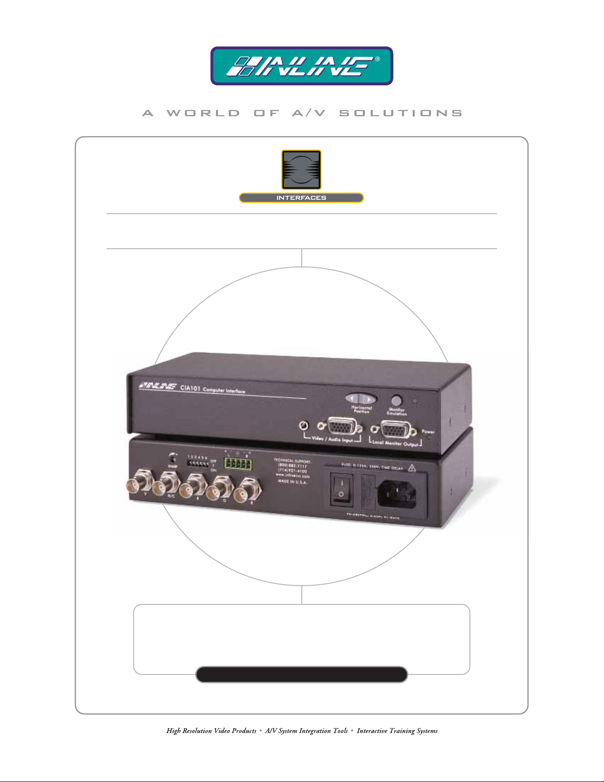
CIA101 COMPUTER INTERFACE
WITH INTERNAL POWER SUPPLY
CIA101
OPER AT ION MANUAL
Page 2
Installation and Safety Instructions
For Models without a Power Switch:
The socket outlet shall be installed near the equipment and shall be accessible.
For all Models:
No serviceable parts inside the unit. Refer service to a qualified technician.
For Models with Internal or External Fuses:
For continued protection against fire hazard, replace only with same type and rating of fuse.
Instructions d’installation et de sécurité
Pour les modèles sans interrupteur de courant:
La prise de courant d’alimentation sera installé près de l’équipement et sera accessible.
Pour tout les modèles:
Pas de composants à entretenir à l’intérieur. Confiez toute réparation à un technicien qualifié.
Pour les modèles équipés de fusibles internes ou externes:
Afin d’éviter tout danger d’incendie, ne remplacer qu’avec le même type et la même valeur de fusible.
Installations- und Sicherheitshinweise
Für Geräte ohne Netzschalter:
Die Netzsteckdose soll in der Nähe des Gerätes installiert und frei zugänglich sein.
Für alle Geräte:
Keine Wartung innerhalb des Gerätes notwendig. Reparaturen nur durch einen Fachmann!
Für Geräte mit interner oder externer Sicherung:
Für dauernden Schutz gegen Feuergefahr darf die Sicherung nur gegen eine andere gleichen Typs und gleicher Nennleistung
ausgewechselt werden.
Instalacion E Instrucciones de Seguridad
Modelos Sin Interruptor:
Para Todos Los Modelos:
Modelos con Fusibles Internos o Externos:
La conexión debe ser instalada cerca del equipo y debe ser accesible.
Dentro de la unidad , no hay partes para reparar. Llame un tecnico calificado.
Para prevenir un incendio, reemplace solo con el mismo tipo de fusible.
CE COMPLIANCE
All products exported to Europe by Inline, Inc. after January 1, 1997 have been tested and found to
comply with EU Council Directive 89/336/EEC. These devices conform to the following
standards:
EN50081-1 (1991), EN55022 (1987)
EN50082-1 (1992 and 1994), EN60950-92
Shielded interconnect cables must be employed with this equipment to ensure compliance with
the pertinent Electromagnetic Interference (EMI) and Electromagnetic Compatibility (EMC)
standards governing this device.
FCC COMPLIANCE
This device has been tested and found to comply with the limits for a Class A digital device,
pursuant to Part 15 of the FCC rules. These limits are designed to provide against harmful
interference when equipment is operated in a commercial environment. This equipment generates,
uses and can radiate radio frequency energy and, if not installed and used in accordance with th e
instruction manual, may cause harmful interference to radio communications. Operation of
equipment in a residential area is likely to cause harmful interference, in which case the user will be
required to correct the interference at their own expense.
Page 3
1
Product Overview
DESCRIPTION
The CIA101 is a high-performance computer interface for analog video and stereo audio signals. The
unit is compatible with a variety of analog signals including VGA, SVGA, XGA, SXGA, UXGA,
MAC, SUN, SGI and other high-resolution workstations. The CIA101’s compact design allows users
to place it in a variety of locations or permanently mount it to virtually any flat surface (using the
optional L mounting brackets). The internal power supply makes it ideal for rental and staging
applications that require a compact, economical, high-performance unit. Like other INLINE
interfaces, the CIA101 performs the following functions:
• Signal Splitting - allows the simultaneous connection and viewing of both the computer's
local monitor and a second output device such as an LCD data projector or a presentation
monitor.
• Physical Interfacing - Because computers employ many different types of video output
connectors, it is sometimes difficult to directly connect them to data projection devices. The
CIA101 simplifies interfacing tasks by acting as a universal adapter. Through the use of
removable input cables, the CIA101 can be attached to different computers and will provide a
video output signal on five BNC connectors. The output signal may be set to RGBHV
(default), RGBS or RGsB formats.
The CIA101 is not a scan converter. The data projector, monitor or other
output device must be compatible with the horizontal scan rate, vertical
PRODUCT FEATURES
• 15-Pin HD Female Connectors - The CIA101 connects directly to PC, MAC and SGI
graphics ports and local monitors via high-resolution coaxial VGA extension / adapter cables.
• Ultra High-Resolution Amplification - The CIA101 provides superb performance with
analog video signals at any resolution.
• Audio Buffering - The CIA101 accepts unbalanced stereo audio from a computer sound card
and can easily be set to output a balanced or unbalanced signal.
• Selectable Output Sync Format - The unit can be set for RGBHV (default), RGBS or RGsB
output sync as required by the data display device and signal distribution system.
• Buffered Local Monitor Output - ensures the highest quality display on a local monitor.
• One-Button Monitor Emulation - makes it easy to use the interface without a local monitor.
• New Soft-Touch Rocker Button for Horizontal Position Control - allows precise centering
of the image within the data display area.
scan rate and resolution output by the computer video card.
©2001 - INLINE, Inc. CIA101 Operation Manual - V1.3 01/03/01
Page 4
2
• Sharpness Control - provides effective image enhancement for high-resolution video signals
by increasing clarity and image detail, and may be used to compensate for signal loss due to
long cable runs.
• Hum Suppression Capability - removes visible effects caused by video ground loops that
exist between the signal source and the interface.
• 400 MHz Bandwidth
• Rack Mountable
Compatibility
INPUT
The CIA101 will accept high-resolution video signals from virtually any computer that outputs an
analog video signal. The unit will work with signals at virtually any resolution and refresh rate.
Compatible comput er vi deo si gnal s i ncl ude VGA, SVGA, XGA, SXGA, UXGA, M AC, SUN, SGI and
other high-resolution computers outputting an analog video signal. Input signal compatibility
parameters are listed below.
Video Signal: Analog RGB Video
Signal format: RGBHV, RGBS, RGsB*
Horizontal Frequency Range: 30 KHz to 130 KHz
Vertical Refresh Rates: 30 Hz to 120 Hz
* The CIA101 will operate with RGsB input signals. However, the unit will
not strip sync off of the green. RGsB input signals are always output as RGsB
(they cannot be output as RGBS or RGBHV). Also, the horizontal position
control will not operate when used with RGsB input signals.
OUTPUT
The output signal of the CIA101 is analog RGB video with TTL sync on 3, 4 or 5 female BNC
connectors. The output format can be set to RGBHV, RGBS or RGsB using dipswitches. This output
signal is compatible with high-resolution data grade monitors and data / graphics projectors.
VGA, MAC, SUN, SGI and other high-resolution workstations operate in
several video modes encompassing a wide range of resolutions and scan
rates. Many of the video signals from the newest models can run as high as
70 KHz or more, with the newest VGA cards offering an output resolution of
1600 x 1200 (some can even go as high as 1920 x 1080). The data projector
or monitor connected to the interface output must be compatible with the
horizontal scan rate and vertical refresh rate of the computer’s video signal.
Please check the documentation for both the computer graphics card and the
data display device to ensure compatibility.
CIA101 Operation Manual - V1.3 01/03/01 ©2001 - INLINE, Inc.
Page 5
3
Installation
This section offers step-by-step instructions for installing the CIA101. An Application Diagram is
provided on page 5, and Front and Rear Panel Connector and Control Diagrams are on page 6. Read the
instructions carefully before initiating the installation procedure. Before you begin, make sure that there
is no power connected to any components in the display system, and that all the power buttons are off.
1.) Place / install the CIA101 at the desired location. The unit may be secured to a flat surface using
the IN9250 L Mounting Brackets (optional), or installed in a standard 19” equipment rack. Two
interfaces can be mounted side-by-side in a 1U rack space (using the optional IN9080 rack shelf).
A single unit can be rack-mounted using the shelf and an optional IN9088 half-rack blank plate.
Run the video coax and the stereo audio cables (if necessary) to the interface..
optional IN9251 Flush Mount Brackets are available for mounting the CIA100 through a
hole in the tabletop.
2.) Set the dipswitches as appropriate for your installation (see page 8 for more details). The CIA101
factory default output format is RGBHV. If your display device, routing system, or cabling require a
different format, use the dipswitches to change the output signal to RGBS or RGsB as necessary. For
best results with high-resolution data projectors / presentation monitors, refer to the Optimal Settings
for LCD / DMD / D-ILA / Plasma Displays Section on page 8.
3.) Turn the computer and computer monitor off. Disconnect the computer monitor (if present) from
the video output port on the computer.
4.) Connect the CIA101 video output (5 BNC connectors) to the data display device's RGB input,
using three, four, or five high-resolution BNC cables or a multi-conductor RGBHV, RGBS, or
RGB "snake". The IN7000 Series, IN7200 Series, IN7300 Series and IN7400P Series highresolution cables are well suited for this purpose. Take care while making connections to ensure
that the red output is connected to the red input, green output to the green input, etc.
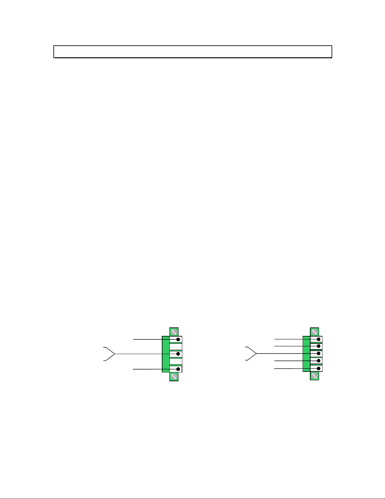
5.) Connect the audio output cable to the appropriate pins on the CIA101 5-pin Phoenix connector.
Make sure that the stereo audio output is connected appropriately for unbalanced or balanced as
required by the installation (see diagram below).
Unbalanced Output - connect to the Left, Right and Ground connectors.
Balanced Output - connect to Left +, Left-, Right+, Right- and Ground connectors.
Note: The
5LJKW
5LJKW
/HIW
/HIW
5LJKW*URXQG
/HIW*URXQG
5LJKW
/HIW
5LJKW*URXQG
/HIW*URXQG
8QEDODQFHG
6.) Connect the computer graphics card to the CIA101 15-pin video input port.
• PC / MAC / SGI Computers with 15-pin HD Video Ports - can be connected via
IN8000M-1 / IN8200M-1 Series high-resolution coaxial VGA cables.
• Older Macintosh (15-pin D) / SUN (13W3) / Workstations (4 or 5 BNC) - can be connected
using the appropriate input / output cables listed in the chart on the next page.
©2001 - INLINE, Inc. CIA101 Operation Manual - V1.3 01/03/01
%DODQFHG
Page 6

4
7.) Connect the computer sound card output (if applicable) to the CIA101 3.5mm female stereo audio
input connector using an IN8200M-1 Series cable [15-pin HD with 3.5mm (M-M) mini DIN], or an
IN9106 audio patch cable (3.5mm stereo mini male to 3.5mm stereo mini male). For computers with
RCA connectors, use the IN9107 audio adapter cable [(1) 3.5mm stereo mini male to (2) RCA male].
8.) Connect the local computer monitor (if applicable) to the local monitor output port of the CIA101.
Monitors with 15-pin VGA connectors will attach directly to the interface. For other types of
monitors, refer to the table below.
If a local monitor is required, disengage the monitor emulation feature by
pressing the Monitor Emulation Button. See page 8 for more details.
9.) Apply power to the CIA101 using the IN9230 IEC power cord (included).
10.) Complete the installation by turning on the computer, the computer monitor and the CIA101 (the
power LED on the front of the unit will illuminate). If required, adjust the sharpness and
horizontal position controls (see page 7 for more details).
ADAPTER / EXTENSION CABLES FOR INPUT AND LOCAL MONITOR OUTPUT
The CIA101 has 15-pin HD VGA-type input and local monitor output connector ports. The following
cables / adapters are available:
Computer 3’ 6’ 12’ 25’ 35’ +
VGA: 15-Pin HD
Input Cable (M-M)
Output Cable (M-F)
VGA with Stereo Audio: 15-Pin HD with 3.5mm (M-M) mini DIN
Input Cable (M-M)
Output Cable (M-F)
MAC with 15-Pin D:
Input Cable (M-M)
Output Cable (M-F)
MAC G3, G4 and PowerBook with 15-Pin HD*:
Input Cable (M-M)
Output Cable (M-F)
SUN: 13W3 (may also be used with SGI with RGsB output)
Input Cable (M-M)
Output Cable (M-F)
Workstation: 5 BNC / RGBHV
Input Cable (M-M)
Output Cable (M-M)
Workstation: 4 BNC / RGBS
Input Cable (M-F)
*Newer Mac G3 models (with translucent cases) have 15-Pin HD connectors (pins arranged in 3 rows).
Older G3 models (with solid white enclosures) incorporate 15-Pin D connectors (pins arranged in 2 rows).
IN8003M-1 IN8006M-1 IN8012M-1 IN8025M-1 IN80xxM-1
IN8006-1 IN8012-1 IN8025-1 IN80xx-1
IN8203M-1 IN8206M-1 IN8212M-1 IN8225M-1 IN82xxM-1
IN8203-1 IN8206-1 IN8212-1 IN8225-1 IN82xx-1
IN9140M IN9144M
IN9141 IN9145
IN8006M-1 IN8012M-1 IN8025M-1 IN80xxM-1
IN8006-1 IN8012-1 IN8025-1 IN80xx-1
IN9142M IN9146M
IN9143 IN9147
IN9045-L6 IN9045-L12 IN9045-L25 IN9045-Lxx
IN9045-L6 IN9045-L12 IN9045-L25 IN9045-Lxx
IN9100
CIA101 Operation Manual - V1.3 01/03/01 ©2001 - INLINE, Inc.
Page 7

5
©2001 - INLINE, Inc. CIA101 Operation Manual - V1.3 01/03/01
Page 8

6
Monitor
Emulation with
LED Indica tor
CIA101 FRONT PANEL CONNECTORS AND CONTROLS
Horizontal
Position
Control
Stereo
Audio
Input
CIA101 REAR PANEL CONNECTORS AND CONTROLS
Dip
Switches
Video
Input
Audio
Output
Connector
( Balanced or Unbalanced )
Local
Monitor
Output
Power
Indicator
Sharpness
Control
Video
Output
Power
Connector
Connectors
CIA101 Operation Manual - V1.3 01/03/01 ©2001 - INLINE, Inc.
Page 9

7
HORIZONTAL POSITION CONTROL
The location of the horizontal position control is shown in the Front Panel Connectors and
Controls diagram on the previous page. Press and release the rocker button to shift the image by
one step to the left or right. Press and hold the button to shift the image continuously.
Note: The horizontal position control has no effect on the local computer monitor.
If the horizontal position adjustment is set to an extreme position on either the display device or
the CIA101, the output image may appear dark and / or the colors may be displayed improperly.
To position the video image and achieve optimum picture quality:
1. Set the display device’s horizontal position control to the center of its adjustment range.
2. Adjust the horizontal position control on the CIA101 until the picture is centered properly
on the display device.
Note: The horizontal position control does not work with RGsB input signals.
SHARPNESS CONTROL
The CIA101 sharpness / peaking circuitry provides variable high frequency equalization that can
compensate for signal losses due to long output cable runs. Careful optimization of the sharpness
control at the time of installation will result in a greatly enhanced image with increased clarity and
edge detail. The amount of high frequency boost required for each display system will vary
depending on the length and bandwidth performance of the video output cables, and, to a lesser
extent, the resolution and frequency of the input signal. When using short output cables, the
sharpness control should usually be placed at the minimum setting to avoid over-peaking.
The sharpness control is located on the back of the interface (see Rear Panel Connectors and
Controls on page 6). Using the IN9339 Adjustment Tool (provided), turn the sharpness control
clockwise to increase the sharpness setting, and counterclockwise to decrease the sharpness
setting. The factory default setting is minimum (no sharpness / peaking enhancement). The
following guidelines are useful in selecting the optimal sharpness / peaking setting:
If the image is soft and / or fine details in the picture lack clarity:
The sharpness is probably set too low. Increase the sharpness control setting.
If a white, ghosted image appears to the right side of the lines / characters:
The sharpness is probably set too high (over-peaked). Decrease the sharpness control
setting.
©2001 - INLINE, Inc. CIA101 Operation Manual - V1.3 01/03/01
Page 10

8
DIPSWITCH SETTINGS
Most installations will not require any changes to the dipswitch settings. The factory default and
specialized dipswitch settings are indicated below.
Factory Default Settings:
Dipswitches ON: 1, 3 & 4
Horizontal Position Control: Enabled
Signal Format: RGBHV
Monitor Emulation at Power Up: Enabled
The table below lists the functions of the 6 dipswitches:
DIPSWITCH FUNCTION SETTING
1
2
3
4
Horizontal Position Control
Output Sync Format
(sync on green)
Output Sync Format
(RGBS or RGBHV)
Monitor Emulation
at power up
On = Enabled*
Off = Disabled
On = RGsB
Off = RGBS / RGBHV*
On = RGBHV*
Off = RGBS
On = Enabled*
Off = Disabled
5 Reserved
6 Reserved
* Factory Default Setting
MONITOR EMULATION
The factory default setting for the CIA101 is Monitor Emulation Enabled. If the application
requires a local monitor, make sure that the front panel Monitor Emulation LED is OFF (press
the MONITOR EMULATION Button to toggle between enabled / disabled). If no local monitor
is necessary, make sure the Monitor Emulation LED is ON.
OPTIMAL SETTINGS FOR LCD / DMD / D-ILA / PLASMA DISPLAYS
Output Sync Format
CIA100 Series Interfaces feature advanced sync processing circuitry that offers superb
compatibility with a wide range of display devices. The CIA101 has been designed (and
extensively tested) to provide excellent operation when set for RGBHV, RGBS and RGsB output
signal formats. However, some display devices most readily identify and display VGA-type
signals when they are in the RGBHV signal format. For this reason, users may achieve optimal
compatibility and more consistent results when the interface is set to the factory default output
sync format of RGBHV (see Dipswitch Settings above).
Horizontal Position Control
The CIA101 horizontal position control utilizes a new circuit design that provides excellent image
quality and greatly enhanced compatibility with a variety of data display technologies. However,
in rare cases, instability in parts of the displayed image may still occur (depending on the design
of the display device's sync circuitry). Adjusting the data display’s fine phase or auto phase
adjustment will usually alleviate the problem. If problems persist, users may wish to disable the
CIA101 horizontal position control (see Dipswitch Settings above).
CIA101 Operation Manual - V1.3 01/03/01 ©2001 - INLINE, Inc.
Page 11

9
Specifications
CIA101 Computer Interface
Input
Connector Type (1) 15-pin HD female - standard VGA pin-outs
RGB Video Signals Analog, 1.5 Vp-p max.
Input Impedance 75 ohm
Sync Signals TTL compatible
Horizontal Scan Rate 30 KHz - 130 KHz
Vertical Sync Range 30 Hz - 120 Hz
Stereo Audio Connector (1) 3.5mm stereo mini female for unbalanced stereo audio
Stereo Audio Compatibility Unbalanced stereo audio; Impedance: 10 kohm
Output
Local Monitor (Buffered) 15-pin HD female - standard VGA pin-outs
Main Output (5) female BNC connectors (on 6” pigtails)
Output Signal Formats RGBHV, RGBS or RGsB
RGB Signals Analog Video, 75 ohm impedance
Bandwidth 400 MHz @ -3 dB with 0.7 Vp-p input signal
Audio Output Connector 5-pin Phoenix connector
Main Audio Output Balanced or unbalanced stereo audio; Impedance: 50 ohm
Dimensions
Size (including faceplate) 1.65” H x 8.5” W x 4.4” D / 4.2 cm x 21.6 cm x 11.1 cm
Product Weight 0.7 lbs. / 0.32 kg.
Shipping Weight 2.4 lbs. / 1.1 kg.
Power
Power Supply Internal universal: 90-260VAC; 47-63 Hz
Regulatory Compliance
Safety UL 1950, CAN/CSA-22.2 No. 950 3rd Ed.
EMI
Parts Included
(1) CIA101 Installation Interface
(1) IN9230 Power Cable, Edison Male to IEC Female, 6' (US only)
(1) IN9339 Adjustment Tool with Technician’s Blade
(1) Operation Manual
Required Accessories (Ordered Separately)
Input and Local Monitor Adapter and Extension Cables:
VGA: IN8000 Series 15-pin HD male to 15-pin HD female, various lengths from 3’ to 100’
For Other Computers: See table on page 4
FCC class A; CE: EN50022 (1987), EN50081-1 (1991),
EN50082-1 (1992 & 1994), EN60950-92
©2001 - INLINE, Inc. CIA101 Operation Manual - V1.3 01/03/01
Page 12

10
Optional Accessories
Audio Input Cables:
IN9106: 3.5mm stereo mini male to 3.5mm stereo mini male, 6’ long
IN9107: (1) 3.5mm stereo mini male to (2) RCA male, 6’ long
Installation Hardware:
IN9080: Rack Shelf - Holds Two Units Side by Side in 1U Rack Space
IN9088B: Half-Rack Blank Plate - Fills Space When Rack Mounting One CIA101
IN9250: L Mounting Brackets - Mounts Unit to a Flat Surface
IN9251: Flush Mount Brackets - Flush Mounts Unit Through Hole in Table Top
RGB Installation Cables
Coaxial Cables 3-Conductor 4-Conductor 5-Conductor
Standard Resolution
Standard Resolution, Plenum
Super High Resolution
Super High Resolution, Plenum
Ultra High Resolution
All cable grades are available in lengths from 3’ to 250’ pre-terminated with high quality BNC connectors or as bulk cable.
IN7000-4 IN7000-5
IN7000P-4 IN7000P-5
IN7300-3 IN7300-4 IN7300-5
IN7400P-5
IN7200-3 IN7200-5 IN7200-6
Troubleshooting
Problem: The display device connected to the CIA101 output has a bad / scrambled image.
Solution 1: Verify that the correct input cable is being used (see table on page 4).
Solution 2: The display device connected to the output of the interface may not be
compatible with the computer output. PC, MAC, SUN and other high-resolution
workstations have new and ultra high-resolution modes such as 1600 x 1200 and
1800 x 1440, and can output a video signal with a horizontal scan rate of over 100 KHz!
Many data monitors and data projectors are not compatible with these resolutions and
frequencies.
Solution 3: Check the dipswitch settings to make sure the unit is putting out a sync
format that the display device can use. For most applications, the default dipswitch
settings will work best (see page 8). For LCD / DMD / D-ILA / Plasma Display devices,
you may have to disable the horizontal position control.
Solution 4: The RGBS or RGBHV cable may have a bad sync line. Try running the sync
through another cable.
Problem: The power LED is on but there is no image on the display device.
Solution: Check the RGBHV cable connections at the interface output and at the
display device input to make sure that the vertical and horizontal sync wires are not
reversed.
CIA101 Operation Manual - V1.3 01/03/01 ©2001 - INLINE, Inc.
Page 13

11
Problem: The power switch is turned on, but the front panel power LED is dark.
Solution 1: Make sure the IN9230 IEC power cable is securely plugged into the unit and the
A/C source.
Solution 2: Make sure the A/C source is live.
Solution 3: The CIA101 contains a 0.125A / 250V time delay fuse. To change the fuse,
remove the power cable, then slide out the fuse holder (located on the rear panel between
the power switch and the IEC cable receptacle) using the IN9339 adjustment tool.
Problem: The output image is very dark.
Solution: The CIA101 horizontal position control may be set off to an extreme setting
or may be interacting poorly with the horizontal position control on the display device.
Follow the horizontal position adjustment procedure on page 7.
Problem: The local monitor looks fine but the image on the Data Projector / Data Display is
wavy or has vertical bars in the picture.
Solution 1: Set the interface to RGBHV output.
Solution 2: Disable the horizontal position control.
Solution 3: LCD / DMD displays often have an adjustment called Phase Adjust or Fine
Phase Control. This control should be adjusted to provide the best image.
Problem: The output image is missing a color.
Solution: Possibly the RGBS or RGBHV cable is bad. Try switching connections on
the output to verify that the bad color’s cable is OK (Example: If there is no red, try
running the green output through the red cable and see if the green is displayed or not).
Problem: The output image is too green.
Solution: The dipswitch settings may be set for sync on green output and the display
device doesn’t work well with that format. Try changing the dipswitches to output an
RGBS or RGBHV signal.
Problem: The horizontal position control is not working.
Solution 1: Check the dipswitch settings to see if the horizontal position control has been
disabled.
Solution 2: The input signal may be RGsB (sync on green). The horizontal position
control does not work with RGsB input signals.
If problems persist, call INLINE Technical Services at (714) 921-4100 for further assistance.
©2001 - INLINE, Inc. CIA101 Operation Manual - V1.3 01/03/01
Page 14

12
Warranty
♦
workmanship.
♦
INLINE warrants the equipment it manufactures to be free from defects in materials and
♦
If equipment fails because of such defects and INLINE is notified within two (2) years
from the date of shipment, INLINE will, at its option, repair or replace the equipment at
its plant, provided that the equipment has not been subjected to mechanical, electrical or
other abuse or modifications.
Equipment that fails under conditions other than those covered will be repaired at the
current price of parts and labor in effect at the time of repair. Such repairs are warranted
for ninety (90) days from the day of re-shipment to the Buyer.
♦
This warranty is in lieu of all other warranties expressed or implied, including
without limitation, any implied warranty or merchantability or fitness for any
particular purpose, all of which are expressly disclaimed.
The information in this manual has been carefully checked and is believed to be accurate. However,
INLINE, Inc. assumes no responsibility for any inaccuracies that may be contained in this manual. In
no event will INLINE, Inc. be liable for direct, indirect, special, incidental, or consequential damages
resulting from any defect or omission in this manual, even if advised of the possibility of such damages.
The technical information contained herein regarding CIA101 features and specifications is sub ject to
change without notice.
Apple, Mac and Macinto sh are registered trademarks of Apple Co mputer, Inc. Sun, Sun Microsystems,
and the Sun Logo are trademarks or registered trademarks of Sun Microsystems, Inc. in the United
States and other countries. SGI is a trademark of Silicon Graphics, Inc. All other trademarks and
registered trademarks are the propert y of thei r respective companies.
All Rights Reserved © Copyright 2001
©
INLINE, INC. ♦ 810 West Taft ♦ Orange, CA 92865
(800) 882-7117 ♦ (714) 450-1800 ♦ FAX (714) 450-1850 ♦ www.inlineinc.com
CIA101 Operation Manual - V1.3 01/03/01 ©2001 - INLINE, Inc.
 Loading...