

Page 1
GAMMA
PRESET MEMORY
VIDEO S-VHS HUE DETAIL
INPUTS
MULTI-STANDARD DECODER
CD 400
INPUTS OUTPUT REMOTE
VIDEO Y C
RG
B H/HV
V
POWER
12V DC
0.8A
H
HV
VIDEO
STD.
SELECT
AUTO
MANUAL
+
-
User's Guide
CD 400
Quad-Standard DECODER
Page 2
Operation
AUTO
MANUAL
Installation and Operation
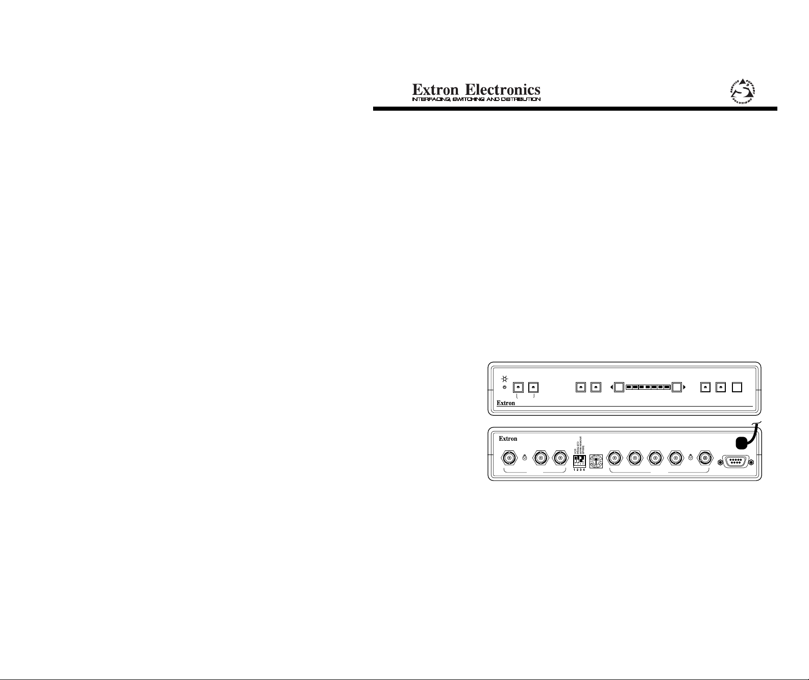
Front Panel Controls and Indicators
Power Indicator LED – Indicates the unit is receiving power.
VIDEO S-VHS HUE DETAIL
INPUTS
Video – Press this button to select the Composite Video input source.
(See Rear Panel.) The LED will light when this input is selected.
S-VHS – Press this button to select the S-VHS input source. The LED
will light when this input is selected. (See Rear Panel connectors.)
Hue – This button allows the Hue (tint) level to be adjusted. Hold the
button while pressing the right or left arrow buttons, the selection
will be indicated on the Range Bar (- +).
Detail – This button is used to adjust the Detail (sharpness). Hold the
button while pressing the right or left arrows, the amount of range
will be indicated on the Range Bar (- +).
Range Bar and -/+ Buttons – This is an LED bar which indicated the
minimum or maximum range scale for Hue and Detail. The (-/+)
buttons are used to make adjustments.
Gamma – This switch turns the Gamma (color) Correction On or Off.
The LED will be lit when Gamma correction is selected. Most
signals are already Gamma-corrected. Additional correction may
make the picture look worse.
Preset – When the LED is lit, the Extron factory presets for Hue,
Detail and Gamma are in effect. When the LED is not lit, user
settings (program) are in effect.
Memory – Each input has memory to store one customized setting.
This button allows those user-programmed settings for Hue, Detail
and Gamma to be saved for the current selected input. This button
becomes effective when it is pressed, and held, until the Hue,
Detail and Gamma LEDs are lit.
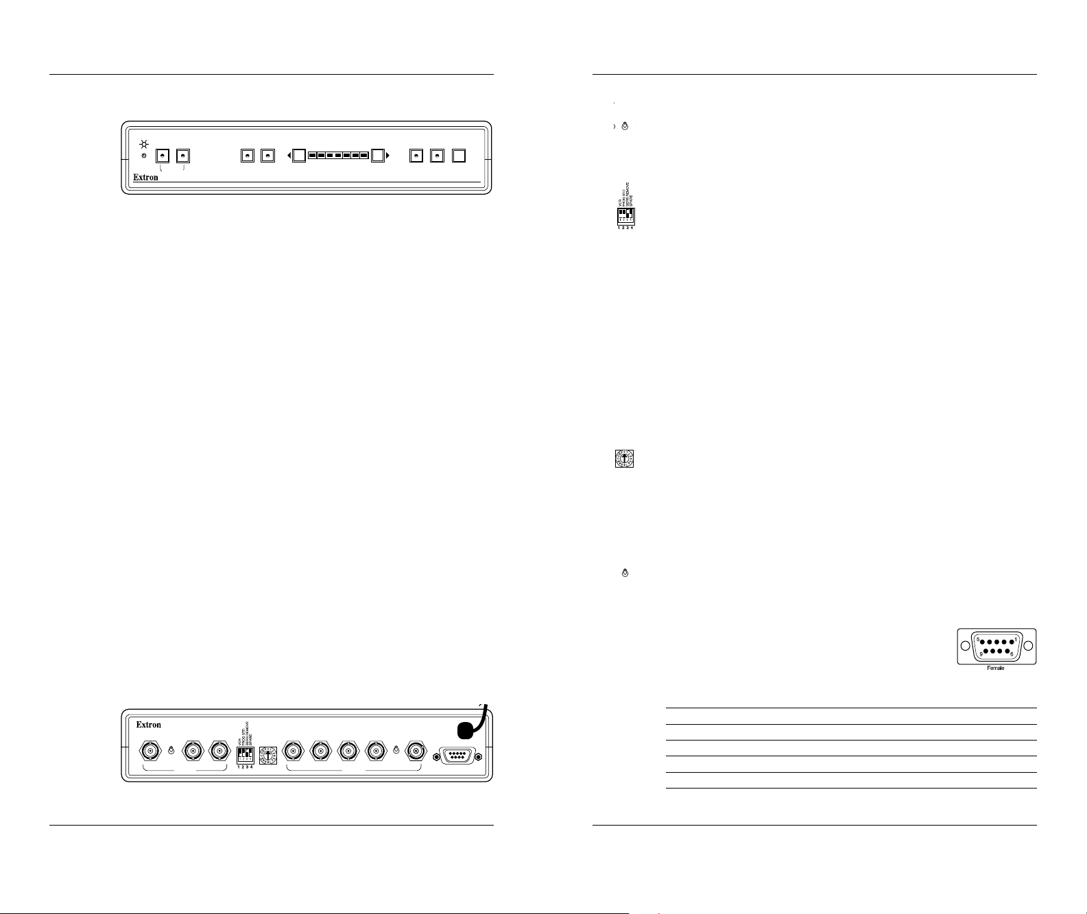
Rear Panel Connectors and Controls
Video Input – This BNC connector is for a Composite Video (NTSC/
PAL/SECAM) input.
VIDEO Y C
AUTO
MANUAL
INPUTS OUTPUT REMOTE
S-VHS (Y/C) Input – These two BNC connectors are for a Y
(luminance) and C (chroma) signal input.
VIDEO
STD.
SELECT
RG
Auto/Manual – When this switch is in the Auto position the CD 400
will automatically select the active input. If both inputs are active,
the Video input will have priority. When the CD 400 is in the
PRESET MEMORY
-
+
GAMMA
MULTI-STANDARD DECODER
CD 400
manual mode of operation the inputs may be selected via the
Front Panel Input switches or by Remote control (Rear Panel).
DIP Switches– The CD 400 has four DIP switches for operation with
the various video standards. Their functions are:
1. VCR – If the input source is a VCR this switch must be in the On
position to compensate for timing variances common with VCRs.
2. Program Standard – With this switch in the On position, the user
may select one of seven preset video standards (described
below). If the video standard is unknown, DIP switch #2 must be
Off, then the CD 400 will automatically select the video standard
which most closely matches the input signal.
3. Serration Remove – Some display devices do not operate
properly when serration pulses are present. When DIP switch #3
is On (up), these pulses will be removed from vertical sync
interval; with the switch Off serration pulses are allowed to pass.
4. Spare (not used)
Video Standard Select – This rotary switch allows the CD 400 to
VIDEO
STD.
SELECT
select from seven video standards. Before using this switch, DIP
switch #2 must be On. The switch positions are as follows:
0 = PAL - B/G, -H, -1, 50 Hz; 1 = PAL +N, 50 Hz;
2 = SECAM 50 Hz; 3 = PAL -M, 60 Hz; 4 = PAL 4.43, 60 Hz;
5 = NTSC, 60 Hz; 6 = NTSC, 4.43, 60 Hz
Output Sync – The CD 400 has two choices for the decoded video
output. This is selected by the H/HV toggle switch located
H
HV
between the H/HV and V connectors. In the H position the output
signal is RGBHV (separate Horizontal and Vertical Sync). In the
HV position the output signal is RGBS (Composite Sync on the
H/HV connector). In the HV position, the V connector is not used.
Remote – This connector allows input selections to be
made by remote control. The Remote port uses a
9-pin connector located on the rear panel with a
pin configuration as follows:
Pin Function Pin Function
1 Composite Video status 2 Not used
3 Not used 4 +5 Vdc (source 50 mA)
5 Ground 6 Common
7 Composite Video select 8 S-VHS select
B H/HV
POWER
12V DC
0.8A
V
H
HV
9 S-VHS status
Examples are listed on the next page.
1
Extron • CD 400 • User’s Guide
Extron • CD 400 • User’s Guide
2
Page 3

Operation and Applications
Examples of remote operation:
• To select Composite Video Input, requires momentary contact
between pins #7 and #6.
• To select S-VHS, requires contact between pins #8, and #6.
• This remote control port also provides a tally output for the selected
input. For example, if Composite Video is the selected input, then
pin #1 (Composite Video status) will have a 4 vdc signal present.
Applications
The illustration here shows a CD 400 used to decode Composite
Video or S-Video from a VCR or a Laserdisc with output to a data
monitor or projector.
Laser Disc Player
The second illustration
shows a CD 400 used in
Video Loopback (VLB)
mode, together with a
system switcher. Details
for this operation are
included in Extron's
System 8/10 Plus
Switcher manual.
This application allows
the CD 400 to decode
any Video or S-Video
signal that comes into
the system switcher.
This saves the cost of
more decoders.
EXTRON ELECTRONICS
1230 South Lewis Street
Anaheim, CA 92805
(714) 491-1500 FAX (714) 491-1517
SM
U.S.A.
VCR
CD 400
Data Monitor
System 8 PLUS Switcher
CD 400 (Decoder)
EXTRON ELECTRONICS, EUROPE
Beeldschermweg 6C
3821 AH Amersfoort
+31-33-453-4040 FAX +31-33-453-4050
The Netherlands
Large Screen Projector
S-Video Sources
Composite Video Sources
EXTRON ELECTRONICS, ASIA
41B Kreta Ayer Road
Singapore 089003
+65-226-0015 FAX +65-226-0019
Singapore
Data Monitor
Large Screen Projector
Output
Inputs
Video Tape Players
Laserdisc Players
Composite
Video out
S-Video
out
68-119-01
69-05
Rev. D
 Loading...