

Page 1
Retractors
Cable Retraction System for Cable Cubby
®
Enclosures
User Guide
Architectural Connectivity
68-1784-01 Rev. B
03 13
Page 2
Safety Instructions
Safety Instructions • English
WARNING: This symbol, , when used on the product, is intended to
alert the user of the presence of uninsulated dangerous voltage within
the product’s enclosure that may present a risk of electric shock.
ATTENTION: This symbol, , when used on the product, is intended
to alert the user of important operating and maintenance (servicing)
instructions in the literature provided with the equipment.
For information on safety guidelines, regulatory compliances, EMI/EMF
compatibility, accessibility, and related topics, see the Extron Safety and
Regulatory Compliance Guide, part number 68-290-01, on the Extron website,
www.extron.com.
Instructions de sécurité • Français
AVERTISSEMENT: Ce pictogramme, , lorsqu’il est utilisé sur le
produit, signale à l’utilisateur la présence à l’intérieur du boîtier
du produit d’une tension électrique dangereuse susceptible de
provoquer un choc électrique.
ATTENTION: Ce pictogramme, , lorsqu’il est utilisé sur le produit,
signale à l’utilisateur des instructions d’utilisation ou de maintenance
importantes qui se trouvent dans la documentation fournie avec le
matériel.
Pour en savoir plus sur les règles de sécurité, la conformité à la réglementation,
la compatibilité EMI/EMF, l’accessibilité, et autres sujets connexes, lisez les
informations de sécurité et de conformité Extron,
réf. 68-290-01, sur le site Extron, www.extron.fr.
Sicherheitsanweisungen • Deutsch
WARNUNG: Dieses Symbol auf dem Produkt soll den Benutzer
darauf aufmerksam machen, dass im Inneren des Gehäuses dieses
Produktes gefährliche Spannungen herrschen, die nicht isoliert sind
und die einen elektrischen Schlag verursachen können.
VORSICHT: Dieses Symbol auf dem Produkt soll dem Benutzer in
der im Lieferumfang enthaltenen Dokumentation besonders wichtige
Hinweise zur Bedienung und Wartung (Instandhaltung) geben.
Chinese Simplified(简体中文)
警告: 产品上的这个标志意在警告用户该产品机壳内有暴露的危险
电 压 ,有 触 电 危 险 。
注意: 产品上的这个标志意在提示用户设备随附的用户手册中有
重要的操作和维护(维修)说明。
关于我们产品的安全指南、遵循的规范、EMI/EMF 的兼容性、无障碍
使用的特性等相关内容,敬请访问 Extron 网站 www.extron.cn,参见 Extron
安全规范指南,产品编号 68-290-01。
Chinese Traditional(繁體中文)
警告: 若產品上使用此符號,是為了提醒使用者,產品機殼內存在著
可能會導致觸電之風險的未絕緣危險電壓。
注意 若產品上使用此符號,是為了提醒使用者。
有關安全性指導方針、法規遵守、EMI/EMF 相容性、存取範圍和相關主題的詳細
資訊,請瀏覽 Extron 網站:www.extron.com,然後參閱《Extron 安全性與
法規遵守手冊》,準則編號 68-290-01。
Japanese
警告: この記 号 が製品上に表示されている場合は、筐体内に絶縁されて
いない高電圧が流れ、感電の危険があることを示しています。
注意: この 記号 が製品上に表示されている場合は、本機の取扱説明書に
記載されている重要な操作と保守(整 備)の指示についてユーザーの
注意を喚起するものです。
安全上のご注意、法規厳守、EMI/EMF適合性、その他の関連項目に
つ い て は 、エク スト ロ ン の ウェ ブ サ イト www.extron.jpより
『Extron Safety and Regulatory Compliance Guide 』 (P/N 68-290-01) をご覧くだ さい 。
Weitere Informationen über die Sicherheitsrichtlinien, Produkthandhabung,
EMI/EMF-Kompatibilität, Zugänglichkeit und verwandte Themen finden Sie in
den Extron-Richtlinien für Sicherheit und Handhabung (Artikelnummer
68-290-01) auf der Extron-Website, www.extron.de.
Instrucciones de seguridad • Español
ADVERTENCIA: Este símbolo, , cuando se utiliza en el producto,
avisa al usuario de la presencia de voltaje peligroso sin aislar dentro
del producto, lo que puede representar un riesgo de descarga
eléctrica.
ATENCIÓN: Este símbolo, , cuando se utiliza en el producto, avisa
al usuario de la presencia de importantes instrucciones de uso
y mantenimiento recogidas en la documentación proporcionada
con el equipo.
Para obtener información sobre directrices de seguridad, cumplimiento
de normativas, compatibilidad electromagnética, accesibilidad y temas
relacionados, consulte la Guía de cumplimiento de normativas y seguridad de
Extron, referencia 68-290-01, en el sitio Web de Extron, www.extron.es.
Korean
경고: 이 기호 , 가 제품에 사용될 경우, 제품의 인클로저 내에 있는
접지되지 않은 위험한 전류로 인해 사용자가 감전될 위험이 있음을
경고합니다.
주의: 이 기호 , 가 제품에 사용될 경우, 장비와 함께 제공된 책자에 나와
있는 주요 운영 및 유지보수(정비) 지침을 경고합니다.
안전 가이드라인, 규제 준수, EMI/EMF 호환성, 접근성, 그리고 관련
항목에 대한 자세한 내용은 Extron 웹 사이트(www.extron.com)의
Extron 안전 및 규제 준수 안내서, 68-290-01 조항을 참조하십시오.
Page 3

Copyright
© 2013 Extron Electronics. All rights reserved.
Trademarks
All trademarks mentioned in this guide are the properties of their respective owners.
The following registered trademarks
(R)
, registered service marks
(SM)
, and trademarks
(TM)
are the property of
RGBSystems, Inc. or Extron Electronics:
Registered Trademarks
AVTrac, Cable Cubby, CrossPoint, eBUS, EDID Manager, EDID Minder, Extron, Flat Field,GlobalViewer, Hideaway, Inline, IP Intercom, IP Link,
Key Minder, LockIt, MediaLink, PoleVault, PowerCage, PURE3, Quantum, SoundField, System Integrator, TouchLink, V-Lock, VersaTools,
VN-Matrix, VoiceLift, WallVault, WindoWall
Registered Service Mark
(SM)
: S3 Service Support Solutions
Trademarks (™
AAP, AFL (Accu-Rate Frame Lock), ADSP (Advanced Digital Sync Processing), AIS (Advanced Instruction Set), Auto-Image, CDRS (Class D
Ripple Suppression), DDSP (Digital Display Sync Processing), DMI (Dynamic Motion Interpolation), Driver Configurator, DSP Configurator, DSVP
(Digital Sync Validation Processing), FastBite, FOXBOX, IP Intercom HelpDesk, MAAP, MicroDigital, ProDSP, QS-FPC (QuickSwitch Front Panel
Controller), Scope-Trigger, SIS, Simple Instruction Set, Skew-Free, SpeedMount, SpeedNav, SpeedSwitch, Triple-Action Switching, XTP, XTP
Systems, XTRA, ZipCaddy, ZipClip
(®)
)
Page 4
Conventions Used in this Guide
Notifications
The following notifications are used in this guide:
DANGER: A danger indicates a situation that will result in death or severe injury.
WARNING: A warning indicates a situation that has the potential to result in death or
severe injury.
CAUTION: A caution indicates a situation that may result in minor injury.
ATTENTION: Attention indicates a situation that may damage or destroy the product or
associated equipment.
NOTE: A note draws attention to important information.
TIP: A tip provides a suggestion to make working with the application easier.
Software Commands
Commands are written in the fonts shown here:
^AR Merge Scene,,Op1 scene 1,1 ^B 51 ^W^C
[01] R 0004 00300 00400 00800 00600 [02] 35 [17] [03]
E X! *X1&* X2)* X2#* X2! CE}
NOTE: For commands and examples of computer or device responses mentioned
in this guide, the character “0” is used for the number zero and “O” is the capital
letter “o.”
Computer responses and directory paths that do not have variables are written in the font
shown here:
Reply from 208.132.180.48: bytes=32 times=2ms TTL=32
C:\Program Files\Extron
Variables are written in slanted form as shown here:
ping xxx.xxx.xxx.xxx —t
SOH R Data STX Command ETB ETX
Selectable items, such as menu names, menu options, buttons, tabs, and field names are
written in the font shown here:
From the File menu, select New.
Click the OK button.
Specifications Availability
Product specifications are available on the Extron website, www.extron.com.
Page 5

Contents
Introduction............................................................ 1
About this User Guide ........................................ 1
About the Cable Retraction System .................... 1
Features ............................................................. 1
Before Getting Started ........................................ 3
Cable Retraction System Overview ..................... 3
Planning ............................................................. 4
Determine Under-table Clearances and
Connections .................................................. 5
CC300, CC600, CC800
Enclosure Clearances .................................... 6
TLP 350CV, TLP 710CV, TLE 350, TLE 710
Enclosure Clearances .................................... 7
All Installations (Except Drop-in) ...................... 8
Prepare the Cable Cubby Enclosure ................... 9
All Installations ................................................ 9
Retrofit Installations ......................................... 9
Prepare the Retractors ..................................... 10
Horizontal or Angular Mounting: .................... 10
Angular Mounting: ........................................ 10
Operation .............................................................. 21
Extend a Cable ................................................ 21
Retract a Cable ................................................ 22
Maintenance and Adjustments ....................... 23
Pulley System Adjustment ................................ 23
To Adjust the Pulley System: ......................... 23
Removing and Replacing the System ............... 25
To Remove the System: ................................ 25
To Replace the System: ................................ 26
Expand the Cable Retraction System ............... 27
Add a Cable Retraction System ........................ 28
Reference Information ...................................... 29
Cable Retraction System Part Numbers ........... 29
Optional Accessories ........................................ 29
Installation ............................................................ 11
Cable Cubby 200 ............................................. 12
CC200 Bracket and Retractor Mounting ...... 13
CC300, CC600, CC800,
TLE, TLP Installation ........................................ 14
Horizontal Bracket Mounting ............................ 15
Locking Screw (Optional) .................................. 17
Alternative Solutions ......................................... 18
Drop-in Installations ...................................... 18
Laptop Power ................................................... 19
Connect the Cables .......................................... 20
Verify Cable Release Operation ......................... 20
vCable Retraction System • Contents
Page 6

Cable Retraction System • Contents vi
Page 7

Introduction
• About this User Guide
• About the Cable Retraction System
• Features
About this User Guide
This guide contains information to install, adjust, and operate Extron Electronics
CableRetractionSystem for CableCubby® Enclosures, and the Extended Length Cable
Retraction System for Cable Cubby
In this guide, the terms “system”, or “retraction system” are used to refer to the
Cable Retraction System for Cable Cubby Enclosures and the Extended Length Cable
Retraction System for Cable Cubby® Enclosures which includes up to three individual
retractors. The term “retractor” refers to an individual retractor in the system, and the term
“enclosure” refers to a Cable Cubby furniture-mountable enclosure. The term “XL” refers to
the XL series. Where differences in preparation, installation, operation, or maintenance may
occur, they are called out.
®
Enclosures.
About the Cable Retraction System
The Cable Retraction System for Cable Cubby Enclosures is a cable retracting device
installed into, but not limited to, Extron Electronics Cable Cubby products. The cable
retraction system can be mounted into all current Cable Cubby products.
The cable retraction system allows extended cables to be retracted back into the Cable
Cubby enclosure for storage without force or gravity. It also prevents cables from tangling
underneath the table as commonly seen with traditional gravity-fed systems. The retractor is
a compact multi-pulley assembly that provides a smooth consistent return motion with the
push of a button.
Each retractor comes pre-loaded with Extron tested and approved cable, optimized for
the specific cable diameter and flexibility. The standard retractor allows up to three feet of
cable to be extended from the top of the enclosure and provides up to six feet of pigtail for
connection of devices under the table. The XL series allows up to five feet of cable extension
and provides up to four feet of pigtail for under-table connections.
The Cable Retraction System is available in cable types to fit all applications. See
www.extron.com for current models.
Features
• Compatible with most Cable Cubby enclosures— The retraction system is easily
integrated with Cable Cubby 300, 600, and 800 series enclosures, the TLESeries
enclosures, and CableCubby TouchLink™Touchpanels (TLP350CV and TLP710CV
only). An adapter is available for installation into the Cable Cubby 200 enclosure.
• Cables extend up to 3 feet (90 cm) (XL series extend up to 5 feet)— Available
6feet (1.8 m) pigtail on standard retractors and 4 feet (1.2 m) pigtail on XL series
retractors for connection to under-table electronics or floor boxes.
Cable Retraction System • Introduction 1
Page 8
• Flexible installation alternatives— Retractor can be installed under a table or other
work surface in either a vertical or horizontal position.
• DC Laptop Power— Refer to the retraction system DC power compatibility list on the
website for laptop compatibility. Always use the power supply recommended by the
laptop manufacturer.
• Filler Modules (optional)— For mounting fewer than three retractors on each side
(fewer than two for the Cable Cubby 200).
• CC 200 Bracket— For Cable Cubby 200 enclosures allows mounting up to two
retractors total.
Extron
Cable Cubby 300C
Mounted in
Horizontal Position
in Cable Cubby 300C
Extron
Cable Retraction System
Figure 1. Cable Retraction System
Cable Retraction System • Introduction 2
Page 9
Before Getting
Started
This section provides an overview of the retractor installation and suggestions for planning
an installation.
• Cable Retraction System Overview
• Planning
• Prepare the Cable Cubby Enclosure
• Prepare the Retractors
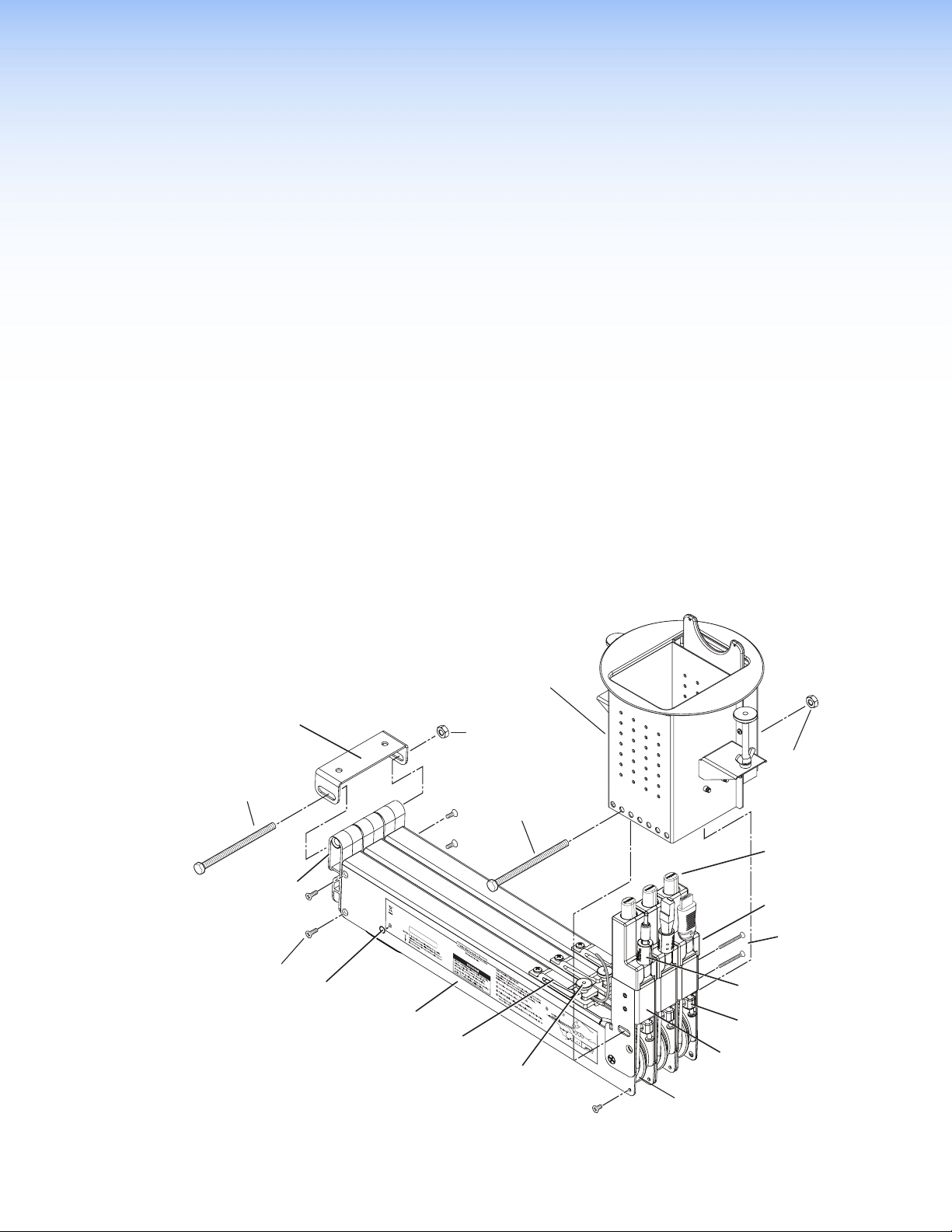
Cable Retraction System Overview
Before beginning an installation, familiarize yourself with the system and the installation to
determine if additional parts or accessories are required.
Horizontal Mounting
Bracket
Horizontal
Mounting Bolt
End Cap Assembly,
With Constant
Spring Assembly
End Cap
Screws (4 ea.)
Pulley System
Alignment Port
Retractor Enclosure
Cable Retainer Clamp
The cable and spring assembly have been
tested and optimized for this model.
Contact Extron Electronics for modifications
or repairs.
Cable Cubby
Enclosure
(not included)
Horizontal
Mounting Nut
Enclosure
Mounting Bolt
Anaheim, CA USA
www.extron.com
Thumbnut
Ver tical Mounting
Screws (2 ea.)
Loosen thumbwheel nut.
DO NOT remove
pulley screws
(ea side).
For horizontal mounting
remove this screw (ea side).
Enclosure
Mounting Nut
Cable Release
Button
Cable Stop
Assembly
Cable Stop
Assembly Screws
Cable Stop Collar
Hold cable.
33-1810-10
Rev. A
Adjustment Block
Upper Arm Assembly
Stationary Pulley
Figure 2. Retraction System Components
Cable Retraction System • Before Getting Started
3
Page 10
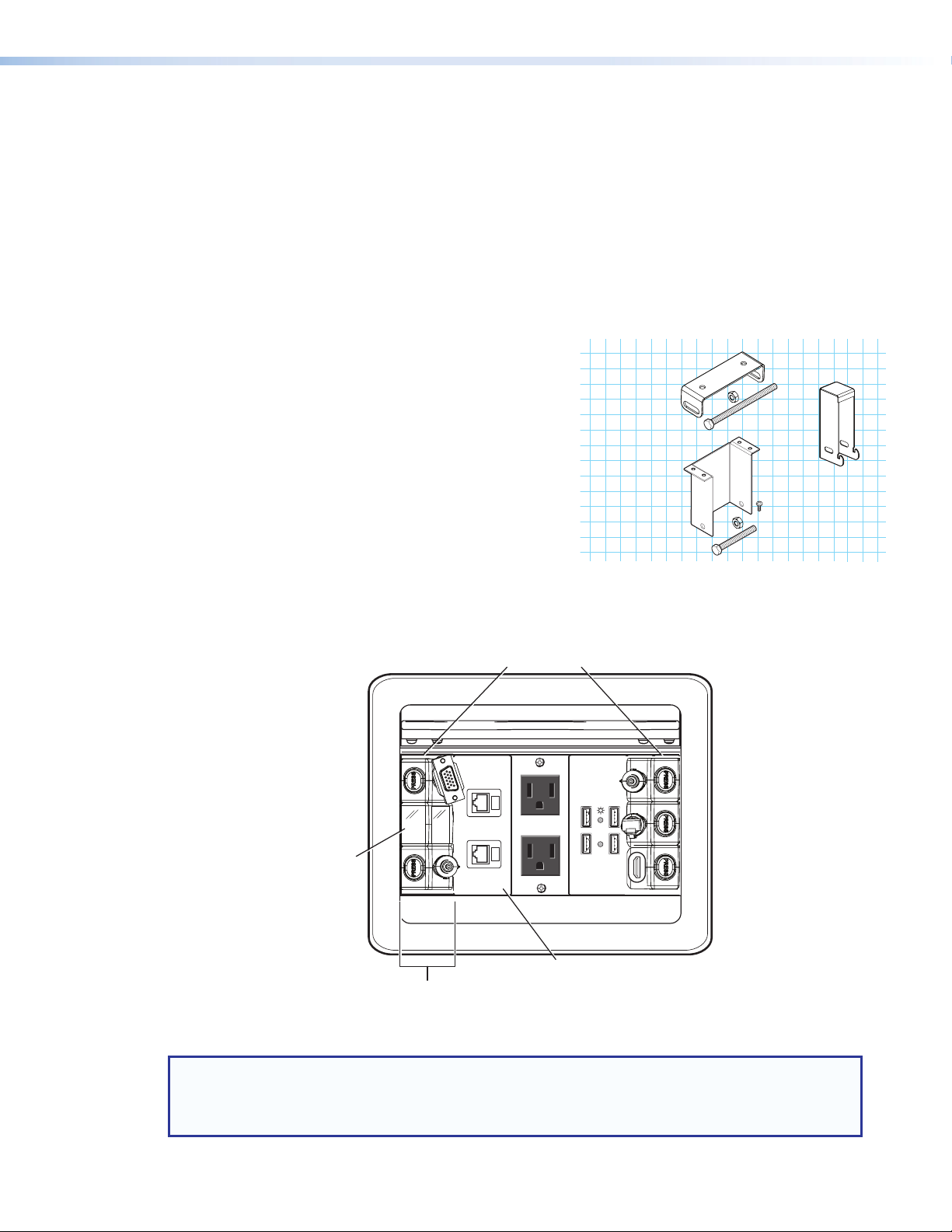
Planning
Filler modules
(part
take up the same
space as one retractor.
The cable retraction system can be mounted horizontally or vertically depending upon
under-table clearance and accessibility.
Horizontal mounting is recommended to provide maximum legroom and to protect the
retractors against accidental damage.
Vertical mounting is used where insufficient under-table space exists for horizontal
mounting or where under-table access is limited.
Angular mounting (XL models only) is used where insufficient under-table space exists
for horizontal mounting and tabletop to floor clearance prevents vertical mounting. The
XL enclosure has additional mounting holes that enable mounting at an angle between
horizontal and vertical.
• For horizontal mounting, a mounting
bracket kit, part number 70-678-00, is
required (see Optional Accessories on
Horizontal Mounting
Bracket (Optional)
Part 70-678-00
page29).
• Filler modules, part number 70-678-08,
may be required to occupy unused retractor
space (see Optional Accessories on
page29).
• For Cable Cubby 200 installation, obtain
CC 200 Mounting Bracket
for Cable Cubby 200
(Optional)
Part 70-678-10
(x4)
Filler Module
(Optional)
Part 70-678-08
the CC 200 bracket kit (see Optional
Accessories on page29).
• For DC Power retractors, refer to the list on
the website for laptop compatibiiity. Always
use a power supply recommended by the laptop manufacturer.
The retraction system must be mounted on either
side of the enclosure with the cable release buttons
CC 800 shown
against the enclosure side walls.
UNSWITCHED
100-240V/ 5AMAX
UNSWITCHED
ACTIVITY
#70-678-08)
Retractors take
two AAP spaces.
USP HUB4 AAP
100-240V/ 5AMAX
Check for adequate cable
clearance inside the
Cable Cubby enclosure.
Figure 3. Retraction System Enclosure Locations
NOTE: When AAP modules are relocated or removed to provide space for the retraction system,
associated AAP brackets may require reconfiguration or replacement. Before starting an
installation determine if replacement AAP brackets will be needed. Replacement brackets can be
ordered from the Extron website.
Cable Retraction System • Before Getting Started 4
Page 11
Pigtail Starts
Here
6’ (1.8 m) Std.
4’ (1.2 m) XL
A Cable Cubby Series Installation Guide with details of the AAP bracket requirements,
along with the horizontal mounting bracket, filler module, CC200 mounting bracket kit,
AAPbrackets, and a laptop compatibility list are available at www.extron.com.
CAUTION:
• Do not operate a retractor until it is installed.
• Keep hands away from moving parts.
Determine Under-table Clearances and Connections
For all retractable system installations be certain there is adequate under-table space
and the retractor pigtail can reach under-table devices. The following diagrams show
the under-table clearances required for installation and operation of the retractor system
mounted in a Cable Cubby, TouchLink, or TLE series enclosure.
NOTES:
• To prevent objects from impeding cable retraction, ensure at least 3 inches of
clearance from the exposed cable side of the retractor enclosure.
• Excess cabling may cause clearance issues. Use zip ties to secure under-table
cabling to prevent accidental contact or entanglement with users.
If there is limited under-table access after the Cable Cubby enclosure is mounted, the
retraction system can be installed before the enclosure is mounted
(see Alternative Solutions on page18).
For CC 200 installations, see Cable Cubby 200 on page 12.
Pigtails
To make connections to devices under the table, standard retractors have 6 feet (1.8m) and
XL retractors have 4 feet (1.2m) of pigtail from the exit of the cable retainer as shown below.
Depending on the retractor mounting and the location of the devices, you may require patch
cables to extend the reach of the pigtail.
6’ (1.8 m) Std.
4’ (1.2 m) XL
Pigtail Starts
Here
Figure 4. Pigtail Length
If you need to connect to devices further than the pigtails allow, contact your Extron
representative or go to www.extron.com for a full line of patch cables.
In vertical installations, the pigtail begins 9.5 inches (24.1 cm) below the table top in
CC200/300/600/800 models for both standard and XL models, and 10.5 inches (26.7 cm)
below the table top for TLP 350CV/710CV and TLE 350/710 enclosures (see figure 5 on
page 6 and figure 6 on page 7).
Cable Retraction System • Before Getting Started 5
Page 12
For new Installations:
Choose the optimal mounting location for the CableCubby enclosure. The final location may
require some adjustment depending upon under-table clearances required for the retraction
system. Once the location has been determined, follow the instructions provided with the
enclosure for mounting and installing a power module and AAPs.
For retrofit installations:
For most retrofit installations, the Cable Cubby enclosure does not require removal.
Disconnect all power to the Cable Cubby before retraction system installation.
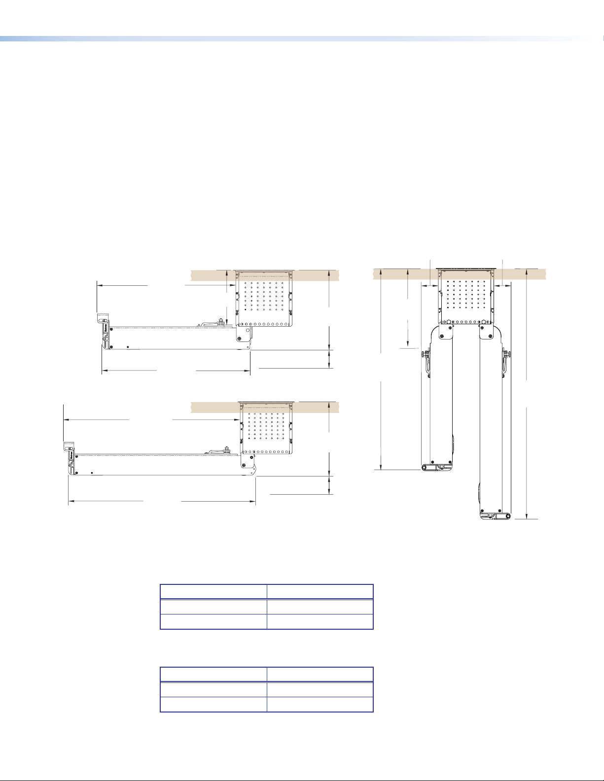
CC300, CC600, CC800 Enclosure Clearances
The following diagrams show the clearance dimensions required for mounting a retractor
system in a CC300, CC600, or CC800 enclosure.
15.7"
(39.9 cm)
See
Table A
9.0"
(22.9 cm)
See
Table B
1.9" (4.8 cm)
1.9" (4.8 cm)
21.7"
(55.0 cm)
16.7"
(42.5 cm)
3.0"
(7.6 cm)
(22.9 cm)
9.0"
23.3"
(59.2 cm)
29.3"
(74.4 cm)
3.0"
(7.6 cm)
23.0"
(58.5 cm)
Horizontal Mounting Clearance
CC300/600/800
XL Models
XL Models
Vertical Mounting Clearance
CC300/600/800
Figure 5. Vertical and Horizontal Clearance Requirements (CC 800 shown)
Enclosure Model Dimension
CC 200 6.2 inches (15.8 cm)
CC 300/600/800 6.4 inches (16.3 cm)
Table A. Vertical Dimension from Table Top To Pigtail
(Horizonal Mounting)
Enclosure Model Dimension
CC 200 9.5 inches (24.1 cm)
CC 300/600/800 9.5 inches (24.1 cm)
Table B. Vertical Dimension from Table Top To Pigtail
(Vertical Mounting)
Cable Retraction System • Before Getting Started 6
Page 13

TLP 350CV, TLP 710CV, TLE 350, TLE 710 Enclosure Clearances
The following diagrams show the clearance dimensions required for mounting a retractor
system in a TouchLink (TLP 350CV and TLP 710CV only) or the TLE series enclosures.
1.9" (4.8 cm)
15.7"
(39.9 cm)
See
Ta ble A
10.0"
(25.4 cm)
See
Table B
1.9" (4.8 cm)
21.7"
(55.0 cm)
23.0"
(58.5 cm)
16.7"
(42.5 cm)
3.0"
(7.6 cm)
3.0"
(7.6 cm)
XL Models
Horizontal Mounting Clearance
TLP 350CV/710CV TLE 350/710
10.0"
(25.4 cm)
24.3"
(61.7 cm)
XL Models
Vertical Mounting Clearance
TLP 350CV/710CV TLE 350/710
30.3"
(77.0 cm)
Figure 6. Vertical and Horizontal Clearance Requirements, TLP 350CV, TLP
710CV, TLE 350, and TLE 710
Retractor installation into the TLP and TLE enclosures is identical to the standard Cable
Cubby enclosures. The enclosures are one inch longer than the CC300/600/800
enclosures, but otherwise the dimensions are the same.
NOTE: Angular mounting requires an additional inch of floor clearance compared to
the Cable Cubby enclosures.
Enclosure Model Dimension
TLP/TLE 7.4 inches (18.8 cm)
Table A. Vertical Dimension from Table Top To Pigtail
(Horizonal Mounting)
Enclosure Model Dimension
TLP/TLE 10.5 inches (29.2 cm)
Table B. Vertical Dimension from Table Top To Pigtail
(Vertical Mounting)
Cable Retraction System • Before Getting Started 7
Page 14

All Installations (Except Drop-in)
Horizontal Mounting: Be certain the horizontal mounting bracket can be fastened
under the table or on a table support without bending the pulley system or forcing it from
perpendicular with the enclosure (see figure 7, “Top View”).
Vertical Mounting: Ensure the retraction system will hang freely without touching the
floor and is not obstructed by anything under the table (see CC300, CC600, CC800
Enclosure Clearances on page6 and TLP 350CV, TLP 710CV, TLE 350, TLE 710
Enclosure Clearances on page7).
Angular Mounting (XL models only): For installations where the tabletop is less than
30inches from the floor, the XL retractor system is too long for vertical mounting and there
may not be adequate under-table clearance for horizontal mounting. An additional mounting
hole has been provided for these installations that allow the retractor system to install at an
angle providing extra floor clearance (see figure 7, right).
Horizontal
Bracket
CC800
CC800
1.9"
(4.7 cm)
UNSWITCHED
100-240V/ 5AMAX
UNSWITCHED
ACTIVITY
USP HUB4 AAP
100-240V/ 5AMAX
10.6"
(27.0 cm)
Top View
26.6"
(70.1 cm)
29.3"
28.0"
(71.1 cm)
30
For minimum table height
requirements of 28 inches
(71 cm) specified by ADA
Section 4.32.
(74.4 cm)
Floor
Figure 7. Horizontal Bracket (Top View) and XL Models Vertical Clearance
Cable Retraction System • Before Getting Started 8
Page 15

Prepare the Cable Cubby Enclosure
The retraction system must be mounted on either
DANGER: SEVERE ELECTRICAL SHOCK. Remove all power from the Cable
Cubby enclosure before beginning a retraction system installation.
All Installations
By now you should be certain the retraction system has adequate under-table clearance
for installation and that proper legroom will be provided to avoid accidental contact with the
system. You should have the required accessories for mounting the retraction system along
with the necessary AAPs and AAP brackets to reconfigure the enclosure.
The retraction system requires two adjacent AAP spaces and must be installed on one side
of the enclosure or the other with the cable release buttons against the enclosure side walls
(see figure8). Filler modules, when used, take up the same space as one retractor. Where
the retraction system is installed in the enclosure is based on under-table clearance, the
mounting orientation of the retractors, and operation preferences.
Install or reconfigure the power module and AAP modules and brackets before beginning
the installation of the retraction system.
Retrofit Installations
Prepare the AAP spaces for the retraction system ensuring sufficient under-table clearance
for the retraction system.
Relocate, remove, or replace existing AAPs and reconfigure associated AAP brackets to
make room for the retraction system.
side of the enclosure with the cable release buttons
CC 800 shown
against the enclosure side walls.
Filler modules
(part #70-678-08)
take up the same
space as one retractor.
Retractors take
two AAP spaces.
UNSWITCHED
100-240V/ 5AMAX
UNSWITCHED
ACTIVITY
USP HUB4 AAP
100-240V/ 5AMAX
Check for adequate cable
clearance inside the
Cable Cubby enclosure.
Figure 8. Retraction System AAP locations
Cable Retraction System • Before Getting Started 9
Page 16
Prepare the Retractors
Remove two enclosure screws
(front and back) from this position
for horizontal or angular mounting.
Cable Stop Assembly
Enclosure
Each retractor is delivered ready to mount vertically. No further modifications are required.
See CC300, CC600, CC800, TLE, TLP Installation on page 14 for vertical installation
details.
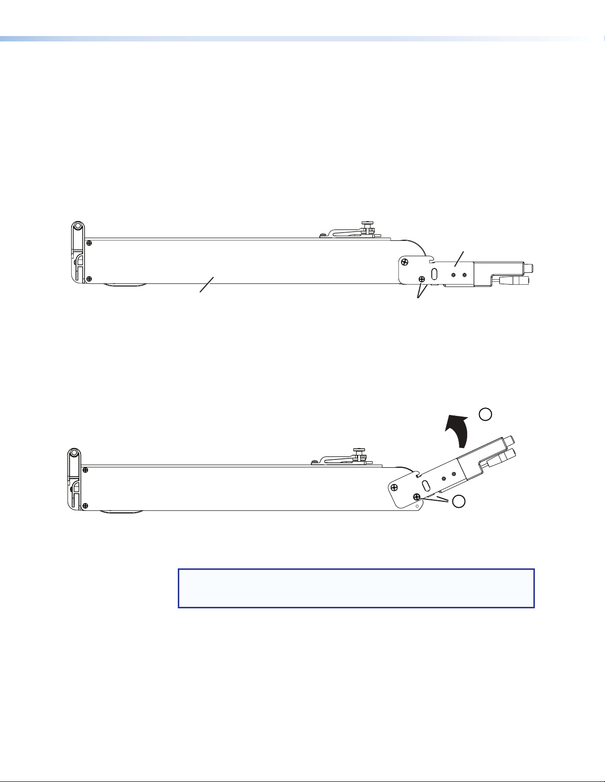
Horizontal or Angular Mounting:
To mount the retractors horizontally or at an angle, remove the two enclosure screws
from the retractor (see figure 9).
For horizontal mounting proceed to the “Installation” section beginning on page 11.
For angular mounting, see below.
Cable Stop Assembly
Enclosure
Remove two enclosure screws
(front and back) from this position
for horizontal or angular mounting.
Figure 9. Remove Enclosure Screws (Horizontal or Angular Mounting Only)
Angular Mounting:
1. To prepare an XL retractor for angular mounting move the cable stop assembly upward
as shown until the mounting hole is visible.
Move cable stop assembly
1
upward until the angular
mounting hole is visible.
Install two enclosure screws
2
(front and back) in angular
mounting location.
Figure 10. Install Angular Mounting Enclosure Screws
2. Reinstall the two screws removed in the preparation above.
NOTE: For Cable Cubby 200 installations, mount the retractor onto the CC 200
mounting bracket before installing in the enclosure (see CC200 Bracket and
Retractor Mounting on page13).
Cable Retraction System • Before Getting Started 10
Page 17

Installation
This section provides details of the retractor system installation, cable connection, and
verification of operation.
• Cable Cubby 200
• CC300, CC600, CC800, TLE, TLP Installation
• Horizontal Bracket Mounting
• Locking Screw (Optional)
• Alternative Solutions
• Laptop Power
• Connect the Cables
• Verify Cable Release Operation
By now you should have determined there is adequate under-table clearance, have all the
required accessories for installation, the enclosure should be prepared, and the retractor
system properly configured.
Cable Retraction System • Installation 11
Page 18

Cable Cubby 200
10.7" (27.2 cm)
The CC200 Mounting Bracket, part number 70-678-10,
allows one or two retractors (standard or XL) to be installed in
a CableCubby200 enclosure. The bracket kit adapts an AAP
opening for retraction system mounting similar to other Cable
Cubby enclosures.
Before installing the adapter, be certain there is adequate space
under the table for the retraction system with the attached
bracket.
NOTE: To prevent objects from impeding cable retraction,
ensure at least 3 inches of clearance from the exposed
cable side of the retractor enclosure.
CC 200 Mounting
Bracket Kit
Determine the retractor mounting orientation: horizontal, vertical, or angular (see Planning
on page4).
0.3" (7.6 mm)
2.0" (5.0 cm)
(x4)
27.5"
(69.9 cm)
XL Models
30
CC 200
Vertical Mounting Clearance
Standard Models
CC 200 Bracket
23.3" (59.1 cm)
3.0"
(7.6 cm)
21.8" (55.3 cm)
15.7" (39.9 cm)
CC 200 Bracket
8.9" (22.6 cm)
3.0" (7.6 cm)
Standard Models
8.9" (22.6 cm)
Figure 11. CC 200 mounting dimensions
3.0" (7.6 cm)
CC200 Horizontal Mounting Clearance
XL Models
Cable Retraction System • Installation 12
Page 19

CC200 Bracket and Retractor Mounting
1. Using the supplied mounting bolt (1/4-20 x 3 inch), mount the CC200 bracket to the
retractor as shown.
NOTE: If only one retractor is mounted, use a filler module (part number
70-678-08) in place of the second retractor.
Once the retractor is mounted to the bracket, the assembly may be installed.
2. The cable stops and connectors may be too large to fit through the AAP opening at the
same time as the retractor. Pull a short amount of cable out of the retractor and push it
through the AAP opening prior to installing the bracket and retractor assembly.
3
Mounting Screw
w / Washer (4 plcs)
2
CC 200
Bracket
Bracket and
Retractor Assembly
1
Mounting Bolt
and Nut
Figure 12. Install the Bracket and Retractor Assembly
3. Press the bracket and retractor assembly against the bottom of the enclosure, lining up
the bracket holes with the AAP mounting holes on the enclosure. Fasten from the top
using the four supplied screws.
4. See Locking Screw (Optional) on page17 for final installation instructions.
Cable Retraction System • Installation 13
Page 20
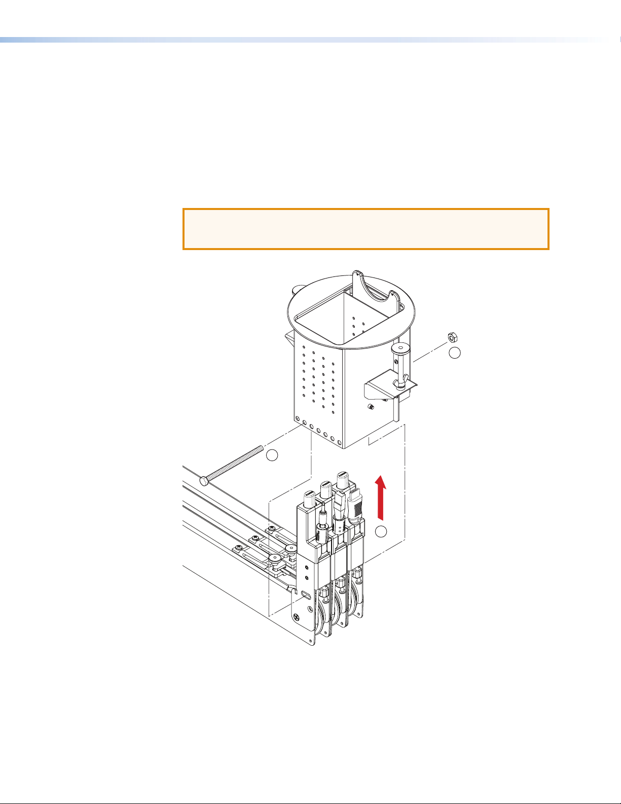
CC300, CC600, CC800, TLE, TLP Installation
The enclosure must be installed and properly configured before beginning the retraction
system installation.
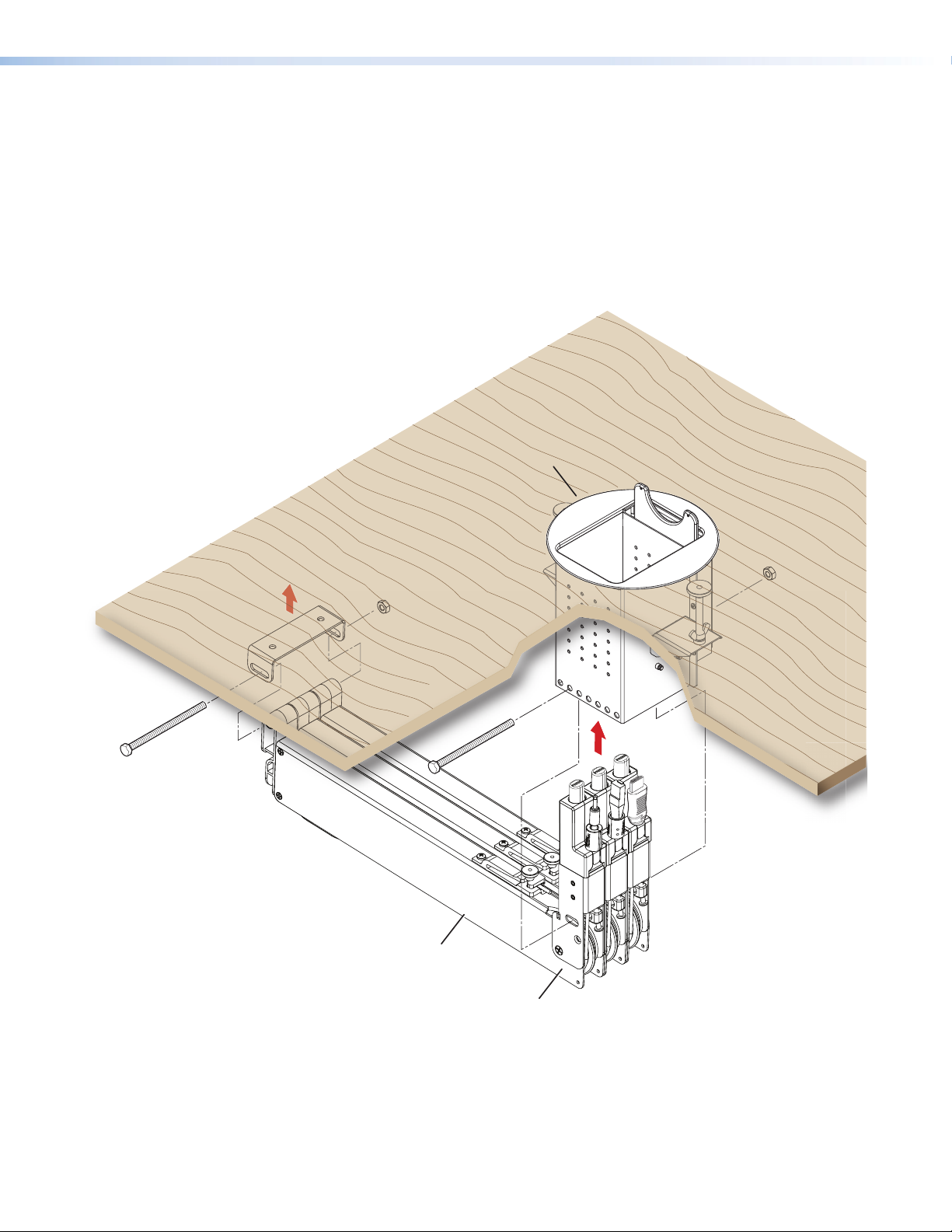
1. With the cable release buttons against the enclosure wall, install the retraction system
by pushing the system up and into the enclosure (see figure 13).
2. With the retraction system against the sidewall, press the mounting bolt through the
second hole from the edge of the Cable Cubby enclosure, through the retraction
system, then out the other side of the enclosure.
3. Thread the nut on the bolt and tighten.
ATTENTION: Do not overtighten the enclosure mounting bolt. It only needs
to be snug. Overtightening could deform the retractor housing and cause
misalignment of the pulley wheels resulting in malfunction.
3
2
1
Figure 13. Retraction System Installation
4. Connect the retraction system cables and other AAP cables (if installed).
5. If horizontally mounting the retractors, proceed to Horizontal Bracket Mounting on
page15.
For vertical and angular mounting, see Locking Screw (Optional) on page17 for
final installation details.
Cable Retraction System • Installation 14
Page 21

Horizontal Bracket Mounting
Top View
For horizontal mounting, the horizontal mounting bracket (part number 70-678-00) must be
used. The slotted holes in the mounting bracket allow for tolerance in placing the bracket.
To ensure accurate bracket location, follow these procedures:
1. Attach the horizontal mounting bracket to the retractor end caps using the provided bolt
and nut.
TIP: Hand tighten the nut only enough to keep the bracket from easily moving.
The bolt and nut will be removed later.
Horizontal Bracket
Mounting Holes
Slotted Hole
Horizontal Mounting
Bolt
End Caps
Figure 14. Attach Horizontal Bracket to End Caps
2. Raise the retraction system with attached bracket to the desired mounting location.
NOTE: Be certain the system is perpendicular to the enclosure to prevent
binding of the pulley system.
UNSWITCHED
100-240V/ 5AMAX
UNSWITCHED
100-240V/ 5AMAX
USP HUB4 AAP
CC800
ACTIVITY
Horizontal
Bracket
Figure 15. Align Retraction System Perpendicular to Cable Cubby Enclosure
Cable Retraction System • Installation 15
Page 22

3. Ensure the bracket is flush with the surface and trace a line around the bracket
perimeter.
Trace Around
Bracket Perimeter
Figure 16. Mark Bracket Location
4. Lower the assembly and remove the horizontal bracket from the retractors.
5. Position the bracket inside the lines drawn in step 3 and fasten with the supplied
screws.
ATTENTION: Ensure the supplied screws do not pierce through the top of the
table. If necessary, use appropriate screws based on the table material and
thickness.
5
5
8
7
6
Figure 17. Position Bracket and Mount
6. Raise the retractor system up into the installed bracket.
7. Run the bolt through the bracket and end caps.
8. Secure the bolt with the nut supplied in step 1.
ATTENTION: Do not overtighten the horizontal mounting nut. It only needs to
be snug. Overtightening could deform the end caps and cause misalignment
of the system resulting in poor cable extension and retraction.
Cable Retraction System • Installation 16
Page 23

Locking Screw (Optional)
w (1 each).
If the retraction system is mounted next to an unused location in the Cable Cubby
enclosure, a locking screw is provided to prevent the retractors from rotating on their
mounting bolt during operation.
If needed, tighten the locking screws to prevent movement of the retractor. There is one
locking screw for each retractor.
NOTE: Do not overtighten. The locking screw only needs to be snug.
Tighten locking
scre
Locking
Screw
Figure 18. Locking Screws
Cable Retraction System • Installation 17
Page 24

Alternative Solutions
Drop-in Installations
For installations with limited under-table access, the retractors must be installed before
dropping the enclosure into the table. All drop-in installations must be mounted vertically or
using angular mounting.
1. For retrofit installations, remove the Cable Cubby enclosure from the furniture.
For new installations follow the Cable Cubby enclosure preparation instructions but
do not mount the enclosure.
2. Install the retraction system in the enclosure following the installation instructions (see
CC300, CC600, CC800, TLE, TLP Installation on page14) and locking screw
instructions (see Locking Screw (Optional) on page17).
3. Once the retraction system is installed, lower the
enclosure and retraction system into the cutout ensuring
that kinking or bending of the cables is prevented.
If the bottom of the retractors will not be accessible,
connect the pigtails before lowering the system.
4. After the enclosure has been dropped into the opening,
lift it just enough to allow the two screw clamps to be
installed.
NOTE: Connect all cables before lowering the enclosure into the cutout.
Screw Clamp
(both sides)
NOTE: In drop-in type installations, it is not
possible to adjust the screw clamps for an
exact fit and will take some trial and error
to adjust it for the tightest fit.
Figure 19. Drop-in Installation
Cable Retraction System • Installation 18
Page 25

Laptop Power
1.4"
(35.56 mm)
0.0"
(7.5 mm)
DC Power Cable
The DC power retractor provides a connection for a laptop on the tabletop to a compatible
laptop power supply (not supplied) under the furniture. Installation of the retractor is
identical to other retractors.
The cable has a female connector under the furniture (b) for connection to a laptop
power supply(a), and male connector on the topside (c) of the table for connection to a
compatible laptop.
ATTENTION:
• Use only the power supply recommended by the manufacturer of
the laptop.
• The cable connectors may not be compatible with all models
of Dell and HP laptop computers and power supplies. See
www.extron.com for a current compatibility list.
DC Power
3
Connector
Laptop
(not supplied)
1
Power Supply
(not supplied)
2
Under-table
Connector
Figure 20. DC Power Retractor Connection
Under-furniture space for the retractor and power must be available for the OEM laptop
power supply. The power supply module should be safely located and supply leads should
be dressed to avoid entanglements and accidental contact.
The power supply (a) must be compatible with both the laptop power requirements and the
female connector (b) on the under-table end of the retractor cable.
The DC power connector (c) must be compatible with the laptop power connection.
Three labels (Dell, HP, and blank-printable) are provided for the
topside connector to identify the laptop it is compatible with.
Affix the appropriate label as shown at right.
Cable Retraction System • Installation 19
Page 26

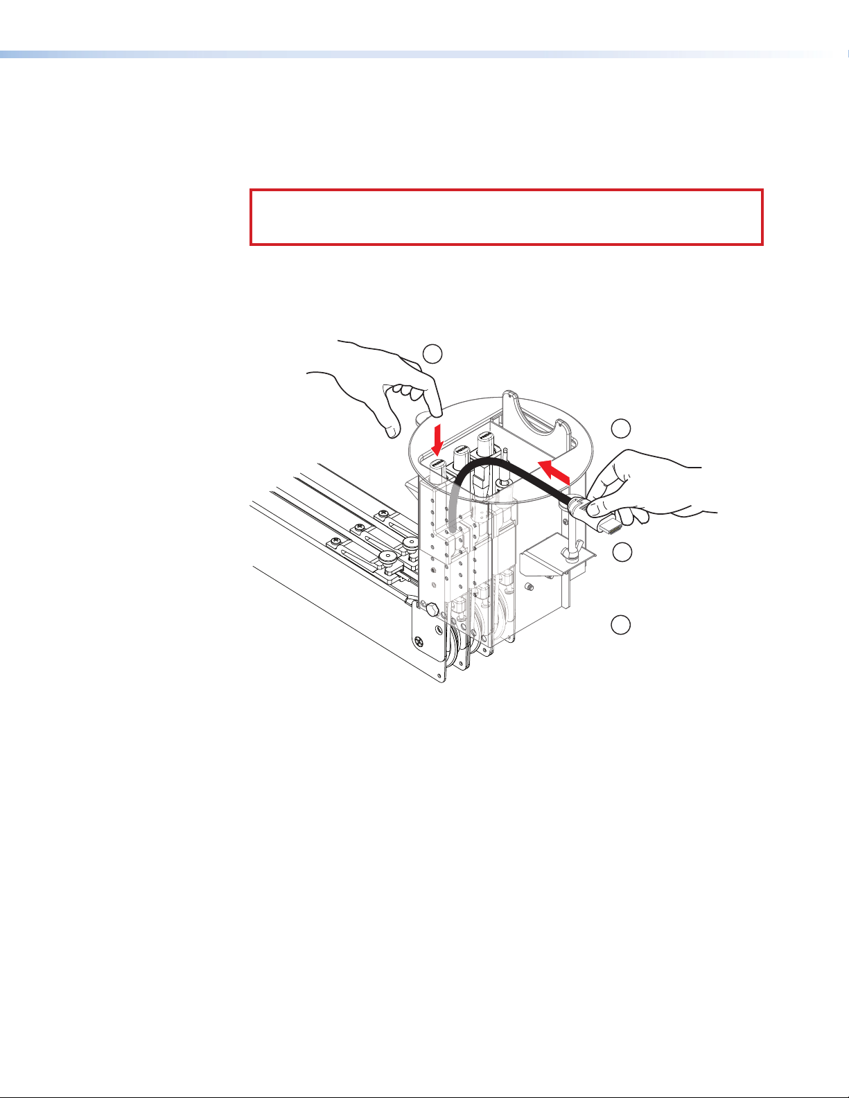
Connect the Cables
Connect the under-enclosure cables to the proper device.
If additional cable length is needed use Extron cable as required.
Excess cabling may cause clearance issues. Use wire ties to secure under-table cabling to
prevent accidental contact or entanglement with users.
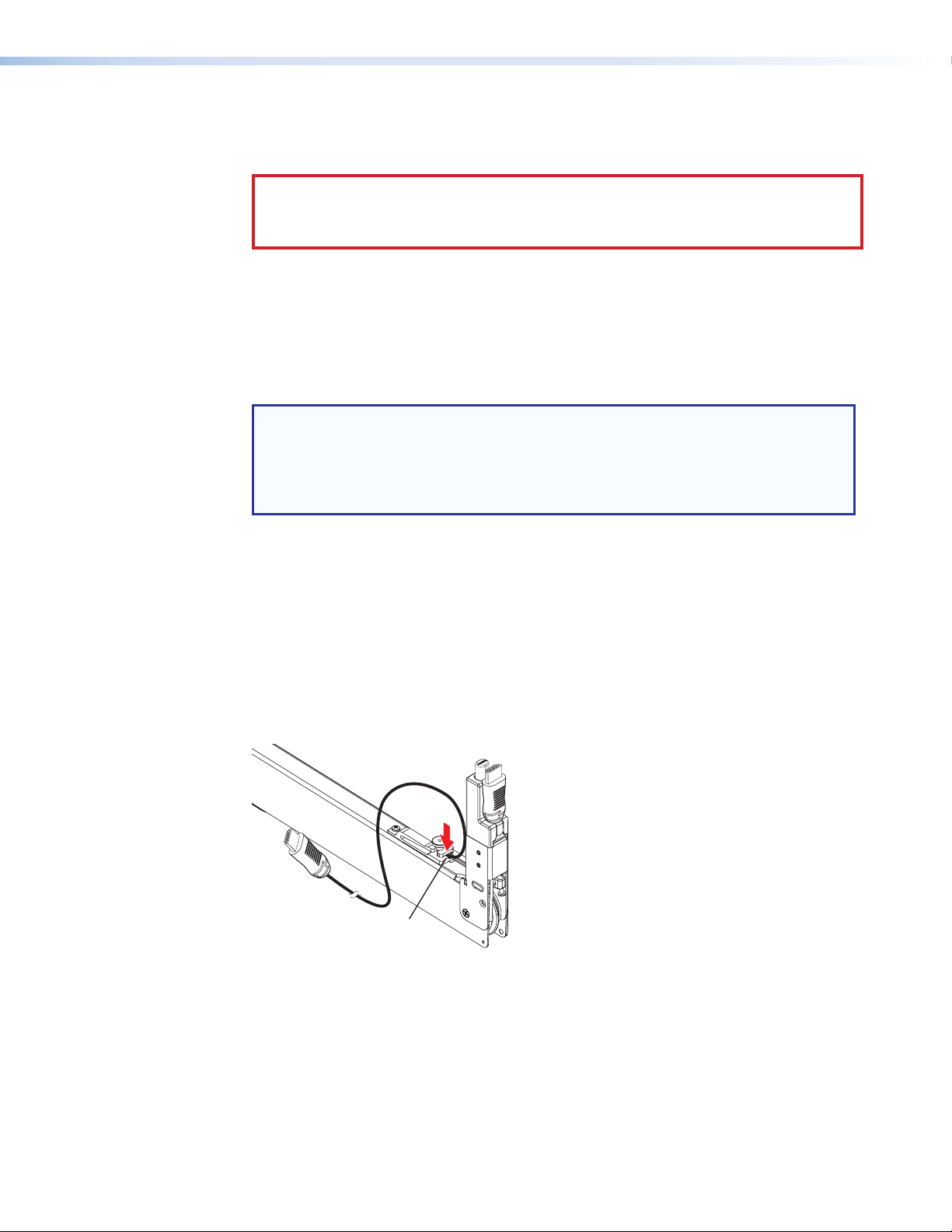
Verify Cable Release Operation
After installation, check the operation of the cable release assembly. Pull a length of cable
from the system. The cable release button stops the cable from retracting back into the
system when pulling ceases.
Make certain the cable pulls freely without jerking or requiring excessive force. If it does,
check under the enclosure to determine if something has fallen into the retraction system
to cause tangling of the cable or is jamming the pulley
system. Also be certain the cable is properly routed
around the pulleys (see figure 22 on page 20).
Release the cable. Hold the connector and press the
release button. When retracting, hold the cable end
as the release button is pressed. Restrict the cable
retraction to a slow, controlled motion.
Ensure the cable retracts completely into the system.
The stop collar (or connector if there is no stop collar)
will rest on the seat of the cable stop assembly, stopping
cable travel. If it does not, proceed to Pulley System
Adjustment on page 23.
Cable Release
Button
Cable Release
Assembly
Stop collar
seated.
Cable Retraction System • Installation 20
Page 27

Operation
This section provides details of the retractor system operation.
• Extend a Cable
• Retract a Cable
Once installed, the retractors are ready for operation.
CAUTION:
• Do not operate a retractor until it is installed.
• When retracting, hold the cable with one hand and press the release button with
• Retraction should be a slow, controlled motion.
• Keep hands away from moving parts.
the other.
Extend a Cable
To connect a cable, grip it by the connector and pull enough cable from the retractor to
connect to the device. There is no need to press the cable release button when extending
a cable. When you stop pulling the cable, the cable release assembly will fix the length
automatically.
Cable Retraction System • Operation 21
Page 28
Retract a Cable
1. Disconnect the cable from the device and with one hand hold it firmly by the connector
to keep the cable taught.
2. With your other hand, press and hold the cable release button.
CAUTION: Use one hand to control the cable as it retracts. A cable allowed to
retract too quickly and without control can cause possible injury to the user or
damage the furniture surface, Cable Cubby, and nearby items.
3. With one hand pressing the release button, continue to hold the cable with the other
hand and allow it to slowly be pulled back into the retractor.
4. When the stop collar (or connector if the cable does not have a stop collar) is seated
against the cable release assembly, release the cable and button.
Press and hold the
2
cable release button.
Hold the cable taught
1
by the connector.
Slowly allow the cable
3
to be pulled until the
stop collar (or connector)
seats against the cable
release assembly.
Release the cable
4
and button.
22
Figure 21. Cable Retraction
Cable Retraction System • Operation 22
Page 29

Maintenance and Adjustments
• Pulley System Adjustment
• Removing and Replacing the System
• Expand the Cable Retraction System
• Add a Cable Retraction System
ATTENTION:
• Each Extron retractor model is designed with custom-made cable and a unique matching spring that work
together to maintain cable signal integrity and preserve consistent cable retraction pull force over the life of
the product. Alterations to the retractor will cause premature failure of the retractor system and cables.
• Modifications to the Retractor System are prohibited and will void the Extron warranty for this product.
Consult your Sales representative for more information.
Pulley System Adjustment
The tension on the cable that provides constant force during cable extension and retraction
is maintained by proper adjustment of the pulley system. Too little tension and the cable will
have slack or may slip out of the pulley tracks, and will not retract properly.
To Adjust the Pulley System:
1. Before beginning pulley system adjustments, ensure the cable routing around the pulley
system is correct (see below) and the cable is completely retracted into the enclosure.
Cables should be in the correct
pulley track, taught, and parallel
to each other.
Figure 22. Cable Routing
Cable Retraction System • Maintenance and Adjustments 23
Page 30

2. Hold the cable to prevent movement.
Anaheim, CA USA
www.extron.com
Cable Retractable System
ARNING!: When retracting, hold the cable end as
the release button is pressed. Restrict
the retraction to a slow, controlled motion.
Keep hands and fingers away from
moving parts.
Do not operate retractor until installed.
Cable Tension Adjustment
For optimum performance, proper cable tension must be
maintained. Follow the steps below or refer to the Cable
Retractable System User Guide for procedures.
1. Hold the cable to prevent movement.
2. Loosen thumbwheel nut on cable retainer.
3. Adjust cable to align tension pulley screw to this hole.
4. When tension is correct, re-tighten the thumbnut to
secure the cable.
Adjust.
Adjust.
4
4
Retainer Clip
Retainer Clip
Loosen thumbwheel
Loosen thumbwheel
3
3
nut.
nut.
Align pulley screw.
Align pulley screw.
Figure 23. Pulley System Adjustment
Hold cable.
Hold cable.
2
2
1
1
Cable stop collar
Cable stop collar
(or connector on
(or connector on
some models) must
some models) must
be seated.
be seated.
3. Loosen the thumbwheel nut on the retainer clip until the cable can be moved. Do not
allow it complete freedom of movement.
4. Adjust the cable to align the bottom pulley screw with the alignment hole on the
enclosure (designated c on the product label in figure24).
24
Alignment
c
Hole
Alignment Hole (pulley screw visible)
The cable and spring assembly have been
tested and optimized for this model.
Contact Extron Electronics for modifications
or repairs.
NOTE: To prevent objects from impeding
cable retraction, ensure at least
three inches of clearance from the
exposed cable side of the enclosure.
W
Figure 24. Product Label on Retractor
5. Hand tighten the thumbwheel nut on the retainer clip to secure the cable.
Cable Retraction System • Maintenance and Adjustments 24
Page 31

Removing and Replacing the System
To Remove the System:
DANGER: Ensure that AC power is disconnected before servicing the system.
1. Remove both ends of all retractor cables from connected devices.
NOTE: Drop-in installations require removal of the enclosure and retraction
system at the same time.
2. If necessary, loosen the locking screw on all retractors. If the system is mounted
vertically, proceed to step 6.
Loosen locking
screw (1 ea).
Figure 25. Loosen Locking Screws
25
3. Hold or otherwise support the cable retraction system near the horizontal bracket.
4. Remove the nut and slide the bolt from the horizontal mounting bracket.
CAUTION: All cable retractors attached to the horizontal mounting bracket will
drop when the bolt is removed.
Remove bolt.
4
Support the
3
retractor system.
Figure 26. Remove Horizontal Mounting Bolt
Cable Retraction System • Maintenance and Adjustments 25
Page 32

5. Slowly lower the system and allow it to hang vertically. If the system was mounted
vertically, it is already in this position.
6. Make certain the retractors are supported so they will not drop unexpectedly.
CAUTION: All retractors attached to the enclosure mounting bolt will drop when
the enclosure mounting bolt is removed.
7. Remove the enclosure mounting bolt. The retraction system is now detached from the
Cable Cubby.
Remove enclosure
7
mounting bolt.
Slide system
8
down and out.
Support the
6
retraction system.
Figure 27. Removing the Cable Retraction System
26
8. Slide the system down and out to remove it from the Cable Cubby.
To Replace the System:
Reverse the previous steps making certain the system is correctly oriented to the Cable
Cubby enclosure.
Cable Retraction System • Maintenance and Adjustments 26
Page 33

Expand the Cable Retraction System
Up to three retractors on each side, six total, (two total for the Cable Cubby 200), can
be mounted in a retraction system installation. If fewer than the maximum are installed
and additional retractors are desired, remove the filler module and replace it with the new
retractor (see Removing and Replacing the System on page25).
Filler
Module
Figure 28. Two Retractors in Cable Cubby Enclosure
27
Cable Retraction System • Maintenance and Adjustments 27
Page 34

Add a Cable Retraction System
The retraction system must be mounted on either
Depending upon the Cable Cubby enclosure, an additional retraction system with up to
three more retractors may be installed. As in the initial retraction system installation, existing
AAPs and their brackets may need to be relocated, removed, or replaced to allow room for
the additional system. The additional system does not have to mount the same as the first,
but proper under-table clearance for both systems, as well as clearances from each other
must be considered.
Filler modules
(part #70-678-08)
take up the same
space as one retractor.
CC 800 shown
side of the enclosure with the cable release buttons
against the enclosure side walls.
UNSWITCHED
100-240V/ 5AMAX
UNSWITCHED
ACTIVITY
USP HUB4 AAP
100-240V/ 5AMAX
Check for adequate cable
Retractors take
two AAP spaces.
clearance inside the
Cable Cubby enclosure.
Figure 29. Add a Retraction System
28
No matter which mounting method used, adequate space must be available inside the
Cable Cubby enclosures for the addititonal cables.
As shown in a typical horizontal mounting installation in figure 30, the second retraction
system will extend the opposite direction as the first.
UNSWITCHED
100-240V/ 5AMAX
UNSWITCHED
ACTIVITY
USP HUB4 AAP
100-240V/ 5AMAX
Existing System Additional System
CC800
Figure 30. Two Retraction Systems (Horizontal Mount)
Cable Retraction System • Maintenance and Adjustments 28
Page 35

Reference
Information
• Cable Retraction System Part Numbers
• Optional Accessories
Cable Retraction System Part Numbers
Retractors are available in versions to support most AV and data signal types including
VGA, Network, PC Audio, USB, DisplayPort, HDMI, and others. Each standard retractor
provides cable that extends up to 3 feet (90cm) from the enclosure. A 6 foot (1.8 m) pigtail
is provided on the input side of the retractor for connection to under-table electronics, floor
boxes, or an Extron AVTrac® floor mounted raceway system.
XL retractors extend up to 5 feet (152cm) from the enclosure and provide a 4 foot (1.2 m)
pigtail.
See the website at www.extron.com for the complete line of the Cable RetractionSystem
for Cable Cubby® Enclosures and Extended Length Cable Retraction System for
CableCubby® Enclosures.
Optional Accessories
Cable Retraction System, All Systems Part number
Retractor Mounting Kit for Horizontal Mounting 70-678-00
Retractor Filler Module 70-678-08
Cable Cubby 200 Mounting Bracket Kit 70-678-10
Cable Retraction System • Reference Information 29
Page 36

Extron Warranty
Extron Electronics warrants this product against defects in materials and workmanship for a period of three years
from the date of purchase. In the event of malfunction during the warranty period attributable directly to faulty
workmanship and/or materials, Extron Electronics will, at its option, repair or replace said products or components,
to whatever extent it shall deem necessary to restore said product to proper operating condition, provided that it is
returned within the warranty period, with proof of purchase and description of malfunction to:
USA, Canada, South America,
and Central America:
Extron Electronics
1230 South Lewis Street
Anaheim, CA 92805
U.S.A.
Europe and Africa:
Extron Europe
Hanzeboulevard 10
3825 PH Amersfoort
The Netherlands
Japan:
Extron Electronics, Japan
Kyodo Building, 16 Ichibancho
Chiyoda-ku, Tokyo 102-0082
Japan
China:
Extron China
686 Ronghua Road
Songjiang District
Shanghai 201611
China
Asia:
Extron Asia Pte Ltd
135 Joo Seng Road, #04-01
PM Industrial Bldg.
Singapore 368363
Middle East:
Extron Middle East
Dubai Airport Free Zone
F12, PO Box 293666
United Arab Emirates, Dubai
Singapore
This Limited Warranty does not apply if the fault has been caused by misuse, improper handling care, electrical
or mechanical abuse, abnormal operating conditions, or if modifications were made to the product that were not
authorized by Extron.
NOTE: If a product is defective, please call Extron and ask for an Application Engineer to receive an RA (Return
Authorization) number. This will begin the repair process.
USA: 714.491.1500 or 800.633.9876 Europe: 31.33.453.4040
Asia: 65.6383.4400 Japan: 81.3.3511.7655
Units must be returned insured, with shipping charges prepaid. If not insured, you assume the risk of loss or damage
during shipment. Returned units must include the serial number and a description of the problem, as well as the
name of the person to contact in case there are any questions.
Extron Electronics makes no further warranties either expressed or implied with respect to the product and its quality,
performance, merchantability, or fitness for any particular use. In no event will Extron Electronics be liable for direct,
indirect, or consequential damages resulting from any defect in this product even if Extron Electronics has been
advised of such damage.
Please note that laws vary from state to state and country to country, and that some provisions of this warranty may
not apply to you.
Extron Headquarters
+1.800.633.9876 (Inside USA/Canada Only)
Extron USA - West Extron USA - East
+1.714.491.1500 +1.919.850.1000
+1.714.491.1517 FAX +1.919.850.1001 FAX
Extron Europe
+800.3987.6673
(Inside Europe Only)
+31.33.453.4040
+31.33.453.4050 FAX
© 2013 Extron Electronics All rights reserved. www.extron.com
Extron Asia
800.3987.6673
(Inside Asia Only)
+65.6383.4400
+65.6383.4664 FAX
Extron Japan
+81.3.3511.7655
+81.3.3511.7656 FAX
Extron China
+4000. 398766
(Inside China Only)
+86.21.3760.1568
+86.21.3760.1566 FAX
Extron Middle East
+971.4.299.1800
+971.4.299.1880 FAX
Extron Korea
+82.2.3444.1571
+82.2.3444.1575 FAX
Extron India
1800.3070.3777
(Inside India Only)
+91.80.3055.3777
+91.80.3055.3737 FAX
 Loading...