

Page 1
IMPO RTANT:
TRIM
Tip (L)
Tip-Ring-SleeveTip-Sleeve
Go to www.extron.com for the complete
user guide, installation instructions, and
BUC 202 • Setup Guide
specifications before connecting the
product to the power source.
This guide provides instructions for an experienced installer to set up and operate the Extron
BUC 202 two channel unbalanced/balanced audio converter and line driver.
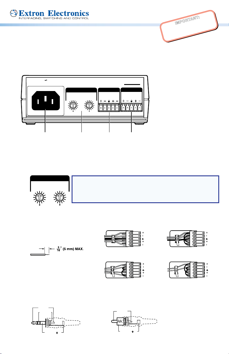
Rear Panel Features and Cabling
100-240V 50/60 Hz
0.2A MAX
TRIM
1
0
-3
3
-6
6
-6
-9
9
-9
-12
-12
12
-15
-15
15
-18
-18
18
-21
-21
21
A
AC power — Connect to standard AC power: 100 to 240 VAC, at 50 or 60 Hz.
A
Trim adjustment (channels 1 and 2) — Adjust the audio input level for the channel using
B
B
INPUTS
1
2
0
-3
3
6
9
12
15
18
21
C
2
BUC 202
OUTPUTS
1
D
2
the 16-position rotary switch. This switch sets the level in 3 dB increments from -21 dB to
+21 dB. The arrow on the shaft indicates the current setting.
1
0
-3
-6
-9
-12
-15
-18
-21
Input connector — This 3.5 mm 5-pole captive screw connector accepts line level
C
-3
3
-6
6
-9
9
-12
12
-15
15
-18
18
-21
21
NOTE: Unity gain (0 dB) for both channels is at the 12 o’clock
2
0
3
6
18
21
(vertical) position with the arrow on the shaft pointing to the 0
position. When the switch is set to the bottom position (indicated
9
12
by a dot) the signal is muted (see Adjusting the Trim).
15
balanced or unbalanced, mono or stereo audio signals (see the illustrations below for
proper wiring).
Do not tin the wires!
Tip
Ring
Sleeves
Tip
Ring
Balanced Stereo Input
Tip
Sleeve
Tip
Sleeve
12
Tip
Ring
Sleeve
Balanced Dual Mono Input
12
Tip
Sleeve
(high impedance)
12
12
Unbalanced Stereo Input
Tip-ring-sleeve and tip-sleeve connections:
Ring (R)
Sleeve ( )
Unbalanced Dual Mono Input
Tip (+)
Sleeve ( )
Page 2
BUC 202 • Setup Guide (Continued)
No Ground Here
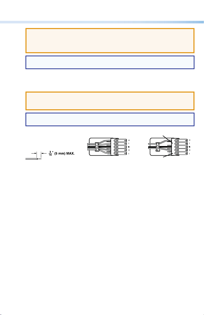
ATTENTION: The length of the exposed wires in the stripping process is critical.
The ideal length is 3/16 inches (5 mm). Any longer and the exposed wires may touch,
causing a short circuit between them. Any shorter and the wires can be easily pulled
out even if tightly fastened by the captive screws.
NOTE: Do not tin the wires. Tinned wires are not as secure in the connector and
could be pulled out.
Output connector — The 3.5 mm 5-pole captive screw connector outputs balanced or
D
unbalanced audio signals (see the illustrations below for proper wiring).
ATTENTION: For unbalanced audio output, connect sleeves to the center ground
pin. DO NOT connect sleeves to the negative (–) contacts. This would create a short
and possibly damage the unit.
NOTE: Do not tin the wires. Tinned wires are not as secure in the connector and
could be pulled out.
Do not tin the wires!
Tip
Ring
Sleeves
Tip
Ring
Balanced Audio Output
12
Tip
Sleeves
Tip
No Ground Here
Unbalanced Audio Output
12
Front Panel
The green power LED on the front panel lights when the BUC 202 is receiving power.
Adjusting the Trim
The BUC 202 can be wired in four different configurations:
• Balanced input to unbalanced output
• Unbalanced input to balanced output
• Balanced input to balanced output
• Unbalanced input to unbalanced output
Follow the steps below to adjust the trim:
1. Disconnect power from all devices.
2. Wire the BUC 202 for either balanced or unbalanced stereo or dual mono audio input.
3. Wire the BUC 202 for either balanced or unbalanced audio output.
4. Set the trim adjustment:
a. Determine the input and output signal types (balanced or unbalanced) and whether it is
consumer or professional audio.
Page 3

Find the trim adjusment setting according to the following table.
Balanced Unbalanced
Consumer
0 dB
-12 dB
0 dB
-12 dB
1
Professional
12 dB
2
0 dB
12 dB
0 dB
Balanced
Unbalanced
Input
Consumer
Professional
Consumer
Professional
Output
1
2
1
2
NOTES:
1
Consumer line level is -10 dBV ≈ -8 dBu.
2
Professional line level is +4 dBu.
b. Use a small screwdriver to turn the appropriate trim adjustment switch to the desired
setting.
5. Reconnect power to all devices to test the audio.
6. If necessary, readjust the trim.
Using the ZipClip™ 200
To attach the BUC 202 to the ZipClip 200 mounting clip:
1. Insert the bottom of the BUC 202 down into the clip, starting with one end.
2. Pivot the other end down and press until the clip snaps into place.
Consumer
6 dB
-6 dB
6 dB
-6 dB
1
Professional
2
18 dB
6 dB
18 dB
6 dB
2
To remove the BUC 202 from the ZipClip:
1. Press the tab on the ZipClip (1).
2. Pivot the BUC 202 and lift it out of the ZipClip (2).
To fasten the tie wraps for cable strain relief:
1. Attach the BUC 202 to the ZipClip 200
mounting clip as descibed previously.
2. Fasten loose cables to the ZipClip base.
a. Insert the tie wraps (“zip ties”)
along the notches on the side of
the BUC 202 and through the tie
wrap anchor points on the
ZipClip, then around the cables.
b. Connect and pull the tie wraps until
they are secure. Do not overtighten.
BUC 202
1
100-240V 50/60 Hz
0.2A MAX
TRIM
1
-3
-6
0
-9
3
-12
6
-15
2
INPUTS
9
-3
-18
-6
0
-9
12
BUC 202
3
-21
-12
15
1
6
18
-15
21
9
9
-18
12
OUTPUTS
12
2
-21
15
15
18
21
1
2
Tie Wrap
Page 4

BUC 202 • Setup Guide (Continued)
2
Mounting to Rack Rails Using a ZipClip
1. Fasten the ZipClip 200 mounting
clip to a rack rail using two rack
screws as shown in the
diagram on the right.
2. Insert the BUC 202 into the ZipClip
as described previously and press to
snap it into place.
Mounting to a Rack Shelf
The BUC 202 is one-quarter rack width wide.
Up to four BUC 202 units can be mounted side
by side directly onto a rack shelf.
1. Align the threaded holes in the bottom
of the BUC 202 with the holes in an Extron
rack shelf (1). Fasten the BUC 202 to the
shelf with two 4-40 x 3/16 inch screws as
shown on the right.
2. Bolt the rack shelf to the rack (2).
Under-Furniture Mounting
Side of Rack
BUC 202
z
H
0
X
50/6
MA
240V
0.2A
100-
Inside of Rack
BUC 202
1
(2) 4-40 x 3/16"
Screws
Rack Mounted
ZipClip 200
B
UC 202
C 202
S
BU
2
UTPUT
O
1
2
UTS
INP
1
TRIM
2
6
9
3
0
12
3
15
TRIM
6
18
1
9
2
12
1
6
9
5
-
3
21
1
2
-
18
0
-
1
-
3
15
8
6
1
1
9
2
12
-
21
15
-
18
-
-
Back of
Rack
RSB 123
Rack Shelf
NOTE: The ZipClip is shipped with
a set of four wood screws.
1. Attach the ZipClip to the furniture
using two or more wood screws as
shown on the right (1). Make sure the clip
is oriented with the appropriate side facing
the mounting surface and with the tab
accessible from the front of the furniture.
2. Insert the BUC 202 into the ZipClip as
described previously and press to snap it
into place (2).
Extron Headquarters
+1.800.633.9876 (Inside USA/Canada Only)
Extron Europe
+31.33.453.4040
1
2
Furniture Mounted
Extron Asia
+65.6383.4400
Extron Japan
+81.3.3511.7655
© 2014 Extron Electronics All rights reserved. www.extron.com
Extron China
+86.21.3760.1568
Extron Middle East
+971.4.299.1800
ZipClip 200
-21
18
1
5
21
12
18
-9
15
-
-
2
18
1
-6
-
1
1
5
2
2
1
-
-12
3
1
0
9
1
0
.
2
8
0
0
6
3
A
-2
-9
M
1
4
5
0
1
A
V
-6
X
12
5
-3
0
/6
9
0
0
6
3
Hz
T
2
RIM
1
I
2
N
PU
TS
1
O
2
U
TP
U
TS
BUC
20
2
Extron Korea
+82.2.3444.1571
Extron India
+91.80.3055.3777
Rev. A 03 14
68-2351-50
 Loading...