

Page 1
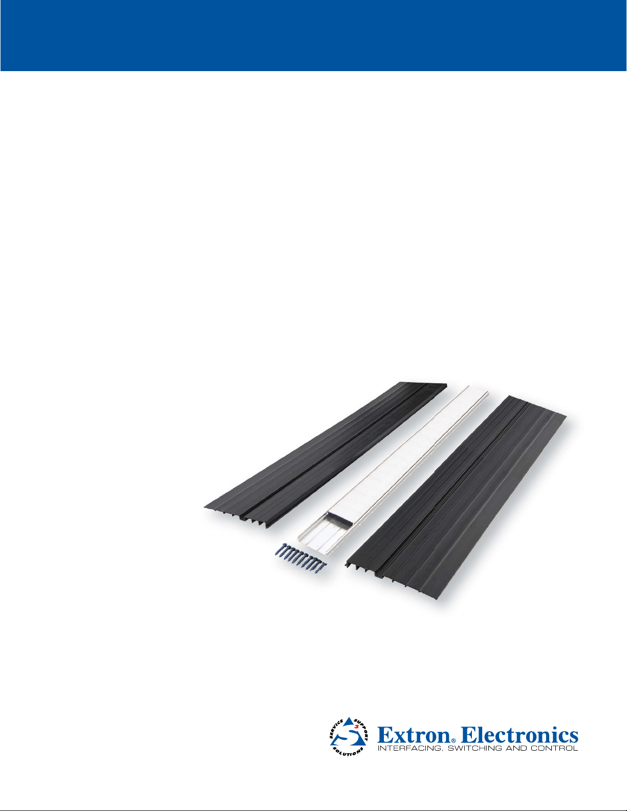
User Guide
Architectural Connectivity
AVTrac
Floor Mount Raceway System
®
Extension Kit
68-1492-01 Rev. D
03 13
Page 2
Safety Instructions
Safety Instructions • English
WARNING: This symbol, D, when used on the product, is intended to
alert the user of the presence of uninsulated dangerous voltage within
the product’s enclosure that may present a risk of electric shock.
ATTENTION: This symbol, I, when used on the product, is intended
to alert the user of important operating and maintenance (servicing)
instructions in the literature provided with the equipment.
For information on safety guidelines, regulatory compliances, EMI/EMF
compatibility, accessibility, and related topics, see the Extron Safety and
Regulatory Compliance Guide, part number 68-290-01, on the Extron
website, www.extron.com.
Instructions de sécurité • Français
avertissement: Ce pictogramme, D, lorsqu’il est utilisé sur le
produit, signale à l’utilisateur la présence à l’intérieur du boîtier
du produit d’une tension électrique dangereuse susceptible de
provoquer un choc électrique.
attention: Ce pictogramme, I, lorsqu’il est utilisé sur le produit,
signale à l’utilisateur des instructions d’utilisation ou de maintenance
importantes qui se trouvent dans la documentation fournie avec le
matériel.
Pour en savoir plus sur les règles de sécurité, la conformité à la
réglementation, la compatibilité EMI/EMF, l’accessibilité, et autres sujets
connexes, lisez les informations de sécurité et de conformité Extron,
réf. 68-290-01, sur le site Extron, www.extron.fr.
Sicherheitsanweisungen • Deutsch
warnung: Dieses Symbol D auf dem Produkt soll den Benutzer
darauf aufmerksam machen, dass im Inneren des Gehäuses dieses
Produktes gefährliche Spannungen herrschen, die nicht isoliert sind
und die einen elektrischen Schlag verursachen können.
Chinese Simplified(简体中文)
警告:D产品上的这个标志意在警告用户该产品机壳内有暴露的危险
电 压 ,有 触 电 危 险 。
注意:I 产品上的这个标志意在提示用户设备随附的用户手册中有
重要的操作和维护(维修)说明。
关于我们产品的安全指南、遵循的规范、
使用的特性等相关内容,敬请访问
安全规范指南,产品编号
68-290-01。
EMI/EMF 的兼容性、无障碍
Extron 网站 www.extron.com,参见 Extron
Chinese Traditional(繁體中文)
警告: D若產品上使用此符號,是為了提醒使用者,產品機殼內存在著
可能會導致觸電之風險的未絕緣危險電壓。
注意I 若產品上使用此符號,是為了提醒使用者。
有關安全性指導方針、法規遵守、EMI/EMF 相容性、存取範圍和相關主題的詳細
資訊,請瀏覽 Extron 網站:www.extron.cn,然後參閱《Extron 安全性與法規
遵守手冊》,準則編號 68-290-01。
Japanese
警告: この記 号 D が製品上に表示されている場合は、筐体内に絶縁されて
いない高電圧が流れ、感電の危険 があることを示しています。
注意: この記号 I が製品上に表示されている場合は、本機の取 扱説明書に記載されて
いる重要な操 作と保 守( 整 備) の指 示につ いてユーザーの注 意を喚起 するものです。
vorsicht: Dieses Symbol I auf dem Produkt soll dem Benutzer in
der im Lieferumfang enthaltenen Dokumentation besonders wichtige
Hinweise zur Bedienung und Wartung (Instandhaltung) geben.
Weitere Informationen über die Sicherheitsrichtlinien, Produkthandhabung,
EMI/EMF-Kompatibilität, Zugänglichkeit und verwandte Themen finden Sie
in den Extron-Richtlinien für Sicherheit und Handhabung (Artikelnummer
68-290-01) auf der Extron-Website, www.extron.de.
Instrucciones de seguridad • Español
aDvertencia: Este símbolo, D, cuando se utiliza en el producto,
avisa al usuario de la presencia de voltaje peligroso sin aislar dentro del
producto, lo que puede representar un riesgo de descarga eléctrica.
atenciÓn: Este símbolo, I, cuando se utiliza en el producto, avisa
al usuario de la presencia de importantes instrucciones de uso y
mantenimiento recogidas en la documentación proporcionada con
el equipo.
Para obtener información sobre directrices de seguridad, cumplimiento
de normativas, compatibilidad electromagnética, accesibilidad y temas
relacionados, consulte la Guía de cumplimiento de normativas y seguridad
de Extron, referencia 68-290-01, en el sitio Web de Extron, www.extron.es.
安全上のご注意、法令遵守、EMI/EMF適合性、その他の関連項目に
つ い て は 、エ クスト ロ ン の ウ ェ ブ サ イト www.extron.jpより
『Extron Safety and Regulatory Compliance Guide』 (P/N 68-290-01) をご覧く
ださい。
Korean
경고: 이 기호 D, 가 제품에 사용될 경우, 제품의 인클로저 내에 있는
접지되지 않은 위험한 전류로 인해 사용자가 감전될 위험이 있음을
경고합니다.
주의: 이 기호 I, 가 제품에 사용될 경우, 장비와 함께 제공된 책자에 나와
있는 주요 운영 및 유지보수(정비) 지침을 경고합니다.
안전 가이드라인, 규제 준수, EMI/EMF 호환성, 접근성, 그리고 관련
항목에 대한 자세한 내용은 Extron 웹 사이트(www.extron.com)의
Extron 안전 및 규제 준수 안내서, 68-290-01 조항을 참조하십시오.
Page 3

FCC Class A Notice
This equipment has been tested and found to comply with the limits for a Class A digital device, pursuant to part
15 of the FCC Rules. Operation is subject to the following two conditions:
1. This device may not cause harmful interference.
2. This device must accept any interference received, including interference that may cause undesired
operation.
The Class A limits are designed to provide reasonable protection against harmful interference when the equipment is operated in a commercial environment. This equipment generates, uses, and can radiate radio frequency
energy and, if not installed and used in accordance with the user guide, may cause harmful interference to radio
communications. Operation of this equipment in a residential area is likely to cause harmful interference, in which
case the user will be required to correct the interference at his own expense.
NOTE: This unit was tested with shielded cables on the peripheral devices. Shielded cables must be used
with theunit to ensure compliance with FCC emissions limits.
For more information on safety guidelines, regulatory compliances, EMI/EMF compatibility, accessibility,
and related topics, see the “Extron Safety and Regulatory Compliance Guide” on the Extron website.
Specications Availability
Product specifications are available on the Extron website, www.extron.com.
Copyright
© 2013 Extron Electronics. All rights reserved.
Trademarks
All trademarks mentioned in this guide are the properties of their respective owners.
The following registered trademarks
(R)
, registered service marks
(SM)
, and trademarks
(TM)
are the property of
RGBSystems, Inc. or Extron Electronics:
(®)
Registered Trademarks
AVTrac, Cable Cubby, CrossPoint, eBUS, EDID Manager, EDID Minder, Extron, Flat Field,GlobalViewer, Hideaway, Inline, IP Intercom, IP
Link, Key Minder, LockIt, MediaLink, PoleVault, PURE3, Quantum, SoundField, System Integrator, TouchLink, V-Lock, VersaTools, VNMatrix, VoiceLift, WallVault, WindoWall
(SM)
Registered Service Mark
AAP, AFL (Accu-Rate Frame Lock), ADSP (Advanced Digital Sync Processing), AIS (Advanced Instruction Set), Auto-Image, CDRS (Class D
Ripple Suppression), DDSP (Digital Display Sync Processing), DMI (Dynamic Motion Interpolation), Driver Configurator, DSP Configurator,
DSVP (Digital Sync Validation Processing), FastBite, FOXBOX, IP Intercom HelpDesk, MAAP, MicroDigital, PowerCage, ProDSP, QS-FPC
(QuickSwitch Front Panel Controller), Scope-Trigger, SIS, Simple Instruction Set, Skew-Free, SpeedMount, SpeedNav, SpeedSwitch,
Triple-Action Switching, XTP, XTP Systems, XTRA, ZipCaddy, ZipClip
: S3 Service Support Solutions
Trademarks
(™)
Page 4

Conventions Used in this Guide
In this user guide, the following are used:
WARNING: A warning warns of things or actions that might cause injury, death, or
other severe consequences.
ATTENTION: Attention indicates a potential hazard to equipment or data.
NOTE: A note draws attention to important information.
TIP: A tip provides a suggestion to make working with the application easier.
Page 5

Contents
Specifications Availability ............................ iii
Kit Contents ...................................................
Contents checklist .......................................... 1
Before Getting Started .................................. 2
Tools and Equipment Required
for Installation ................................................ 2
Tools ............................................................ 2
Other Equipment ......................................... 2
Installation ...................................................... 3
Step 1: Track Mounting .................................. 3
New Construction ........................................ 3
Prelaid Carpet .............................................. 3
Step 2: Finishing Up ....................................... 6
Reference Material ........................................ 8
Optional Accessories ..................................... 8
AVTrac Floor System .................................... 8
1
AVTrac Extensions • Contents v
Page 6

AVTrac Extensions • Contentsvi
Page 7

Kit Contents
The AVTrac Extension kit is available as a 4 feet (1.22 meter) extension for the AVTrac system. An optional rubber
strip inlay kit (partnumber 70-670-01) can be purchased separately.
Check contents of each box to ensure all items are present.
Plastic Template (1)
Side Ramp (2)
Installation
Guide
Aluminum
Base Track (1)
Figure 1. Kit Contents
Aluminum
Cover Track (1)
5/32" Masonry Bit (1) and
3/16" Masonry Screws
Contents checklist
4 feet (1.22 m) Aluminum Base Track (1)
4 feet (1.22 m) Aluminum Cover Track (1)
4 feet (1.22 m) Side Ramps (2)
Plastic Wall Base Trim Template (1)
3/16 inches Masonry Screws (10)
5/32 inches Masonry Drill Bit (1)
Installation Guide (1)
NOTE: If you are using the AVTrac extensions with the complete AVTrac system, please
consult the AVTrac User Guide or an Extron Representative for instructions and advice
about compatibility.
AVTrac Extensions • Kit Contents 1
Page 8

Before Getting
Started
Tools and Equipment Required for Installation
Almost everything that you need to install your AVTrac kit has been included. You will need some basic tools and
materials depending on the facility and requirements.
NOTE: All structural steps and electrical installation should be performed by qualied personnel in
accordance with local and national building codes and electrical codes.
Extron recommends the following equipment (not provided) to ensure the AVTrac is properly installed:
Tools
Miter saw with blade for cutting metal
Hand saw for cutting drywall
Utility knives (box cutters)
Power drill
1/4 inches bit for drilling metal
Tin snips (metal shears)
Tools for terminating cables (if required)
Phillips head screw driver
Hex nut driver (1/4 inches and 5/16 inches)
Metal straightedge (for cutting carpet)
Other Equipment
Tape measure
Marker pen
Level
Fish tape (used for pulling cables through cavity walls)
Cable ties
Vacuum cleaner
Carpet glue
Safety goggles
AVTrac Extensions • Before Getting Started2
Page 9

Installation
Step 1: Track Mounting
At this point you must already have checked the contents of the kit and gathered the tools that you will need for
installation.
Before installation, ensure that the Extension Kit matches the AVTrac product to make a proper junction.
WARNING: Existing AVTrac rubber inlay models may be mismatched with the cover track of the extension
kit. This mismatch may present a tripping hazard. Consult an Extron representative for advice.
For further information about using the AVTrac extensions with the complete AVTrac system, please consult the
AVTrac Installation Guide or the Extron Website (www.extron.com) for instructions about installing the electrical
power and AV modules.
1. Whenever possible, completely remove the carpet
from where the track will be laid. If this is not
possible, cut the carpet.
After removing the carpet, make sure that the
concrete base is level and structurally sound. Prior
to installation, leveling and topping may be needed.
Determine whether the installation will be in new
construction, under pre-existing carpet tiles, or
under pre-existing carpet rolls and follow the
appropriate instructions.
New Construction
When AVTrac is being placed in a new building, the
carpet should not be laid until the track has been
installed.
Prelaid Carpet
For installation of AVTrac under prelaid carpet, cut or
peel back the carpet to expose the concrete where
the track and side ramps will be positioned.
NOTE: AVTrac is not designed to be installed
under vinyl composite tile (VCT).
Figure 2. Remove carpet tiles to expose concrete.
AVTrac Extensions • Track Mounting 3
Page 10

2. If the AVTrac will abut the wall, remove the
baseboard from the bottom of the wall and mark the
position of the AVTrac.
3. Using a drill, box cutters, or a saw, cut a hole at the
base of the wall 4 inches W x 1½ inches H (10.2cm
x 3.8cm).
If there is a metal base stud, use a hand saw or tin
snips to cut it at both edges of the hole and bend
it back into the hole so that it lies at on the oor.
Use a le to remove any jagged edges that might
damage cables.
The hole will eventually be covered by the
baseboard, so it does not have to be perfect.
Figure 3. Mark the wall.
4. If necessary, measure and cut the track pieces to
the desired length. The cut must be clean, as it must
abut the existing AVTrac system or the wall.
AVTrac Extensions • Track Mounting4
Figure 4. Cut the cable access hole in the wall.
Figure 5. Cut the aluminum base track.
Page 11

5. Pre-drill mounting holes in the shallow grooves of
Pre-drill holes in
the base track and side ramps using a 1/4 inches bit
for drilling metal (not supplied.)
NOTE: Mounting holes must be a
maximum of 3feet (0.91 m) apart, and
one must be within 6 inches (0.15 m) of
each end of the track.
the shallow groove
in the base track.
Pre-drill holes in
the shallow groove
in the side ramp.
Side Ramp
Base Track
Figure 6. Pre-drill the holes in the track and ramps.
6. If the extension kit is to be used with an existing
AVTrac installation, align the base track so that it
abuts the end of the installed AVTrac.
Mate the tabs in the side ramps with the grooves in
the base track.
ATTENTION: Before using the Extension kit
with an existing AVTrac rubber inlay model,
consult an Extron representative for advice
about compatibility.
7. Using the provided masonry bit, drill 1-1/4 inches
deep pilot holes into the concrete through the
pre-drilled mounting holes in the track and ramps.
Mate side ramp to base track.
Align extension kit
to installed AVTr ac.
Figure 7. Align the base track and mate the side ramps.
Drill 5/32” x 1-1/4” deep hole
into concrete.
Supplied Masonry Screws
8. With the provided masonry screws, secure the track
and ramps to the oor.
Figure 8. Drill into the concrete and secure the track.
Figure 9. Secure the side ramps to the floor.
AVTrac Extensions • Track Mounting 5
Page 12

Step 2: Finishing Up
At this point, the track must already have been secured to the floor.
To complete the installation of the AVTrac, follow these instructions:
1. Lay the cables and power cords at against the
base track. If necessary, feed excess cable back
into the wall.
Snap the cover track onto the base track.
2. Before cutting and gluing the carpet, remove all
dust and debris with a vacuum cleaner.
Cut the carpet or carpet tiles so that they run up
to but do not cover the aluminum track (see the
diagram below).
Figure 10. Lay the cables flat and fit the cover track.
Figure 12. Cover the ramps.
3. Glue or tape the carpet to the oor and side ramps.
Figure 11. Cut the carpet.
Carpet covers ramps
but not track.
Figure 13. Refit the carpet.
6
AVTrac Extensions • Finishing Up
Page 13

4. If the extension kit abuts the wall, use the provided
template to trim the wall base board so that it ts
snugly around the track.
5. Attach the base board to the wall.
Figure 14. Use the template to cut the base board.
6. To insert a carpet inlay, cut a strip of the nished
carpeting and glue or tape it to the cover track
raceway.
For an alternative rubber nish, use the optional
rubber strip inlay kit (partnumber 70-670-01).
Figure 15. Reattach the base board to the wall.
Figure 16. Attach carpet to the track raceway.
AVTrac Extensions • Finishing Up 7
Page 14

Reference Material
Optional Accessories
AVTrac Floor System
To ensure a precise join when this kit is used with another AVTrac product, the two products must be
compatible.
Accessory Part Number
AVTrac 482C Carpet Inlay, No AC
AVTrac 482R Rubber Strip, No AC
AVTrac 482C AC Carpet Inlay, w/AC US, Prewired Conduit
AVTrac 482R AC Rubber Strip, w/AC US, Prewired Conduit
AVTrac Rubber Inlay kit
AVTrac Rough-In Adapter
AVTrac Wall Trim Plate
AVTrac Raceway Transition (Wiremold)
AVTrac AAP Enclosure
AVTrac AC Power Modules, two US outlets
AVTrac AC Power Modules, four US outlets
AVTrac AC Power Modules, one Australian outlet
AVTrac Cable Pass-Through Kit
AVTrac Extra Channel Kit
AVTrac Retrofit Transition Adapter
42-155-00
42-156-00
42-155-24A
42-156-24A
70-670-01
70-781-01
70-782-01
70-783-01
70-801-02
70-799-08
70-799-09
70-799-05
70-714-02
70-671-01
70-679-22
ATTENTION: Before using the Extension kit with an existing AVTrac rubber inlay model, consult an Extron
representative for advice about compatibility.
8
AVTrac Extensions • Reference Material
Page 15

Extron Warranty
Extron Electronics warrants this product against defects in materials and workmanship for a period of three years
from the date of purchase; touchscreen display and overlay components are covered for 1 year. In the event of
malfunction during the warranty period attributable directly to faulty workmanship and/or materials, Extron Electronics
will, at its option, repair or replace said products or components, to whatever extent it shall deem necessary to
restore said product to proper operating condition, provided that it is returned within the warranty period, with proof
of purchase and description of malfunction to:
USA, Canada, South America,
and Central America:
Extron Electronics
1230 South Lewis St.
Anaheim, CA 92805
U.S.A.
Europe, Africa, and the Middle East:
Extron Europe
Hanzeboulevard 10
3825 PH Amersfoort
The Netherlands
Japan:
Extron Electronics, Japan
Kyodo Building, 16 Ichibancho
Chiyoda-ku, Tokyo 102-0082
Japan
China:
Extron China
686 Ronghua Road
Songjiang District
Shanghai 201611
China
Asia:
Extron Asia Pte. Ltd.
135 Joo Seng Road, #04-01
PM Industrial Bldg.
Singapore 368363
Middle East:
Extron Middle East
Dubai Airport Free Zone
F12, PO Box 293666
United Arab Emirates, Dubai
Singapore
This Limited Warranty does not apply if the fault has been caused by misuse, improper handling care, electrical
or mechanical abuse, abnormal operating conditions, or modifications were made to the product that were not
authorized by Extron.
NOTE: If a product is defective, please call Extron and ask for an Application Engineer to receive an RA
(Return Authorization) number. This will begin the repair process.
USA: (714) 491-1500 Europe: 31.33.453.4040
Asia: 65.6383.4400 Japan: 81.3.3511.7655
Units must be returned insured, with shipping charges prepaid. If not insured, you assume the risk of loss or damage
during shipment. Returned units must include the serial number and a description of the problem, as well as the
name of the person to contact in case there are any questions.
Extron Electronics makes no further warranties either expressed or implied with respect to the product and its quality,
performance, merchantability, or fitness for any particular use. In no event will Extron Electronics be liable for direct,
indirect, or consequential damages resulting from any defect in this product even if Extron Electronics has been
advised of such damage.
Please note that laws vary from state to state and country to country, and that some provisions of this warranty may
not apply to you.
Extron Headquarters
1.800.633.9876 (inside USA and Canada only)
Extron USA West Extron USA East
+1.714.491.1500 +919.850.1000
+1.714.491.1517 FAX +919.850.1001 FAX
Extron Europe
1.800.3987.6673
(inside Europe only)
+31.33.453.4040
+31.33.453.4050 FAX
Extron Asia
+65.6383.4400
+65.6383.4664 FAX
© 2013 Extron Electronics All rights reserved www.extron.com
Extron Japan
+81.3.3511.7655
+81.3.3511.7656 FAX
Extron China
+86.21.3760.1568
+86.21.3760.1566 FAX
Extron Middle East
+971.4.299.1800
+971.4.299.1880 FAX
Extron Korea
+82.2.3444.1571
+82.2.3444.1575 FAX
Extron India
1.800.3070.3777
(inside India only)
+91.80.3055.3777
+91.80.3055.3737 FAX
 Loading...