

Page 1
Annotator
Annotation Graphics Processor
User Guide
Signal Processors
68-1661-01 Rev. B
09 11
Page 2

Precautions
Safety Instructions • English
This symbol is intended to alert the user of important operating and maintenance
(servicing) instructions in the literature provided with the equipment.
This symbol is intended to alert the user of the presence of uninsulated dangerous
voltage within the product’s enclosure that may present a risk of electric shock.
Caution
Read Instructions • Read and understand all safety and operating instructions before using the equipment.
Retain Instructions • The safety instructions should be kept for future reference.
Follow Warnings • Follow all warnings and instructions marked on the equipment or in the user information.
Avoid Attachments • Do not use tools or attachments that are not recommended by the equipment
manufacturer because they may be hazardous.
Consignes de Sécurité • Français
Ce symbole sert à avertir l’utilisateur que la documentation fournie avec le
matériel contient des instructions importantes concernant l’exploitation et la
maintenance (réparation).
Ce symbole sert à avertir l’utilisateur de la présence dans le boîtier de l’appareil
de tensions dangereuses non isolées posant des risques d’électrocution.
Attention
Lire les instructions• Prendre connaissance de toutes les consignes de sécurité et d’exploitation avant d’utiliser
le matériel.
Conserver les instructions• Ranger les consignes de sécurité afin de pouvoir les consulter à l’avenir.
Respecter les avertissements • Observer tous les avertissements et consignes marqués sur le matériel ou
présentés dans la documentation utilisateur.
Eviter les pièces de xation • Ne pas utiliser de pièces de fixation ni d’outils non recommandés par le fabricant
du matériel car cela risquerait de poser certains dangers.
Sicherheitsanleitungen • Deutsch
Dieses Symbol soll dem Benutzer in der im Lieferumfang enthaltenen
Dokumentation besonders wichtige Hinweise zur Bedienung und Wartung
(Instandhaltung) geben.
Dieses Symbol soll den Benutzer darauf aufmerksam machen, daß im Inneren
des Gehäuses dieses Produktes gefährliche Spannungen, die nicht isoliert sind
und die einen elektrischen Schock verursachen können, herrschen.
Achtung
Lesen der Anleitungen • Bevor Sie das Gerät zum ersten Mal verwenden, sollten Sie alle Sicherheits-und
Bedienungsanleitungen genau durchlesen und verstehen.
Aufbewahren der Anleitungen • Die Hinweise zur elektrischen Sicherheit des Produktes sollten Sie
aufbewahren, damit Sie im Bedarfsfall darauf zurückgreifen können.
Befolgen der Warnhinweise • Befolgen Sie alle Warnhinweise und Anleitungen auf dem Gerät oder in der
Benutzerdokumentation.
Keine Zusatzgeräte • Verwenden Sie keine Werkzeuge oder Zusatzgeräte, die nicht ausdrücklich vom Hersteller
empfohlen wurden, da diese eine Gefahrenquelle darstellen können.
Instrucciones de seguridad • Español
Este símbolo se utiliza para advertir al usuario sobre instrucciones importantes
de operación y mantenimiento (o cambio de partes) que se desean destacar en
el contenido de la documentación suministrada con los equipos.
Este símbolo se utiliza para advertir al usuario sobre la presencia de elementos
con voltaje peligroso sin protección aislante, que puedan encontrarse dentro
de la caja o alojamiento del producto, y que puedan representar riesgo de
electrocución.
Precaucion
Leer las instrucciones • Leer y analizar todas las instrucciones de operación y seguridad, antes de usar el
equipo.
Conservar las instrucciones • Conservar las instrucciones de seguridad para futura consulta.
Obedecer las advertencias • Todas las advertencias e instrucciones marcadas en el equipo o en la
documentación del usuario, deben ser obedecidas.
Evitar el uso de accesorios • No usar herramientas o accesorios que no sean especificamente recomendados
por el fabricante, ya que podrian implicar riesgos.
安全须知 • 中文
这个符号提示用户该设备用户手册中有重要的操作和维护说明。
这个符号警告用户该设备机壳内有暴露的危险电压,有触电危险。
注意
阅读说明书 • 用户使 用该设备前必须阅读并理 解所有安全和 使用说明。
保存说明书 • 用户应保存安全说明书以备将来使用。
遵守警告 • 用户应遵守产品和用户指南上的所有安 全和操作说明。
避免追加 • 不要使 用该产品厂商没有推荐的工具或追加设备,以避免危险。
Warning
Power sources • This equipment should be operated only from the power source indicated on the product. This
equipment is intended to be used with a main power system with a grounded (neutral) conductor. The third
(grounding) pin is a safety feature, do not attempt to bypass or disable it.
Power disconnection • To remove power from the equipment safely, remove all power cords from the rear of the
equipment, or the desktop power module (if detachable), or from the power source receptacle (wall plug).
Power cord protection • Power cords should be routed so that they are not likely to be stepped on or pinched by
items placed upon or against them.
Servicing • Refer all servicing to qualified service personnel. There are no user-serviceable parts inside. To prevent
the risk of shock, do not attempt to service this equipment yourself because opening or removing covers may
expose you to dangerous voltage or other hazards.
Slots and openings • If the equipment has slots or holes in the enclosure, these are provided to prevent
overheating of sensitive components inside. These openings must never be blocked by other objects.
Lithium battery • There is a danger of explosion if battery is incorrectly replaced. Replace it only with the same or
equivalent type recommended by the manufacturer. Dispose of used batteries according to the manufacturer’s
instructions.
Avertissement
Alimentations• Ne faire fonctionner ce matériel qu’avec la source d’alimentation indiquée sur l’appareil. Ce
matériel doit être utilisé avec une alimentation principale comportant un fil de terre (neutre). Le troisième
contact (de mise à la terre) constitue un dispositif de sécurité : n’essayez pas de la contourner ni de la
désactiver.
Déconnexion de l’alimentation• Pour mettre le matériel hors tension sans danger, déconnectez tous les cordons
d’alimentation de l’arrière de l’appareil ou du module d’alimentation de bureau (s’il est amovible) ou encore de
la prise secteur.
Protection du cordon d’alimentation • Acheminer les cordons d’alimentation de manière à ce que personne ne
risque de marcher dessus et à ce qu’ils ne soient pas écrasés ou pincés par des objets.
Réparation-maintenance • Faire exécuter toutes les interventions de réparation-maintenance par un technicien
qualifié. Aucun des éléments internes ne peut être réparé par l’utilisateur. Afin d’éviter tout danger
d’électrocution, l’utilisateur ne doit pas essayer de procéder lui-même à ces opérations car l’ouverture ou le
retrait des couvercles risquent de l’exposer à de hautes tensions et autres dangers.
Fentes et orices • Si le boîtier de l’appareil comporte des fentes ou des orifices, ceux-ci servent à empêcher les
composants internes sensibles de surchauffer. Ces ouvertures ne doivent jamais être bloquées par des objets.
Lithium Batterie • Il a danger d’explosion s’ll y a remplacment incorrect de la batterie. Remplacer uniquement
avec une batterie du meme type ou d’un ype equivalent recommande par le constructeur. Mettre au reut les
batteries usagees conformement aux instructions du fabricant.
Vorsicht
Stromquellen • Dieses Gerät sollte nur über die auf dem Produkt angegebene Stromquelle betrieben werden.
Dieses Gerät wurde für eine Verwendung mit einer Hauptstromleitung mit einem geerdeten (neutralen) Leiter
konzipiert. Der dritte Kontakt ist für einen Erdanschluß, und stellt eine Sicherheitsfunktion dar. Diese sollte nicht
umgangen oder außer Betrieb gesetzt werden.
Stromunterbrechung • Um das Gerät auf sichere Weise vom Netz zu trennen, sollten Sie alle Netzkabel aus der
Rückseite des Gerätes, aus der externen Stomversorgung (falls dies möglich ist) oder aus der Wandsteckdose
ziehen.
Schutz des Netzkabels • Netzkabel sollten stets so verlegt werden, daß sie nicht im Weg liegen und niemand
darauf treten kann oder Objekte darauf- oder unmittelbar dagegengestellt werden können.
Wartung • Alle Wartungsmaßnahmen sollten nur von qualiziertem Servicepersonal durchgeführt werden. Die
internen Komponenten des Gerätes sind wartungsfrei. Zur Vermeidung eines elektrischen Schocks versuchen
Sie in keinem Fall, dieses Gerät selbst öffnen, da beim Entfernen der Abdeckungen die Gefahr eines
elektrischen Schlags und/oder andere Gefahren bestehen.
Schlitze und Öffnungen • Wenn das Gerät Schlitze oder Löcher im Gehäuse aufweist, dienen diese zur
Vermeidung einer Überhitzung der empndlichen Teile im Inneren. Diese Öffnungen dürfen niemals von
anderen Objekten blockiert werden.
Litium-Batterie • Explosionsgefahr, falls die Batterie nicht richtig ersetzt wird. Ersetzen Sie verbrauchte Batterien nur
durch den gleichen oder einen vergleichbaren Batterietyp, der auch vom Hersteller empfohlen wird. Entsorgen
Sie verbrauchte Batterien bitte gemäß den Herstelleranweisungen.
Advertencia
Alimentación eléctrica • Este equipo debe conectarse únicamente a la fuente/tipo de alimentación eléctrica
indicada en el mismo. La alimentación eléctrica de este equipo debe provenir de un sistema de distribución
general con conductor neutro a tierra. La tercera pata (puesta a tierra) es una medida de seguridad, no
puentearia ni eliminaria.
Desconexión de alimentación eléctrica • Para desconectar con seguridad la acometida de alimentación eléctrica
al equipo, desenchufar todos los cables de alimentación en el panel trasero del equipo, o desenchufar el
módulo de alimentación (si fuera independiente), o desenchufar el cable del receptáculo de la pared.
Protección del cables de alimentación • Los cables de alimentación eléctrica se deben instalar en lugares donde
no sean pisados ni apretados por objetos que se puedan apoyar sobre ellos.
Reparaciones/mantenimiento • Solicitar siempre los servicios técnicos de personal calicado. En el interior no
hay partes a las que el usuario deba acceder. Para evitar riesgo de electrocución, no intentar personalmente la
reparación/mantenimiento de este equipo, ya que al abrir o extraer las tapas puede quedar expuesto a voltajes
peligrosos u otros riesgos.
Ranuras y aberturas • Si el equipo posee ranuras o orificios en su caja/alojamiento, es para evitar el
sobrecalientamiento de componentes internos sensibles. Estas aberturas nunca se deben obstruir con otros
objetos.
Batería de litio • Existe riesgo de explosión si esta batería se coloca en la posición incorrecta. Cambiar esta batería
únicamente con el mismo tipo (o su equivalente) recomendado por el fabricante. Desachar las baterías usadas
siguiendo las instrucciones del fabricante.
警告
电源 • 该设备只能使用产品上标明的电源。 设备必须使用有地线的供电系统供电。 第三条线(
地线)是安全设施,不能不用或跳过 。
拔掉电源 • 为安全 地从设备拔掉电源,请拔掉所有设备后或桌面电源的电源线,或任何接到市电
系统的电源 线。
电源线保护 • 妥善布线, 避免被踩踏,或重物挤压。
维护 • 所有维修必须由认证的维修人员进行。 设备内部没有用户可以更换的零件。为避免出现触
电危险不 要自己试图打开 设备盖子维修 该设备。
通风孔 • 有些设备机壳上有通风槽或孔,它们是用来防止机内敏感元件过热。 不要用任何 东西
挡住通风孔。
锂电池 • 不正确的更换电池会有爆炸的危险。必须使用与厂家推荐的相同或相近型号的电池。按
照生产厂的建议处 理废弃电 池。
i
Page 3

FCC Class A Notice
This equipment has been tested and found to comply with the limits for a Class A digital device, pursuant to part 15
of the FCC Rules. Operation is subject to the following two conditions:
1. This device may not cause harmful interference.
2. This device must accept any interference received, including interference that may cause undesired operation.
The Class A limits are designed to provide reasonable protection against harmful interference when the equipment is
operated in a commercial environment. This equipment generates, uses, and can radiate radio frequency energy and,
if not installed and used in accordance with the instruction manual, may cause harmful interference to radio communications. Operation of this equipment in a residential area is likely to cause harmful interference, in which case the
user will be required to correct the interference at his own expense.
NOTE: This unit was tested with shielded cables on the peripheral devices. Shielded cables must be used with the
unit to ensure compliance with FCC emissions limits.
.
ii
Page 4

Conventions Used in this Guide
In this user guide, the following are used:
NOTE: A note draws attention to important information.
TIP: A tip provides a suggestion to make working with the application easier.
CAUTION: A caution indicates a potential hazard to equipment or data.
WARNING: A warning warns of things or actions that might cause injury, death, or
other severe consequences.
Commands are written in the fonts shown here:
^AR Merge Scene,,Op1 scene 1,1 ^B 51 ^W^C
[01] R 0004 00300 00400 00800 00600 [02] 35 [17] [03]
E X! *X1&* X2)* X2#* X2! CE}
NOTE: For commands and examples of computer or device responses mentioned
in this guide, the character “0” is used for the number zero and “O”
represents the capital letter “o.”
Computer responses and directory paths that do not have variables are written in the font
shown here:
Reply from 208.132.180.48: bytes=32 times=2ms TTL=32
C:\Program Files\Extron
Variables are written in slanted form as shown here:
ping xxx.xxx.xxx.xxx —t
SOH R Data STX Command ETB ETX
Selectable items, such as menu names, menu options, buttons, tabs, and field names are
written in the font shown here:
From the File menu, select New.
Click the OK button.
Copyright
© 2011 Extron Electronics. All rights reserved.
Trademarks
All trademarks mentioned in this guide are the properties of their respective owners.
iii
Page 5

Contents
Introduction ............................................ 1
About the Annotator ....................................... 1
Definitions ....................................................... 2
Features ........................................................... 3
Installation .............................................. 6
UL/Safety Requirements ................................... 6
Important Safety Instructions ....................... 6
Mounting the Annotator.................................. 7
Tabletop Placement ...................................... 7
UL Guidelines for Rack Mounted Devices .... 7
Rack Mounting ............................................ 7
Rear Panel Features and Connections ... 8
Rear Panel Features .......................................... 8
Power and Video Input Connections ............ 8
Output, User Interface, and Control
Connections ............................................... 9
Installation and Cabling ............................. 10
Powering Up ............................................. 11
Resetting the Unit with the Reset Button ........ 12
Operation ...............................................14
Front Panel Overview ..................................... 14
Switching Inputs ........................................ 15
Button Backlighting ................................... 15
The Annotator Menu System ......................... 16
Overview of Menus .................................... 16
Using the Menus ........................................ 18
User Presets ............................................... 18
Input Configuration ................................... 19
Output Configuration ................................ 20
Advanced Configuration ............................ 21
Capture/Recall Settings (front panel
activated) .................................................. 22
View Comm Settings ................................. 23
Edit Comm Settings ................................... 24
Exit Menu .................................................. 24
Scan Converter Configuration .................... 25
Aux Scaler Configuration ........................... 25
Setting the Front Panel Locks
(Executive Modes) ......................................... 26
Enabling or Disabling Executive Mode 1
from the Front Panel ................................. 26
Setting up the Annotator to Work with
a Matrix Switcher .......................................... 27
On Screen Annotation ...........................30
USB and RS-232 Driver Conguration ............ 30
USB Driver Conguration ........................... 30
RS-232 Driver Configuration ...................... 31
USB Port Connections .................................... 31
Touchscreen Calibration ................................. 32
Annotation Overview ..................................... 33
Default Annotation Buttons ........................... 34
SIS Communication and Control ...........37
RS-232/RS-422 Link ....................................... 37
Ethernet Connection ...................................... 37
Ethernet (LAN) Port .................................... 37
Ethernet Cabling ........................................ 37
Default IP Addresses................................... 37
Establishing a Connection .......................... 38
Connection Time-outs ................................ 38
Number of Connections ............................. 38
Using Verbose Mode .................................. 38
Host-to-Processor Instructions ........................ 38
Processor-Initiated Messages .......................... 39
Processor Error Responses .......................... 39
Using the Command/Response Table for SIS
Commands ................................................... 40
Symbol Definitions ..................................... 40
Command/Response Table for SIS
Commands ............................................... 44
Using the Command/Response Table for IP
SIS Commands ............................................. 55
Symbol Definitions ..................................... 55
Command/Response Table for IP SIS
Commands ............................................... 57
Annotator • Contents iv
Page 6

Signal Processing
Products Control Program .....................61
Installing the Software ................................... 61
Installation From the DVD .......................... 61
Installation from the Website ..................... 62
Starting the SPPCP ..................................... 62
Using the SPPCP ............................................ 63
Orientation ................................................ 63
SPPCP Menus ............................................. 64
Control Tab ................................................ 71
I/O Configuration Tab ................................. 72
Advanced Settings Tab ............................... 73
Scan Converter Tab .................................... 74
Aux Scaler Tab ........................................... 75
Image Capture Tab ..................................... 76
Font Tab ..................................................... 77
Status Bar .................................................. 77
HTML Operation .....................................78
Accessing the Default Web Pages .................. 78
Navigating the Default Web Pages ................. 79
Status Tab .................................................. 79
Configuration Tab ...................................... 80
File Management Tab ................................. 89
Control Tab ................................................ 90
Reference Material ................................93
Specifications ................................................. 93
Part Numbers and Accessories ........................ 96
Included Parts ............................................ 96
Cables ....................................................... 96
Optional Parts ............................................ 96
Ethernet Connection..............................97
Ethernet Link ................................................. 97
Ethernet Connection .................................. 97
Default Address ......................................... 97
Telnet Tips .................................................. 99
Subnetting Basics ..................................... 100
Annotator • Contents v
Page 7

Introduction
This manual contains installation, conguration, and operating information for the Extron
Annotator. It covers configuring and operating the device using the front panel controls
and Simple Instruction Set (SIS™) commands, and how to annotate the displayed image.
It also describes how to load and start up the Windows®-based Signal Processing Products
Control Program (SPPCP) and how to connect to the built-in HTML pages, for operating
the processor.
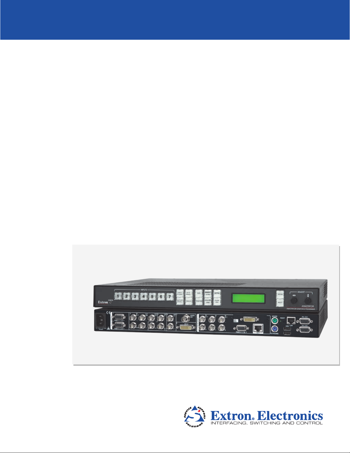
About the Annotator
The Annotator is a high performance, hardware-based annotation processor for video and
computer-video sources. It allows the presenter to draw, point, or add text to electronic
presentation materials using a touchscreen and/or a keyboard and mouse. The Annotator
supports all common analog and digital video and data formats, from composite video
to high resolution DVI, RGBHV and optional SDI/HD-SDI. Input video is scaled and made
available in a variety of output formats, including analog RGBHV and Extron MTP twisted
pair, as well as optional DVI, HD-SDI, or scan-converted video. The Annotator is ideal
for applications that require the overlay of graphics and text within AV presentations,
including schools, law enforcement, medicine, telepresence, and live events.
Extron
Annotator
50/60Hz
100-240V .5A MAX
Annotation Graphics
Processor
Laptop
Mouse
RS-232
RS-232
RESET
LAN
MOUSE
USB
DVI
OUT
RGB/R-Y, Y, B-Y
KEYBOARD
MTP
B/
B-Y
G/
Y
R/
R-Y
O
U
HDSDI/
V S
T
SDI
P
H
U
T
VID
/Y
S
DVI-D
VID
/Y
6
4 5 7
B/C
B-Y
G/Y
CR-Y
VID
R/
B-Y
R-Y
/C
3
1
I
H/HV V
N
RGB/R-Y,Y,B-Y
P
2
U
T
S
RGB/R-Y,Y,B-Y
Keyboard
Annotator
Touchscreen
Projector
Video Conference
DVD
Codec
Figure 1. Typical Annotator Application
Annotator • Introduction 1
Page 8

Denitions
The following terms are used throughout this manual:
EDID — Extended Display Identication Data. A communications protocol or instruction
set developed by VESA (Video Electronics Standards Association) for the identication of
display devices to computers using the DDC (Display Data Channel) transmission standard.
DVI — Digital Visual Interface. The digital video connectivity standard that was developed
by DDWG (Digital Display Working Group). This connection standard offers two different
connectors: one with 24 pins that handles digital video signals only, and one with 29 pins
that handles both digital and analog video. This standard uses TMDS (Transition Minimized
Differential Signaling) from Silicon Image and DDC from VESA. DVI-D is a DVI connector
that supports digital signals only, and DVI-I supports both digital and analog signals.
SDI — Serial Digital Interface. A standard definition video transmission standard based on
a 270 Mbps transfer rate. This is a 10-bit, scrambled, polarity independent interface with
common scrambling for both component ITU-R 601 and composite digital video and four
channels of embedded digital audio.
HD-SDI — High-denition version of SDI specied in SMPTE 292M. This standard
transmits audio and video over a single coaxial cable with a data rate of 1.485 Gbit/
second.
Preset — A configuration that has been stored, allowing the setup and recall of recurring
I/O congurations using the front panel, RS-232/422, or Ethernet control.
• Input – Up to 128 input presets (individual I/O congurations) may be saved and
recalled. An input preset is a user-defined set of input and picture control settings that
can be saved for each source within a system so that they can be recalled whenever
the source is active. Input presets can be recalled on any input that supports the saved
input’s video format. This type of preset saves specific settings for size, centering,
contrast, brightness, detail, zoom, and input conguration. Unlike user presets, input
presets save parameters that can be recalled only on the source that was active when
the preset was saved.
• User – Up to 16 user presets per input are available. A user preset saves specic
settings for color, brightness, detail, size, and centering. User presets are used when
a shortcut is needed to quickly recall a group of settings that relate to the current
content or current input. Each input has its own set of 16 user presets.
Auto Memory — The automatic saving and recall of input and picture controls for signals
that have been previously applied.
Annotator • Introduction 2
Page 9

Features
• Real time annotations over high resolution PC and video graphics — This allows
a presenter to draw, point, or add text in real time over live video and computer-video
presentations.
• Inputs: Two RGB or HD component video on 15-pin HD connectors; congurable
input on BNC connectors for RGB, HD/SD component video, S-video, or composite
video; component video, S-video, or composite video on BNCs; S-video or composite
video on BNCs; DVI-D; and optional SDI/HD-SDI.
• Outputs: Simultaneous scaled outputs as RGB or HD component video on BNCs,
15-pin HD, and Extron MTP twisted pair output; an optional fourth output for DVI-D,
HD-SDI, or scan-converted component video, S-video, or composite video.
• Configurable Preview and Program outputs — The outputs can be configured
as separate Preview and Program outputs. The Preview output allows a presenter
or system operator to view the annotation GUI, while the audience sees the video
and annotation through the Program outputs. This can also be used by the system
operator to preview annotations before making them live.
• Hardware-based graphics and video processing — The Annotator features a
fully hardware-based system architecture designed to deliver the performance and
operational reliability essential for mission-critical applications.
• Intuitive graphical user interface — A user friendly on-screen display enables quick
and easy annotation. Essential annotation tools are available for drawing freehand
or straight lines, adding rectangular or elliptical shapes, typing in text, highlighting
an area of an image, and pointing to an object on-screen. Customizing options are
available for text and graphics including point size and color.
• Integrated seven-input presentation switcher — The Annotator allows for
switching between DVI, RGBHV, component video, and S-video or composite video
sources. An input for SDI/HD-SDI is available as an option.
• Automatic input format detection — Each input can be set to detect the incoming
signal format, automatically reconfiguring itself to provide the appropriate decoding
and signal processing. This feature can reduce the number of required outputs for a
device, lowering system cost while improving manageability.
• RGB, HDTV, and video scaling — RGB computer-video, high denition video, and
standard definition video sources can be scaled to the desired output resolution.
• RGB upscaling and downscaling — The Annotator features an advanced scaling
engine with high quality upscaling and downscaling of high resolution computer-video
signals.
• Compatibility with popular touchscreen displays — The Annotator supports
touchscreen displays from third-party manufacturers and also can be used with a
standard keyboard and mouse.
• Optional SDI/HD-SDI input — SDI or HD-SDI signals from cameras or other
professional video equipment can easily be integrated into presentations with the
optional SDI/HD-SDI input board.
• Four simultaneous annotated video outputs — Two high resolution RGB or
component video outputs are available, as well as Extron MTP twisted pair and an
optional output that can be congured as DVI, HD-SDI, or scan-converted video.
• Extron MTP twisted pair output — This provides built-in transmission of RGB or
component video signals over twisted pair cables for long distance transmission to a
remote display. A compatible Extron MTP Series twisted pair receiver is required.
Annotator • Introduction 3
Page 10

• Optional DVI, HD-SDI, or scan-converted output — A flexible output expansion
port which can be populated to support optional DVI, HD-SDI, or scan converter
output boards. These boards serve as a third Program output and offer additional
system capabilities, such as recording or digital signal transmission.
• Output rates — A total of 81 output rates are available, including computer-video
rates up to 1920x1200, and HDTV rates up to 1080p/60 Hz.
• Image freeze control — A live image can be frozen using the annotation GUI,
the freeze button on the front panel, or through RS-232 serial control and IP Link®
Ethernet control.
• Image capture — A snapshot of the live video output, including annotations, can
be captured and stored as a BMP le on the Annotator or downloaded to a PC for
archiving. Up to 40 MB of space is available for screen captures.
• Auto-Image™ — Using the annotation GUI or the front panel, the sizing, centering,
and filtering can be automatically adjusted to optimize the output image.
• Auto Input Memory — When activated, the Annotator automatically stores size,
position, and picture settings based on the incoming signal. When the same signal is
detected again, these image settings are automatically recalled from memory.
• EDID emulation — The Annotator provides a means for specifying the rate of the
incoming DVI or VGA signal through the RS-232 serial port. EDID emulation allows
proper communication with the video source.
• Glitch-free switching — Switching is glitch-free between RGB and video inputs
with selectable cut or fade to black transitions. Presentations can be enhanced by
eliminating distracting visual jumps, glitches, and distortion commonly seen when
switching between computer and video sources.
• PIP — picture-in-picture — Allows a video source to be displayed within an RGB
image, or vice versa, with dynamic, fully adjustable window positioning for the PIP
window. PIP mode is available through RS-232 serial control or IP Link Ethernet
control.
• Picture controls — For brightness, contrast, color, tint, detail, and horizontal and
vertical positioning, sizing, and zoom. Sixteen memory presets are available for each
input to store all image settings.
• Aspect ratio conversion — Any video input can be adjusted horizontally and
vertically to meet a specific aspect ratio requirement. Alternatively, the input aspect
ratio may be specified as 4:3 or 16:9 and fixed.
• Front panel security lockout — This locks out all front panel functions except for
input selection; all functions however, are available through RS-232 control.
• Automatic 3:2 and 2:2 pulldown detection — Advanced film mode processing
techniques help maximize image detail and sharpness for NTSC, PAL, and HDTV 1080i
sources that originated from film.
• Motion adaptive 1080i to 1080p deinterlacing — High performance deinterlacing
for 1080i signals from HD sources including broadcasts and Blu-ray Disc™, allows
optimized image quality through advanced motion compensation.
• Quad standard video decoding — This uses a digital, four-line adaptive comb filter
to decode NTSC 3.58, NTSC 4.43, PAL, and SECAM video for integration into systems
worldwide.
• IP Link Ethernet monitoring and control — An IP integration technology
developed by Extron. IP Link enables the Annotator to be controlled and proactively
monitored over a LAN, WAN, or the Internet.
Annotator • Introduction 4
Page 11

• RS-232 serial control port — Using serial commands, the Annotator can be
controlled and congured via the Extron Windows-based control program (SPPCP), or
integrated into third-party control systems. Extron products use
the SIS (Simple Instruction Set) command protocol, a set of basic ASCII code
commands that allow for quick and easy programming.
• Rack-mountable — 1U, full rack width, metal enclosure
• Internal universal power supply — The 100-240 VAC, 50-60 Hz, international
power supply provides worldwide power compatibility.
Annotator • Installation 5
Page 12

Installation
This section contains installation information for the Extron Annotator. It covers the
following subjects:
• UL/Safety Requirements
• Mounting the Annotator
UL/Safety Requirements
The Underwriters Laboratories (UL) requirements listed below pertain to the safe
installation and operation of this Annotation Graphics Processor.
Important Safety Instructions
1. Read these instructions.
2. Keep these instructions.
3. Heed all warnings.
4. Follow all instructions.
5. Do not use this apparatus near water.
6. Clean only with a dry cloth.
7. Do not block any ventilation openings. Install in accordance with the manufacturer’s
instructions.
8. Do not install near any heat sources such as radiators, heat registers, stoves, or other
apparatus (including amplifiers) that produce heat.
9. Do not defeat the safety purpose of the polarized or grounding type plug. A polarized
plug has two blades with one wider than the other. A grounding type plug has two
blades and a third grounding prong. The wide blade or the third prong are provided
for your safety. If the provided plug does not fit into your outlet, consult an electrician
for replacement of the obsolete outlet.
10. Protect the power cord from being walked on or pinched particularly at plugs,
convenience receptacles, and the point where they exit from the apparatus.
11. Only use attachments/accessories specified by the manufacturer.
12. Use only with the cart, stand, tripod, bracket, or table specied by the manufacturer,
or sold with the apparatus. When a cart is used, use caution when moving the cart/
apparatus combination to avoid injury from tip-over.
13. Unplug this apparatus during lightning storms or when unused for long periods of
time.
14. Refer all servicing to qualified service personnel. Servicing is required when the
apparatus has been damaged in any way, such as power-supply cord or plug is
damaged, liquid has been spilled or objects have fallen into the apparatus, the
apparatus has been exposed to rain or moisture, does not operate normally, or has
been dropped.
Annotator • Installation 6
Page 13

Mounting the Annotator
If the Annotator is to be rack mounted, it is important to mount it before cabling it. Four
rubber feet are included with the unit. Install the feet only if the unit is to be mounted on
a table top (see “Tabletop placement” below).
Tabletop Placement
For tabletop placement, install the self-adhesive rubber feet/pads (provided) onto the four
corners of the bottom of the device.
UL Guidelines for Rack Mounted Devices
The following Underwriters Laboratories (UL) guidelines pertain to the safe installation of
the Annotator in a rack.
1. Elevated operating ambient temperature — If installed in a closed or multi-unit rack
assembly, the operating ambient temperature of the rack environment may be greater
than room ambient temperature. Therefore, install the device in an environment
compatible with the maximum ambient temperature (Tma = +122 °F, +50 °C) as
specied by Extron.
2. Reduced air flow — Install the equipment in a rack so that the amount of air flow
required for safe operation of the equipment is not compromised.
3. Mechanical loading — Mount the equipment in the rack so that a hazardous
condition is not achieved due to uneven mechanical loading.
4. Circuit overloading — Connect the equipment to the supply circuit and consider the
effect that circuit overloading might have on overcurrent protection and supply wiring.
Appropriate consideration of equipment nameplate ratings should be used when
addressing this concern.
5. Reliable earthing (grounding) — Maintain reliable grounding of rack-mounted
equipment. Pay particular attention to supply connections other than direct
connections to the branch circuit (for example, use of power strips).
Rack Mounting
To rack mount the Annotator, attach brackets to the side of the unit, as shown below, and
secure it to the the rack. See figure below.
Rack Mount
Bracket
Figure 2. Mounting the Annotator
Annotator • Installation 7
Page 14

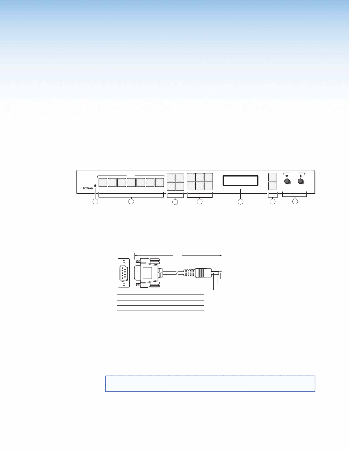
Rear Panel
Features and
Connections
This section describes the rear panel features and how to connect the cables.
Rear Panel Features
The illustration below shows the rear panel features of the Annotator.
VID
4
5
B/C
/Y
B-Y
B-Y
R-Y
/C
4
100-240V 2A
50/60 Hz
1
I
N
P
U
T
S
1
RGB/R-Y,Y,B-Y
2
RGB/R-Y,Y,B-Y
3
R/
G/Y
R-Y
VID
V
H/HV
2
3
17
RESET
15
LAN
RS-232
USB
RS-232
14
12
MOUSE
Y
B-Y
B/
KEYBOARD
13
LORES
OUT
RGB/R-Y, Y, B-Y
10
C
VID
Y/
R-Y
G
R/
MTP
9
11
7
7
HDSDI/SDI
VID
/Y
6
C
5
O
U
T
P
DVI-D
U
T
S
6
G/YB/
R/
R-Y
HV
8
B-Y
S
16
Figure 3. Annotator Rear Panel Features
AC power connector
a
RGB/YUV-HD VGA connectors (inputs 1 and 2)
b
Universal BNC connectors (input 3)
c
Component/S-video/composite BNC
d
connectors (input 4)
S-video/composite BNC connectors (input 5)
e
DVI connector (input 6)
f
(Optional) HD-SDI/SDI connector (input 7)
g
RGB/YUV-HD BNC ouput connectors
h
RGB/YUV-HD VGA output connector
i
Power and Video Input Connections
a AC power connector — After connecting all input and output cables, plug a
standard IEC power cord from a 100 to 240 VAC, 50 Hz to 60 Hz power source
into this receptacle.
b RGB/YUV-HD VGA connectors (inputs 1 and 2) — Connect high resolution
computer-video input signals to either of the two 15-pin HD connectors.
(Optional) output card (scan converter shown)
j
MTP twisted pair output connector
k
PS/2 mouse port
l
PS/2 keyboard port
m
USB A ports
n
RJ-45 Ethernet LAN connector
o
9-pin RS-232 connectors
p
Reset button and LED
q
Annotator • Rear Panel Features and Connections
8
Page 15
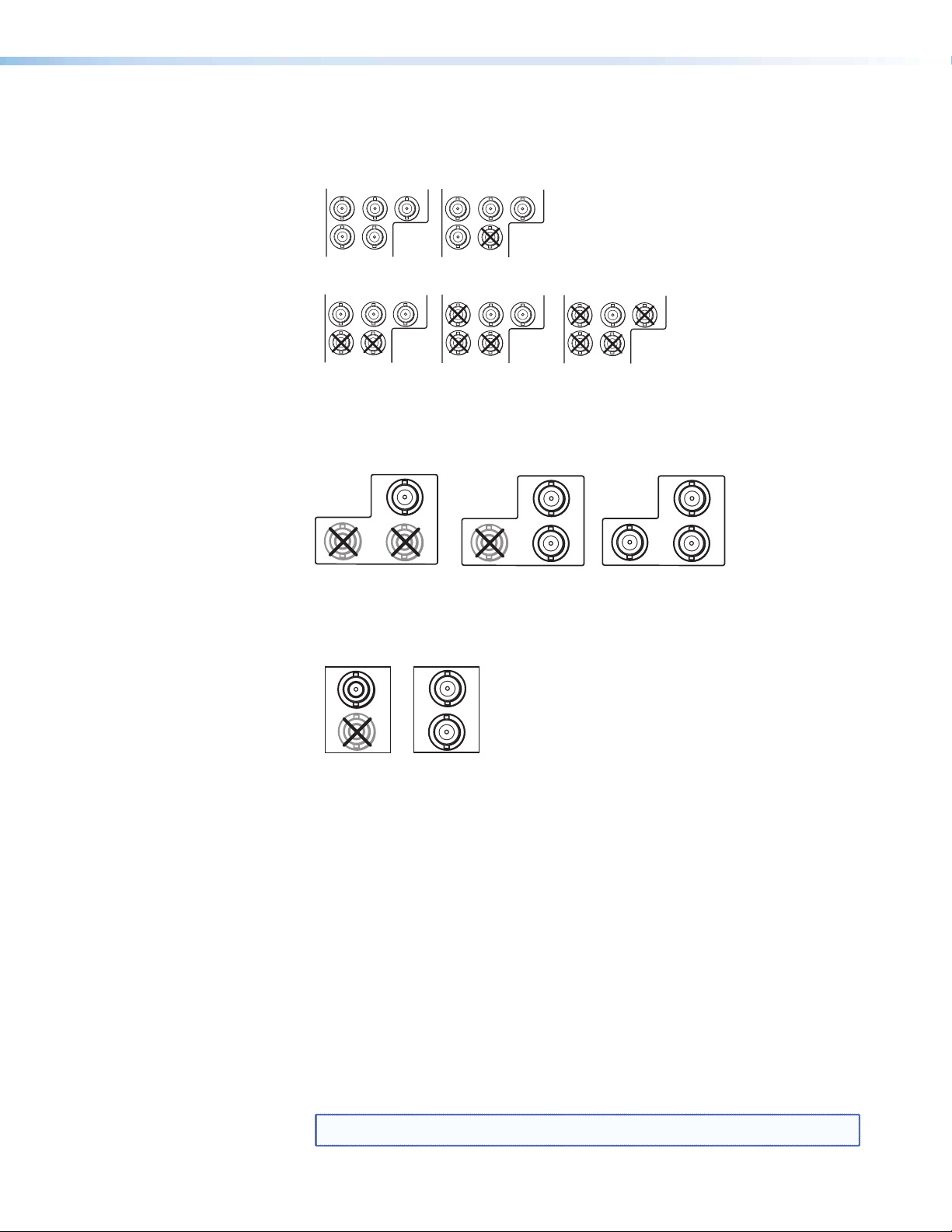
c Universal BNC connectors (input 3) — Connect a high resolution computer-
RGBS/RGBcvS
video, component, S-video, or composite input signal to this group of female
BNC connectors.
RGBHV
3
R/
R-Y
B/C
G/Y
VID
3
B-Y
R/
R-Y
B/C
G/Y
B-Y
VID
H/HV V
RGsB/Component Video
(Y, R-Y, B-Y)
3
R/
R-Y
H/HV V
B/C
G/Y
B-Y
VID
3
H/HV V
R/
R-Y
H/HV V
Composite VideoS-video (YC)
B/C
G/Y
VID
3
B-Y
R/
R-Y
H/HV V
B/C
G/Y
B-Y
VID
d Composite/S-video/component BNC connectors (input 4) — Connect a
composite video, S-video, or SD component video signal. Connect cables as
shown below.
Composite Video
4
R-Y
VID
/Y
B-Y
/C
S-video (YC)
4
R-Y
Component Video (Y, R-Y, B-Y)
VID
/Y
B-Y
/C
4
R-Y
VID
/Y
B-Y
/C
e S-video/composite video BNC connectors (input 5) — Connect S-video or
composite video input signals to this pair of female BNC connectors. Connect
cables as shown below.
VID
/Y
S-video (YC)
VID
5
/Y
Composite Video
5
C
C
f DVI-D connector (input 6) — Connect a high resolution digital input signal to
this DVI-I connector.
g Optional input board (HD-SDI/SDI with BNC shown) connector (input 7)
— Connect an appropriate input to the optional board connector.
Output, User Interface, and Control Connections
h RGB/YUV-HD BNC connectors — Connect a display to these for RGB or
HD component video output.
i RGB/YUV-HD 15-pin VGA connector — Connect a display to this for RGB or
HD component video output.
j Optional output card (scan converter with BNC connectors shown) —
Connect a display to this for composite, S-video, or component video output.
k MTP output — Connect a mini twisted pair receiver to this port
NOTE: MTP output supports only RGBHV and RGBS video formats.
Annotator • Rear Panel Features and Connections
9
Page 16

l PS/2 mouse port — Connect a PS/2 mouse to this port for annotation use.
m Keyboard port — Connect a Microsoft
annotation use.
®
compatible keyboard to this port for
n USB A ports — Connect up to twenty touch panel devices (using USB hubs), or
a USB mouse and keyboard to these ports.
o LAN Ethernet port — Connect the Annotator to an Ethernet LAN or WAN via
this RJ-45 connector. Ethernet control allows the operator to control the
processor from a remote location. When connected to an Ethernet LAN or WAN,
the device can be accessed and operated from a computer running a standard
Internet browser. The Link LED lights green when the Annotator is connected
to an Ethernet LAN, and the Act LED flickers amber, indicating data transmission
as the devices communicate.
CAUTION: Do not connect the MTP cable to the LAN port, or connect the
LAN cable to the MTP port.
NOTE: Do not use standard telephone cables, as they do not support
Ethernet or Fast Ethernet. See the “Ethernet Connection” section,
for correct cabling.
Do not stretch or bend cables. Transmission errors can occur.
See the “SIS Communication and Control” section for definitions of
the SIS commands, and the “
Program” section to install and use the control software.
Signal Processing Products Control
p RS-232 9-pin ports — These connectors provides for two-way
RS-232 communication. Connect a host computer or control system via a
9-pin D connector p for serial RS-232 or RS-422 control.
For touch panels, using a null RS-232 cable only, connect the touchscreen to the
Annotator via either of the RS-232 ports. RS-232 driver configuration is necessary
and can be done using the Signal Processing Products Control Program. Within
the SPPCP program click Help > Contents for configuration instructions.
The default protocol is 9600 baud, 1 stop bit, no parity, and no flow control.
q Reset button and LED — This button is used to reset the switcher to any one of
four different states. The LED indicates the status during the resetting procedure.
Refer to the “Resetting the Unit with the Reset Button” section, for details.
Installation and Cabling
Step 1 — Mount the unit
Turn off or disconnect all equipment power sources and rack mount the Annotator
(see page 7).
Step 2 — Connect inputs
Connect inputs from video sources to the applicable connectors marked “Inputs”
(see pages 8 and 9, b to g for connector types).
Step 3 — Connect outputs
Connect video output devices to the applicable I/O board connectors marked
“Outputs” (see page 9, h to k for connector types).
Step 4 — Connect user interface devices
PS2 mouse and keyboard ports (l and m) — Connect a mouse and/or a keyboard
for annotation use.
Annotator • Rear Panel Features and Connections
10
Page 17
Step 5 — Connect touch panel devices
Via USB A ports — Connect a touchpanel device to either port as desired. For most
devices no configuration is needed.
Via RS-232 ports — Connect a touchpanel device to either port as desired.
RS-232 driver configuration is necessary and can be done using the Signal Processing
Products Control Program. See the “Signal Processing Products Control Program”
section for details.
Step 6 — Connect control devices
LAN Ethernet port — Connect to an Ethernet LAN or WAN via this RJ-45 connector
to control the processor from a remote location, using a PC’s Internet browser. See
o
the ”Ethernet Connections” section for network cable termination method. Ethernet
connection indicator LEDs marked indicate the status of the Ethernet connection. The
green LED lights when connected to an Ethernet LAN, and the amber LED ickers as
the devices communicate.
Remote ports — For serial RS-232 or RS-422 control, connect a host computer or
control system via the 9-pin D connector p. RS-232 protocol (default values):
• 9600 baud • 1 stop bit • no parity • 8 data bits • no ow control.
NOTE: See “SIS Communication and Control” section for definitions of the
SIS commands and “Signal Processing Products Control Program”
section to install and use the control software.
Step 7 — Connect power
AC power connector — Plug in a standard IEC power cord from a 100 to 240 VAC,
50 - 60 Hz power source into this receptacle a.
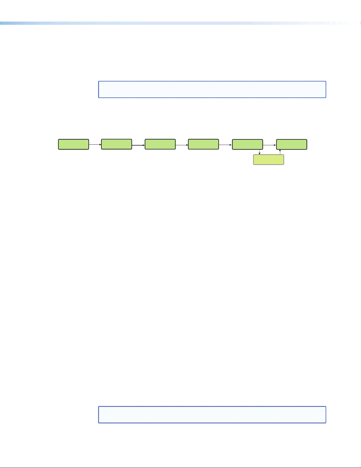
Powering Up
When applying power to the Annotator, the unit undergoes a start-up self testing
sequence (see image below) and then the LCD displays the default display cycle.
Apply
Power
10
sec.
Extron
Annotator v1.xx
3
sec.
Loading OSD file
complete
Default display cycle
When in use but not in any menu mode, the LCD screen defaults to cycling through the
input/output configuration currently installed. The displayed content may vary, depending
on the input video signal type. See the figure below for a typical default display cycle.
Extron
Annotator v1.xx
3
sec.
All buttons flash in sequence
(green, red, amber).
1
sec.
1
All input buttons
flash consecutively (amber).
Figure 4. Typical Default Cycle
The default display cycle shows the output resolution and the refresh rates for the
currently selected input.
2
Sorting graphics
3
sec.
Boot-up sequence
files
complete
Key
Menu and Next buttons
remain lit.
MENU
= unlit
= lit
NEXT
1
sec.
1
Last active input
button remains lit.
= flashing
Default Display Cycle
1
sec.
2
NOTE: The input and output rates shown in the default display
cycle may differ, depending on the type of video signal active.
Input #2
60.0kHz 75.0Hz
2
sec.
1024x768 60.0Hz
2 sec.
Output Rate
Annotator • Rear Panel Features and Connections
11
Page 18
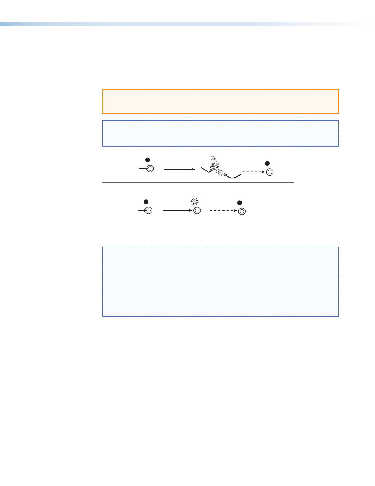
Resetting the Unit with the Reset Button
1
2
There are four reset modes (numbered 1, 3, 4, and 5 for the sake of comparison with
Extron IPL products) that you can access by pressing the Reset button on the rear panel.
The Reset button is recessed, so use a pointed stylus, ballpoint pen, or Extron Tweeker to
press it. See the table on page 13 for a summary of the reset modes.
CAUTION: Review the reset modes carefully. Using the wrong reset mode may result
in unintended loss of flash memory programming, port reassignment, or
processor reboot.
NOTE: The reset modes listed in the table close all open IP and Telnet connections and
close all sockets. Also, each mode is a separate function, not a continuation
from mode 1 to mode 5.
Mode 1
Press and hold
the Reset button.
Modes 3, 4, and 5
Press and hold for
3, 6, or 9 seconds.
RESET
Reset LED flashes once,
twice, or three times.
RESET
Apply Power
Release, then immediately
press and release again. Reset
LED flashes in confirmation.
RESET
Release Reset button.
RESET
RESET
Figure 5. Resetting the Annotator
NOTE: After a mode 1 reset is performed, update the Annotators’s firmware to the
latest version. Do not operate the firmware version that results from the
mode 1 reset. If the factory default firmware is to be used, that version must
be uploaded again.
If you do not want to update firmware, or you performed a mode 1 reset by
mistake, cycle power to the device to return to the firmware version that was
running before the mode 1 reset. Use the 0Q SIS command to confirm that
the factory default firmware is no longer running (look for the asterisk [*]
following the version number).
See the table on next page for a summary of the reset modes.
Annotator • Rear Panel Features and Connections
12
Page 19

Annotator Reset Mode Summary
Mode Activation Result Purpose/Notes
Hold down the recessed Reset button
1
while applying power to the unit
The Annotator reverts to the factory
default firmware. Event scripting does
not start if the device is powered in this
mode. All user files and settings (drivers,
adjustments, IP settings) are maintained.
This mode reverts to the
factory default firmware
version if incompatibility
issues arise with user-loaded
firmware.
NOTE: After a mode 1 reset is
performed, update the
Annotator firmware to
the latest version. Do not
operate the firmware
version that results from
this mode reset. If you
want to use the factory
Use Factory Firmware
Hold down the Reset button for about 3
3
sec. until the Power LED blinks once, then
release and press Reset momentarily (<1
Events
Run/Stop
Settings
Reset all IP
Defaults
sec.) within 1 second.
Hold down the Reset button for about
4
6 sec. until the Power LED blinks twice
(once at 3 sec., again at 6 sec.). Then
release and press Reset momentarily (for
<1 sec.) within 1 second.
NOTE: Nothing happens if the
Hold down the Reset button for about 9
5
sec. until the Power LED blinks three times
(once at 3 sec., again at 6 sec., again
at 9 sec.). Then release and press Reset
momentarily (for <1 sec.) within 1 second.
NOTE: Nothing happens if the
Reset to Factory
default firmware, you
must upload that version
again. See page 69 or 87
for details on uploading
firmware.
momentary press does not
occur within 1 second.
momentary press does not
occur within 1 second.
NOTE: If you do not want to update
firmware, or you performed
a mode 1 reset by mistake,
cycle power to the Annotator
to return to the firmware
version that was running prior
to the mode 1 reset. Use the
0Q SIS command to confirm
that the factory default
firmware is no longer running
(look for asterisks following
the version number.)
This mode turns events on or off.
NOTE: Nothing happens if the
momentary press does not
occur within 1 second.
This mode does the following:
• Enables ARP capability.
• Sets the IP address back to factory default
(192.168.254.254).
• Sets the subnet back to factory default.
• Sets the default gateway address to the
factory default.
• Sets port mapping back to factory default.
• Turns DHCP off.
• Turns events off.
This mode performs a complete reset to
factory defaults (except the firmware).
• Does everything mode 4 does.
• Removes button/touchpanel congurations.
• Resets all IP options.
• Removes scheduling settings.
• Removes/clears all les from the unit.
NOTE: User-dened
web pages
may not work
correctly if
using an earlier
firmware
version.
This mode is useful for
troubleshooting.
This mode enables you to set
IP address information using
ARP and the MAC address.
This mode is useful if you
want to start over with
configuration and uploading,
and also to replace events.
Annotator • Operation 13
Page 20
Operation
This section of the manual discusses the operation of an Annotator unit and is divided
into four sections:
• Front Panel Overview
• The Annotator Menu System
• Setting the Front Panel Locks (Executive Modes)
• Setting up the Annotator to Work with a Matrix Switcher
Front Panel Overview
INPUTS
6 754321
1
2
UNDO
/CLEAR
CAPTURE
/RECALL
AUTO
IMAGE
FREEZE
3
SIZE
POSITION
BRIGHT
/CONT
COLOR
/TINT
4
DETAIL
ZOOM
/PAN
MENU
NEXT
5
6 7
ADJUST
ANNOTATOR
ANNOTATION GRAPHICS PROCESSOR
Figure 6. Front Panel Features
a Front panel configuration port — Connect a control system or computer to
this (RS-232) port using an optional 9-pin D to 2.5 mm mini jack TRS RS-232
cable, part 70-335-01 (see below). RS-232 protocol (default values):
• 9600 baud • 1 stop bit • no parity • 8 data bits • no ow control
6 feet
1
6
9
5
9-pin D Connection TRS Plug
Pin 2 Computer Rx line Tip
Pin 3 Computer Tx line Ring
Pin 5 Computer's signal ground Sleeve
Tip
Ring
Sleeve (Gnd)
Figure 7. Front 2.5 mm Port Configuration Cable, Part 70-335-01
b Input selection buttons — Select/switch inputs and indicate which input is
active.
c Special function buttons — These four buttons are:
• Undo/Clear — Allows a reversal of up to seven of the last annotation points or
clears selected annotations.
NOTE: See the “On Screen Annotation” section for an overview of image
annotation.
• Auto Image — Initiates auto image adjustment on the selected input.
• Capture/Recall — Allows the capture and saving of the current image, or the
recall of a saved image.
Annotator • Operation 14
Page 21

• Freeze — Allows the current displayed image to be frozen or unfrozen as desired.
d Picture control buttons — These six buttons are:
• Size — Allows adjustment to the displayed image size.
• Bright/Cont — Allows adjustment of the brightness and contrast settings for the
displayed image.
• Detail — Allows adjustment of the detail (sharpness) settings for the displayed
image.
• Position — Allows horizontal and/or vertical position adjustment of the displayed
image.
• Color/Tint — Allows adjustment of the color and tint settings for the displayed
image.
• Zoom/Pan — Allows displayed image to be zoomed in or out, or panned
horizontally and/or vertically.
NOTE: Adjustments are made using either or both Adjust knobs ([ {).
e LCD display — This LCD screen displays two rows of menu, control response,
and configuration text.
f Menu navigation buttons — These two buttons give access to menu
commands.
See “The Annotator Menu System” section in this chapter.
• Menu button — This button, always lit amber, gives direct access to a series of
five menus.
• Next button — This button, always lit amber, allows page changes within each
one of the menus, and to exit the menu cycle.
g Adjustment knobs — These two knobs are used with the picture control buttons
and the menu navigation buttons to adjust settings.
Switching Inputs
To switch inputs, simply press the desired input button. The button lights amber when an
active video signal is detected. If the output is configured correctly for the display device,
the image changes to the new input. An inactive signal gives no image.
Button Backlighting
The buttons can be backlit a dimmed amber.
To turn the backlighting on or off, press and hold the Bright/Cont and Color/Tint buttons
simultaneously until the buttons become lit or unlit.
Annotator • Operation 15
Page 22
The Annotator Menu System
The Annotator can be congured using the menu system, via the Extron Simple Instruction
Set (SIS) of commands, or via the Extron Signal Processing Products Control Program
(SPPCP) software program, through an RS-232 or LAN connected PC.
NOTE: For methods see “SIS Communication and Control” and “Signal Processing
Products Control Program” section.
The Annotator has six front panel conguration menus: User Presets, Input Conguration,
Output Conguration, Advanced Conguration, View Comm Settings. A hidden menu
(Edit Comm Settings) is also accessible. If the optional Scan Converter board is installed a
scan converter configuration menu becomes available.
User
Presets
Menu
Input
Configuration
Menu
Output
Configuration
Menu
Advanced
Configuration
Menu
View Comm
Settings
Menu
Scan Converter
Configuration
Optional
Exit Menu
Press NEXT
Figure 8. The Annotator Front Panel Configuration Menus
Overview of Menus
See image on next page.
User Presets
This menu allows unnecessary the user to save the current image settings to a preset
number (1-16), and recall any saved preset to become the current image settings. Each
input has sixteen user selectable presets.
Input Configuration
This menu allows configuration of the following setting for any selected input:
Input type, film detection, vertical and horizontal start points, pixel phase, the number of
Output Configuration
total and active pixels and the number of active lines.
This menu allows configuration of the following settings for the active output:
Resolution and refresh rate (see table on page 20), output type, and sync polarity (where
applicable).
Advanced Configuration
This menu allows advanced configuration of the following Annotator settings:
Auto Image, Auto Memories, Aspect Ratio, Input EDID (see table on page 20), RGB
Delay, Switch Effect, Test Pattern, MTP Pre-Peaking, Internal Temp (view only), Calibrate
Panels, and Reset to Factory defaults.
View Comm Settings
This menu allows the user to view the following serial and IP settings for the unit:
Serial port baud rate, MAC address, DHCP (Dynamic Host Conguration Protocol) setting,
IP address, subnet mask address, and gateway address
NOTE: These settings can not be edited from within this menu. See”Edit Comm
Settings (hidden)” on next page.
Annotator • Operation 16
Page 23
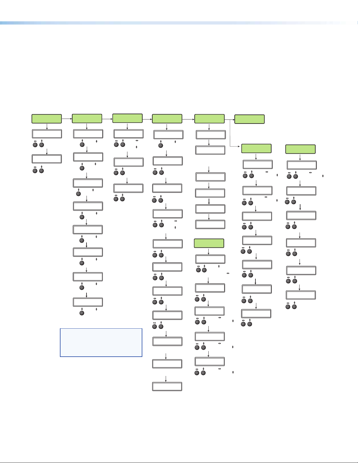
Edit Comm Settings (hidden)
To display and enter this menu, press and hold the Detail and Color/Tint buttons
simultaneously and then press Next. The hidden menu appears.
This menu allows the user to edit the following serial and IP settings:
Serial port baud rate, DHCP mode, IP address, subnet mask, and gateway address.
Exit Menu
At this menu pressing Next exits the menu system and returns to the default cycle.
Input
Configuration
Next
Input #x
RGB
Rotate to select
video input type.
Next
Input #x
Film Detect On
Rotate to turn
Film Detect on
or off.
Next
Input #x
Vert Start 128
Rotate to adjust
Vertical Star t value.
Next
Input #x
Horz Start 128
Rotate to adjust
Horizontal Start value.
Next
Input #x
Pixel Phase 28
Rotate to adjust
Pixel Phase value.
Next
Input #x
Total Pix *2200
Rotate to adjust
Total Pixel value
(* = default).
Next
Input #x
Active Pixels *1920
Rotate to adjust
Active Pixels value
(* = default).
Next
Input #x
Active Lns *1080
Rotate to adjust
Active Lines value
(* = default).
Menu
Next
Rotate either to
select a preset to
recall settings.
Next
Rotate either
to select a preset
to save current
settings to.
Menu
User
Presets
Recall Preset
<NA>
Save Preset
<02>
*NOTE To activate the hidden menu “Edit Comms”,
press and hold Detail and Color/Tint buttons
simultaneously, then press Next.
**NOTE The Scan Coverter and Aux Scaler menus are
only available when the applicable optional I/O
board is installed.
Output
Configuration
Next
Resol 1024x768
Refresh 60.00Hz
Rotate to adjust
Resolution value
Rotate to adjust
Refresh rate.
Next
Output Type
RGBHV
Rotate either to
adjust Output
type value.
Next
Sync Polarity
H Neg V Pos
Rotate either to
adjust Sync
Polarity values.
Menu
Advanced
Configuration
Auto Image
Input #x Off
Rotate to turn
Auto Image mode
On or Off.
Auto Memories
On
Rotate either to turn
Auto Memories On
or Off.
Aspect Ratio
FILL
Rotate either to select
Aspect Ratio mode.
Input EDID
1024x768 60.0Hz
Rotate to adjust
Resolution value
Rotate to adjust
Refresh rate.
RGB Delay
0.5 Seconds
Rotate either to adjust
RGB Delay value.
Switch Effect
Dissolve
Rotate either to
change Switch Effect.
Test Pattern
Color Bars
Rotate either to
change Test Pattern.
MTP Pre-Peaking
Off
Rotate either to turn
MTP Pre-Peaking
On or Off.
Internal temp
96 F 35 C
Indicates Internal temperature
(not adjustable).
Calibrate Panels
Press size
Press Size to callibrate
panel sizes.
Reset to Factory
Press Detail
Press Detail to reset unit
to factory settings.
Next
Next
Next
Next
Next
Next
Next
Next
Next
Next
Next
Menu
9600 RS232
This is set at the factory
and cannot be changed
in “Edit Comm Settings”
menu.
Gateway Address
9600 RS232
<192>168.254.254
<255>255.000.000
Gateway Address
<000>000.000.000
View Comm
Settings
Next
Serial Port
Next
MAC Address
005A6003C24
Next
DHCP Mode
On
Next
IP Address
192.168.254.254
Next
Subnet Mask
255.255.000.000
Next
000.000.000.000
“Hidden” Menu *
Edit Comm
Settings
Next
Serial Port
Rotate to select
RS-232 or RS-422
mode. Rotate to
change baud rate.
Next
DHCP Mode
<On>
Rotate either to turn
DHCP mode On or Off.
Next
IP Address
Rotate to select
octet field. Rotate
to change address.
Next
Subnet Mask
Rotate to select
octet field. Rotate
to change address.
Next
Rotate to select
octet field. Rotate
to change address.
Menu
Exit Menu
Press NEXT
Optional I/O
Board Menu **
Scan
Converter
Next
H Size V
2048 2048
Rotate to adjust
H value. Rotate
to adjust V value.
Next
H Center V
2048 2048
Rotate to adjust
H value. Rotate
to adjust V value.
Next
Output Format
S-video/Comp
Rotate either to
select output format.
Next
Output Standard
NTSC
Rotate either to
select output standard.
Next
Flicker Filter
3
Rotate either to
adjust flicker filter.
Next
H Filter
0
Rotate either to
adjust H filter.
Next
Encoder Filter
0
Rotate either to
adjust encoder filter.
Optional I/O
Board Menu **
Aux
Scaler
Next
Resol 1024x768
Refresh 60.00Hz
Rotate to adjust
resolution. Rotate
to adjust refresh rate.
Next
Output Type
RGBHV
Rotate either to
select output type.
Next
Sync Polarity
H neg V neg
Rotate either to
adjust sync polarity
values.
Next
Aspect Ratio
Follow
Rotate either to
select aspect
ratio mode.
Next
Detail
64
Rotate either to
adjust detail level.
Next
Test Pattern
Crop
Rotate either to
select test pattern.
Figure 9. Annotator Menu System Overview
Annotator • Operation 17
Page 24

Scan Converter Conguration
This menu, displayed only when the optional scan-converter board is installed, allows the
user to configure the settings for scan-converted outputs.
Aux Scaler Conguration
This menu, displayed only when the optional aux scaler board is installed, allows the user
to configure the settings for aux scaler outputs.
Using the Menus
To configure the Annotator using any of the menus, do the following:
1. Press the Menu button repeatedly to reach the desired configuration menu.
2. Press the Next button repeatedly to go to the desired submenu.
3. The LCD shows the current values. Observe the LCD and rotate either (or both) Adjust
knob to change the values as desired.
NOTES: Pressing the Menu button within any level takes the user back to the current top
When in any menu for approximately 25 seconds and no buttons have been
level menu.
pressed or Adjust knobs rotated, the unit times out and returns to the default
cycle.
User Presets
Within this menu up to 16 presets can be saved or recalled.
Save a user preset
1. From the default display cycle press Menu to enter the User Presets submenu.
2. Press Next twice to go to the Save Preset menu.
3. Rotate either front panel Adjust knob to select a preset (1 to 16)
to save the current settings to. Default setting is <N/A>.
Select <N/A> and press Next to move to the next submenu without saving.
4. Press Next to save the current image settings to the selected preset number.
The Preset is saved and the LCD goes back to the top level User Preset menu.
NOTE: If an existing preset is chosen to save to, the previous settings are overwritten
in favor of the new (current) settings.
Recall a user preset
1. From the default display cycle press Menu to enter the User Presets submenu.
2. Press Next to go to the Recall Preset menu.
3. Rotate either front panel Adjust knobs ([{) to select a preset
(1 to 16) to recall as the current settings. Default setting is N/A.
Select <N/A> and press Next to move to the next submenu without recalling.
4. Press the Next button. The preset is recalled, the image changes to the recalled
settings and the LCD goes back to the top level User Preset menu.
Save Preset
<N/A>
Recall Preset
<02>
Annotator • Operation 18
Page 25
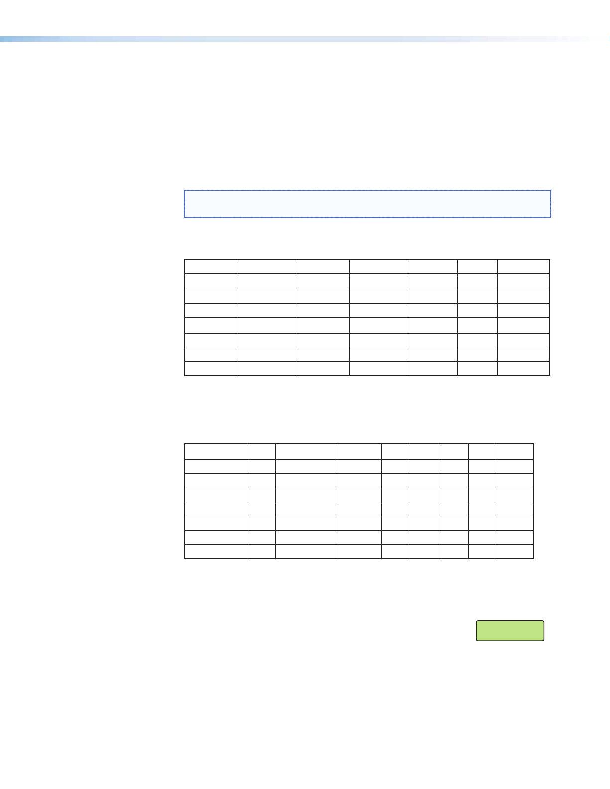
Input Conguration
Within this menu any of the seven inputs can be congured. Each input has different
settings depending on the signal format. Consult the tables below for signal formats per
input and possible adjustments per signal format.
To configure inputs:
1. From the top level Input Configuration menu press the Next button to bring up the
input selection screen. The active input is displayed on the LCD with current signal
format.
NOTE: If the input shown is not the one to be adjusted, press the desired input
2. With the correct input displayed, rotate the right Adjust knob ({) to change the signal
format (refer to table below for signal type per input).
Input 1 Input 2 Input 3 Input 4 Input 5 Input 6 Input 7
*RGB *RGB *RGB *YUVi *S-Video *DVI *SDI
YUVp/HDTV YUVp/HDTV YUVp/HDTV S-Video Composite HD-SDI
Auto Detect Auto Detect RGBcvS Composite Auto Detect Auto Detect
Figure 10. Signal Formats per Input (*= Default Value)
button.
YUVi Auto Detect
S-video
Composite
Auto Detect
3. Press the Next button to go to the next setting. If necessary repeat pressing Next until
the desired level is attained. Refer to the table below for adjustable settings for each
signal format.
Input Format RGB YUVp/HDTV RGBcvS YUVi S-vid DVI SDI HD-SDI
Film Detect X X X X X X X X
H Start X X
V Start X X
Phase X X
Total Pixels X X
Active Pixels X X X X X X X
Active Lines X X X X X X X
Figure 11. Adjustments Possible per Signal Format
4. At the desired setting (for example, Horizontal Start on input 2 with a YUVp/HDTV
signal, see image at right), rotate the right Adjust knob ({) to adjust the settings value
as desired (here to 122).
5. Repeat steps 3 and 4 for each setting as desired.
Input #2
Horz Start 122
6. When complete press Menu once or Next repeatedly to return
to the top level menu. Alternatively, allow the unit to time out to return to the default
cycle.
Annotator • Operation 19
Page 26

Output Conguration
Using this menu, resolutions, refresh rates, output signal types, and sync polarity can be
selected and adjusted for an output. See the table below for resolution and refresh rates.
1. Press Next to bring up the Resolution submenu. In this submenu, the resolution and
refresh rate can be adjusted.
2. Rotate the left front panel Adjust knob ([) to adjust the resolution value, and rotate
the right Adjust knob ({) to adjust the refresh rate.
Resolution 23.98 Hz 24 Hz 25 Hz 29.97 Hz 30 Hz 50 Hz 59.94 Hz *60 Hz 75 Hz
640x480 X X X
800x600 X X X
852x480 X X X
1024x768 X X X
1024x852 X X X
1024x1024 X X X
1280x768 X X X
1280x800 X X X
1280x1024 X X X
1360x765 X X X
1360x768 X X X
1365x768 X X X
1366x768 X X X
1365x1024 X X X
1440x900 X X X
1400x1050 X X
1680x1050 X X
1600x1200 X X
1920x1200 X X
480p X X
576p X
720p X X X X X X
1080i X X X
1080p X X X X X X X X
2048x1080 X X X X X X X X
1080p CVT X
Figure 12. Output Resolution/Refresh Rate Table
3. Press Next to enter the next submenu, Output Type. Within this submenu the output
signal type (RGBHV, RGsB, YUV bi-level, or YUV tri-level) can be selected.
4. Rotate either front panel Adjust knob ([{) to select the output signal type.
5. Press Next to enter the next submenu, Sync Polarity. Within this submenu, the Sync
Polarity can be set (H- V-, H+ V-, H+ V+, or H- V+).
6. Rotate either front panel Adjust knob ([{) to select the sync polarity.
NOTE: An incorrect sync polarity setting will result in the loss of the output image.
7. Press Next or Menu to return to the Output Configuration.
Annotator • Operation 20
Page 27
Advanced Conguration
Within this menu auto imaging and auto memory can be turned on or off, input EDID can
be set, RGB delay value adjusted, the switch effect chosen, a test pattern selected to aid
setting up the display, and the MTP pre-peaking turned on or off. In addition the internal
temperature can be read, the touch panel display can be calibrated, and the unit can be
reset to factory default settings.
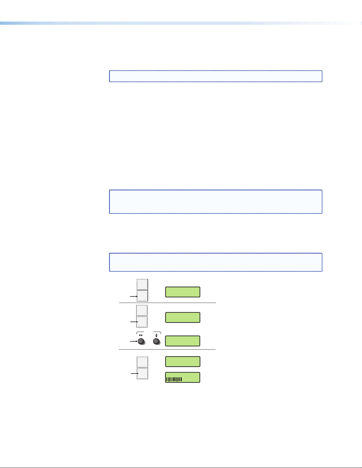
1. Press Next to enter the first sublevel, Auto Image. The current active input and setting
status is displayed.
NOTE: At any submenu, if the input is incorrect, press the desired input button, and
then proceed with the setting adjustment.
2. With the applicable input showing, rotate the right Adjust knob ({)
to turn the Auto Image on or off.
Auto Image
Input #2 On
3. Press Next to enter the next sublevel, Auto Memories, and rotate either Adjust knob
([{) to turn the Auto Memory on or off.
4. Press Next to enter the next sublevel, Aspect Ratio, and rotate either Adjust knob
([{) to select Fill or Follow.
5. Press Next to go to the next sublevel (Input EDID), or press Next
repeatedly to get to any applicable level. At each level, rotate
Input EDID
1024x768 60.0Hz
the Adjust knobs (right only or both) as needed to change the
settings to the desired value.
NOTES: • The Input EDID setting adjustment applies only to the VGA and DVI inputs.
See figure 12 for resolution and refresh rate details.
• For some settings (such as panel calibration) follow on-screen instructions.
• The internal temperature is a “read-only” screen. No adjustment is possible.
The following test pattern settings are available:
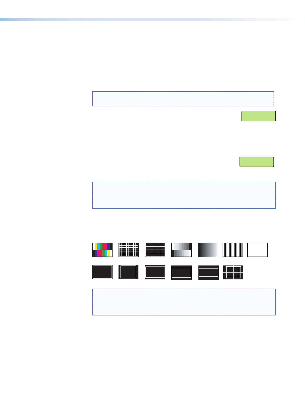
None (default), Split Color Bars (8), Crosshatch 4x4, 32 Level Grayscale, Ramp, Alternating
Pixels, Whiteeld, Crop, 1.33 Aspect ratio, 1.78 Aspect ratio, 1.85 Aspect ratio, 2.35
Aspect ratio, Safe Area, Blue Mode.
Color Bars
Crop
Crosshatch
1.33 Aspect
4x4 Crosshatch
1.78 Aspect
Split Grayscale
1.85 Aspect 2.35 Aspect
Ramp
Alternating
Pixels
Safe Area 5% 10%
White Field
NOTE: The test patterns may vary based on the output rate selected. For example, if
a 4:3 rate is selected, then the 4:3 crosshatch (32x24) and aspect ratio crop
patterns appear. The raster border is independent of the aspect ratio, always
surrounding the active area of the screen.
If a touchpanel screen is attached to the Annotator, the touch accuracy can be calibrated
using the Calibrate Panels setting in the Advanced configuration menu.
1. Within the Advanced Conguration menu press Next repeatedly to cycle to the
Calibrate Panels submenu.
2. Press the Size button and observe the touchpanel screen. A cross appears in the upper
left corner. Tap the screen at the cross, and repeat at each cross.
Annotator • Operation 21
Page 28
3. After tapping the fourth cross, the unit saves the calibration data and restarts the
Step 1
sequence. Repeat the process for each connected touchscreen.
4. Press any front panel button to exit the sequence and save the data.
NOTE: See page 32 for detailed touchscreen setup instructions.
Capture/Recall Settings (front panel activated)
A snapshot of the currently displayed image (including annotations) can be captured and
saved to the Annotator memory using the front panel Capture/Recall button, the Next
button, and the two Adjust knobs. This image or any other saved image can then be
recalled and output to the active display at a later time.
To capture an image:
1. Press and hold the Capture/Recall button for 3 seconds. The LCD displays “IMAGE
CAPTURE”.
2. Press Next to enter the Save As menu, the LCD displays “Save As: <N/A>”.
Use either Adjust knob to scroll through 16 image names, (IMG01.bmp through
IMG16.bmp) to select a suitable name.
NOTE: When saving an image to a selected name, any image previously saved
with that selected name is overwritten in favor of the newly saved
image.
3. When the desired image name is reached, press Next. The LCD displays “Saving image
Please wait.” The display then changes to “Saving image” and a progress bar begins
showing the progress of the image capture process. When the image is saved the LCD
reverts to the default menu cycle.
NOTE: Custom image names can be used when image captures are initiated
using the appropriate SIS commands.
Press and hold
for 3 seconds.
Step 2
Press
Rotate either
Adjust knob.
Step 3
Press
UNDO/
CLEAR
CAPTURE/
RECALL
MENU
NEXT
MENU
NEXT
ADJUST
LCD screen displays
IMAGE
CAPTURE
LCD screen displays
Save As:
<N/A>
LCD screen displays
Save As:
IMG05.BMP
LCD screen displays
Saving Image
Please wait
then
Saving image:
Figure 13. Sequence for Capturing an Image
Annotator • Operation 22
Page 29
To recall an image:
Step 1
1. Press and release the Capture/Recall button. The LCD displays “IMAGE RECALL”.
2. Press Next to enter the Recall menu. The LCD displays “Recall: <N/A>”.
Use either Adjust knob to scroll through the saved images, to the desired image.
3. Press Next to recall the image. The LCD displays “Recalling image Please wait” while
the image is downloaded to the display. When the image is fully downloaded, the
LCD displays the name of the image and “Recalled”, (for example, “IMG05.bmp
Recalled”). The recalled image is displayed on the active display. Press Next to exit the
Image Recall menu.
Press and
release
Step 2
Press
Rotate either
Adjust knob.
UNDO/
CLEAR
CAPTURE/
RECALL
MENU
NEXT
ADJUST
LCD screen displays
IMAGE
RECALL
LCD screen displays
Recall:
<N/A>
LCD screen displays
Recall:
IMG05.BMP
Step 3
Press
MENU
NEXT
LCD screen displays
Recalling Image
Please wait
then
IMG05.BMP
Recalled
Figure 14. Sequence for Recalling an Image
To remove an image from the display:
1. Press and release the Capture/Recall button. The LCD displays “IMAGE RECALL”.
2. Press Next. The LCD displays “Recall: <N/A>”.
3. With “Recall: <N/A>” displayed, press Next. The current image is removed from the
display, but not from the Annotator memory. To recall the image follow the steps
described in the “To recall an image” section on this page.
View Comm Settings
Within this menu the current IP settings are only viewable. To make any adjustments the
“hidden” Edit Comm Settings menu must be accessed (see below).
1. Press Next to go through each sublevel to view the following: Serial port (baud rate
and communication type), MAC address (cannot be changed), DHCP status (on or off),
IP address, subnet mask, and gateway address.
2. Press Next or Menu to return to the View Comm Settings menu.
To enter the “hidden” Edit Comms Settings menu, press and hold in the Detail and
Color/Tint buttons simultaneously, and then press the Next button. The Edit Comms
Settings menu appears.
Annotator • Operation 23
Page 30

Edit Comm Settings
NOTES: • When entering this mode, the LCD menu displays the setting from
1. Press Next to go through each sublevel to edit the following: serial port settings, DHCP
(on or off), IP address, subnet mask, and gateway address.
NOTE: The hardware address (the MAC address) is hard coded and cannot be
2. At each level, use both Adjust knobs to set new values as desired. For example rotate
the left front panel Adjust knob ([) to adjust the baud rate (9600, 19200, 38400, or
115200), and rotate the right Adjust knob ({) to select the connection type
(RS-232/RS-422).
NOTES: • For IP address, subnet mask, and gateway address settings, the left
comm port 1. Changes made to the comm settings via the front
panel affects all the comm ports.
• The lower rear panel RS-232 port is designated as Comm 1, the upper
port is Comm 3, and the front panel config port is Comm 2.
changed. In edit mode the MAC address is not displayed.
Adjust knob moves between octets and the right Adjust knob changes
the values.
• Where already connected to a remote PC via LAN, changing the IP
address can result in the loss of connection.
• The Annotator default IP address is 198.162.254.254.
3. Press Next or Menu to exit the Edit Comm Settings menu, keeping the new settings
Exit Menu
Within this menu press Next to exit the menu system and return to the default display
cycle.
Annotator • Operation 24
Page 31

Scan Converter Conguration
This menu is available only when a scan converter board is installed.
Within this menu horizontal and vertical image size and centering can be congured,
output format and output standard chosen, and flicker, horizontal, and encoder filters set.
1. Press Next to enter the first sublevel, horizontal and vertical size. The current settings
are displayed. (2048 is the default setting)
2. Rotate the left front panel Adjust knob ([) to adjust the horizontal value, and rotate
the right Adjust knob ({) to adjust the vertical value.
3. Press Next to go the second sublevel, horizontal and vertical centering.
4. Rotate the left front panel Adjust knob ([) to adjust the horizontal value, and rotate
the right Adjust knob ({) to adjust the vertical value.
5. Press Next to go to the next sublevel (Output Format), or press Next repeatedly to go
to any level. At each level, rotate either Adjust knobs as needed to change the settings
to the desired values:
Output format (S-video/Comp, YUVi, or RGsB)
Output Standard (NTSC or PAL)
Flicker, Horizontal, and Encoder lter values (0 to 3)
6. When complete, press Menu once or Next repeatedly to return to the top level menu.
Alternatively, allow the unit to time out to return to the default cycle.
Aux Scaler Conguration
This menu is available only when an aux scaler board is installed.
Within this menu resolution and refresh rates, output type, sync polarity, aspect ratio,
detail, and test pattern selections can be made.
1. Press Next to enter the first sublevel, resolution and refresh rate. The current settings
are displayed.
2. Rotate the left front panel Adjust knob ([) to select a different resolution value, and
rotate the right Adjust knob ({) to adjust the refresh rate.
3. Press Next to go the second sublevel, output type.
4. Rotate either Adjust knob ([{) to select the applicable output type.
5. Press Next to go to the next sublevel (Sync polarity).
6. Rotate either Adjust knob as needed to change the sync polarity values.
7. Press Next to go to the next sublevel (aspect ratio).
8. Rotate either Adjust knob to change the aspect ratio setting to Fill or Follow.
9. Press Next to go to the next sublevel (detail).
10. Rotate either Adjust knob to change the detail level.
11. Press Next to go to the next sublevel (test pattern).
12. Rotate either Adjust knob to select a suitable test pattern to aid in the setup of a
display device.
13. When complete press Menu once or Next repeatedly to return to the top level menu.
Alternatively, allow the unit to time out to return to the default cycle.
Annotator • Operation 25
Page 32

Setting the Front Panel Locks (Executive Modes)
The Annotator has two levels of front panel security lock that limit the operation
of the device from the front panel.
Executive mode 0 (disabled) — The front panel is fully unlocked. This is the default
setting.
Executive mode 1 (enabled) — The front panel is locked except for input switching,
video freeze, and Auto Image.
Executive mode 2 (enabled) — The front panel is completely locked. This mode can
only be enabled and disabled using SIS commands. See the “SIS Communication and
Control” section for further details.
Enabling or Disabling Executive Mode 1 from the Front Panel
NOTES: • If the Annotator is in Executive mode 0 (unlocked), this procedure selects
mode 1 (locked).
• If it is in Executive mode 1, this procedure selects mode 0 (unlocks the
unit).
Executive Mode
Press and
hold for about
2 seconds.
SIZE
POSITION
LCD screen
displays either
Enabled
OR
Executive Mode
Disabled
Figure 15. Turning Executive Mode On or Off
When either Executive mode is enabled and a front panel action is attempted (other than
input switching, video freeze, and Auto Image), the LCD displays the status for 2 seconds.
Executive mode 1 can also be enabled or disabled by SIS commands. See the section on
SIS commands.
Annotator • Operation 26
Page 33

Setting up the Annotator to Work with a Matrix Switcher
The Sync to Matrix tool is a powerful tool which can simplify the control system necessary
when using an Extron matrix switcher and an Annotator.
The “Sync to Matrix” script can sense when a new tie that is made on the matrix is routed
to the Annotator and automatically recalls the input preset associated with the input on
the matrix switcher. The input preset recalls all the settings for the input including the
signal format, input sampling settings, and picture controls.
Extron
CrossPoint 300 84 HV
Matrix Switcher
OUTPUTS
4
3
RESET
2
LAN
1
R
G
B
AV Tuner
DVD/VCR
Document
Camera
Extron
RGB 109xi
Interface
H
8
R
V
7
INPUTS
6
G
5
B
4
3
2
1
V SYNC
H SYNC
H
V
SIZE
AUTO
IMAGE
UNDO
CENTER
/CLEAR
FREEZE
CAPTURE
7
/RECALL
6
INPUTS
5
4
3
2
1
CONFIG
Extron
Annotator
Camera
Annotation Graphics Processor
HD Tuner
Display
PC
6
INPUTS
5
4
3
2
1
CONFIG
Extron
Annotator
Annotation Graphics Processor
ADJUST
ANNOTATOR
MENU
ANNOTATION GRAPHICS PROCESSOR
NEXT
DETAIL
BRIGHT
/CONT
ZOOM
/PAN
COLOR
/TINT
ADJUST
ANNOTATOR
MENU
ANNOTATION GRAPHICS PROCESSOR
NEXT
DETAIL
BRIGHT
/CONT
ZOOM
SIZE
/PAN
COLOR
AUTO
/TINT
IMAGE
UNDO
CENTER
/CLEAR
FREEZE
CAPTURE
7
/RECALL
Display
Figure 16. Annotators Connected to a Matrix Switcher
To configure the input presets required using the Sync to Matrix tool, do the following:
1. Install and connect the Annotator as described in the “Rear Panel Features and
Connections” section of this guide, but connect the Annotator input 3 to an output
on the matrix switcher.
NOTE: Multiple Annotators can be connected to a single matrix switcher..
2. Tie input 1 of the matrix switcher to whichever matrix switcher output is connected to
input 3 of the Annotator (see figure 17).
Annotator • Operation 27
Page 34

Input 1
Output 1 Input 3
Annotator #1
Output to display
Input 2
Input 3
Input 4
Input 5
Input 6
Input 64
Matrix
Switcher
Output 2 Input 3
Output 3
Output 4
Output 5
Output 6 Input 3
Output 3
Output 4
Annotator #2
(optional)
Annotator #6
(optional)
Output to display
Output to display
Figure 17. Multiple Annotators Connected to a Matrix Switcher
3. On the Annotator, configure the input as follows:
a. Switch to input 3 on the Annotator.
b. Set the following input sampling settings as needed: signal type, horizontal and
vertical start, pixel phase, total pixels, active pixels, and active lines.
NOTE: Do not use the auto detect setting for the input type when using
input presets.
c. Set the following picture controls as needed: size, position, color, tint, brightness,
contrast, and detail.
d. Save the adjusted settings as input preset 1. See the “SIS Communication and
Control” section, for the SIS commands to save the preset.
NOTE: Each input preset must be saved with the same number as the input
on the matrix switcher. For example, input 24 on the matrix will be
associated with the input preset 24 on the Annotator.
e. Repeat steps 2 and 3 for each matrix input that is used on the Annotator.
4. Synchronize the Annotator to the matrix switcher as follows:
a. Open the control program (SPPCP) and connect to the Annotator.
NOTE: Connection must be via IP (not RS-232).
b. From the Tools menu, select Sync to Matrix Switcher.... The Sync to
Matrix Switcher window opens.
c. In the IP Address field, enter the IP address for the matrix switcher.
Annotator • Operation 28
Page 35

d. Click Connect to Matrix button. The matrix switcher size is displayed.
e. From the drop-down menu next to Annotator Input #3. select the matrix output
number that is connected to Input 3 on the Annotator. Click Take. The devices
now sync.
Figure 18. The Sync to Matrix Window
NOTE: All other inputs on the Annotator must not be used when it is
synchronized to a matrix switcher.
Annotator • Operation 29
Page 36
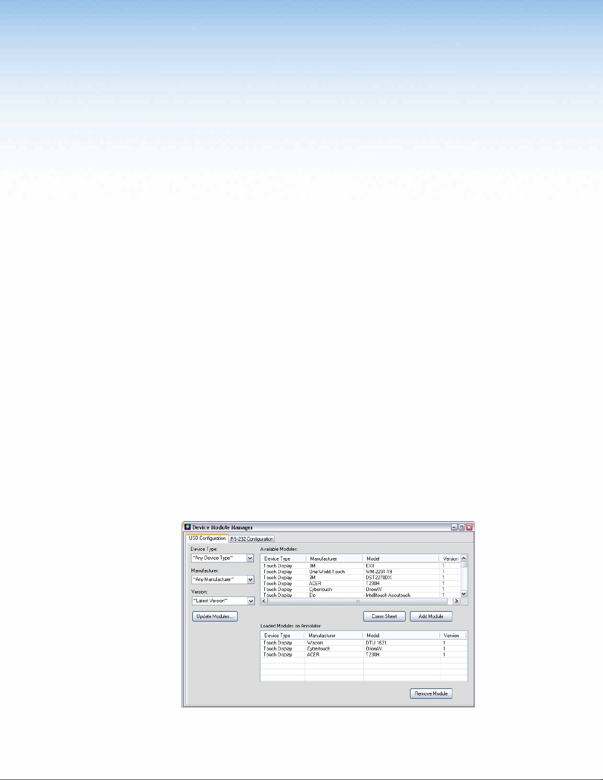
On Screen
Annotation
This section of the manual discusses on screen annotation and is in four sections:
• USB and RS-232 Driver Configuration
• USB Port Connections
• Touchscreen Calibration
• Annotation Overview
The Annotator is a high performance, hardware-based annotation processor for video and
computer-video sources. Annotating over motion video or still images is possible using
common touchscreen panels, and a standard keyboard and/or mouse. The touchscreen
panels can be connected by RS-232 or USB, and device drivers can be uploaded to ensure
compatibility with the Annotator. For a full list of compatible panels visit
www.extron.com. Contact Extron if the device you wish to use is not listed.
USB and RS-232 Driver Conguration
USB and RS-232 driver conguration is possible using the Signal Processing Products
Control Program. The Device Module Configuration option allows you to configure a
touchpanel so that it can be used with the Annotator.
Connect a touchpanel device to either of the USB ports or, using a NULL RS-232 cable
only, connecting the touchscreen to either of the two rear panel RS-232 ports.
USB Driver Conguration
To load a touchpanel driver:
1. Open the SPPCP program on a PC connected to the Annotator by an IP connection.
2. From the Tools menu, select Device Module Configuration.... This opens the
Device Module Manager window.
Figure 19. Device Module Manager Window
Annotator • On Screen Annotation 30
Page 37

3. Select the USB Configuration tab and sort by device type, manufacturer, and
version.
4. Click Update Modules to locate a device module in the Available Modules section
5. Select a module and click Add Module. The added module appears in the Loaded
Modules on Annotator section.
NOTE: Click Comm Sheet after selecting a device in the Available Modules section to
see communication information for the selected device driver.
To delete a touchpanel driver:
1. From the Tools menu, select Device Module Configuration.
2. In the Loaded Modules on Annotator section, select the device module to be deleted.
3. Click Remove Module. This removes the device module from the Annotator.
RS-232 Driver Conguration
To load a touchpanel driver:
4. Select the RS-232 Configuration tab. Sort by device type, manufacturer, and
version.
5. Click Update Modules to locate a device module in the Available Modules section
6. Click Load to Top Port or Load to Bottom Port to load the driver to the RS-232
port with the connected touchpanel.
To delete a touchpanel driver:
USB Port Connections
NOTE: Click Comm Sheet after selecting a device in the Available Modules section to
see communication information for the selected device driver.
1. From the Tools menu, select Device Module Configuration.
2. In the Loaded Modules on Annotator section, select the module to be deleted.
3. Click Remove Module. This removes the device module from the Annotator.
Touchpanels can be connected via the two rear panel USB ports. By connecting multiple
USB hubs (see gure 20), up to 20 devices can be connected.
A number of common touchpanels are automatically supported. A mix of size and vendor
types can be connected simultaneously, but unsupported devices may cause adverse
affects. For a full list of compatible panels visit www.extron.com.
The USB ports also support standard USB keyboards and mice.
Before use, panel calibration is advised (see ”Touchscreen Calibration” in this section).
Using a suitable USB A cable, connect a touchscreen device or hubs to the either of the
two USB A ports on the rear panel of the Annotator. Do not connect more than three
hubs in line (three deep).
Annotator
USB #1
1 2 3 4
Hubs
1 2 3 4
1 2 3 4
1 2 3 4 1 2 3 4
Figure 20. Connect USB Hubs for Multiple Devices
Annotator • On Screen Annotation 31
Page 38

Touchscreen Calibration
1
2
If a touchscreen is attached to the Annotator, the touch accuracy should be calibrated
using the Calibrate Panels setting in the Advanced configuration menu.
Both RS-232 and USB connected touchscreens require calibration.
To calibrate a connected and powered-on panel, do the following:
1. Press the Menu button on the front panel of the Annotator repeatedly until reaching
the Advanced Configuration menu.
2. Within the Advanced conguration menu press Next repeatedly to cycle to Calibrate
Panels Press Size.
3. Press Size and observe the touchpanel screen. A cross appears in the upper left corner.
4. Tap the screen at the cross, and the cross then moves to the top right corner.
5. Tap the cross in the top right corner. This moves the cross to the bottom right corner.
6. Tap the cross in the bottom right corner. This moves the cross to the bottom left
corner.
7. Tap the cross in the bottom left corner. The unit now saves the calibration data and
restarts the sequence.
8. Repeat the process for each connected touchscreen.
9. Press any Annotator front panel button to exit the sequence and save the data.
4
Figure 21. Sequence of Cross Positions for Setting the Touch Accuracy of a Screen
3
Annotator • On Screen Annotation 32
Page 39

Annotation Overview
The Annotator output has the capability to include a graphical tool bar which is used for
annotation. The tool bar can be enabled or disabled as desired. When enabled, the tool
bar is visible down the right side of the display and allows selection of the following:
Inputs selection, Pointer, Auto Image, Freehand, Line, Arrow, Rectangle, Ellipse, Text,
Highlighter, Size select, Eraser, Color, Fill, Undo, Redo, Clear, Tools - Capture, Freeze, Mute,
Whiteboard, Spotlight, Zoom, and Pan.
Figure 22. Annotation Menu Examples
When clicking on the tool bar arrow , the tool bar slides in from the right side, and
can be accessed through a touch screen, or by using a standard mouse and/or keyboard
attached to the rear PS/2 ports.
The tool bar disappears (hides) after a user-specified time-out.
If the time-out is set to zero, the tool bar remains on-screen indefinitely.
NOTE: All on screen annotations are lost when power to the Annotator is recycled.
Annotator • On Screen Annotation 33
Page 40

Default Annotation Buttons
Input selection — Selecting this button opens a pop-up palette
displaying the Annotator’s six inputs. Selecting any input button
switches the display to that input.
NOTE: A seventh input button (shown at right) is also
displayed if an optional HD-SDI input board is installed.
Pointer — Selecting this button changes the cursor to an
extra-large arrow of the currently selected color.
Auto-Image — On selection of this button, the unit performs an
auto image (automatic sizing, centering, and filtering to optimize
the output image on the currently selected input). A secondary button
appears to the left of the Auto Image button to confirm the action is desired.
Freehand — Selecting this button allows the user to draw freely on the
display screen.
NOTE: For Freehand, Line, Arrow, and Highlighter functions, the start point is
where the screen is touched (by finger or stylus), or where the cursor
starts when holding down the primary mouse button. The finish point
is where the stylus or finger is lifted from the screen, or at the point
where the mouse button is released.
For all drawn annotations, line color and weight are adjustable.
Line — Selecting this button allows the user to create a straight line
between two points.
Arrow — Selecting this button allows the user to create a straight line
between two points with an arrow at the end point.
Rectangle — Selecting this button allows the user to create a rectangle
with edges parallel to the raster.
between the primary and the opposite corners of a non-drawn rectangle.
a keyboard connected to the rear USB or PS/2 port. Text insertion
begins either at the mouse operated cursor point, or where the screen is
touched. If no insertion point is defined, then text is inserted at the
previous active function’s end point.
information, not the annotation.
NOTE: For Rectangle and Ellipse functions, the primary corner is where the
screen is first touched (by finger or stylus), or where the cursor starts
when holding down the primary mouse button. The opposite corner
is where the stylus or finger is lifted from the screen, or at the point
where the mouse button is released.
Unless the ll option is also selected, only the rectangle or ellipse
outline is drawn.
Ellipse — Selecting this button allows the user to create an ellipse
Text — Selecting this button allows the user to create on-screen text with
Highlighter — Selecting this button allows the user to highlight the video
Annotator • On Screen Annotation 34
Page 41

Size — Select this button to adjust size of text and/or line weight (not linked),
after selecting a drawing or text function, such as line, rectangle, or text.
A secondary palette opens displaying either line weight or text point size
depending on the active function. From the secondary palette select the desired
size button. Functions this applies to are Text, Line, Arrow, Freehand, Highlighter,
Arrows, Rectangle, Ellipse, and Eraser.
NOTE: Eraser and Highlighter size, text size, and line weight have discrete
size settings.
Eraser — Select this to erase any non saved annotations on the screen.
Color — Select this button to choose the color of any drawing function
(fill or outline), text, or pointer color. On selection, a secondary palette opens
with 16 color swatches. Select a color as desired. The active function now uses
the selected color.
Fill — Selecting this button in conjunction with selecting the rectangle or
ellipse button, allows the user to draw a solid shape filled with the currently
selected color.
NOTE: A drawn, unfilled shape cannot be filled afterwards, and vice versa.
Undo — Selecting this allows the user to undo the last 7 completed annotations
or undo a Clear action.
NOTE: A completed annotation is defined by lifting the finger or stylus from
the touchscreen, pressing the keyboard Enter key, or releasing the
primary mouse button.
Redo — If selected while using the Undo function, it recreates the last undone
annotation.
Clear — Selecting this clears the screen of all unsaved annotations, and can be
undone with the Undo function.
Tools — Selecting the Tools button opens a secondary palette containing the
following advanced tools: Capture, Freeze, Mute, Whiteboard, Spotlight, Zoom,
and Pan. On selection of any tool, the secondary palette closes. To reopen the
palette, click on the Tools button.
Capture — Select this to take a snapshot image of the current program output,
including annotations (but not any open On-Screen Display palettes).
This captured image can be saved to the Annotator memory for later recall.
NOTE: Using SIS commands the Capture tool can be customized to send out
an unsolicited response, indicating an image is ready to be streamed
directly to an external PC
Freeze — Select this to freeze the live video. To unfreeze the video, reselect this
button or switch inputs.
Mute — Select this to mute the video input and display a black screen.
Annotations and menus are still visible. To unmute the video, reselect
the Mute button, or select the Whiteboard tool, or switch inputs.
Annotator • On Screen Annotation 35
Page 42
Whiteboard — Select this to create a white canvas for annotations. No
input video image is visible. To remove the white canvas, reselect the
Whiteboard button, select mute, or switch inputs.
Spotlight — Select this to create an ellipse to focus on a specific area of
the screen, while the outer area’s brightness is greatly reduced. The
shape and size of the ellipse is adjustable by dragging the cursor while
outside of it, to any point. The ellipse can be moved to any point by
dragging the cursor while within the ellipse.
Zoom — Select this to zoom in to a specic area of the screen. Using the
cursor, create a rectangle at the desired area and the Annotator zooms in
to view that area. If the boundaries of the area are beyond the zoom
capabilities, then the view will not change. To zoom out draw a small
rectangle (<100 pixels, ~1 inch x 1 inch) and the normal view is restored.
Pan — Selecting this while in zoom mode, allows the user to move the
focus to a new area. Place the cursor on a zoomed image and drag to
the desired area
\
Annotator • On Screen Annotation 36
Page 43

SIS Communication and Control
The Annotator can be operated and configured using Simple Instruction Set (SIS)
commands input via a PC connected to either of the processor’s serial ports or the
Ethernet port. See o and p on pages 8 and 10, and “Ethernet Connection” section
for wiring details.
RS-232/RS-422 Link
The Annotator has two rear ports and one front port that can be used for serial control.
All ports enable use of SIS commands and the Windows-based control software. The
default protocol for these ports is:
• 9600 baud • 1 stop bit • no parity • no ow control • 8 data bits.
NOTE: The lower rear panel RS-232 port is designated as Comm1, the upper port is
Comm 3, and the front panel config port is Comm 2.
See
on page 10 for connection details.
p
Ethernet Connection
Ethernet (LAN) Port
The rear panel Ethernet connector on the unit can be connected to an Ethernet LAN or
WAN. Communications between the unit and the controlling device is via Telnet (a TCP
socket using port 23). The TCP port can be changed if necessary. This connection makes
SIS control of the unit possible using a computer connected to the same LAN or WAN. The
SIS commands and behavior of the unit are identical to that when communicating to it via
RS-232.
Ethernet Cabling
The Ethernet cable can be terminated as a straight-through cable or a crossover cable and
must be properly terminated for your application. See “Ethernet Connection” section for
cable termination details.
Default IP Addresses
To access the Annotator via the Ethernet port, you need the Extron IP address and may
need the subnet mask and the gateway address. If the IP address has been changed to
an address comprised of words and characters, the actual numeric IP address can be
determined using the ping (ICMP) utility (see “Ethernet Connection” section for more
details). If the addresses have not been changed, the factory-specied defaults are:
IP address: 192.168.254.254, subnet mask: 255.255.0.0, gateway address: 0.0.0.0
Annotator • SIS Communication and Control 37
Page 44

Establishing a Connection
Establish a network connection to the processor as follows:
1. Open a TCP socket to port 23 using the processor’s IP address.
NOTE: If the local system administrators have not changed the value, the factory-
specied default, 192.168.254.254, is the correct value for this eld.
The processor responds with a copyright message including the date, the name of the
product, firmware version, part number, and the current date/time.
NOTE: • If the processor is not password-protected, the device is ready to accept SIS
commands immediately after it sends the copyright message.
• If the processor is password-protected, a password prompt appears below
the copyright message.
2. If the processor is password protected, enter the appropriate administrator or user
password.
• If the password is accepted, the processor responds with Login User or
Login Administrator.
• If the password is not accepted, the Password prompt reappears
Connection Time-outs
The Ethernet link times out after a designated period of time of no communications. By
default, this time-out value is set to five minutes but the value can be changed.
NOTE: Extron recommends leaving the default time-out at ve minutes and
periodically issuing the Query (Q) command to keep the connection active. If
there are long idle periods, Extron recommends disconnecting the socket and
reopening the connection when another command must be sent.
Number of Connections
The Annotator can have up to 200 simultaneous TCP connections, including all HTTP
sockets and Telnet connections. When the connection limit is reached, the processor
accepts no new connections until some have been closed. No error message or indication
is given that the connection limit has been reached. To maximize performance of an IP Link
device, the number of connections should stay low and unnecessary open sockets should
be closed.
Using Verbose Mode
Telnet connections to the processor can be used to monitor for changes that occur on the
processor, such as front panel operations and SIS commands from other Telnet sockets or
a serial port. For a Telnet session to receive change notices from the processor, the Telnet
session must be in verbose mode 1 or 3. In verbose mode 1 or 3, the Telnet socket reports
changes in messages that resemble SIS command responses.
Host-to-Processor Instructions
SIS commands consist of one or more characters per command eld. They do not require
any special characters to begin or end the command character sequence. Each processor
response to an SIS command ends with a carriage return and a line feed (CR/LF = ]),
which signals the end of the response character string. A string is one or more characters.
Annotator • SIS Communication and Control 38
Page 45

Processor-Initiated Messages
When a local event such as a front panel operation occurs, the processor responds by
sending a message to the host. The processor-initiated messages are listed below.
With an RS-232/422 connection (upon power up):
(c) Copyright 2009, Extron Electronics Annotator, Vx.xx, 60-968-14]
With an Internet connection:
(c) Copyright 2009, Extron Electronics Annotator, Vx.xx, 60-968-14]
Ddd, DD MMM YYYY HH:MM:SS (day, date time. for example. Tue, 14 Apr 2009
14:43:17)
The processor initiates the copyright message when powered on or when connection via
Internet protocol (IP) is established. Vx.xx is the firmware version number.
]Password:
The processor initiates the password message immediately after the copyright message
when the controlling system is connected using TCP/IP or Telnet and the processor is
password protected. The processor requires an administrator or user level password before
performing the commands entered.
NOTE: Password prompt is re-displayed if an incorrect password is entered.
]Login Administrator] and ]Login User]
The processor initiates the login message when a correct administrator or user password
has been entered. If the user and administrator passwords are the same, the processor
defaults to administrator privileges.
Reconfig]
The processor sends the Reconfig message whenever a new resolution is applied.
NOTE: Response is seen via RS-232 connection only.
Exen]
The processor initiates the Exe message when executive mode is toggled on or off from
the front panel. “n” is the executive mode status: 1 = on, 0 = off.
Processor Error Responses
When the Annotator receives an SIS command and determines that it is valid, it performs
the command and sends a response to the host device. If the processor is unable to
perform the command because the command is invalid or contains invalid parameters, the
processor returns an error response to the host. The error response codes are:
E01 — Invalid input channel number (out of range)
E10 — Invalid command
E11 — Invalid preset number
E12 — Invalid output number/port number
E13 — Invalid parameter (out of range)
E14 — Command not available for this conguration
E17 — Invalid command for this signal type
E22 — Busy
E24 — Privilege violation
E25 — Device not present
E26 — Maximum number of connections exceeded
E27 — Invalid event number
E28 — Bad lename/le not found
Annotator • SIS Communication and Control 39
Page 46
Using the Command/Response Table for SIS Commands
The command/response table follows this section. Lowercase letters are acceptable in
the command eld except where indicated. The table below shows the hexadecimal
equivalent of ASCII characters used in the command/response tables.
ASCII to HEX Conversion Table
space
Figure 23. ASCII to Hexadecimal Conversion
Symbols are used throughout the table to represent variables in the command/response
elds. Command and response examples are shown throughout the table.
Symbol Definitions
] = Carriage return with line feed
} = Carriage return with no line feed
¦ or
• = Space
•
E or W = Escape key
NOTE: If unit does not support or recognize the entered commands, nothing will
happen and no response is issued..
X! = Input selection, 1 to 7
X@ = Output selection:
0 = All outputs (default)
1 = Program only (BNC, MTP, optional output card)
2 = Preview only (VGA)
3 = None
X# = Input video format:
1 = RGB (default) 6 = Composite video
2 = YUVp/HDTV 7 = SDI
3 = RGBcvS 8 = HD-SDI
4 = YUVi 9 = DVI
5 = S-video 10 = Auto detect
X$ = H/V start — 0 to 255 (default midpoint = 128)
X^ = Pixel phase — 0 to 31 (default = 16)
X& = Total pixels — (±512 of the default value)
X* = Active pixels — (±512 of the default value)
X( = Active lines — (±512 of the default value)
X1) = Off/disable (0) or on/enable (1)
X1! = Input standard:
0 = No signal 4 = SECAM
1 = NTSC - = N/A (when input is set to a high resolution signal format)
2 = PAL
Annotator • SIS Communication and Control 40
Page 47

X1@ = Internal temperature (in degrees Celsius)
X1# = Horizontal and vertical frequencies (format is three digit with single decimal
and leading zeros for example, 075.3)
X1$ = Disable (0), or enabled mode 1 (1) or enabled mode 2 (2)
X1% = Picture adjustment — 0 to 127 (default 64)
X1^ = H or V position (zero location is 2048, and limits are ± the output resolution)
X1& = H or V size (0 to 200% of the output area, in single pixel increments)
X1* = Zoom (100 to 500%)
Default for low resolution video = 111%
Default for high resolution video = 100%
X1( = Pan — 0 to 200 (default = 100, center point)
X2) = Test patterns:
0 = off (default) 8 = Crop 7 = white eld
1 = color bars 9 = 1.33 aspect ratio
2 = crosshatch 10 = 1.78 aspect ratio
3 = 4x4 crosshatch 11 = 1.85 aspect ratio
4 = grayscale 12 = 2.35 aspect ratio
5 = ramp 13 = safe area
6 = alternating pixels 14 = blue mode
X2! = Scaler resolution:
1 = 640x480 14 = 1365x1024
2 = 800x600 15 = 1440x900
3 = 852x480 16 = 1400x1050
4 = 1024x768 17 = 1680x1050
5 = 1024x852 18 = 1600x1200
6 = 1024x1024 19 = 1920x1200
7 = 1280x768 20 = 480p
8 = 1280x800 21 = 576p
9 = 1280x1024 22 = 720p
10 = 1360x765 23 = 1080i
11 = 1360x768 24 = 1080p
12 = 1365x768 25 = 2048x1080
13 = 1366x768 26 = 1080p CVT
X2@ = Output refresh rate:
1 = 23.98 Hz 6 = 50 Hz
2 = 24 Hz 7 = 59.94 Hz
3 = 25 Hz 8 = 60 Hz (default)
4 = 29.97 Hz 9 = 75 Hz
5 = 30 Hz
X2# = Output polarity:
0 = H-/V- (default)
1 = H-/V+
2 = H+/V 3 = H+/V+
X2$ = Output sync format:
0 = RGBHV (default)
1 = RGsB
2 = YUV bi-level
3 = YUV tri-level
Annotator • SIS Communication and Control 41
Page 48

X2% = User presets — 1 to 16
X2^ = Input presets — 1 to 128
X2* = On-screen menu time-out — 1 to 64, in 1 second increments,
0 = always displayed (default = 10)
X3& = RGB delay — 0 to 50, in 0.1 second increments (default is 05 = 0.5 seconds)
X4) = Video mute — 01 = mute to black, 02 = mute to white,
00 = unmute (restore image)
X5) = Annotation type:
0 = eraser 7 = rectangle
1 = pointer 8 = text tool
2 = freehand 9 = spotlight
3 = highlighter 10 = zoom tool
4 = vector line 11 = pan tool
5 = arrow line (arrow appears at the endpoint of the vector)
6 = ellipse
X5! = Font selection — 16 character le name including *.FNT extension,
0 = default font (Arial)
X5@ = Font size — 8 to 63 point font (default = 8 pt)
X5# = Line color — 6 bit RGB, 64 total colors
000000 = Black
010000 = Dark red (33%)
100000 = Medium red (66%)
110000 = Bright red (100%)
001100 = Bright green (66%)
000011 = Bright blue (default)
111111 = White
010101 = Dark gray (33%)
Format:
011011
Red
Value
Green
Value
Blue
Value
X5$ = Line weight, eraser, or highlighter width — 1 to 63 pixels wide (default = 8)
X5% = Aspect ratio 1 = Follow, 2 = Fill
X5^ = On-screen clock:
0 = disabled (default)
1 = date and time
2 = time only
3 = date only
X5& = Annotation coordinates — 8 digit number with rst four being the X coordinate,
the last four the Y coordinate, limits = 1000,1000. Fixed for any output rate.
Example, (0,0) = 00000000 = top left; (500,500) = 05000500 = screen center.
X7% = Scan converter output format
0 = S-video/composite video
1 = YUVi
2 = RGsB
X7^ = Scan converter output standard
0 = NTSC
1 = PAL
X7& = Scan converter lter level (encoder, horizontal, icker) — 0 to 3
Annotator • SIS Communication and Control 42
Page 49

Command ASCII command
(host to processor)
Input Switching and Configuration
Input selection
Response
(processor to host)
Additional description
Select input
View current input
Input video format
Set format
View format
View detected format
Input EDID
Specify an EDID value
View EDID value
X!! InX!] Select video from input X!.
!
X!*X#\ TypX!*X#] Set input X! to video format X#.
X!\ X#] View video format of input X!.
X!*\ AtypX!*X#]
EX2!*X2@EDID
EEDID} X2!*X2@]
NOTE: Default is to match output: X2!=0 X2@=0
Auto image
Enable auto image
Disable auto image
Execute auto image
View auto image
Horizontal start
Specify a value
Increment value
Decrement value
View value
Vertical start
Specify a value
Increment value
Decrement value
View value
X!*1A ImgX!*1] Auto image input X! when selected.
X!*0A ImgX!*0] Turn off auto image for input X!.
A
X!A X1)]
EX$HSRT} HsrtX!*X$]
E+HSRT} HsrtX!*X$]
E-HSRT} HsrtX!*X$]
EHSRT} X$]
EX$VSRT} VsrtX!*X$]
E+VSRT} VsrtX!*X$]
E-VSRT} VsrtX!*X$]
EVSRT} X$]
}
X!]
EdidX2!*X2@]
]
Img
View currently selected input source.
View actual video format auto
detected on input
Set EDID resolution and refresh for
DVI and VGA inputs.
View EDID resolution and refresh for
DVI and VGA inputs.
Execute auto image for current input.
View auto image setting.
Set horizontal location of rst active
pixel in active input.
Increase value.
Decrease value.
Show horizontal location of rst
active pixel in active input.
Set vertical location of first active line
in active input.
Increase value.
Decrease value.
Show vertical location of first active
line in active input.
X!.
NOTE: X! = Input selection; 1 – 7
X# = Input video format; 1 = RGB (default), 2 = YUVp/HDTV, 3 = RGBcvS, 4 = YUVi, 5 = S-video,
6 = Composite video, 7 = SDI, 8 = HD-SDI, 9 = DVI, 10 = Auto detect
X$ = H/V start; 0 to 255 (default midpoint = 128)
X2! = Scaler resolution; 1 = 640x480, 2 = 800x600, 3 = 852x480, 4 = 1024x768, 5 = 1024x852,
6 = 1024x1024, 7 = 1280x768, 8 = 1280x800, 9 = 1280x1024, 10 = 1360x765,
11 = 1360x768, 12 = 1365x768, 13 = 1366x768, 14 = 1365x1024, 15 = 1440x900,
16 = 1400x1050, 17 = 1680x1050, 18 = 1600x1200, 19 = 1920x1200, 20 = 480p,
21 = 576p, 22 = 720p, 23 = 1080i, 24 = 1080p, 25 = 2048x1080, 26 = 1080p CVT
X2@ = Output refresh rate; 1 = 23.98 Hz, 2 = 24 Hz, 3 = 25 Hz, 4 = 29.97 Hz, 5 = 30 Hz, 6 = 50 Hz.
7 = 59.94 Hz, 8 = 60 Hz (default), 9 = 75 Hz.
Annotator • SIS Communication and Control 43
Page 50

Command/Response Table for SIS Commands
Command ASCII command
Pixel phase
Specify a value
Increment value
Decrement value
View value
Total pixels (RGB and YUVp/HDTV only)
Specify a value
Increment value
Decrement value
View value
Active pixels
Specify a value
Increment value
Decrement value
View value
(host to processor)
EX^PHAS} PhasX!*X^]
E+PHAS} PhasX!*X^]
E-PHAS} PhasX!*X^]
EPHAS} X^]
EX&TPIX} TpixX!*X&]
E+TPIX} TpixX!*X&]
E-TPIX} TpixX!*X&]
ETPIX} X&]
EX*APIX} ApixX!*X*]
E+APIX} ApixX!*X*]
E-APIX} ApixX!*X*]
EAPIX} X*]
Active lines
Specify a value
Increment value
Decrement value
View value
EX(ALIN} AlinX!*X(]
E+ALIN} AlinX!*X(]
E-ALIN} AlinX!*X(]
EALIN} X(]
Response
(processor to host)
Additional description
Set pixel phase to specied value for
active input.
Increase value.
Decrease value.
Show pixel phase.
Set total pixels to specied value for
active input.
Increase value.
Decrease value.
Show total pixels.
Set active pixels to specied value for
active input.
Increase value.
Decrease value.
Show active pixels.
Set active lines to specified value for
active input.
Increase value.
Decrease value.
Show active lines.
3:2/2:2 Film mode detect
Enable film mode
Disable lm mode
View setting
EX!*1FILM} FilmX!*X1)]
EX!*0FILM} FilmX!*X1)]
EX!FILM} X1)]
NOTE: X! = Input selection; 1 – 7
X^
= Pixel phase; 0-31 (default = 16)
X&
= Total pixels; (±512 of the default value)
X*
= Active pixels; (±512 of the default value)
X(
= Active lines; (±512 of the default value)
X1)
= 0 (off/disable), 1 (on/enable)
Turn film mode detection on.
Turn film mode detection off.
View setting.
Annotator • SIS Communication and Control 44
Page 51

Command ASCII command
(host to processor)
Picture Adjustments
Video mute
Mute video to black
Mute video to white
Unmute video
View mode
Freeze
Enable
Disable
View
Color
Specify a value
Increment value
Decrement value
View value
Tint
Specify a value
Increment value
Decrement value
View value
1B
2B
0B
B
1F
0F
F
EX1%COLR} ColrX!*X1%]
E+COLR} ColrX!*X1%]
E-COLR} ColrX!*X1%]
ECOLR} X1%]
EX1%TINT} TintX!*X1%]
E+TINT} TintX!*X1%]
E-TINT} TintX!*X1%]
ETINT} X1%]
Response
(processor to host)
]
Vmt1
Vmt2
]
Vmt0
]
X4)]
]
Frz1
]
Frz0
X1)]
Additional description
Mute video and display a black
screen.
Mute video and display a white
screen.
Restore picture.
Mute status is
Freeze selected input.
Unfreeze selected input.
Freeze status is
Set color level to
Increase value.
Decrease value.
Show color level.
Set tint level to
Increase value.
Decrease value.
Show tint level.
X4).
X1)
X1%
X1%
.
.
.
Contrast
Specify a value
Increment value
Decrement value
View value
Brightness
Specify a value
Increment value
Decrement value
View value
Detail filter
Specify a value
Increment value
Decrement value
View value
EX1%CONT} ContX!*X1%]
E+CONT} ContX!*X1%]
E-CONT} ContX!*X1%]
ECONT} X1%]
EX1%BRIT} BritX!*X1%]
E+BRIT} BritX!*X1%]
E-BRIT} BritX!*X1%]
EBRIT} X1%]
EX1%HDET} HdetX!*X1%]
E+HDET} HdetX!*X1%]
E-HDET} HdetX!*X1%]
EHDET} X1%]
NOTE: X! = Input selection; 1 – 7
X1)
= 0 (off/disable), 1 (on/enable)
X1% = Picture adjustment; 0 to 127 (default 64)
X4)
= 00 (none), 01 (black), or 02 (white)
Set contrast level to
Increase value.
Decrease value.
Show contrast level.
Set brightness level to
Increase value.
Decrease value.
Show brightness level.
Set detail level to
Increase value.
Decrease value.
Show detail level.
X1%
X1%
.
.
X1%
.
Annotator • SIS Communication and Control 45
Page 52

Command ASCII command
Horizontal shift
Specify a value
Increment value
Decrement value
View value
Vertical shift
Specify a value
Increment value
Decrement value
View value
Horizontal size
Specify a value
Increment value
Decrement value
View value
Vertical size
Specify a value
Increment value
Decrement value
View value
(host to processor)
EX1^HCTR} HctrX!*X1^]
E+HCTR} HctrX!*X1^]
E-HCTR} HctrX!*X1^]
EHCTR} X1^]
EX1^VCTR} VctrX!*X1^]
E+VCTR} VctrX!*X1^]
E-VCTR} VctrX!*X1^]
EVCTR} X1^]
EX1&HSIZ} HsizX!*X1&]
E+HSIZ} HsizX!*X1&]
E-HSIZ} Hsiz
EHSIZ} X1&]
EX1&VSIZ} Vsiz
E+VSIZ}
E-VSIZ}
EVSIZ}
Response
(processor to host)
X!
*X1&]
X!
*X1&]
VsizX!*
VsizX!*
X1&]
X1&]
X1&]
Additional description
X1&
X1^
X1&
.
X1^
.
.
Set horizontal position to
Shift position right.
Shift image left.
Show horizontal position value.
Set vertical position to
Shift image down.
Shift image up.
Show vertical position value.
Set horizontal size to
Widen the image.
Make image narrower.
Show horizontal size value.
Set vertical size to
Make the image taller.
Make image shorter.
Show vertical size value.
.
Zoom
Specify a value
Increment value
Decrement value
View value
Pan
Specify a horizontal value
Pan left
Pan right
Specify a vertical value
Pan down
Pan up
EX1*ZOOM} ZoomX!*X1*]
E+ZOOM} ZoomX!*X1*]
E-ZOOM} ZoomX!*X1*]
EZOOM} X1*]
EX1(HPAN} HpanX!*X1(]
E+HPAN} HpanX!*X1(]
E-HPAN} HpanX!*X1(]
EX1(VPAN} VpanX!*X1(]
E+VPAN} VpanX!*X1(]
E-VPAN} VpanX!*X1(]
NOTE: X! = Input selection; 1 – 7
X1^ = H and V position; zero location is 2048, and limits are ± the output resolution
X1& = H and V size (0 to 200% of the output area in single pixel increments)
X1* = Zoom, 100 to 500%; default for low resolution video = 111%, default for high resolution video = 100%)
X1( = Pan, 0 to 200 (default = 100, center point)
Set zoom percentage to
Zoom in.
Zoom out.
Show zoom percentage.
Set horizontal pan value to
Pan left.
Pan right.
Set vertical pan value to
Pan down.
Pan up.
X1*
X1(
.
X1(
.
.
Annotator • SIS Communication and Control 46
Page 53

Command ASCII command
(host to processor)
Output Configuration
Output scaler rate
Set output rate
View output rate
Output polarity
Set polarity
View polarity setting
Output sync format
Set format
View sync setting
EX2!*X2@RATE} RateX2!*X2@]
ERATE} X2!*X2@]
EX2#OPOL} OpolX2#]
EOPOL} X2#]
EX2$OSYN} OsynX2$]
EOSYN} X2$]
Scan Converter Board
Video output format
Set output format
View output format
Video output standard
Set output standard
View output standard
EX7%VTPO} VtpoX7%]
EVTPO} X7%]
EX7^VSTD} VstdX7^]
EVSTD} X7^]
Response
(processor to host)
Additional description
Select output resolution and refresh
rate.
Show selected output rate.
Set polarity for RGBHV ouput.
Show current output polarity.
Set output sync format.
Show current output sync format.
Select video output format to
View setting.
Select video output standard to
View setting.
X7%
.
X7^
.
Scan converter horizontal position
Specific value
Increment up
Increment down
View
Scan converter vertical position
Specific value
Increment up
Increment down
View
ESX1^HCTR} HctrSX1^]
ES+HCTR} HctrSX1^]
ES-HCTR} HctrSX1^]
ESHCTR} X1^]
ESX1^VCTR} VctrSX1^]
ES+VCTR} VctrSX1^]
ES-VCTR} VctrSX1^]
ESVCTR} X1^]
Set horizontal position to
Shift image right.
Shift image left.
Horizontal position value is
Set vertical position to
Shift image down.
Shift image up.
Vertical position value is
NOTE: X1^ = H and V position; zero location is 2048, and limits are ± the output resolution
X2! = Scaler resolution;1 = 640x480, 2 = 800x600, 3 = 852x480, 4 = 1024x768, 5 = 1024x852,
6 = 1024x1024, 7 = 1280x768, 8 = 1280x800, 9 = 1280x1024, 10 = 1360x765,
11 = 1360x768, 12 = 1365x768, 13 = 1366x768, 14 = 1365x1024, 15 = 1440x900,
16 = 1400x1050, 17 = 1680x1050, 18 = 1600x1200, 19 = 1920x1200, 20 = 480p,
21 = 576p, 22 = 720p, 23 = 1080i, 24 = 1080p, 25 = 2048x1080, 26 = 1080p CVT
X2@ = Output refresh rate; 1 = 23.98 Hz, 2 = 24 Hz, 3 = 25 Hz, 4 = 29.97 Hz, 5 = 30 Hz, 6 = 50 Hz.
7 = 59.94 Hz, 8 = 60 Hz (default), 9 = 75 Hz
X2# = Output polarity; 0 = H-/V- (default), 1 = H-/V+, 2= H+/V-, 3 = H+/V+
X2$ = Output sync format; 0 = RGBHV (default), 1 = RGsB, 2= YUV bi-level, 3 = YUV tri-level
X7% = Scan converter output format, 0 = S-video/composite video, 1 = YUVi, 2 = RGsB
X7^ = Scan converter output standard, 0 = NTSC, 1 = PAL
X1^
X1^
X1^
.
X1^
.
.
.
Annotator • SIS Communication and Control 47
Page 54

Command ASCII command
Scan converter horizontal size
Specific value
Increase size
Decrease size
View
Scan converter vertical size
Specific value
Increase size
Decrease size
View
Scan converter horizontal filter
Set detail level
Increment up
Increment down
View detail value
Scan converter flicker filter
Set icker lter level
Increment up
Increment down
View icker lter level
(host to processor)
ESX1&HSIZ} HsizSX1&]
ES+HSIZ} HsizSX1&]
ES-HSIZ} HsizSX1&]
ESHSIZ} X1&]
ESX1&VSIZ} VsizSX1&]
ES+VSIZ} VsizSX1&]
ES-VSIZ} VsizSX1&]
ESVSIZ} X1&]
ESX7&HDET} HdetSX7&]
ES+HDET} HdetSX7&]
ES-HDET} HdetSX7&]
ESHDET} X7&]
X7&
ES
VDET} VdetSX7&]
ES+VDET} VdetSX7&]
ES-VDET} VdetSX7&]
ESVDET}
Response
(processor to host)
X7&]
Additional description
X1&
X7&
X1&
X1&
.
.
X7&
X1&
.
.
.
.
Set horizontal size to
Widen image.
Make image narrower.
Horizontal size is
Set vertical size to
Make image taller.
Make image shorter.
Vertical size is
Set H lter level to
Increase H lter level.
Decrease H lter level.
H lter level is
Specify the icker lter level to X7&.
Increase the icker lter level.
Decrease the icker lter level.
View the icker lter level.
Scan converter encoder filter
Set encoder filter level
View
ES
EVENC}
Presets
User presets
Recall presets
Save presets
Input presets
Recall presets
Save presets
Auto Memory
Enable
Disable
View setting
X2%. 1RprX2%
1*
1*
X2%, 1SprX2%
X2^
2*
X2^
2*
E
1AMEM}
E0AMEM} Amem0]
EAMEM} X1)]
NOTE: X1) = off/disable (0), on/enable (1)
X1& = H and V size, 0 to 200% of the output area in single pixel increments
X2% = Memory presets 1 to 16
X2^ = Input presets 1 to 128
= Filter level, 0 to 3
X7&
X7&
VENC}
VencS
X7&]
. 2RprX2^
, 2SprX2^
Amem1
X7&]
]
]
]
]
]
Set video encoder filter level to X7&
View the encoder filter level.
Recalls user preset
input.
Saves user preset
input.
Recalls input preset
Saves input parameters to preset
Set auto memory on. Previous
settings for incoming signal are auto
recalled.
Set auto memory off. Default settings
are always used unless input preset is
recalled manually.
View auto memory status.
X2%
X2%
for selected
X2^
for selected
.
.
X2^
.
Annotator • SIS Communication and Control 48
Page 55

Command ASCII command
(host to processor)
Aux Scaler Board
Output scaler rate
Response
(processor to host)
Additional description
Set output rate
View output rate
Output sync polarity
Set polarity
View polarity setting
Output sync format
Set format
View sync setting
Aspect Ratio mode
Enable Fill mode
Enable Follow mode
View aspect ratio setting
Detail filter
Set detail level
Increment up
Increment down
View detail value
EXX2!*X2@Rate} RateXX2!*X2@]
EXRate} X2!*X2@]
EXX2#OPOL} OpolXX2#]
EXOPOL} X2#]
EXX2$OSYN} OsynXX2$]
EXOSYN} X2$]
EX1Aspr} AsprX1]
EX2Aspr} AsprX2]
EXAspr} X5%]
EXX1%HDET} HdetXX1%]
EX+HDET} HdetXX1%]
EX–HDET} HdetXX1%]
EXHDET} X1%]
Select output resolution and refresh
rate.
Show selected output rate.
Set polarity for scaler ouput.
Show current output polarity.
Set output sync format.
Show current output sync format.
Set aspect ratio to Fill.
Set aspect ratio to Follow (default).
Show current aspect ratio.
Specify the detail (sharpness) level
to X1%.
Increase the detail level.
Decrease the detail level.
Show the detail setting.
Test pattern
NOTE: Test pattern on aux scaler board are color bars, 4x4 crosshatch, grayscale, ramp, alternating pixels, and crop.
Set the test pattern
View test pattern
NOTE: X1%
= Detail lter level, 0 to 127
X2) = Test patterns for Scaler board: 0 = Off (default), 1 = Color bars, 2 = Crosshatch, 3 = 4x4 Crosshatch,
4 = Grayscale, 5 = Ramp, 6 = Alternating Pixels, 8 = Crop
X2! = Aux scaler resolution,
1 = 640x480 8 = 1280x1024 14 = 1600x1200 20 = 1440x900
2 = 800x600 9 = 1360x765 15 = 480p 21 = 1680x1050
3 = 852x480 10 = 1365x768 16 = 576p 22 = 1280x800
4 = 1024x768 11 = 1365x1024 17 = 720p 23 = 1080p Sharp
5 = 1024x852 12 = 1366x768 18 = 1080i 24 = 1920x1200
6 = 1024x1024 13 = 1400x1050 19 = 1080p 25 =1080p CVT
7 = 1280x768
X2@ = Aux scaler refresh rate,
4 = 96 Hz, 5 = 100 Hz, 6 = 120 Hz, 7 = 59.94 Hz
X2# = Output polarity; 0 = H-/V- (default), 1 = H-/V+, 2= H+/V-, 3 = H+/V+
X2$ = Aux scaler output sync format, 0 = RGBHV, 1 = RGsB, 2 = YUV bi-level, 3= YUV tri-level
X5% = Aspect ratio, 1 = Follow, 2 = Fill
EXTestX2)} TestXX2)] Set test pattern to X2).
EXTest} X2)]
1 = 50 Hz, 2 = 60 Hz, 3 = 72 Hz (75 Hz for 1440x900, 24 Hz for 1080p),
View the test pattern.
Annotator • SIS Communication and Control 49
Page 56

Command ASCII command
(host to processor)
Advanced Configurations
Test pattern
Set test pattern
View test pattern
EX2)TEST} TestX2)]
ETEST} X2)]
RGB delay time
Set value
View setting
EX3&VDLY} VdlyX3&]
EVDLY} X3&]
Switch effect
Cut
Fade
View setting
E0SWEF
E1SWEF} Swef1]
ESWEF} 0] (or 1])
}
Aspect Ratio mode
Enable Fill mode
Enable Follow mode
View aspect ratio setting
E1Aspr} Aspr1]
E2Aspr} Aspr2]
EAspr} X5%]
MTP Pre-peaking
Enable
Disable
E1OPEK} Opek1]
E0OPEK} Opek0]
Response
(processor to host)
Swef0]
Additional description
Select test pattern
View which test pattern is used.
Set RGB delay.
View RGB delay setting.
Sets the switch effect to cut.
Sets the switch effect to fade
through to black.
View effect setting.
Set aspect ratio to Fill.
Set aspect ratio to Follow (default).
Show current aspect ratio
Enables pre-peaking on the MTP
output.
Disables pre-peaking.
X2)
.
View setting
EOPEK} X1)]
View pre-peaking setting.
Front panel lockout (executive mode)
Enable Mode 1
Enable Mode 2
Disable
View front panel lock status
1X
2X
0X
X
Exe1
Exe2
Exe0
X1$]
]
]
]
Limited front panel adjustments.
Lock out entire front panel.
Adjustments and selections can be
made from front panel.
Show executive mode status.
NOTE: For full lock mode details see the “Setting the Front Panel Locks (Executive Modes)” section.
Picture in Picture
PIP on/off
PIP on
PIP off
View PIP status
EX!PIP} PipX!]
E0PIP} Pip0]
EPIP} X!]
Turn PIP on and display input X!.
Turn PIP off.
View PIP window selection.
NOTE: When PIP is enabled, all picture control commands apply to the image in the PIP window.
Swap PIP
Swap
%
Tke
]
Swap PIP/main window content.
NOTE: X! = Input selection 1 – 7
X1) = off/disable (0), on/enable (1)
X1$ = Disabled (0), or enabled mode 1 (1) or enabled mode 2 (2)
X2) = Test patterns: 0 = Off (default), 1 = Color bars, 2 = Crosshatch, 3 = 4x4 Crosshatch, 4 = Grayscale,
5 = Ramp, 6 = Alternating Pixels, 7 = White eld 8 = Crop, 9 = 1.33 Aspect ratio,
10 = 1.78 Aspect ratio, 11 = 1.85 Aspect ratio, 12 = 2.35 Aspect ratio, 13 = Safe area, 14 = Blue mode
X3& = RGB delay — 0 to 50, in 0.1 second increments (default is 05 = 0.5 seconds)
X5% = Aspect ratio, 1 = Follow, 2 = Fill
Annotator • SIS Communication and Control 50
Page 57

Command ASCII command
(host to processor)
Response
(processor to host)
Additional description
Annotation
Annotation type
Set type
View type
EX5)DRAW} DrawX5)]
EDRAW} DrawX5)]
Sets current annotation to
View current annotation type.
Annotation coordinates
Location
Complete annotation
EX5&APNT}
EASTP} Astp]
(no response)
Places the annotation location at
Indicates the end of an annotation
function.
NOTE: All coordinate values sent to the Annotator are interpreted according to the guidelines for the current
annotation type.
Example: Draw a square
Esc 00000000APNT } Esc 00100010APNT } Esc 00200020APNT } Esc 00300030APNT } Esc ASTP }
Annotation color
Set color
View color
EX5#ACOL} AcolX5#]
EACOL} X5#]
Sets the color to
View current annotation color.
NOTE: The color setting applies to all annotations.
Annotation object fill
Enable object fill
Disable object ll
View setting
E1FILL} Fill1]
E0FILL} Fill0]
EFILL} X1)]
Enable fill for new objects drawn.
Disable ll for new objects drawn.
View current fill setting.
X5#
X5)
.
X5&
.
.
NOTE: The fill setting applies to rectangles and ellipses drawn after the setting has been modified.
Text configuration
Set text font
View font
EX5!FONT} FontX5!]
EFONT} X5!]
Set annotation font to
View current font file name.
NOTE: Font les must be stored on the hardware in the nortxe-font folder.
Set text size
View text size
EX5@TXSZ} TxszX5@]
ETXSZ} X5@]
Set annotation text size to
View current text size.
Line configuration
Set line weight
View size
NOTE:
EX5$LNWT} LnwtX5$]
ELNWT} X5$]
X1)
= off/disable (0), on/enable (1)
X5)
= Annotation type: 0 = Eraser, 1 = Pointer, 2 = Freehand, 3 = Highlighter, 4 = Vector line, 5 = Arrow
line (arrow at the endpoint of the vector), 6 = Ellipse, 7 = Rectangle, 8 = Text tool, 9 = Spotlight,
10 = Zoom tool,11 = Pan tool
X5!
= Font selection; 16 character le name including *.FNT extension, 0 = default font (Arial)
X5@
= Font size; 8 to 63 point font (default = 8 pt)
X5#
= Line color; 6 bit RGB, 64 total colors, e.g. 000000 = black, 010000 = dark red (33%),
100000 = medium red (66%), 110000 = bright red (100%), 001100 = bright green (66%),
000011 = bright blue (default), 111111 = white, 010101 = Dark gray (33%)
X5$
= Line weight; 1 to 63 pixels wide (default = 8)
X5&
= Annotation coordinates; 8 digit number with rst four being the X-coordinate, last four is the
Y-coordinate, limits = 1000,1000. Fixed for any output rate. Example, (0,0) = 00000000 = top left;
(500,500) = 05000500 = screen center.
Set line weight to
View current line weight setting.
X5$
X5!
.
pixels.
X5@
.
Annotator • SIS Communication and Control 51
Page 58

Command ASCII command
(host to processor)
Drop shadow
Enable drop shadow
Disable drop shadow
View setting
E1SHDW} Shdw1]
E0SHDW} Shdw0]
ESHDW} X1)]
Eraser/highlighter size
Set eraser/highlighter size
View size
EX5$ERSR} ErsrX5$]
EERSR} X5$]
Annotation edit functions
Clear all annotations
Undo last annotation
Redo annotation
E0EDIT} Edit0]
E1EDIT} Edit1]
E2EDIT} Edit2]
Annotation display
Set output to show
annotation
View font
EX@ASHW} AshwX@]
EASHW} X@]
Cursor display
Set output to show cursor
View font
EX@CSHW} CshwX@]
ECSHW} X@]
Response
(processor to host)
Additional description
Enable a drop shadow.
Disable drop shadow.
View current fill setting.
Set the eraser/highlighter size to
View current eraser/highlighter size.
Clears all annotations on the output.
Cannot be undone.
Undoes the last annotation. Seven
states are held in memory.
Previously removed annotation is
placed on the output.
Set which video outputs display
annotations.
View setting.
Set which video outputs display the
cursor.
View setting.
X5$
.
On-screen clock
Enable on-screen clock
View settings
EX5^TIME} TimeX5^]
ETIME} X5^]
On-screen clock horizontal position
Specific value
Increment to right
Increment to left
View settings
EKX1^HCTR} HctrKX1^]
EK+HCTR} HctrKX1^]
EK-HCTR} HctrKX1^]
EKHCTR} X1^]
On-screen clock vertical position
Specific value
Increment up
Increment down
View settings
NOTE:
X@
2 = preview only (VGA), 3 = none
X1)
X1^
X5$ = Line weight/eraser/highlighter width: 1 to 63 pixels wide (default = 8)
X5^ = On-screen clock:
= Output selection: 0 = all outputs (default), 1 = program only (BNC, MTP, optional output card),
= off/disable (0), on/enable (1)
= H or V position: (zero location is 2048, and limits are ± the output resolution)
EKX1^VCTR} VctrKX1^]
EK+VCTR} VctrKX1^]
EK-VCTR} VctrKX1^]
EKVCTR} X1^]
0 = disabled (default), 1 = date and time, 2 = time only, 3 = date only
Display the time on the video output.
View setting.
Set horizontal position to
Shift clock right.
Shift clock left.
Horizontal position value is
Set vertical centering to
Shift clock down.
Shift clock up.
Vertical position value is
X1^
.
X1^
.
X1^
.
X1^
.
.
Annotator • SIS Communication and Control 52
Page 59

Command ASCII command
(host to processor)
Response
(processor to host)
Additional description
On-Screen Menu Configuration
Menu time-out
Set menu time-out period
View time-out
EX2*MDUR} MdurX2*]
EMDUR} MdurX2*]
Sets the menu duration to
seconds
.
View setting.
NOTE: Setting the time-out to zero disables the On-screen display (OSD) time-out.
Menu display
Set output to show menu
View setting
E X@MSHW} MshwX@]
EMSHW} X@]
Sets which video outputs display the
OSD.
View setting.
NOTE: If the menu is being displayed on one output, annotating in the menu area on outputs not showing the
menu still affects the menu. The area is safe for annotation on any screen after the menu times out and
docks away.
OSD capture button mode
Save to internal memory
Save to external location
View setting
E0MCAP} Mcap0]
E1MCAP} Mcap1]
EMCAP} 1](or 0])
Sets the OSD image capture button
to capture the image and save it to
internal ash memory.
Sets the OSD image capture button
to send the image to internal RAM
memory. This mode allows images
to be streamed to an external PC for
archiving/printing.
View setting.
X2*
Image capture/recall
Image capture/recall to Annotator flash memory
Save image
Recall image
Mute image
Current image
E0*filenameMF} Ims*filename]
E0*filenameRF} Imr*filename]
E0*0RF} Imr0]
ERF} filename]
Saves currently displayed image to
memory under designated name.
Recalls displayed image.
Mutes image on the output and
reveals live input video
View currently displayed image
name.
NOTE: The lename must be 16 characters or fewer, including the *.bmp extension.
Image quick capture
Save image to RAM
E QCAP} Qcap]
Saves currently displayed image to
Annotator RAM.
NOTE: Qcap response invokes Quick Capture software running on a PC to request image data.
NOTE:
X@
= Output selection: 0 = all outputs (default), 1 = program only (BNC, MTP, optional output card),
2 = preview only (VGA), 3 = none
X2* =
On-screen menu time-out — 1 to 64, in 1 second increments, 0 = always displayed (default = 10)
)
Annotator • SIS Communication and Control 53
Page 60

Command ASCII command
(host to processor)
Response
(processor to host)
Additional description
Resets
Erase user-supplied web
pages and files
Erase current directory and
files
Erase current directory and
subdirectories
Erase ash memory
Reset all device settings to
factory default settings
Absolute system reset
Absolute system reset (but
retain IP)
EfilenameEF} Del•filename]
E/EF} Ddl]
E//EF} Ddl]
EZFFF} Zpf]
EZXXX} Zpx]
EZQQQ} Zpq]
EZY} Zpy]
Includes resetting IP to
192.168.254.254 and subnet mask
to 255.255.000.000.
NOTE: This reset is similar to ZQQQ but excludes IP address, subnet mask, gateway addresses, unit name,
DHCP setting, and port mapping (telnet/web/direct access) in order to maintain communications with
device. Recommended after a firmware update.
Information request
General information
Query rmware version
Query part number
View internal temperature
I/i
Q/q
N/n
X!•TypX#•StdX1!•BlkX1)•HrtX1#•VrtX1#•PipX!]
Vid
]
x.xx
60-968-xx
]
E 20STAT} Stat20•X1@]
View part number.
Temperature in degrees Celsius.
NOTE:
X!
= Input selection: 1 – 7
X#
= Input video format:1 = RGB (default), 2 = YUVp/HDTV, 3 = RGBcvS, 4 = YUVi, 5 = S-video
6 = composite video, 7 = SDI, 8 = HD-SDI, 9 = DVI, 10 = auto detect
X1)
= off/disable (0), on/enable (1)
X1!
= Input standard: 0 = no signal, 1 = NTSC, 2 = PAL, 4 = SECAM, - = N/A (occurs when input is set to a
high resolution signal format)
X1@
= Internal temperature, degrees Celsius
X1#
= Horizontal/vertical frequencies, format is three digits (for example, 075.3)
Annotator • SIS Communication and Control 54
Page 61

Using the Command/Response Table for IP SIS Commands
Symbol Definitions
X10)
= Switcher name, up to 240 alphanumeric characters.
NOTE: The following characters are invalid in the name: {space} ~ , _ @ = ` [ ] { }
< > ‘ “ ; : | \ and ?
X10!
= Default name, (Annotator- + last 3 pairs of the MAC address)
X10@
= Time and date (for set) In the format: MM/DD/YY•HH:MM:SS where:
MM = month: 01 (January) through 12 (December), DD = 01 through 31, YY = 00
through 99, HH = 00 through 24, MM = 00 through 59, SS = 00 through 59
X10$
= GMT offset: –12.0 through +14.0 Hours and minutes removed from GMT
X10%
= Daylight Saving Time: 0 = off/ignore, 1 = on (northern hemisphere),
2 = on (Europe), 3 = on (Brazil)
X10^
= IP address: ###.###.###.###
X10&
= Hardware (MAC) address: ##-##-##-##-##-##
X10*
= Number of open connections: 0 - 255
X10(
= Password 12 alphanumeric characters (see note above)
X12#
= Verbose mode: 0 = clear/none (default, Telnet),
1 = verbose mode (default, RS-232/RS-422), 2 = tagged responses for queries,
3 = verbose mode/tagged for queries.
NOTE: If tagged responses are enabled, all read commands return the constant
string and the value as the set command does (for example, the read
processor name command ECN}, returns Ipn•
.
X10)]
).
X12%
= Specic serial port number (01-03), 01 = COM1 (rear panel, bottom port),
02 = COM2 (front panel cong port), 03 = COM3 (rear panel, top port)
X12&
= Time in tens of milliseconds to wait until the first response character is received via
a serial port before terminating the current receive operation, max. = 32767,
(default = 10 = 100 ms).
NOTE: For commands that use both
X12&
or both must be non-zero. In the RS (send data) command,
omitted as long as
X13)
= Time in tens of milliseconds to wait between characters being received via a serial
X13)
is also missing.
and
X13)
, both variables must be zero
X12&
may be
port before terminating the current command or receive operation.
Response includes leading zeros, max. = 32767 (default = 2 = 20 ms).
NOTE: For commands that use both
X12&
or both must be non-zero. In the RS (send data) command,
omitted as long as
X13!
= Parameter (#L or #D) to set either the Length of message to receive or the Delimiter
value. # = byte count (for L) or # = a single ASCII character expressed in decimal form
(for D). The parameter is case sensitive. Byte count # can be from 0 to 32767,
default = 0).The ASCII decimal # can be from 0 to 00255 (default = 00000L).
X13#
= Priority status for receiving time-outs: 0 = use send data string command parameters
(0 = default), 1 = use configure receive time-out command parameters
X13%
= Baud rate: 300, 600, 1200, 1800, 2400, 3600, 4800, 7200, 9600 (default), 14400,
19200, 28800, 38400, 57600, or 115200
X13^
= Parity (use only rst letter): O = odd, E = even, N = none (default), M = mark, S = space
X13)
is also missing.
and
X13)
, both variables must be zero
X12&
may be
Annotator • SIS Communication and Control 55
Page 62

X13&
= Data bits: 7, 8 (default = 8)
X13*
= Stop bits: 1, 2 (default = 1)
X13(
= Serial port type: 0 = RS-232, 1 = RS-422
X14)
= Flow control (only the rst letter is needed): H = hardware, S = software, N = none
X14!
= Data pacing (time between bytes) in miliseconds, 0000 - 1000 (default = 0000 = 0 ms).
X14@
= IP connection time-out period 1 - 65000, in 10-second steps
(default = 30 = 300 seconds). If no data is received during the specied period, the
Ethernet connection closes. Responses are returned with leading zeros.
X14#
= Redirection status: 0 = no redirection, 1 - 3 = redirect serial communication from the
specied port (1 = COM1, 2 = COM2, or 3 = COM3) to allow a serial pass-through
mode.
NOTE: COM1 is rear panel bottom port, COM2 is front panel cong port, COM3 is
rear panel top port
X14$
= Time-out period in tens of milliseconds for serial data pass-through mode, after
which event data can be inserted into the transmit buffer and the serial port is
released to another source, range = 1 - 32767 (default = 10 = 100 ms).
.
Annotator • SIS Communication and Control 56
Page 63

Additional
description
•X10)]
Response
(processor to host)
Ipn
URL Encoded (Web)
(host to processor)
WX10)CN|
•X10)]
X10)]
Ipn
WCN|
W•CN|
X10@]
Ipt
X102]
WX10@CT|
WCT|
X10$]
Ipz
X10$]
WX10$CZ|
WCZ|
X10%]
Ipx
X10%]
WX10%CX|
WCX|
X10^]
Ipi
X10^]
WX10^CI|
WCI|
X10&]
X10*]
WCH|
WCC|
X10^]
Ips
X10^]
WX10^CS|
WCS|
X10^]
Ipg
X10^]
WX10^CG|
WCG|
•X10(]
Ipa
X10(]
WX10(CA|
WCA|
•]
Ipa
W•CA|
•X10(]
Ipu
X10(]
WX10(CU|
WCU|
•]
Ipu
W•CU|
X11^]
Idh
X11^]
WX11^DH|
WDH|
(host to processor)
}
CN
}
CN
EX10)
E
}
CN
E•
}
CT
}
CT
EX10@
E
}
CZ
}
CZ
EX10$
E
Command/Response Table for IP SIS Commands
Set processor name
Read processor name
Reset processor name to factory
default
Set time and date
Read time and date
Set GMT offset
IP control ports commands
Command ASCII (Telnet)
View GMT offset
}
CX
}
CX
EX10%
E
Set Daylight Saving Time
Read Daylight Saving Time
}
CI
}
CI
EX10^
E
Set IP address
Read IP address
}
}
}
CS
CG
}
}
}
CH
CC
CS
E
E
EX10^
E
Read hardware address
Read number of open connections
Set subnet mask
Read subnet mask
CA
}
CG
EX10^
E
EX10(
Set gateway IP address
Read gateway IP address
Set administrator password
Annotator • SIS Communication and Control 57
}
}
CA
CA
E
E•
Read administrator password
Reset (clear) administrator
password
}
CU
}
CU
EX10(
E
Set user password
Read user password
}
CU
E•
Reset (clear) user password
}
DH
}
DH
EX11^
E
Set DHCP on or off
Read DHCP on/off status
= Switcher name (up to 240 alphanumeric characters)
X10)
NOTE:
= Time and Date (MM/DD/YY• HH:MM:SS)
X10@
= GMT offset (-12 to +14 hours)
X10$
= Daylight saving time 0 = off/ignore, 1 = on (northern hemisphere), 2 = on (Europe), 3 = on (Brazil)
X10%
= IP address
X10^
= Hardware (MAC) address: ##-##-##-##-##-##
X10&
= Number of open connections: 0 - 200
X10*
X10( = Password (12 alphanumeric characters)
X11^ = DHCP, 0 = off, 1 = on
Page 64

Additional
description
X12#]
Response
(processor to host)
Vrb
|
CV
| X12#]
X12#
URL Encoded (Web)
(host to processor)
W
WCV
]
]
Ego
Est
|
|
W1AE
W0AE
Verbose mode
Returns a five-digit
number.
,
X13^
,
X13%
]
Ccp
]
#####
Emm #####
|
(tagged response in verbose mode 2/3)
WAE
X13*]
,
X12%•
Cpn
X13&
|
X13^
CP
%2C
X13*
X13%
%2C
%2A
X13&
X12%
W
%2C
X13*]
,
X13(]
X13&
Cty
,
X13^
,
X12%•
Cpn
X13%
|
CY
X13(
|
CP
%2A
X12%
X12%
W
W
X14!]
,
X14)
Cfl
X12%•
Cpn
|
CF
X14!
%2C
X14)
| X13(]
CY
%2A
X12%
X12%
W
W
,
X13#
,
X13)
,
X12&
Cce
X14!]
X12%•
,
Cpn
X14)
X13)
%2A
X12&
|
CF
%2A
X12%
X12%
W
W
X13!]
,
X13#
,
X13)
,
X13!]
X12&
|
CE
X13!
%2A
|
CE
X13#
X12%
%2A
W
}
CV
}
CV
(host to processor)
EX12#
E
Set verbose mode
Read verbose mode
Command ASCII (Telnet)
}
}
1AE
0AE
E
E
Start events
Stop events
Event control
,
X13^
,
}
}
CP
X13%
*
}
AE
E
Read number of events running
Bidirectional serial data port
CP
X13*
,
X13&
EX12%
EX12%
Set parameters
Read parameters
}
CF
}
X14!
CY
,
}
X13(
X14)
*
CY
*
EX12%
EX12%
EX12%
Set mode
Read mode
Congure ow control
*
X13)
*
}
}
CE
X12&
CF
*
X13!
*
EX12%
EX12%
X13#
Read ow control
Configure receive time-out
}
CE
EX12%
= Verbose mode: 0 = clear/none,1= verbose mode, 2 = tagged, 3 = verbose and tagged
= Specic serial port number (01-03), 01 = COM1 (rear panel, bottom port), 02 = COM2 (front panel cong port), 03 = COM3 (rear panel, top port)
= RAM status, 0 = dirty (needs saving), 1 = saved
X12#
X12$
X12%
X12& = Time in tens of milliseconds to wait until the rst response character is received via a serial port before terminating the current receive operation.
(Default = 10 = 100 ms, max. = 32767.)
X13) = Time in tens of milliseconds to wait between characters being received via a serial port before terminating the current command or receive
operation. (Default = 2 = 20 ms, max. = 32767.)
X13! = Parameter (#L or #D) to set either the Length of message to receive or the Delimiter value. # = byte count (for L) or # = a single ASCII character
expressed in decimal form (for D). The parameter is case sensitive. Byte count is 0 to 32767 (default = 0).
X13# = Priority status for receiving time-outs: 0 = use send data string command parameters (default), 1 = use congure receive time-out
command parameters
X13% = Baud rate: 300, 600, 1200, 1800, 2400, 3600, 4800, 7200, 9600 (default), 14400, 19200, 28800, 38400, 57600, or 115200
X13^ = Parity (only the rst letter is needed), O = odd, E = even, N = none (default), M = mark, S = space
X13& = Data bits: 7, 8 (default = 8)
Read receive time-out
Annotator • SIS Communication and Control 58
NOTE:
X13* = Stop bits: 1, 2 (default = 1)
X13( = Serial port type, 0 = RS-232, 1 = RS-422
X14) = Flow control (only the rst letter is needed), H = hardware, S = software, N = none
X14! = Data pacing (time between bytes) in milliseconds (0000 - 1000). (default = 0000 = 0 ms).
Page 65

Additional description
X13!]
,
X14$
,
X14#
X13!]
Ccd00000,00000,
Ccd
,
]
X14$
X14@]
,
X12%•
X12%•
Response
(processor to host)
Cpn
Cpn
X14#
00000L
Pti0*
X13!CD|
URL Encoded (Web)
(host to processor)
WX12%%2AX14#%2AX14$
WX12%%2A0CD|
WX12%CD|
%2A
W0%2AX14@TC|
X14@]
X14@]
Pti1*
W0TC|
W1%2AX14@TC|
]
path/directory/
•
X14@]
Dir
W1TC|
Wpath/directory/%2FCJ|
]
]
path/directory/
•/]
•
Dir
Dir
path/directory/
W%2FCJ|
W%2E%2ECJ|
WCJ|
(host to processor)
Command ASCII (Telnet)
*
X14$
*
X14#
*
}
CD
EX12%
X13!
Configure redirect mode
}
}
*0CD
CD
EX12%
EX12%
Terminate redirect mode
Read redirect mode
}
TC
X14@
*
E0
Set current conn port time-out
Ethernet data port
}
TC
}
TC
E0
Read current conn port time-
}
X14@
*
1TC
E1
E
out
Set global IP port time-out
Read global IP port time-out
}
CJ
Epath/directory/
Change/create directory
Directories
}
}
CJ
CJ
E/
E~
Back to root directory
Up one directory
}
CJ
E
View current directory
directory = A text string drawn from the alphabet (A-Z), digits (0-9), minus sign/hyphen (-). No blank or space characters are permitted as part of the name.
Unlike various PC operating systems, a le and directory on the Extron product are allowed to have the same name.
The current directory is a per-connection setting. It begins at the root for each IP session.
NOTE: A directory does not truly exist until a le has been copied into that path.
No distinction is made between upper and lower case. The first character must be an alpha character.
Annotator • SIS Communication and Control 59
port)
X13! = Parameter (#L or #D) to set either the Length of message to receive or the Delimiter value. # = byte count (for L) or # = a single ASCII character
expressed in decimal form (for D). The parameter is case sensitive. Byte count is 0 to 32767 (default = 0.)
X14@ = IP connection time-out period specied in 10-second steps , 1 - 65000 (default = 30 = 300 seconds). If no data is received in the specied period,
NOTE: X12% = specic serial port number (01-03), 01 = COM1 (rear panel, bottom port), 02 = COM2 (front panel cong port), 03 = COM3 (rear panel, top
the connection closes.
X14# = Redirection status: 0 = no redirection, 1 - 3 = redirect serial communication to COM1, COM2,or COM3
X14$ = Time-out period in tens of milliseconds for serial data pass-through mode, range = 1 - 32767 (default = 10 = 100 ms)
Page 66

Additional
description
List all les in directory.
Response
(processor to host)
path/directory •date/time•
path/directory •date/time,...
List selected files using file
extension only.
List selected files using
lename and extension.
List all les in directory
and subdirectories.
space remaining• bytes left
directory/filename x •date/
time•filesize, directory/
filename x •date/
List selected files in
directory/subdirectories
using le extension only.
time•filesize....space
remaining•bytes left
List selected files in
directory/subdirectories
using filename and
extension.
URL Encoded (Web)
(host to processor)
(host to processor)
|
WDF
}
DF
E
|
|
DF
Wfirst char in extensionDF
Wfirst char in filename first
char in extension
}
DF
}
DF
extension
Efirst char in
char in extension
Efirst char in filename first
|
WLF
}
LF
E
|
Wfirst char in extensionLF
}
LF
extension
Efirst char in
|
LF
Wfirst char in filename first
char in extension
}
LF
char in extension
Efirst char in filename first
File commands
Command ASCII (Telnet)
List les from current directory
List selected files from current
directory
List selected files from current
directory
List les from current directory and
below
List selected files from current
directory and below
List selected files from current
directory and below
Annotator • SIS Communication and Control 60
Page 67

Signal Processing
Products Control
Program
The Extron Signal Processing Products Control Program (SPPCP) offers another way to
control the Annotator via RS-232 connection in addition to the SIS commands.
This section describes SPPCP installation, communication, and control. Topics that are
covered, include:
• Installing the Software
• Starting the SPPCP
• Using the SPPCP
The graphical interface of the program includes the same functions as those on the front
panel of the scaler with additional features that are only available through the software.
The control software is compatible with Windows 98, Windows NT, Windows 2000, and
Windows XP. The Signal Processing Products Control Program is included on the Extron
DVD, and updates can be downloaded from the Extron website (www.extron.com).
NOTE: The control program requires approximately 32 MB of hard disk space.
Installing the Software
The SPPCP software can be installed onto the hard drive of a connected PC either directly
from the supplied DVD, or downloaded from the Extron website.
Installation From the DVD
1. Insert the DVD into the applicable drive. The DVD self starts.
NOTE: The DVD starts only if you have a DVD drive on your PC.
The Extron software window appears.
Figure 24. Opening Window on Extron DVD
2. If the disc does not start automatically, run LAUNCH.EXE from the disc.
3. Follow the instructions that appear on the screen.
By default, the installation creates a C:\Program Files\Extron\Signal Processing
directory and places a shortcut icon in it.
Annotator • SPPCP 61
Page 68
Installation from the Website
1. On the Extron website (www.extron.com), select the Download tab.
2. On the Download Center screen, select Software from the side-bar menu on the left.
3. Locate the Signal Processing Products Control Program file from the list and double
click on it.
4. Follow the on-screen instructions to download the program to your PC.
Starting the SPPCP
1. Click Start > Programs > Extron Electronics > Signal
Processing > Signal Processing Products Control Program.
Alternatively, if an icon was installed on the desktop, the SPPCP can be
started by double clicking on the icon.
The Select Connection Type window appears.
Figure 25. SPPCP Connection Type Selection Screen
Either choose the comm (serial) port that is connected to the Annotator or select the
TCP/IP tab.
NOTE: For a comm port, check the baud rate displayed in the comm port
selection window. To change the baud rate, click the Baud button, select
the desired rate.
If you selected a serial port in step 2 click OK. The control program is ready for
operation.
2. If you selected TCP/IP tab in step 2, the TCP/IP Connection window appears.
a. Examine the IP Address field, which displays the last IP address entered, or
If listed, select the applicable IP address, or enter the correct IP address in the field.
b. If the unit is password protected, enter the appropriate administrator or user
c. Click Connect. The Signal Processing Products Control Program is now ready for
To exit without starting the program, click Cancel.
the drop-down box which lists the most recently used IP addresses.
NOTE: 192.168.254.254 is the factory-specified default IP address.
password in the Password field.
operation.
Annotator • SPPCP 62
Page 69

Using the SPPCP
The Signal Processing Products Control Program (SPPCP) is used to configure and operate
the Annotator from the PC on which the program resides.
Orientation
The SPPCP main window has 5 main tabs: Control, I/O Configuration,
Advanced Settings, Image Capture, Font. A sixth tab appears only if a scan
converter or an auxiliary scaler board is installed (aux scaler tab shown in figure 25).
Click on each as desired.
Figure 26. The Control Program Main Window
The menu bar on the main window shows File, Options, Tools, and Help. Click
on each as desired.
At the bottom of the window is the status bar, indicating the status of the connection or
any configuration error messages.
NOTE: For detailed Signal Processing Product Control Program instructions when the
program is open, press <F1> or click on Help, Contents.
Annotator • SPPCP 63
Page 70

SPPCP Menus
File menu
Click on this to open a drop-down menu displaying six selectable
options: Connect, Disconnect, Save
Configuration..., Restore Configuration...,
File Manager, and Exit.
• Connect — Select this to reconnect the Annotator (or connect
• Disconnect — Select this to disconnect the unit from the Signal Processing Products
• Save Configuration... — Select this to save the current configuration.
• Restore Configuration... — Select this to restore a saved configuration. A
• File Manager — Select this to load the Extron IP Link® File Manager application. This
a new device) when it has been disconnected from the Signal Processing Products
Control Program. Follow the steps in the section “Starting the SPPCP.”
Control Program. The SPPCP remains open, but items on the main window are
inactive (grayed out) and configuration via the SPPCP is not available.
A secondary window opens allowing choice of items to save, and selecting a folder
location for the saved xxx.cfg files.
NOTE: Save these files to the root directory of the Annotator to be accessible later.
secondary window opens allowing a choice of which folder to restore the files from. A
pop-up confirmation window opens allowing the action to be completed or cancelled.
is used in uploading and downloading files to and from IP Link-enabled devices.
NOTE: This option becomes enabled when the File menu is accessed after
installing File Manager. In order to use this option, download the IP Link
File Manager application at www.extron.com.
• Exit — Select this to exit the control program. This disconnects and closes the SPPCP.
Options menu
Click on this to open a drop-down menu displaying two selectable options:
Show Splash Screen, and Display Errors on Status Bar.
• Show Splash Screen — Select this to show the Extron
Signal Processing Products Control Program splash
screen upon startup. Deselected, the program opens
immediately to the Select Connection Type window.
• Display Errors on Status Bar — Select this
to display any operation errors on the status
bar at the bottom of the window.
Annotator • SPPCP 64
Page 71
Tools menu
Click on this to open a drop-down box displaying
nine selectable options: Data View/Trace Window...
Executive Mode, Image Quick Capture...,
On Screen Display, Device Module
Configuration..., Sync Scaler to Matrix
Switcher..., System Settings..., Reset, and
Update Firmware....
• Data View/Trace Window... — Select this to open a
• Executive Mode — Select this to open a secondary drop-down
• Image Quick Capture — Select this to open a secondary
separate window in which the transmit and receive
(Tx/Rx) data between the control software on the host
PC and the Annotator can be viewed in ASCII format (see
figure at right).
During data transmission and receipt, the data tracer window
is constantly updated.
Click Save to save the Data trace in a log file format.
Click Clear to erase all the data in the data tracer window.
To close the window, click Close or the X in the top right
corner of the window.
box, allowing selection between Input Switch/Freeze only,
On, or Off. Select as desired.
window that gives access to the Image Quick Capture program.
The Image Quick Capture program is a separate software program
for capturing and storing the output images from the Annotator.
Within the open window select the image to capture, where
to save the image to if desired, and/or to print the image (after
capture). Images may be auto-saved or auto-printed as desired, by selecting the
appropriate check boxes.
Figure 27. The Image Quick Capture Window
There are four menus for the Image Quick Capture program: File, Device,
Options and Help.
For full details and information on using the Image Quick Capture program, click on
Help >Help or press <F1> to access the Image Quick Capture Help file.
Annotator • SPPCP 65
Page 72

• On Screen Display — Use this menu
for a choice of two types of OSD:
Default OSD and Custom OSD.
Select as applicable. The Default OSD
option is used to view the default OnScreen Display. The Custom OSD screen
has two separate screens, Button OSD
and Input OSD, which allow allows the
user to customize the buttons and input
names shown on the display.
For complete instructions on how to customize the OSD, press <F1>, or click Help >
Help.
Figure 28. The On Screen Display Window
• Device Module Configuration — This option allows you to configure a
connected touchpanel so that it can be used with the Annotator and the Signal
Processing Products Control Program. The touchpanel must be connected via the USB
port or the RS-232 port. To begin configuration, select the applicable connection tab
on the screen, and select the correct touchpanel. For complete instructions on how to
configure the touchpanel, press <F1>, or click Help > Help.
Figure 29. The Device Module Manager Window: USB Tab
Annotator • SPPCP 66
Page 73
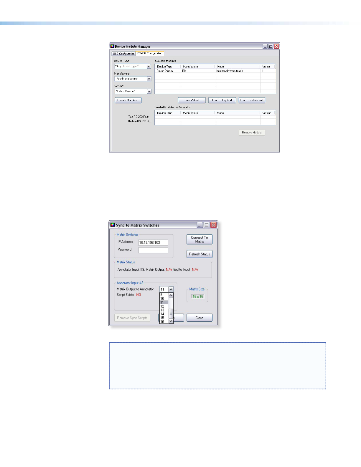
Figure 30. The Device Module Manager Window: RS-232 Tab
• Sync Scaler to Matrix Switcher — Select this to open a secondary
window. Within that window enter the IP address of the matrix switcher that is
connected to the Annotator. If required enter the password, then click Connect to
Matrix. Select the output number from the Matrix Output to Annotator
drop-down list and click Take. The Matrix Status section displays the matrix output
that is being monitored and the tied input. The Matrix Size section displays the current
Matrix size (for example a 16 x 16 I/O unit) being used.
Figure 31. Sync to Matrix Switcher Window
NOTE: The matrix switcher must be connected to via a configured input on the
Annotator. See page 26 for information.
The matrix and the Annotator must to be connected to an active
network at all times to allow the products to remain synchronized. If the
connection is lost, the script needs to be restarted by either sending the
E
SIS command (
}
1AE
) or by power cycling the Annotator.
Click Refresh Status to update the status of the matrix switcher. Refreshing the
status returns updated information about which Annotator input is tied to a particular
matrix output.
If the matrix IP address needs to be changed or which output of the matrix the
Annotator is connected to, click Remove Sync Scripts.
Annotator • SPPCP 67
Page 74

• System Settings... — Select this to open a secondary window. This allows changes
to be made to various device settings: IP and RS-232 connections, date/time, and
passwords. Select the applicable tab, change the settings as desired, and click
Submit to make the changes effective.
NOTE: • Changing the IP address may result in loss of connection to the LAN.
• Only the baud rate can be changed when selecting the RS-232 tab.
Figure 32. System Settings Window
Click Cancel or the X in the window’s top right corner to exit without changes.
• Reset — If it is necessary to reset the Annotator, select this to open a secondary drop-
down box. Two options are available: Reset to Factory Defaults and Reset to Absolute
Defaults Except IP Settings.
• Reset to Factory Defaults resets all settings on the device to their factory
defaults, including all video and audio settings, and clears all configuration files
from the device.
• Reset to Absolute Defaults Except IP Settings resets all setting on the device
to their defaults, including all captured images and the customized On Screen
Display. IP settings are not reset.
Select either option as desired.
• Update Firmware... — Selecting this opens the
Firmware Loader application (where already installed
on a connected PC). The Firmware Loader uploads new
firmware to the device, through a serial port or TCP/IP
connection.
In order for the Update Firmware function to work, the
Firmware Loader application must be installed on the
connected PC.
If already installed, skip steps 1 through 4.
Annotator • SPPCP 68
Page 75

To download and install the Firmware Loader application:
1. Go to www.extron.com.
2. Enter “Firmware Loader” in the Search eld and press Enter.
3. Locate the Firmware Loader application in the results and click Download Now!
4. Follow the on-screen prompts to complete the download.
To update the firmware:
1. From the SPPCP Tools menu, select Update Firmware. The SPPCP minimizes
and the Firmware Loader application opens.
NOTE: For full instructions about using the Firmware Loader, click Help >
Help (or <F1>) on the open Firmware Loader window
2. In the Firmware loader window, click File > New Firmware for Selected
Devices. A dialog box opens to enable a search for the device-specific firmware file
(with the file extension “.S19”) that has been downloaded to the connected PC.
Figure 33. Firmware Loader Main Window
3. In the dialog box, browse to the file location. Click on the file then click Open.
The dialog box closes, and the file name appears in the Firmware Loader window.
Figure 34. Choosing Firmware File Window
4. Click Begin. The file uploads to the Annotator and the upload progress can be seen
on the Total Progress bar.
Annotator • SPPCP 69
Page 76
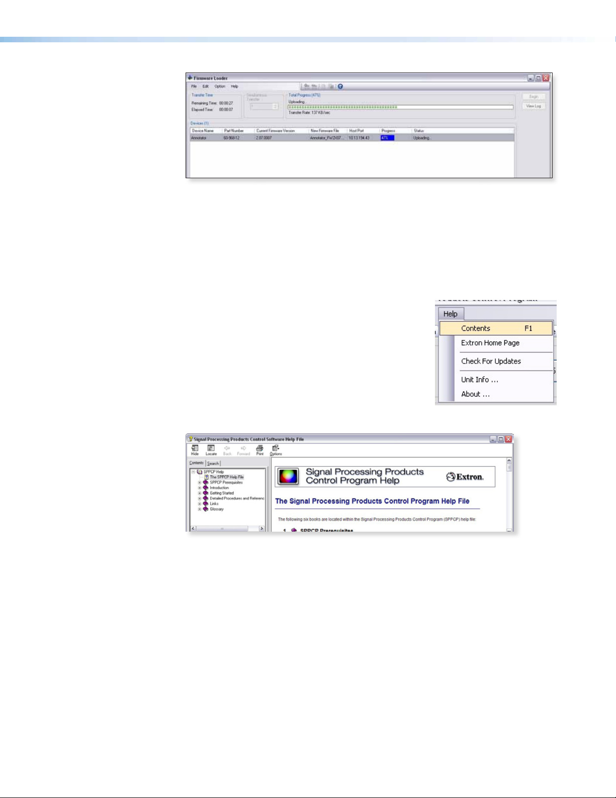
Figure 35. Firmware Loading Progress Window
5. When the le upload is complete (after file verification and the device restarting),
click on the X at top right, or on File > Exit to exit the Firmware Loader. The
SPPCP window restores itself.
6. Connection to the unit must be reestablished since the connection is lost during
firmware upload. Open the SPPCP Connect dialog box and re-enter the connection
information to re-establish communication with the Annotator.
Help menu
Click on this to open a drop-down menu displaying five
selectable options: Contents, Extron Home Page,
Check for Updates, Unit Info...,
and About....
• Contents — Select this (or press <F1>) to bring up the
Help le which gives step-by-step instructions to
configure the Annotator using the SPPCP program.
The help file opens a separate window. Select the
subject matter from the contents section at the left side of the window.
Figure 36. The Main Window of the Help File for Control Program
• Extron Home Page — This opens the Extron website (www.extron.com)
home page. From this link, device firmware and necessary applications such as
Firmware Loader and IP Link File Manager can be downloaded, and supporting
documentation for Extron products can be viewed.
• Check For Updates — Select this to update the software control program
(SPPCP). If an update is available follow any on-screen instructions to install it. A dialog
box appears if no updates are currently available. Click OK or the X in the window’s
top right corner to close it.
• Unit Info... — Selecting this opens a dialog box with information about the
connected device. The box shows the part number, the name, model description,
currently installed firmware version and build, and the device’s internal temperature.
• About... — Select this for details (version/build number, for example) of the SPPCP.
Annotator • SPPCP 70
Page 77

Control Tab
The Control tab displays the current configuration of the Annotator, with numbered
boxes representing the video inputs. Also shown on the Control tab are the PIP control
buttons, current picture adjustment values, input and user presets, as well as Video
Mute, Freeze and Auto Image buttons..
Figure 37. The Control Tab Screen
• Inputs — The current active input is shown (yellow). Select a desired input button to
change to that input.
• PIP Control — To swap a selected picture-in-picture input for the main input as
desired, click Swap. To select a different PIP input click on that PIP input button, then
click Swap. To turn the PIP feature off, click Off.
• Picture Adjustments — The Picture Adjustments section at the bottom of the
Control tab has three tables: Image, Input Settings, and Zoom/Pan. Each table’s
value field can be adjusted as desired. Refer to the SPPCP Help File for details. When
PIP is active all picture adjustments affect only the PIP image.
• Input Presets — The specific settings for size, centering, contrast, brightness, detail,
zoom, and input conguration of an input can be saved to a preset. Up to 128
input presets can be saved. A saved preset can be recalled as desired. Select a preset
number and click Save or Recall as applicable.
NOTE: Saving to an existing preset overwrites the prior saved data in favor of the
new.
• User Presets — A user preset saves specific settings for color, brightness, detail,
size, zoom and pan, and centering and up to 16 user presets per input are available.
These settings can then be recalled and applied to an applicable input. Select a preset
number and click Save or Recall as desired.
• Video Mute — Select this to mute or unmute the video image. When selected, the
button text turns red.
• Freeze — Select this to freeze an image for use as a logo or for annotation.
• Auto Image — Select this to perform an auto image on an input.
Annotator • SPPCP 71
Page 78

I/O Conguration Tab
The I/O Configuration tab allows input and output conguration, as well as EDID
emulation settings to be adjusted.
Figure 38. The I/O Configuration Tab Screen
• Input Config — Set a suitable video type for an input by clicking on the drop-down
box (see input 7 above) and selecting a listed video type.
If Auto Image on an input is desired mark the check box.
Check Film Mode if 3:2 pull down detection for NTSC and 2:2 film detection for PAL
video sources is relevant.
• Output Config — To configure an output resolution, refresh rate, output type, or
sync polarity, select the desired values from the respective drop-down list.
• EDID Emulation — To set resolution and refresh rates for EDID emulation on the
VGA/DVI inputs, select the values from the drop-down list. Alternatively select Match
Output to automatically set the EDID to match the output resolution and refresh
rate.
Annotator • SPPCP 72
Page 79

Advanced Settings Tab
The Advanced Settings tab allows advanced functions to be configured. These
include test pattern selection, and advanced features, used primarily during initial setup.
Figure 39. The Advanced Settings Tab Screen
• Test Pattern — Select any of the 14 test patterns to aid setting up an output display
device. A small thumbnail of the pattern is shown on the tab (see above). Select Off
where a test pattern is not needed.
• Aspect Ratio — Aspect ratio mode adjusts the aspect ratio of the output. The
available options are Fill, which fills the output raster, and Follow, which follows
the aspect ratio of the selected input signal. Black bars remain on either the top and
bottom or the sides. Click the radio button for the desired option (Fill or Follow).
• Advanced Features — Within this section RGB delay can be adjusted (from 0 to 5.0
seconds) in 0.1 second intervals with each click of the scroll arrows. In addition, auto
memory can be turned on or off, and switch effect can be activated. If using mini
twisted pair devices, pre-peaking can be turned on to compensate for long cable runs.
• On Screen Display — Within this section selections can be made to how annotation
display and cursor display is handled by choosing from each drop-down list. In
addition by selecting or deselecting a check box, drop shadow on annotations can be
turned on or off.
• Capture Mode — These two selectable radio buttons allow a choice of locations for
saving Quick Capture captured images to either internal or external memory.
• Menu — The menu section allows a choice of display modes (all outputs, program
only, preview only, or none) and the display duration, either from 1 to 64 seconds
(adjustable in 1 second intervals) or always on. Select as desired.
• Clock — In this section the clock display mode can be set or disabled, and the
on-screen horizontal and vertical position can be adjusted.
Annotator • SPPCP 73
Page 80
Scan Converter Tab
NOTE: The Scan Converter tab appears only if the optional scan converter
The Scan Converter tab allows viewing and changing of the configuration settings of
the optional scan converter output board.
output board is installed in the Annotator.
Figure 40. The Scan Converter Tab Screen
• Picture Adjustments — The Picture Adjustments and Image Filter sections of the
Scan Converter tab allows adjustments to be made to the image settings of the
scan converted output. Adjustable image settings are: Horizontal Center,
Vertical Center, Horizontal Size, and Vertical Size. Change the
value field (from 0 to 4095) as required. In addition the Image Filter settings (flicker,
horizontal detail, and encoder sharpness) can be set as desired from each drop-down
list.
• Output Config — In this section the output standard (PAL or NTSC) and the format
of the scan converted output (S-video/composite, YUVi, or RGsB) can be set. Select
the applicable standard and format as desired.
Annotator • SPPCP 74
Page 81

Aux Scaler Tab
NOTE: The Aux Scaler tab appears only if the optional aux scaler output
The Aux Scaler tab allows you to view and change the configuration settings of the
optional Aux scaler output board.
board is installed in the Annotator.
Figure 41. The Aux Scaler Tab Screen
• Output Config — In this section the resolution, refresh rate, output type, and sync
polarity can be set. The refresh rate selection is dependent on the resolution rate
chosen. Click on the respective drop-down menu and select the desired option.
• Aspect Ratio — From this section, adjustments can be made to the aspect ratio,
where the aspect of the main output does not match that of the scaler board output.
The available options include Fill (fills the output raster) and Follow (follows the
aspect ratio of the main output). Black bars remain on either the top and bottom or
the sides.
• Detail — Use this section to adjust the sharpness of the image output of the scaler
output board. Click the Up and Down arrows to incrementally increase or decrease the
value, or enter a value (0 to127) in the value field.
• Test Pattern — This option allows for the selection of a test pattern to output
to the display device connected to the scaler board output. These test patterns
are unique to the scaler board output and do not affect the other outputs of the
Annotator.Available test patterns include: Color bars,4 X 4 Crosshatch,
Grayscale, Ramp, Alternating Pixels, and Crop. Select a test pattern
from the drop-down list. A preview of the selected test pattern appears below the list.
Annotator • SPPCP 75
Page 82

Image Capture Tab
The Image Capture tab allows capturing, saving, recalling, and deletion of displayed
images.
Figure 42. The Image Capture Tab Screen
• Image Capture — Use this section to capture a displayed image to the Annotator
internal memory. Enter a suitable name (maximum 12 characters) and click Capture.
• Image Recall — Use this section to recall a captured image. Select the desired image
and click Preview to see a thumbnail image on the connected PC, or Recall to
show the image on a connected display device. In addition, a displayed image can be
hidden and a captured image can be deleted within this section.
Annotator • SPPCP 76
Page 83
Font Tab
The Font tab allows generation and selection of font type used by the Annotator.
Figure 43. The Font Tab Screen
• Font Generation — Use this to generate a font type to use by selecting from the
font Type drop-down list and font style (regular or bold). Select the country whose
font characters are to be used (United States, France, or Germany) and click Load.
Enter a le name for the saved font le in the Save As dialog box and click Save.
• Font Selection — Within this section select a font to use from the list and click
Apply. If so desired check the Set to Default Font box. To delete a font select it and
click Delete.
For full details on the tabs and using the software, refer to the help file within the SPPCP.
Status Bar
The status bar appears at the bottom of the SPPCP screen. It displays information about
the application’s current status as well as that of the device.
It shows unit connected, connection type (IP address or comm port), current user
permission level (for example, administrator), and any error information. If connected via
Telnet, then the IP address or unit name of the device are displayed, and if connected via
serial port, the baud rate and port number are displayed. Error information appears for
5 seconds in the status bar and then is replaced by connection and device information.
Annotator • SPPCP 77
Page 84
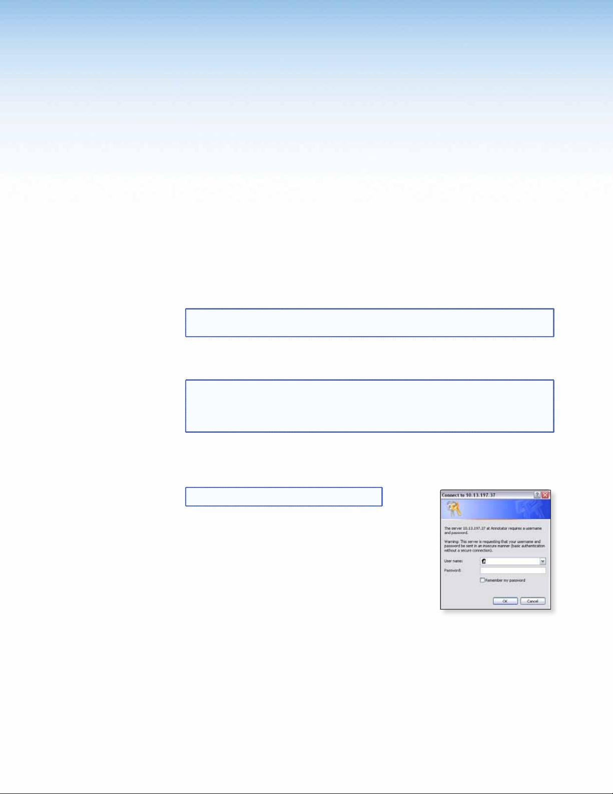
HTML Operation
This section describes these default web pages, which are always available and cannot be
erased or overwritten. Topics that are covered include:
• Accessing the Default Web Pages
• Navigating the Default Web Pages
Accessing the Default Web Pages
Access the Annotator through the on-board web server pages as follows:
1. Double click the web browser icon on the PC desktop to launch the web browser.
2. Click in the browser’s Address field.
3. Enter the unit’s IP address in the browser’s Address field.
NOTE: If the local system administrators have not changed the value, the factory-
specified default, 192.168.254.254, is the correct value for this field.
4. To have the browser to display a page other than the default page (such as a custom
page that you have created and uploaded), enter a slash (/) and the file name to open.
NOTE: The browser Address field should display the address in the following
format: xxx.xxx.xxx.xxx/{optional_file_name.html}
The following characters are invalid in file names: {space} ~ @ = ‘ [ ] {
} < > ’ “ ; : | \ and ?.
5. Press the keyboard <Enter key>. The device checks to see if it is password protected.
If password protected, the Annotator downloads the Connect to (IP
address) page. If it is not password protected, proceed to step 7.
NOTE: A user name entry is not required.
6. Click in the Password field and type in the appropriate
administrator or user password.
7. Click OK.
The device checks several possibilities, in the following
order, and then responds accordingly:
• Does the address include a specific file name, such
as 10.13.156.10/file_name.html? If so, the
Annotator downloads that HTML page.
• Is there a le in the device memory that is named “index.html”?
If so, the device downloads “index.html” as the default start-up page.
• If neither of the above conditions is true, the device downloads the factory-
installed default start-up page, “nortxe_index.html”, also known as the System
Status page.
Annotator • HTML Operation 78
Page 85

Navigating the Default Web Pages
The Annotator default web pages include five main tabs or pages (Status,
Configuration, File Management, Control, and Images). These pages
can be accessed at any time by clicking on the relevant tab. Some of the main pages have
a series of sub-pages, accessible by clicking on the links in the sidebar menu allowing easy
navigation of several administrative options including system settings, password control,
file management, and device settings.
Status Tab
The Status tab displays the System Status page for the Annotator.
System Status page
The System Status page displays system information (for example, unit name, model,
firmware version), IP settings, and serial port settings. It provides immediate system
information, power status and serial port settings for the Annotator unit. The page
updates itself periodically to reflect the latest status of the Annotator components. If a
variable changes, the display shows the change in status the next time it updates.
Figure 44. System Status Page
Annotator • HTML Operation 79
Page 86

Conguration Tab
The Configuration tab includes pages that allow System settings (such as IP address,
date/time, and so forth), scaler settings, and passwords (admin and user), to be configured
as desired. Additionally by selecting the Firmware Upgrade link the current rmware can
be upgraded. If an optional board such as the Aux Scaler board has been installed a
configuration page for the board will also be available.
System Settings page
The Annotator displays the System Settings page when you click on the
Configuration tab. The screen consists of fields in which you can view and edit IP
administration and system date and time settings. See the “Ethernet Connection” section
at the end of this guide for basic information about IP addresses and subnetting.
Figure 45. System Settings Page
On password-protected connections, there are two levels of protection: administrator and
user. Administrators have full access to all unit capabilities and editing functions. Users
can change inputs, create and recall presets, change images, and view all settings with the
exception of passwords.
• Ethernet connection to the unit, either entering SIS commands
(see “SIS Communication and Control” section) or using the Extron Signal Processing
Products Control Program (see the “Signal Processing Products Control Program”
section) is password protected.
• Connection via the RS-232/RS-422 port is not password protected.
IP settings fields
The IP settings fields provide a location for viewing and editing settings unique to the
Ethernet interface. After editing any of the settings on this page, click Submit.
Explanations for some of these elds follow.
Unit Name
This name field can be changed to any valid name, up to 12 alphanumeric characters.
NOTE: The following characters are invalid in the name: {space} ~ @ = ‘ [ ] { } <
> ’ “ ; : | \ and ?.
Annotator • HTML Operation 80
Page 87

DHCP radio buttons
The DHCP On radio button directs the device to ignore any entered IP addresses and to
obtain its IP address from a Dynamic Host Conguration Protocol (DHCP) server (if the
network is DHCP capable).
The DHCP Off radio button turns DHCP off. Contact the local system administrator to
determine this control setting.
IP Address
The IP Address field contains the IP address of the Annotator. This value is encoded in
the unit’s flash memory.
Valid IP addresses consist of four 1-, 2-, or 3-digit numeric subelds separated by dots
(periods). Each eld can be numbered from 000 through 255. Leading zeros, up to 3 digits
total per eld, are optional. Values of 256 and above are invalid.
The factory-installed default address is 192.168.254.254, but if this conflicts with other
equipment at your installation, you can change the IP address to any valid value.
NOTE: Editing the Extron IP address while connected via the Ethernet port can
immediately disconnect the user from the scaler. Extron recommends
editing this eld using the RS-232 link and protecting the Ethernet access
to this screen by assigning an administrator password to qualified and
knowledgeable personnel only.
Edit this eld as follows:
1. Click in the device IP address field. The graphic cursor becomes a text cursor.
2. Edit the address as desired.
3. Press the <Tab> key on the keyboard or click in another field to exit the IP Address
field.
4. Click on the Submit button to make the address change take effect.
Gateway IP Address
The Gateway IP Address field identifies the address of the gateway to the mail
server to be used if the Annotator and the mail server are not on the same subnet.
The gateway IP address has the same validity rules as the system IP address.
Subnet Mask field
The Subnet Mask field is used to determine whether the Annotator is on the same
subnet as the controlling PC or the mail server when you are subnetting.
MAC Address field
The Media Access Control (MAC) Address is hard coded in the device and cannot be
changed.
Firmware field
This field shows the firmware version number. This field changes only when the firmware
is updated.
Model field
This field shows the model (Annotator) and cannot be changed.
Part Number field
This field shows the Annotator part number (60-968-xx) and cannot be changed.
Annotator • HTML Operation 81
Page 88
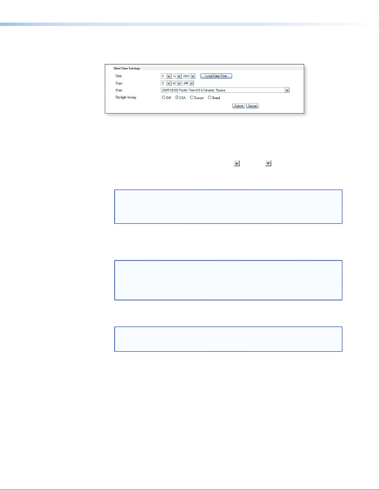
Date/Time Settings fields
The Date/Time Settings fields provide a location for viewing and setting the time functions.
Figure 46. Date/Time Settings fields
Change the date and time settings as follows:
1. Click the desired variable’s drop-down box. The adjustable variables are month, day,
year, hours, minutes, AM/PM, and (time) zone. A drop-down scroll box appears.
2. Click and drag the slider or click the scroll up or down buttons until the desired
variable is visible.
3. Click on the desired variable.
NOTE: • If setting the time, set the local time.
• The Zone field identifies the standard time zone that has been selected
and displays the amount of time, in hours and minutes, that the local
time varies from the GMT international time reference.
4. Repeat steps 1 through 3 for other variables that need to be changed.
5. Select the appropriate Daylight Saving radio button. To turn off daylight savings
time, select Off.
NOTE: When daylight saving time is enabled, the unit updates its internal clock
between Standard Time and Daylight Saving Time in the spring and fall on
the date that the time change occurs in the United States of America and
6. Click Submit at the bottom of the Date/Time Settings section to implement your
selections.
NOTE: Click Cancel at any point before submitting to exit any field changes.
parts of Europe and Brazil. When daylight saving time is turned off, the
unit does not adjust its time reference.
The unit is not updated with those changes. The screen refreshes and
shows the current device settings.
Annotator • HTML Operation 82
Page 89

Scaler Settings page
Access the Scaler Settings page by clicking the Scaler Settings link on the sidebar
menu on the Configuration page.
Figure 47. Scaler Settings Page
The Scaler Settings page displays Input Configuration settings (input signal format,
auto image and film mode status), Output Configuration settings (resolution and refresh
rates, output sync format, and polarity), Advanced Conguration settings (RGB delay, test
pattern selection, auto memory status, aspect ratio mode, switch effect, MTP
pre-peaking settings, and EDID resolution and refresh rates), and On Screen Display
settings. Any settings can be changed and the unit updated to the new settings. The page
updates itself periodically to reflect the latest status of the Annotator components. If a
variable changes, the display shows the change in status the next time it updates.
Input configuration
For each of the seven inputs, the input format can be changed by clicking on the dropdown list arrow and selecting the appropriate signal type:
NOTE: Selecting Auto Detect allows the device to automatically set the input to
the appropriate signal format.
Input 1: RGB, YUVp/HDTV, Auto Detect
Input 2: RGB, YUVp/HDTV, Auto Detect
Input 3: RGB, YUVp/HDTV, RGBcvS, YUVi, S-video, Composite, Auto Detect
Input 4: YUVi, S-video, Composite, Auto Detect
Input 5: S-video, composite, Auto Detect
Input 6: DVI
Input 7: SDI, HD-SDI, Auto Detect
For each input Auto Image can be set on or off.
For each of the inputs film mode can be enabled or disabled.
NOTE: Film mode processing helps maximize image detail and sharpness for NTSC,
PAL, and HDTV 1080i sources that originated from lm.
Annotator • HTML Operation 83
Page 90

Output configuration
Depending on the optional output card installed, the output connector and display device
being used, the resolution and refresh rates can be set to one of various output rates from
640x480/50 Hz to 1920x1200, including HDTV 1080p/60 Hz. For a full table of output
rates see page 20.
The output sync format can be chosen from RGBHV, RGsB, YUV bi-or tri-level sync.
Output polarity can be selected from H-/V- (default), H+/V-, H+/V+, or H-/V+.
Advanced configuration
Within this section, RGB delay can be set from a range of 0.0 seconds up to 5.0 seconds
in 0.1 second steps. Use the drop-down box to select the desired setting. When switching
inputs, the new input is displayed after the current RGB delay time, for example, 2.0
seconds.
If desired, an internal test pattern can be selected from the drop-down list of 14 patterns
in order to aid the setting up a display device.
Switch effect can be toggled between Cut and Fade. The selected effect is seen on the
connected display when inputs are switched.
Auto memories can be toggled on or off as desired.
Aspect ratio can be set to either Fill or Follow.
When using the MTP (mini twisted pair) output, the pre-peaking setting can be turned
on or off to compensate for the poor image quality of video signals transmitted over
long distance twisted pair cable runs to a remote display. A compatible Extron MTP Series
Twisted Pair Receiver is required for this output type.
Using EDID emulation, the Annotator provides a means for specifying the rate of the
incoming DVI or VGA signal, and allows proper communication with the video source.
EDID settings can be selected from the drop-down resolution and refresh rate lists.
Figure 48. RGB Delay, Test Pattern, and EDID Selections
Annotator • HTML Operation 84
Page 91

On Screen Display
Within this section, some aspects of the on screen display can be set. The annotation,
cursor display can be set to be seen on all outputs, or where used, either group 1 or
group 2 only, or on no outputs at all. The annotation menu display can also be set to be
seen on all outputs, or where used, either group 1 or group 2 only, or on no outputs at
all. In addition where the menu is to be displayed, the length of time the menu is visible
can be set, the range being from 1.0 seconds up to 64.0 seconds (in 1 second steps), or
can be set to always on.
Aux Scaler page
The Aux Scaler page, available only if the Aux Scaler board is installed, can be
accessed by clicking the Aux Scaler link on the sidebar menu on Configuration page.
Figure 49. Aux Scaler Page
Output configuration
Depending on display device being used, the resolution and refresh rates can be set to one
of various output rates from 640x480/50 Hz to 1920x1200, including HDTV 1080p/60 Hz.
For a full table of output rates see page 19.
The output sync format can be chosen from RGBHV, RGsB, YUV bi-or tri-level sync.
Output polarity can be selected from H-/V- (default), H+/V-, H+/V+, or H-/V+.
Aspect ratio
Aspect ratio can be set to either Fill or Follow (default).
Detail
The detail setting can be adjusted for 0 to 127. 64 is the default.
Test pattern
A test pattern, useful when setting up a display, can be
selected for the drop-down list.
Annotator • HTML Operation 85
Page 92
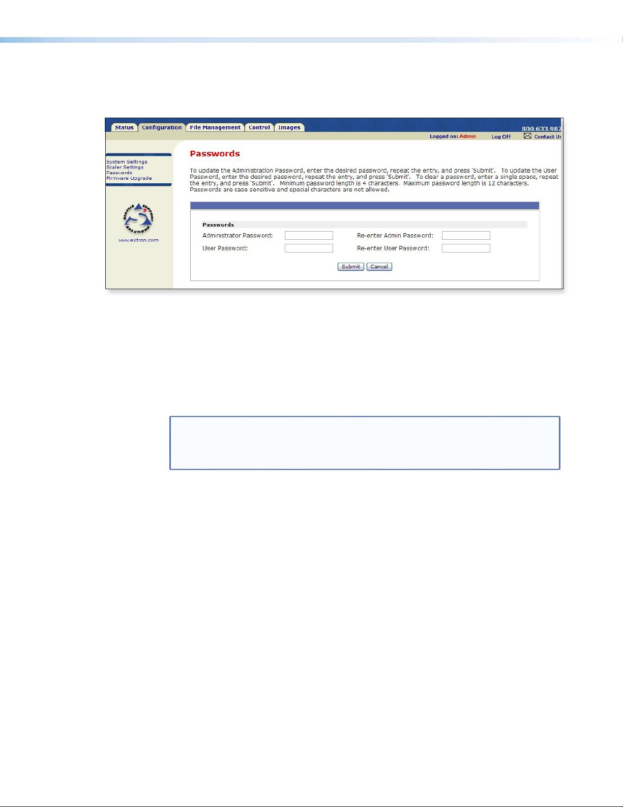
Passwords page
Access the Passwords page by clicking the Passwords link on the sidebar menu on
Configuration page.
Figure 50. Passwords Page
The fields on the Passwords page are for entering and verifying administrator and
user passwords. Passwords are case sensitive and are limited to 12 upper- and lowercase
alphanumeric characters. Each password must be entered twice – once in the Password
field and then again in the Re-enter Password field to the right. Characters in these
elds are masked by four bullets (••••). If you do not want to password-protect an access
level, leave the Password and the Re-Enter Password fields blank. After entering
the desired password in both fields, click Submit at the bottom of the page.
NOTE: • An administrator password must be created before a user password can be
created.
• Some items may not be available or may be viewable only, when logged in
as a user.
To clear an existing password so that no password is required, delete the bullets in the
Password and Re-enter Password fields and enter a space in each field, then click
Submit at the bottom of the page.
Annotator • HTML Operation 86
Page 93

Firmware Upgrade page
Access the Firmware Upgrade page by clicking the Passwords link on the sidebar
menu on Configuration page.
The Firmware Upgrade page provides a way to replace the firmware that is coded on
the Annotator control board without taking the processor out of service.
Figure 51. Firmware Upgrade Page
NOTE: The Firmware Upgrade page is only for replacing the rmware that controls all
processor operation. To insert your own HTML pages, see “File Management”
later.
Ensure that your PC is connected to the Annotator via the scaler’s Ethernet port. Update
the scaler firmware as follows:
1. Visit the Extron website, www.extron.com, and download the latest firmware file to
your computer.
a. On the Extron web page, select the Downloads tab.
b. On the Download Center page, click the Firmware link on the left sidebar
2. Access the Annotator internal web pages.
3. Select the Configuration tab.
4. On the Configuration page, click Firmware Upgrade on the left sidebar menu.
5. Click Browse. A Choose File window opens.
6. Navigate to the folder (created in 1g) where the firmware upgrade file is saved and
menu.
c. Click on the Annotator name.
d. On the next screen, fill in the required information, then click the Download
product name_firmware version.exe button.
e. On the File Download - Security Warning window, click Save.
f. On the Save As window, browse to the folder where you want to save the
firmware file, and click Save. The firmware installation (.exe) file is placed on
your hard drive.
g. Run the .exe le. This opens the Firmware Update program, creating a product
named folder within which is placed the firmware file (x.S19).
select the file.
Annotator • HTML Operation 87
Page 94

Figure 52. Choose File to Upload Widow with a Firmware File Selected
NOTES: • Valid rmware les must have the le extension “.S19”. Any other le
extension is not a firmware upgrade.
• The original factory-installed firmware is permanently available on the
scaler. If the attempted firmware upload fails for any reason, the scaler
automatically reverts to the factory-installed firmware.
7. Click Open.
8. Click Upload. While the rmware is uploading, the Upload button changes to
“Uploading...” . When the uploading process is complete, the button changes back to
Upload. The uploading may take a few minutes.
Annotator • HTML Operation 88
Page 95

File Management Tab
This tab shows the File Management page, and allows the user to upload or delete
user les (such as HTML pages, or bitmaps) from the Annotator.
To add or update files:
1. Select the File Management tab. The File Management screen is displayed.
Figure 53. File Management Page
NOTE: The files listed above are shown for example only.
2. Click the Browse button to locate the file(s) you want to upload.
NOTE: If you want one of the pages that you create and upload to be the default
start-up page, name that file “index.html”
3. Click the Upload File button to upload the file.
4. The file is added to the list of files under the Files column. After ten files have been
loaded, additional file management pages appears in the page navigation area.
To add a directory:
1. Enter the directory name in the Dir field.
2. Click the Add Dir button.
3. Click the Browse button, and locate your chosen directory.
4. Upload a le to the new directory.
To delete unwanted files:
1. Select the File Management tab. The File Management screen is displayed.
2. Find the file you wish to delete under the Files list.
3. Click the Delete button of the file to be deleted. If you wish to delete additional
files, wait for the screen to refresh before clicking the Delete button of the next file.
To delete all files, click Delete All. File count reverts to zero and all pages are
deleted.
Display files by file extension — The Filter by File Extension menu lists the extensions of
the uploaded files. The user can choose to display only files with the selected extension.
Click Select All to display all uploaded files.
Annotator • HTML Operation 89
Page 96
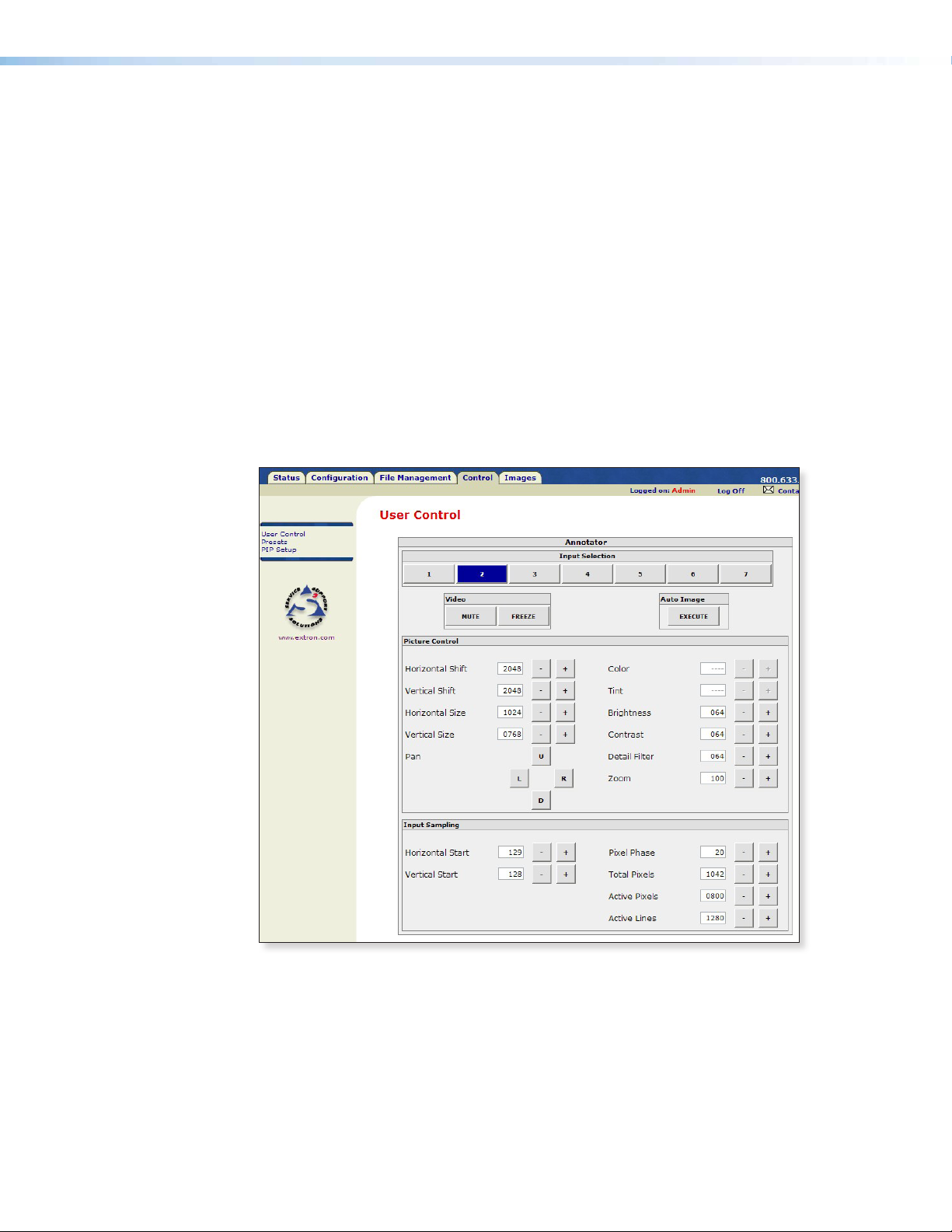
Control Tab
The three pages on the Control tab are User Control, Presets, and PIP Setup, and they
allow limited device configuration.
From the User Control page, the selection and viewing of inputs, mute and freeze
selection, and execution of Auto Image is possible. Picture control and input sampling is
also available on the User Control page.
From the Presets page, up to 16 memory presets and up to 30 input presets can be saved
and recalled.
Using the PIP (picture-in-picture) page, an input can be selected and swapped to become
either the main image or the secondary (PIP) image. In addition, the PIP can be turned off
and auto image can be performed an either input. Within PIP Setup limited picture control
is possible. The Control pages initially open on the User Control page.
User Control page
This page emulates some of the front panel features and displays the current picture
control settings and input sampling data. In addition, image muting or unmuting, image
freezing or unfreezing and Auto Image can be selected.
Figure 54. User Control Page
To select an input to be displayed, click on an input number. The selected input is
displayed.
To mute or unmute, freeze or unfreeze the input image, click on the appropriate
button. Muting the image blanks the display screen. Unmuting the image allows the
image to be displayed.
Freezing the image keeps the same image displayed, even when the input is switched.
Unfreezing the image allows images from switched inputs to be viewed.
Annotator • HTML Operation 90
Page 97

Presets page
From this page up to 16 memory or 128 input presets can be saved and recalled.
Figure 55. Presets Page
To save the current configuration to a memory or input preset, click on the applicable
drop-down box, scroll to the desired preset number and click Save.
To recall a memory or input preset as the current configuration, click on the applicable
drop-down box, scroll to the desired preset number and click Recall.
The current configuration is then replaced by the recalled configuration.
PIP Page
With this page, picture-in-picture setup is possible by selecting the main image and the
secondary PIP image inputs.
Figure 56. PIP Page
To toggle between two inputs click Swap.
To turn off the PIP format click Off.
Auto image mode is applied to any selected input when Auto Image is clicked on.
Annotator • HTML Operation 91
Page 98
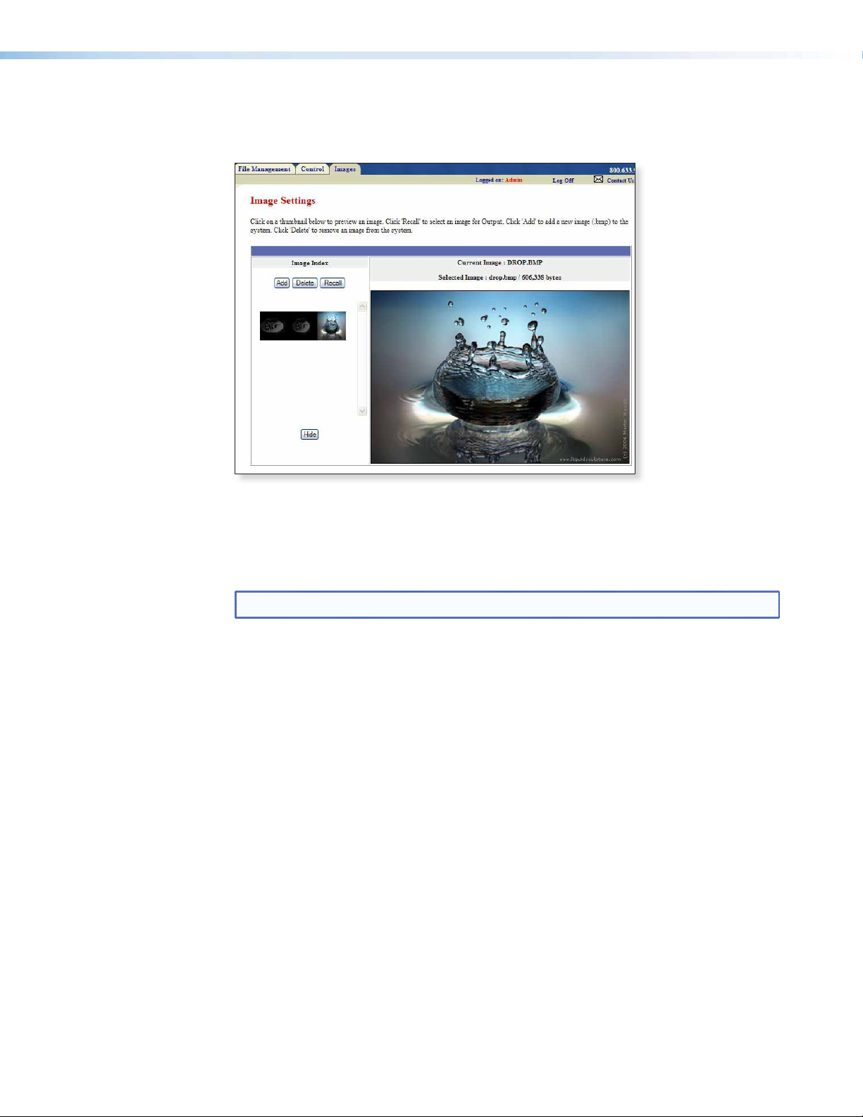
Images page
This page allows images (.bmp format) to be added to or deleted from the Annotator,
previewed, and recalled to be shown on a connected display device.
Figure 57. Images Page
To add an image, click Add, browse to the image location on the connected PC, and click
Upload Image. The image is uploaded to the Annotator and a thumbnail of the image is
viewable on the Images page (see the figure above).
NOTE: The image is not yet displayed.
To preview an image without displaying it, click on the thumbnail.
To display an image click on a thumbnail image and then click Recall. The image is
displayed. If no image appears on the display device, check the input selected and image
format is correct.
To delete an image click on a thumbnail and then click Delete. The image is deleted
from the Annotator files.
Annotator • HTML Operation 92
Page 99

Reference
Material
This section provides information about:
• Specifications
• Part Numbers and Accessories
Specications
Video input
Number/signal type ........................ 2 RGBHV, RGBS, RGsB, component video (Y, R-Y, B-Y; progressive or HD)
1 RGBHV, RGBS, RGsB, component video (Y, R-Y, B-Y; interlaced, progressive, HD),
S-video, composite video
1 component video (Y, R-Y, B-Y; interlaced), S-video, composite video
1 S-video, composite video
1 single link DVI-D
1 optional SDI, HD-SDI
Connectors .................................... 2 female 15-pin HD: RGBHV, RGBS, RGsB, component video
5 female BNC: RGBHV, RGBS, RGsB, component video, S-video, composite video
3 female BNC: component video, S-video, composite video
2 female BNC: S-video, composite video
1 female DVI-I: DVI-D
1 female BNC: optional SDI, HD-SDI
Nominal level ................................. 1 Vp-p for Y of component video and S-video, and for composite video
0.8 Vp-p for SDI
0.7 Vp-p for RGB and for R-Y and B-Y of component video
0.3 Vp-p for C of S-video
Minimum/maximum levels .............. Analog: 0.0 V to 2.0 Vp-p with no offset
Impedance ..................................... 75 ohms
Horizontal frequency ...................... Autoscan 15 kHz to 100 kHz
Vertical frequency ........................... Autoscan 24 Hz to 120 Hz
Resolution range ............................ 640x480 to 1920x1200*, 480i, 480p, 576i, 576p, 720p, 1080i, and 1080p, digitized
pixel for pixel; higher resolutions are undersampled.
*Reduced blanking
Return loss ..................................... <-30 dB @ 5 MHz
DC offset (max. allowable) ............. 0.5 V
Video processing
Digital sampling ............................. 30 bit, 10 bits per color; 13.5 MHz standard (video), 165 MHz standard (RGB, YUVp, DVI)
Colors ............................................ 1 billion, 1024 per color channel
Encoder (for scan converted output) 10 bit digital
Horizontal ltering (for scan converted output)
3 levels
Vertical ltering (for scan converted output)
3 levels
Encoder ltering (for scan converted output)
3 levels
Annotator • Reference Material 93
Page 100

Video output
Number/signal type ........................ 2 buffered scaled RGBHV, RGBS, RGsB, or HD component video (Y, R-Y, B-Y)
Connectors .................................... 6 female BNC: RGB or component video
Nominal level ................................. 1 Vp-p for Y of component video and S-video, and for G of RGsB
Minimum/maximum levels .............. 0.0 V to 1.0 Vp-p
Impedance ..................................... 75 ohms
Scaled resolution ............................ 640x480
Formats .......................................... For DVI output: RGB and YCbCr digital video
Sync
Input type ...................................... RGBHV, RGBS, RGsB, RGBcvS, and component video (tri-level or bi-level)
Output type ................................... RGBHV, RGBS, RGsB, and component video (tri-level or bi-level)
Standards ....................................... NTSC 3.58, NTSC 4.43, PAL, SECAM
Input level ...................................... 2.75 V to 5.0 Vp-p for RGBHV or RGBS
Output level ................................... 5.0 Vp-p for RGBHV or RGBS
Input impedance ............................ Horizontal: 75 ohms
Output impedance ......................... 75 ohms
Polarity ........................................... Positive or negative (selectable)
Control/remote— signal processor
Serial control port ........................... 2 RS-232/RS-422, female 9-pin D connectors (rear panel)
Baud rate and protocol ................... 9600 (default), 19200, 38400, 115200 baud, adjustable; 8 data bits, 1 stop bit, no parity
Serial control pin configurations
9-pin D connector .................... RS-232: 2 = Tx, 3 = Rx, 5 = GND
2.5 mm mini stereo jack ........... Tip = Tx, ring = Rx, sleeve = GND
Ethernet control port ...................... 1 RJ-45 female connector
Ethernet data rate .......................... 10/100Base-T, half/full duplex with autodetect
Ethernet protocol ........................... ARP, ICMP (ping), IP, TCP, UDP, DHCP, HTTP, SMTP, Telnet
Ethernet default settings ................ Link speed and duplex level = autodetected
1 MTP
1 optional single link DVI-I (for unique scaled output); DVI-D; HD-SDI; or interlaced RGsB,
component video, S-video, composite video
1 female 15-pin HD: RGB or component video
1 female RJ-45: output to an MTP device
1 slot for an optional output card with one of the following options:
· 1 female DVI-I (analog and digital, unique scaled output)
· 1 female DVI-I (digital output)
· 1 female BNC (HD-SDI output)
· 3 female BNC (interlaced RGsB, component, S-video, composite video output)
0.8 Vp-p for SDI
0.7 Vp-p for RGB and for R-Y and B-Y of component video
0.3 Vp-p for C of S-video
6,8,9
, 800x600
1280x768
1365x1024
1920x1200
HDTV: 480p
2048x1080
SDTV: NTSC, PAL (with optional scan converter output card)
1
= 23.98 Hz, 2 = 24 Hz, 3 = 25 Hz, 4 = 29.97 Hz, 5 = 30 Hz, 6 = 50 Hz, 7 = 59.94 Hz, 8 =
6,8,9
, 1280x800
6,8,9
6,8
7,8
, 576p6, 720p
1,2,3,4,5,6,7,8
6,8,9
, 1366x768
, 852x480
6,8,9
, 1280x1024
6,8,9
, 1400x1050
3,4,5,6,7,8
6,8,9
, 1024x768
, 1080i
6,8,9
, 1360x765
6,8
, 1440x900
6,7,8
, 1080p
6,8,9
, 1024x852
6,8,9
6,8,9
1,2,3,4,5,6,7,8
6,8,9
, 1024x1024
, 1360x768
, 1600x1200
, 1080p CVT8,
6,8,9
, 1365x768
6,8
, 1680x1050
6,8,9
,
6,8,9
,
6,8
60 Hz, 9 = 75 Hz
Optional SDI/HD-SDI input: SMPTE 259M-C, SMPTE 292M
0.6 Vp-p for component video tri-level sync
0.3 Vp-p for component video bi-level sync or RGsB
0.6 Vp-p for component video tri-level sync
0.3 Vp-p for component video bi-level sync or RGsB
Vertical: 510 ohms
1 RS-232, 2.5 mm mini stereo jack (front panel)
RS-422: 2 = Tx-, 3 = Rx-, 5 = GND, 7 = Rx+, 8 = Tx+
IP address = 192.168.254.254
Subnet mask = 255.255.0.0
Gateway = 0.0.0.0
DHCP = off
,
Annotator • Reference Material 94
 Loading...