

Page 1
AKM UK Series Installation Guide
This guide provides installation instructions for the following Extron AKM UK
Series faceplates, designed for use with the Ackermann CRX 4090 or CRX 4120
floor box:
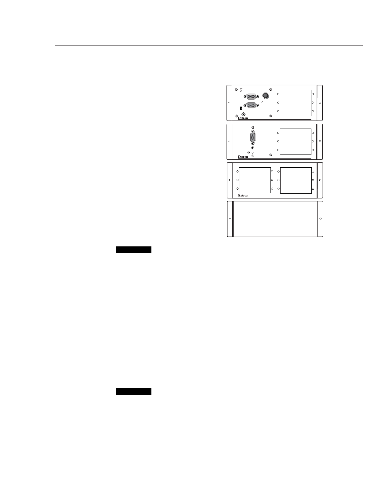
• RGB 468xi AKM UK, which
consists of an RGB 460xi Series
interface and space for three
single-size AAPs.
Part number: 60-626-01.
• Extender AKM UK AAP, which
consists of an Extender Series
VGA line driver with audio and
space for three single-size AAPs.
Part number: 60-627-01.
• AAP 106 AKM UK, which
consists of space for six single-size
AAPs with no electronics.
Part number: 60-628-01.
• AKM UK Blank, which has no
electronics or AAP openings and
is used to cover any openings left
after installing other AKM UK
Series faceplates in the floor box.
Part number: 60-629-01.
CAUTION
To ensure correct equipment placement and operation, this installation
procedure should be performed by authorized personnel only.
MONITOR
MONITOR
H. SHIFT
MONITOR
PC INPUT
PC AUDIO
PC INPUT
AUDIO
MIN/MAX
RGB 468xi AKM UK
EXTENDER AKM UK AAP
AAP 106 AKM UK
NO
Preparing the Installation Site
Take the following steps to prepare the installation site:
1. Determine the electronics, AAPs, and cabling required for this installation.
The Ackermann CRX 4090/CRX 4120 floor box can accommodate four AKM
UK faceplates.
2. Turn off all equipment. Make sure the computer, interface, and output devices
(e.g., projector, monitor, etc.) are all turned off and disconnected from the
power source.
3. Select an installation site that allows cable runs without interference. Allow
enough depth for both the floor box and the cables.
4. Install the floor box in accordance with the documentation that accompanied
the floor box.
5. Route all cables required for the installation through the floor box punch-out
holes.
CAUTION
Exposed cable shields (braids or foil) are potential sources of short circuits.
To prevent short circuits, shields should be trimmed back or insulated with
heat shrink. Both braided and foil shields should be connected to an
equipment ground at the other end of the cable.
68-904-01 Rev. A
Printed in the USA
11 03
1AKM UK Series • Installation Guide
Page 2
AKM UK Series Installation Guide, cont’d
Assembling and Pretesting the Faceplates
The faceplates and optional AAPs must be installed, cabled, and pretested before
the faceplates are mounted into the floor box.
1. Unpack the AKM UK faceplates and AAPs.
• Each faceplate has two screws: a small (#4-40 x 5/16" Phillips pan head)
machine screw and a larger (#6-32 x 1/2" Phillips pan head) self-tapping
screw. Save these screws for the “Mounting Faceplates in the Floor Box”
procedure.
• Each AAP has four #4-40 nuts and captive washers used to secure the
AAP to a faceplate. These nuts will be used in step 2 of this procedure.
2. Attach AAPs to the faceplates.
a. Insert the mounted screws on the back of the AAP through holes on the
faceplate.
b. Secure the AAP to the faceplate using the #4-40 nuts and captive washers
provided with the AAP.
c. Repeat this step until all AAPs have been installed.
D
N
E
T
X
E
Adapter Plate
(Up to 3 Plates)
#4-40 Nut w/
Captive Washer
P
A
A
K
U
M
K
A
R
E
Flange with
Large Hole
A
U
D
IO
P
C
IN
P
U
T
Connected Cables
Flange with
Small Hole
3. Set the gain and any switches on the the interface and other devices built into
or attached to the faceplates. Refer to the RGB 400xi Series User’s Manual (part
number 68-542-01), the Extender Series User’s Manual (part number 68-552-01),
or the appropriate manual for the devices being installed.
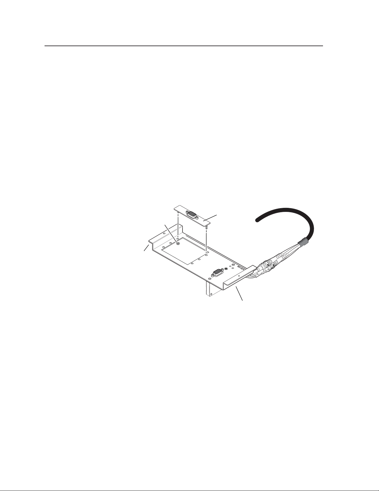
4. Connect cables to each faceplate.
a. Orient each faceplate for proper insertion into the floor box. The faceplate
flange with the large hole must be oriented toward the side of the floor
box with the smaller (self-tapping) screw holes. (Refer also to the
installation figure on the next page.)
b. Connect video, audio, and power cables to each device as explained in
the documentation that accompanied the device.
5. Connect all output device, interface, and computer power cords and then turn
on all devices.
All devices should have power, and the audio and video should be working
properly. If not, check all cabling and switch settings, and make adjustments
as necessary.
AKM UK Series • Installation Guide2
Page 3

Mounting Faceplates in the Floor Box
To mount the AKM UK faceplates:
1. Turn off all devices and disconnect them from the power source.
2. Install the faceplate into the floor box as follows:
a. Insert the faceplate into the floor box so that the flange for the
#4-40 x 5/16" screw (smaller screw hole) fits under the floor box frame.
b. Allow the other flange to rest on top of the floor box frame on the
opposite side. Line up the screws holes on the flanges and frame.
You may have to remove the floor box lid to insert and tighten the
#4-40 x 5/16" screws. This is not necessary if the lid is installed on the selftapping screw hold side, as shown in the figure on this page.
3. Using the small (#4-40 x 5/16") screw, attach the faceplate flange to the
underside of the floor box frame.
4. Using the larger (#6-32 x 1/2") screw, attach the other faceplate flange to the
floor box frame.
5. Repeat steps 1 to 4 to install other faceplates.
6. Restore power to all devices.
#6-32 x 1/2
Self-tapping Screw
Self-tapping
Screw Holes
#4-40 x 5/16 Screw
P
A
A
K
U
M
K
A
R
E
D
N
E
T
X
E
AUDIO
P
C
IN
P
U
T
3AKM UK Series • Installation Guide
Page 4

AKM UK Series Installation Guide, cont’d
www.extron.com
Extron Electronics, USA
1230 South Lewis Street
Anaheim, CA 92805
USA
714.491.1500
Fax 714.491.1517
AKM UK Series • Installation Guide4
Extron Electronics, Europe
Beeldschermweg 6C
3821 AH Amersfoort
The Netherlands
+31.33.453.4040
Fax +31.33.453.4050
Copyright © 2003 Extron Electronics. All rights reserved.
Extron Electronics, Asia
135 Joo Seng Road, #04-01
PM Industrial Building
Singapore 368363
+65.6383.4400
Fax +65.6383.4664
Extron Electronics, Japan
Daisan DMJ Building 6F
3-9-1 Kudan Minami
Chiyoda-ku, Tokyo 102-0074 Japan
+81.3.3511.7655
Fax +81.3.3511.7656
 Loading...