

Page 1
ADA 4 300 MX/MX HV ............. 7 watts
ADA 6 300 MX/MX HV ............. 10 watts
Temperature/humidity ................. Storage -40° to +158°F (-40° to +70°C) / 10% to 90%,
non-condensing
Operating +32° to +122°F (0° to +50°C) / 10% to
90%, non-condensing
Rack mount
ADA 2 300 MX/ MX HV ..... No
All other models ................. Yes, with optional 2U shelf # 60-030-01, 2U front
panel #60-030-10, or
3U front panel #60-126-01
Enclosure type ................................. Metal
Enclosure dimensions
ADA 2 300 MX/ MX HV ..... 1.75" H x 4.6" W x 4.7" D
4.4 cm H x 11.7 cm W x 11.9 cm D
(Depth excludes connectors.)
ADA 4/6 300 MX ............... 3.4" H x 8.5" W x 6.3" D (2U high, <half rack width)
8.6 cm H x 21.6 cm W x 16.0 cm D
(Depth excludes connectors.)
ADA 4/6 300 MX HV ........ 4.3" H x 8.4" W x 6.3" D (<3U high, <half rack
width)
10.8 cm H x 21.0 cm W x 16.0 cm D
(Depth excludes connectors.)
Product weight
ADA 2 300 ........................... 1.3 lbs (0.6 kg)
ADA 2 300 HV .................... 1.4 lbs (0.6 kg)
ADA 4 300 MX .................... 3.5 lbs (1.6 kg)
ADA 4 300 MX HV ............ 4.0 lbs (1.8 kg)
ADA 6 300 MX .................... 3.9 lbs (1.8 kg)
ADA 6 300 MX HV ............ 4.4 lbs (2.0 kg)
Shipping weight
ADA 2 300 MX/MX HV ... 3 lbs (1.4 kg)
ADA 4 300 MX .................... 5 lbs (2.3 kg)
ADA 4 300 MX HV ............ 6 lbs (2.7 kg)
ADA 6 300 MX .................... 6 lbs (2.7 kg)
ADA 6 300 MX HV ............ 7 lbs (3.2 kg)
Vibration ........................................... ISTA/NSTA 1A in carton (International Safe Transit
Association)
Listings.............................................. UL, CUL
Compliances .................................... CE. FCC Class A, VCCI, AS/NZS, ICES
MTBF ................................................. 30,000 hours
Warranty........................................... 3 years parts and labor
Specifications are subject to change without notice.
www.extron.com
Extron Electronics, USA
1230 South Lewis Street
Anaheim, CA 92805
USA
714.491.1500
Fax 714.491.1517
Extron Electronics, Europe
Beeldschermweg 6C
3821 AH Amersfoort
The Netherlands
+31.33.453.4040
Fax +31.33.453.4050
© 2002 Extron Electronics. All rights reserved.
Extron Electronics, Asia
135 Joo Seng Road, #04-01
PM Industrial Building
Singapore 368363
+65.6383.4400
Fax +65.6383.4664
Extron Electronics, Japan
Daisan DMJ Building 6F
3-9-1 Kudan Minami
Chiyoda-ku, Tokyo 102-0074 Japan
+81.3.3511.7655
Fax +81.3.3511.7656
User’s Guide
Analog Distribution Amplifiers
6
COUPLING
AC
DC
AC
DC
AC
DC
100- 240 V 50/60 Hz
0.20A MAX
5
Composite/S-video Encoder-Decoder
68-196-01 Rev. D
Printed in the USA
02 02
Page 2
Application
Extron’s Analog Distribution Amplifiers (ADAs) are designed for use
when one RGB signal must be sent to multiple outputs while
maintaining signal quality. Several models are shown in this user guide,
each with its own features and number of outputs. The model best
suited for any particular application depends upon the number of
outputs needed and the resolution and scan frequency of the signal to be
distributed. As a rule of thumb, the higher the resolution and scan
frequency, the higher the bandwidth required, in order to maintain
optimum picture quality.
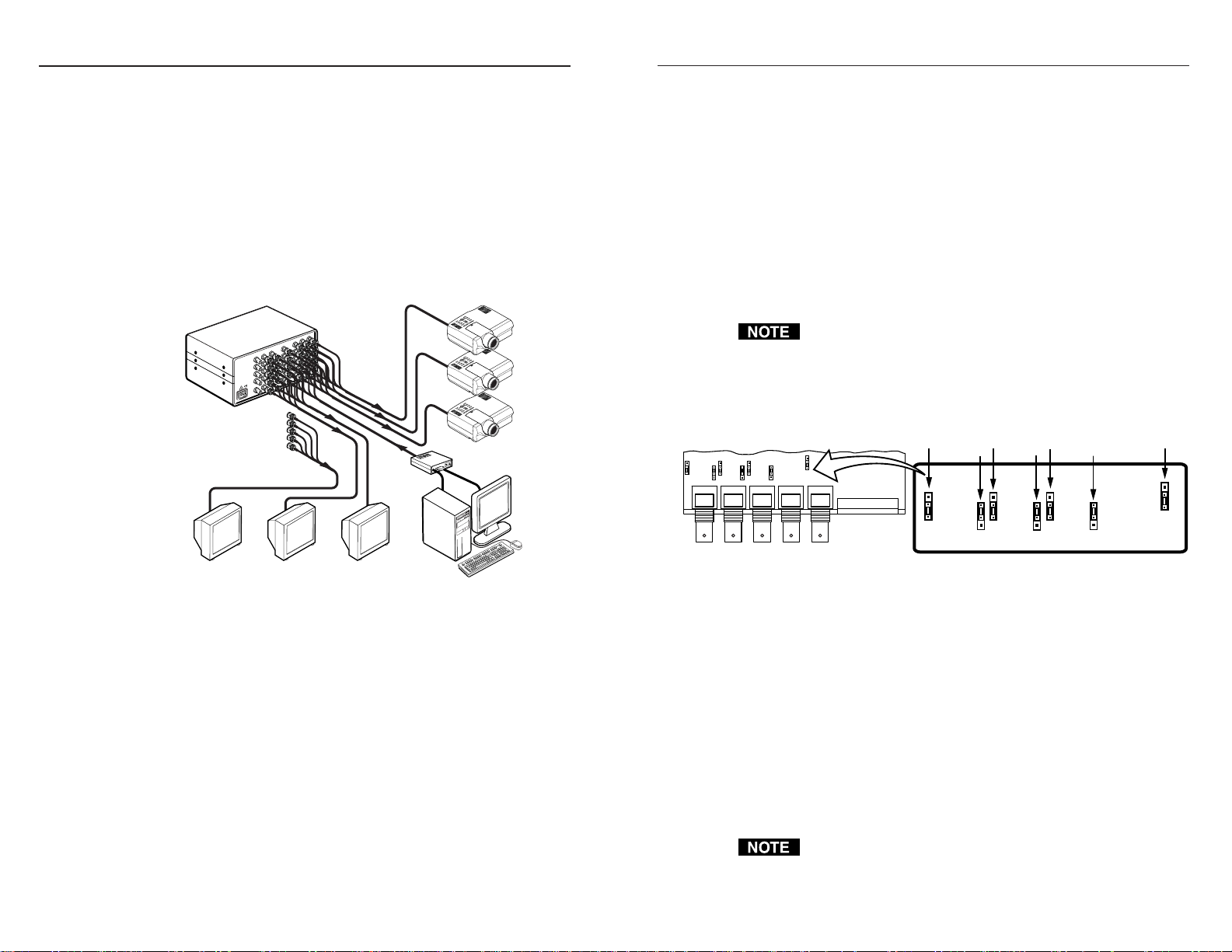
The illustration below is an example showing an ADA 6 distributing the
video from one source to six destinations. Two ADAs could be
connected together for a total of 11 outputs.
Features
• Accepts RGB with sync on green, separate composite sync, separate
H&V sync or NTSC/PAL video (certain models).
• High RGB bandwidth allows for signal distribution with no loss of
picture quality.
• Loop output for ganging units together to provide additional outputs
(certain models).
• All outputs are separately buffered and isolated.
• TTL or analog sync output selector switch allows you to choose
between output sync levels (sync gain).
Installation
To install an Extron ADA, do the following:
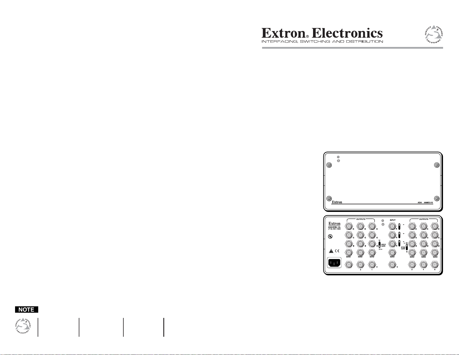
ADA 6 300 MX HV
Extron
Display Monitors
Interface
Hi-Res Workstation
Projectors
1. Remove power to the ADA and all computers and other devices
that will be connected during the installation procedure.
2. For rack mounting, first mount the ADA to a rack front panel, or
universal rack shelf, and then mount the assembly in the rack.
3. Connect the input BNC connectors to the signal source, such as
computer video through a video interface. Depending on the
model of your ADA, there are either four connectors (marked R, G,
B, and S) or five connectors (marked R, G, B, HV, and V).
4. Connect each output to its destination (such as a monitor or
projector).
5. Apply power to the ADA(s) and other devices, PC computer, local
monitor, and other display device(s).
If looping ADAs, choose which unit will be #1 and connect one of
its outputs to the input on ADA #2.
ADA 2 models, internal jumpers
Internal jumper settings for the ADA 2 300 HV model are shown below.
R G B H/HV V
Operation
There is little involved in the operation of an ADA. All models, except
for the ADA 2, have toggle switches on the rear panel. A small arrow
identifies the default position for each switch.
1. The Video Gain switch is normally set at 0.7V (down). For
installations with long output cable runs, the 1V (up) position will
give a better picture.
2. The Sync Gain switch is normally set at 4V (up), for TTL sync. For
the few applications where analog sync is used, this switch should
be in the 1V (down) position.
3. AC/DC coupling switches are normally set to the AC position.
Some applications may require that these switches be set to the DC
position.
If the Sync Gain switch is set for 1 V (down) when it should be at
4V, the result will be an unstable or blanking picture.
RED
GAIN
JUMP2
OFFSET
.7V 1V
DC AC
JUMP1
GREEN
GAIN
OFFSET
.7V 1V
DC AC
JUMP4 JUMP3
BLUE
GAIN
OFFSET
.7V 1V
JUMP6 JUMP5
SYNC
GAIN
4.OV 1.OV
DC AC
JUMP8
Analog Distribution Amplifiers • Features
1 2Analog Distribution Amplifiers • Installation and Operation1
Page 3

Operation
V
V
H
/
H
Y
-
Interface
Computer Source
Specifications
Video
Gain
ADA 2 300 MX/MX HV ..... Unity
ADA 4/6 300 MX/MX HV ... 0.7V or 1.0V, switch-selectable
Bandwidth
ADA 2 300 MX/MX HV ..... 400 MHz (-3dB), fully loaded
ADA 4/6 300 MX/MX HV ... 300 MHz (-3dB), fully loaded
Video input
Number/signal type
ADA 2/4/6 300 MX ........... 1 RGBS, RGsB, RsGsBs, component video, S-video,
ADA 2/4/6 300 MX HV ...... 1 RGBHV, RGBS, RGsB, RsGsBs, component video,
Connectors
ADA 2/4/6 300 MX ............ 4 BNC female
ADA 2/4/6 300 MX HV ...... 5 BNC female
Minimum/maximum levels ......... Analog ......... 0.3V to 1.5V p-p with no DC offset at
Impedance ........................................ 75 ohms
Horizontal frequency
ADA 2 300 MX/MX HV ..... 15 kHz to 135 kHz
ADA 4/6 300 MX/MX HV ... 15 kHz to 150 kHz
Vertical frequency
ADA 2 300 MX/MX HV ..... 30 Hz to 150 Hz
ADA 4/6 300 MX/MX HV ... 4 Hz to 140 Hz
Return loss
ADA 2 300 MX/MX HV ..... -42dB @ 5 MHz
ADA 4/6 300 MX/MX HV .. -38.5dB @ 5 MHz
AC/DC coupling ............................ Yes, switch-selectable
Analog Distribution Amplifiers • Operation
B
/
B
Y
/
G
Y
R
/
R
Extron
Power
ADA 2 300 HV
composite video
S-video, composite video
unity gain
2 Outputs
Specifications, cont’d
Video output
Number/signal type
ADA 2/4/6 300 MX ........... 2/4/6 RGBS, RGsB, RsGsBs, component video,
S-video, composite video
ADA 2/4/6 300 MX HV ...... 2/4/6 RGBHV, RGBS, RGsB, RsGsBs, component
video, S-video, composite video
Connectors
ADA 2/4/6 300 MX ........... 2/4/6 x 4 BNC female (depending on the model)
ADA 2/4/6 300 MX HV ...... 2/4/6 x 5 BNC female (depending on the model)
Minimum/maximum levels ......... 0.3V to 1.5V p-p
Impedance ........................................ 75 ohms
Return loss
ADA 2 300 MX/MX HV ..... -80dB @ 5 MHz
ADA 4/6 300 MX/MX HV ... -44dB @ 5 MHz
DC offset
ADA 2 300 MX/MX HV ..... ±5mV maximum, AC coupled
ADA 4/6 300 MX/MX HV ... ±13mV maximum with input at 0 offset
Sync
Input type ......................................... RGBHV (HV models only), RGBS, RGsB, RsGsBs
Output type ...................................... RGBHV (HV models only), RGBS, RGsB, RsGsBs
Input level ........................................ Analog or TTL ............................ 0.5V to 5V p-p
Output level
ADA 2 300 MX/MX HV ..... 5V p-p (TTL)
ADA 4 300 MX/MX HV ..... Analog or TTL (selectable) ....... 1.0V, 4.0V p-p
ADA 6 300 MX/MX HV ..... Analog or TTL (selectable) ...... 0.5V to 5V p-p
Gain ................................................... 1V or 4V p-p, switch-selectable
Input impedance
ADA 2 300 MX/MX HV ..... 510 ohms
ADA 4/6 300 MX/MX HV ... 500 ohms
Output impedance .......................... 75 ohms
Max input voltage ........................... 5V p-p
Input sensitivity .............................. 0.5V to 5.0V p-p
Max. propagation delay
ADA 2 300 MX/MX HV ..... 60 nS
ADA 4/6 300 MX/MX HV ... 34.8 nS
Max. rise/fall time
ADA 2 300 MX/MX HV ..... 4 nS
ADA 4/6 300 MX/MX HV .... 4.8 nS
Polarity ............................................. Positive or negative
General
Power
ADA 2 300 MX/ MX HV ..... 100VAC to 240 VAC, 50/60 Hz, 2 watts, external,
auto-switchable; to 9VDC, 1 A power supply.
All other models ................. 100VAC to 240VAC, 50/60 Hz, internal, auto-
switchable
Analog Distribution Amplifiers • Specifications
43
 Loading...