

Page 1

Included hardware
#60-141-01 — 2U panel for SW 6 Component and SW MX RGBS
switchers
4 machine screws (#10/32)
4 metal washers (#10)
#60-141-02 — 3U panel for SW MX RGBHV switchers
4 machine screws (#10/32)
4 metal washers (#10)
#60-030-10 — 2U panel for ADA RGBS and component
distribution amplifiers
4 machine screws (#10/32)
4 metal washers (#10)
8 nylon washers (#10)
#60-126-01 — 3U panel for ADA RGBHV distribution amplifiers
8 machine screws (#10/32)
8 metal washers (#10)
8 nylon washers (#10)
User’s Manual
Extron Electronics, USA
1230 South Lewis Street, Anaheim, CA 92805
800.633.9876 714.491.1500 FAX 714.491.1517
USA
© 2000 Extron Electronics. All rights reserved.
Extron Electronics, Europe
Beeldschermweg 6C, 3821 AH Amersfoort
+31.33.453.4040 FAX +31.33.453.4050
The Netherlands
Extron Electronics, Asia
135 Joo Seng Rd. #04-01, PM Industrial Bldg.
+65.383.4400 FAX +65.383.4664
Singapore 368363
Extron Electronics Information
ExtronWEB™: www.extron.com
ExtronFAX™: 714.491.0192
24-hour access—worldwide!
2U and 3U Rack Panels
P/N 60-141-01 – 2U – for SW 6 Component and SW MX RGBS Switchers
P/N 60-141-02 – 3U – for SW MX RGBHV Switchers
P/N 60-030-10 – 2U – for ADA RGBS and Component Distribution Amplifiers
P/N 60-126-01 – 3U – for ADA RGBHV Distribution Amplifiers
68-089-01 B
Printed in the USA
08 00
Page 2
Installation
This guide covers installation of four different rack panels –
a 2U and a 3U model for mounting Extron SW MX and
SW 6 Component switchers, and a 2U and a 3U model for
mounting Extron ADA distribution amplifiers. The switcher rack
panels have an area cut out for access to the front panel buttons,
and the ADA rack panels do not have cutouts.
Each of the four rack front panels ships with the following items:
• #10 nylon spacers for insertion between the mounting holes,
• #10 machine screws for mounting a device onto the rack panel,
• #10 beveled washers for mounting a device onto the panel.
Before installing the rack panel, consider the available space in
the rack, the devices that will be mounted on this panel, and their
cable runs.
A rack panel will accommodate two devices. The 2U panel
accepts RGBS and component video versions of these devices,
and the 3U panel accepts the RGBHV versions. Each of these
devices has four screws in its front panel. The screws will be
used to mount the device onto the rack panel.
The mounting holes in the rack panels and all the devices that can
be mounted to them are identically spaced. Therefore, a 2U
device and a 3U device can both be mounted on the same 3U
panel.
An ADA can be mounted on a switcher rack panel, but a
switcher cannot be mounted onto an ADA rack panel.
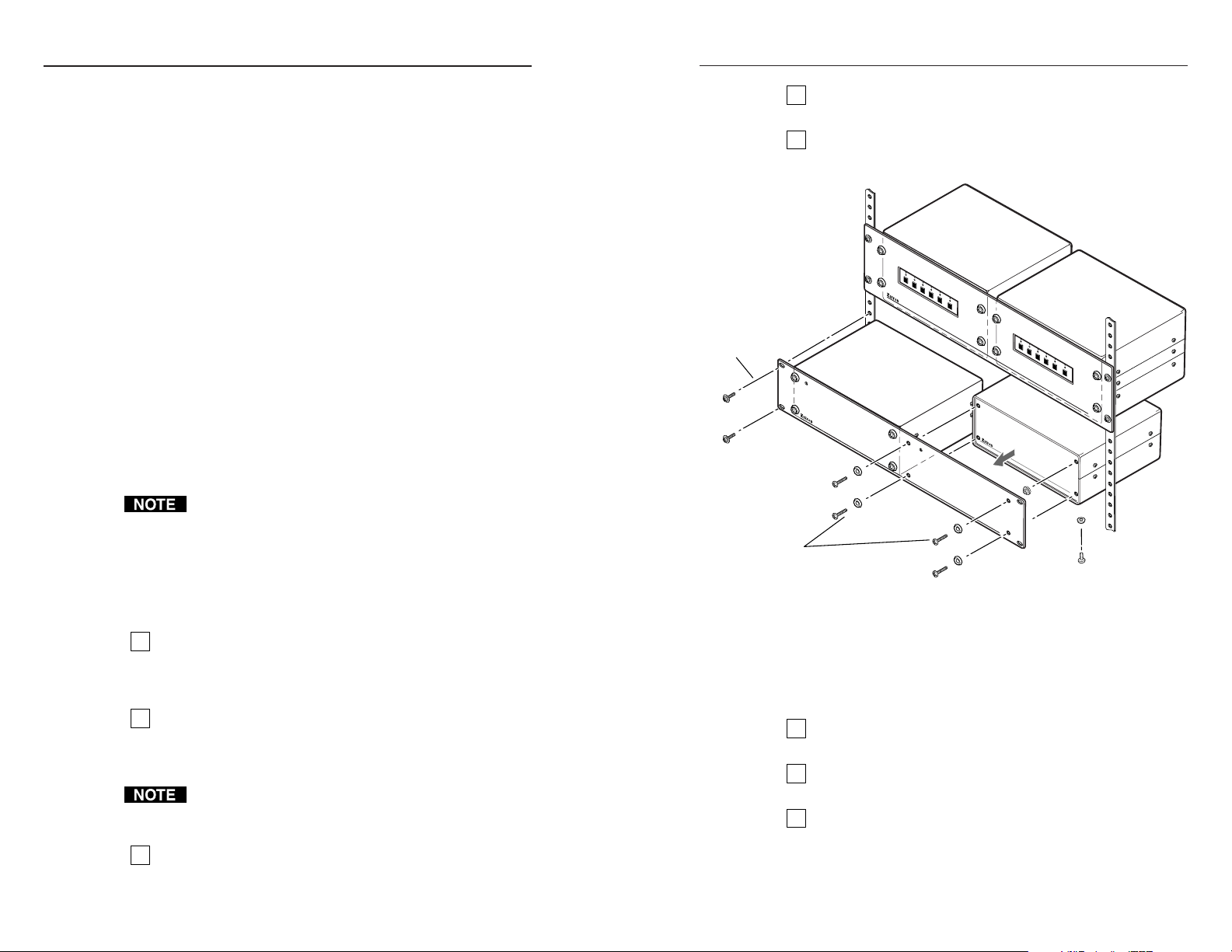
It is easiest to first attach the unit(s) to the rack panel, then install
the rack panel in the rack. See the illustration on the next page.
Installing an ADA/SW MX device onto a
2U or 3U rack panel
If the device being installed has rubber feet attached,
1
remove them. If left in place, these feet may interfere with
the device mounted below. Each foot is attached by a
Phillips-head screw.
Remove the four front panel screws (10/32 x 3/4”) and
2
beveled washers from the ADA/SW switcher. (These
screws are for rack mounting and do not hold the front
panel onto the unit.)
If the ADA or SW switcher model you are installing does
not come with holes predrilled for these four screws in its
front panel, it cannot be mounted on these rack panels.
Align the four rack panel holes with the four threaded
3
holes in the front of the device. Be sure there is a factoryinstalled nylon spacer in back of each rack panel hole.
Use four #10 washers and 10/32 screws to secure the
4
device onto the rack panel.
If a second device is being installed, repeat steps 1 through
5
4 to mount it onto the other half of the rack panel.
Attach panel
to rack
(4 places).
Remove front panel
screws & washers
from device (4 places).
Place screws through
washers, rack front panel,
& spacers, and into
the device (4 places).
The illustration above shows two SW6 AR MX HV switchers
installed on a 3U panel at the top, and two ADA4 300 MX
distribution amplifiers being installed on the 2U panel at the
bottom.
Installing the 2U or 3U rack panel in a rack
Use four 10/32 rack-mounting screws and washers to
1
mount the panel to the rack. See the illustration above.
After all the devices are mounted, connect input, output
2
and power cables to the devices.
Refer to the documentation that came with each device for
3
instructions on proper installation and operation.
Remove feet
(4 places).
2U and 3U Rack Panels • Installation2U and 3U Rack Panels • Installation
32
 Loading...