

Page 1
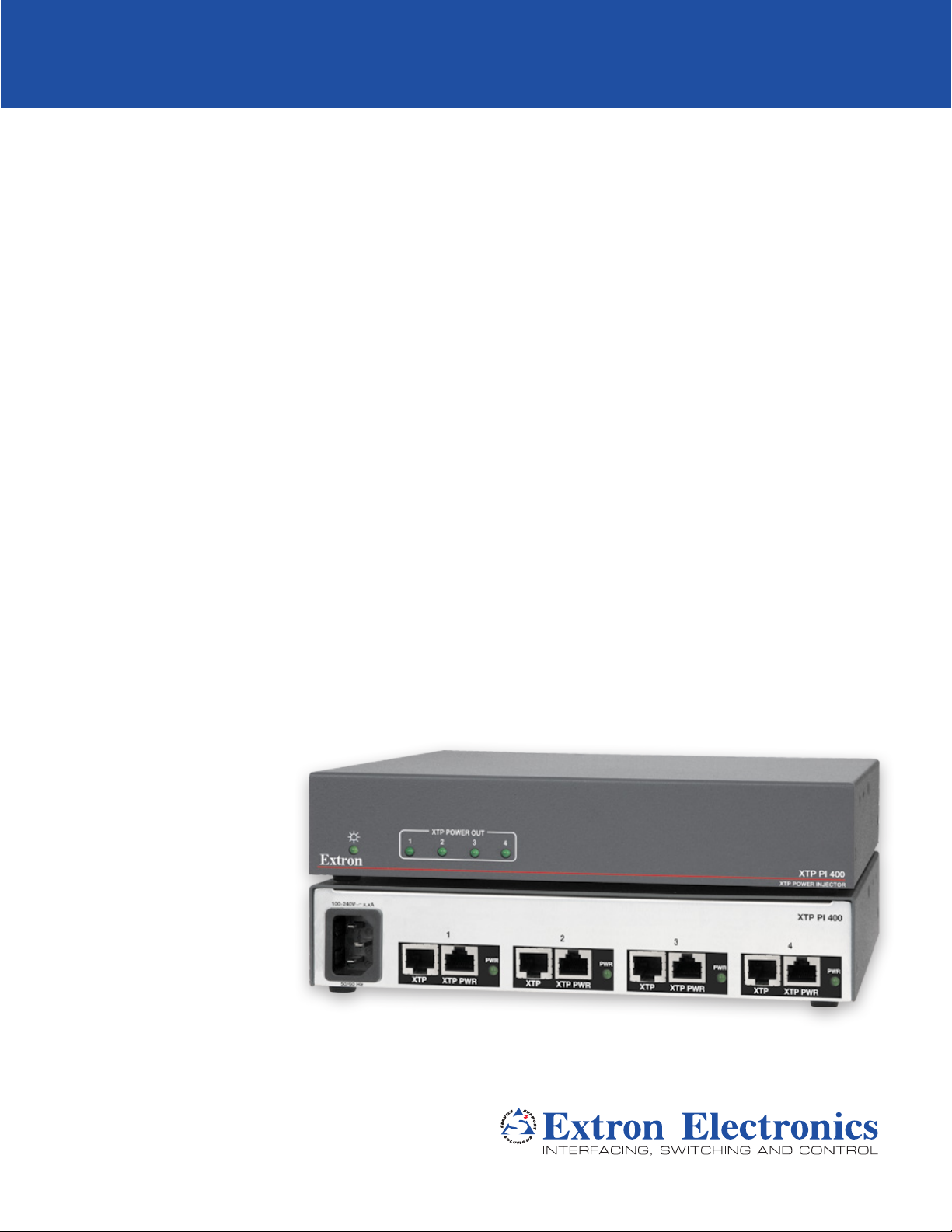
XTP PI 400
Four Port XTP Power Injector
User Guide
XTP Power Injector
68-2291-01 Rev. D
11 13
Page 2
Safety InstructionsSafety Instructions
Safety Instructions • English
WARNING: This symbol, , when used on the product, is intended to
alert the user of the presence of uninsulated dangerous voltage within the
product’s enclosure that may present a risk of electric shock.
ATTENTION: This symbol, , when used on the product, is intended
to alert the user of important operating and maintenance (servicing)
instructions in the literature provided with the equipment.
For information on safety guidelines, regulatory compliances, EMI/EMF
compatibility, accessibility, and related topics, see the Extron Safety and
Regulatory Compliance Guide, part number 68-290-01, on the Extron website,
www.extron.com.
Instructions de sécurité • Français
AVERTISSEMENT : Ce pictogramme, , lorsqu’il est utilisé sur le
produit, signale à l’utilisateur la présence à l’intérieur du boîtier du produit
d’une tension électrique dangereuse susceptible de provoquer un choc
électrique.
ATTENTION : Ce pictogramme, , lorsqu’il est utilisé sur le produit,
signale à l’utilisateur des instructions d’utilisation ou de maintenance
importantes qui se trouvent dans la documentation fournie avec le
matériel.
Pour en savoir plus sur les règles de sécurité, la conformité à la réglementation,
la compatibilité EMI/EMF, l’accessibilité, et autres sujets connexes, lisez les
informations de sécurité et de conformité Extron, réf. 68-290-01, sur le site
Extron, www.extron.com.
Sicherheitsanweisungen • Deutsch
WARNUNG: Dieses Symbol auf dem Produkt soll den Benutzer
darauf aufmerksam machen, dass im Inneren des Gehäuses dieses
Produktes gefährliche Spannungen herrschen, die nicht isoliert sind
und die einen elektrischen Schlag verursachen können.
Инструкция по технике безопасности • Русский
ПРЕДУПРЕЖДЕНИЕ: Данный символ, , если указан
на продукте, предупреждает пользователя о наличии
неизолированного опасного напряжения внутри корпуса
продукта, которое может привести к поражению
электрическим током.
ВНИМАНИЕ: Данный символ, , если указан на продукте,
предупреждает пользователя о наличии важных инструкций
по эксплуатации и обслуживанию в руководстве,
прилагаемом к данному оборудованию.
Для получения информации о правилах техники безопасности,
соблюдении нормативных требований, электромагнитной
совместимости (ЭМП/ЭДС), возможности доступа и других
вопросах см. руководство по безопасности и соблюдению
нормативных требований Extron на сайте Extron: www.extron.com,
номер по каталогу - 68-290-01.
Chinese Simplified(简体中文)
警告: 产品上的这个标志意在警告用户该产品机壳内有暴露的危险 电压,
有触电危险。
注意: 产品上的这个标志意在提示用户设备随附的用户手册中有
重要的操作和维护(维修)说明。
关于我们产品的安全指南、遵循的规范、EMI/EMF 的兼容性、无障碍
使用的特性等相关内容,敬请访问 Extron 网站 www.extron.com,参见
Extron 安全规范指南,产品编号 68-290-01。
Chinese Traditional( )
警告: 若產品上使用此符 號,是為了提醒使 用者,產品機殼內存在著
可能會導致觸電之風險的未絕緣危險電壓。
VORSICHT: Dieses Symbol auf dem Produkt soll dem Benutzer in der
im Lieferumfang enthaltenen Dokumentation besonders wichtige Hinweise
zur Bedienung und Wartung (Instandhaltung) geben.
Weitere Informationen über die Sicherheitsrichtlinien, Produkthandhabung,
EMI/EMF-Kompatibilität, Zugänglichkeit und verwandte Themen finden Sie in
den Extron-Richtlinien für Sicherheit und Handhabung (Artikelnummer
68-290-01) auf der Extron-Website, www.extron.com.
Instrucciones de seguridad • Español
ADVERTENCIA: Este símbolo, , cuando se utiliza en el producto,
avisa al usuario de la presencia de voltaje peligroso sin aislar dentro del
producto, lo que puede representar un riesgo de descarga eléctrica.
ATENCIÓN: Este símbolo, , cuando se utiliza en el producto, avisa
al usuario de la presencia de importantes instrucciones de uso y
mantenimiento recogidas en la documentación proporcionada con el
equipo.
Para obtener información sobre directrices de seguridad, cumplimiento
de normativas, compatibilidad electromagnética, accesibilidad y temas
relacionados, consulte la Guía de cumplimiento de normativas y seguridad de
Extron, referencia 68-290-01, en el sitio Web de Extron, www.extron.com.
注意 若產品上使用此符號,是為了提醒使用者,設備隨附的用戶手冊中有重
要的操作和維護(維修)説明。
有關安全性指導方針、法規遵守、EMI/EMF 相容性、存取範圍和相關主題的詳細資
訊,請瀏覽 Extron 網站:www.extron.com,然後參閱《Extron 安全性與法規
遵守手冊》,準則編號 68-290-01。
Japanese
警告: この記号 が製品上に表示されている場合は、筐体内に絶縁されて
いない高電圧が流れ、感電の危険があることを示しています。
注意: この記号 が製品上に表示されている場合は、本機の取扱説明書
に 記載さ れて いる重 要な操 作 と保 守 ( 整 備)の 指 示につ いてユーザ ー の 注
意を喚起するものです。
安全上のご注意、法規厳守、EMI/EMF適合性、その他の関連項目に
つ い て は 、エ ク スト ロン の ウ ェ ブ サ イト www.extron.com よ り 『 Extron Safety
and Regulatory Compliance Guide』 ( P/N 68-290-01) をご覧ください。
Korean
경고: 이 기호 가 제품에 사용될 경우, 제품의 인클로저 내에 있는
접지되지 않은 위험한 전류로 인해 사용자가 감전될 위험이 있음을
경고합니다.
주의: 이 기호 가 제품에 사용될 경우, 장비와 함께 제공된 책자에 나와
있는 주요 운영 및 유지보수(정비) 지침을 경고합니다.
안전 가이드라인, 규제 준수, EMI/EMF 호환성, 접근성, 그리고 관련 항목에
대한 자세한 내용은 Extron 웹 사이트(www.extron.com)의 Extron 안전 및
규제 준수 안내서, 68-290-01 조항을 참조하십시오.
Page 3

FCC Class A Notice
This equipment has been tested and found to comply with the limits for a Class A digital
device, pursuant to part15 of the FCC rules. The ClassA limits provide reasonable protection
against harmful interference when the equipment is operated in a commercial environment.
This equipment generates, uses, and can radiate radio frequency energy and, if not installed
and used in accordance with the instruction manual, may cause harmful interference to radio
communications. Operation of this equipment in a residential area is likely to cause interference.
This interference must be corrected at the expense of the user.
ATTENTION: The Twisted Pair Extension technology works with unshielded twisted
pair (UTP) or shielded twisted pair (STP) cables; but, to ensure FCC Class A and CE
compliance, STP cables and STP Connectors are required.
For more information on safety guidelines, regulatory compliances, EMI/EMF
compatibility, accessibility, and related topics, see the “Extron Safety and
Regulatory Compliance Guide” on the Extron website.
Copyright
© 2013 Extron Electronics. All rights reserved.
Trademarks
All trademarks mentioned in this guide are the properties of their respective owners.
The following registered trademarks®, registered service marks
RGBSystems, Inc. or Extron Electronics:
Registered Trademarks
AVTrac, Cable Cubby, CrossPoint, eBUS, EDID Manager, EDID Minder, Extron, Flat Field, GlobalViewer, Hideaway, Inline, IPIntercom,
IPLink, Key Minder, LockIt, MediaLink, PoleVault, PowerCage, PURE3, Quantum, SoundField, SpeedMount, SpeedSwitch, System
Integrator, TeamWork, TouchLink, V-Lock, VersaTools, VN-Matrix, VoiceLift, WallVault, WindoWall, XTP, and XTP Systems
Registered Service Mark
AAP, AFL (Accu-Rate Frame Lock), ADSP (Advanced Digital Sync Processing), AIS (Advanced Instruction Set), Auto-Image, CDRS (Class D
Ripple Suppression), DDSP (Digital Display Sync Processing), DMI (Dynamic Motion Interpolation), DriverConfigurator, DSPConfigurator,
DSVP (Digital Sync Validation Processing), FastBite, FOXBOX, IP Intercom HelpDesk, MAAP, MicroDigital, ProDSP, QS-FPC (QuickSwitch
Front Panel Controller), Scope-Trigger, SIS, Simple Instruction Set, Skew-Free, SpeedNav, Triple-Action Switching, XTRA, ZipCaddy,
ZipClip
(SM)
: S3 Service Support Solutions
Trademarks (™
(SM)
, and trademarks
(®)
)
(TM)
are the property of
Page 4

Conventions Used in this Guide
Notifications
The following notifications are used in this guide:
WARNING: A warning indicates a situation that has the potential to result in death or
severe injury.
ATTENTION: Attention indicates a situation that may damage or destroy the
product or associated equipment.
NOTE: A note draws attention to important information.
Specifications Availability
Product specifications are available on the Extron website, www.extron.com.
Page 5

Contents
Introduction ................................................... 1
About the XTP PI 400 ......................................... 1
Features ............................................................. 2
Installation and Operation ........................... 3
Installation .......................................................... 3
Important Safety Instructions .......................... 3
Rear Panel Connectors ................................... 5
Installation Overview ....................................... 5
Twisted Pair Cable Recommendations ............ 6
LED Indicators .................................................... 7
Reference Information ................................. 8
Mounting ............................................................ 8
Tabletop Mounting .......................................... 8
Under-the-table Mounting ............................... 8
Rack Mounting ............................................... 9
vXTP PI 400 Power Injector • Contents
Page 6

XTP PI 400 Power Injector • Contents vi
Page 7

Introduction
ACT LINK
XTP IN
XTP R HDMI
PS
Desk
Supply
XTP R HDMI
This guide contains information about the Extron XTP PI 400 Power Injector with instructions
for experienced installers on how to install, configure, and operate the equipment.
In this guide, the term “XTP PI 400” is used to refer to the XTP PI 400 Power Injector.
This section provides basic information about this guide, the XTP PI 400, and key features
of the XTP PI 400. Topics in this section include:
• About the XTP PI 400
• Features
About the XTP PI 400
The Extron XTP PI 400 is a four port power injector that provides power for up to four
remote XTP transmitters or receivers, eliminating the need for local power supplies.
Designed specifically for the high data rates of XTP systems, signal quality is unaffected
when using the power injector. It can be installed anywhere within the XTP signal path,
providing design flexibility for remote devices with limited space. To ensure quick and
dependable installation, the 1U, half rack width enclosure can be securely mounted using
Extron rack shelves. The XTP PI 400 power injector provides integration flexibility in XTP
systems with fully populated matrix switchers.
1210
top Power
Receiver
POWER
12V
XTP Signal
XTP PI 400
XTP Power Injector
POWER
12V
--A MAX
XTP T HDMI
Transmitter
XTP T HDMI
Transmitter
POWER
12V
--A MAX
HDMI
PS 1210
Desktop Power
Supply
100-240V x.xA
50/60 Hz
INPUTS
AUDIO
ON
LOOP-THRU
OFF
HDMI
Receiver
INPUTS
AUDIO
ON
OFF
LOOP-THRU
AUDIO
LR
−+−+
RS-232 IR
SIG LINK
OVER XTP
Rx GTx
RESET
ACT LINK
RxTx
XTP OUT
LAN
OVER XTP
RS-232 IR
ACT LINK
RxTx
Rx GTx
PS 1210
Desktop Power
OUTPUTS RELAYS
AUDIO
AUDIO
ON
OFF
HDMI
1
2
RL
-+-+
RESET
S/PDIF
Supply
AUDIO
LR
−+−+
RS-232 IR
XTP
OVER XTP
Rx GTx
1
XTP PWR2XTP
SIG LINK
ACT LINK
RxTx
XTP OUT
XTP Signal
PWR
XTP PWR3XTP
Remote Power
RESET
LAN
PWR
Remote Power
XTP IN
XTP Signal
PWR
XTP PWR4XTP
Remote Power
AUDIO
ON
OFF
RxTx
HDMI
AUDIO
-+-+
XTP PWR
OUTPUTS RELAYS
RL
S/PDIF
XTP PI 400
1
PWR
XTP T UWP 202
Transmitter
2
RESET
POWER
12V
1.0A MAX.
SIG LINK
RESET
RS-232
XTP OUT
TxRx
XTP R HDMI
Receiver
Figure 1. Typical XTP PI 400 Point-to-point Application
XTP PI 400 Power Injector • Introduction 1
Page 8

100-240V x.xA
50/60 Hz
1
XTP
PWR
XTP PWR2XTP
PWR
XTP PWR3XTP
PWR
XTP PWR4XTP
PWR
XTP PWR
XTP PI 400
POWER
12V
Rx GTx
RS-232 IR
RL
RxTx
-+-+
1
2
AUDIO
ON
AUDIO
RESET
ACT LINK
OVER XTP
OUTPUTS RELAYS
HDMI
OFF
S/PDIF
RL
RxTx
-+-+
1
2
AUDIO
ON
AUDIO
RESET
OUTPUTS RELAYS
XTP IN
HDMI
OFF
S/PDIF
ACT LINK
POWER
12V
HDMI
--A MAX
Rx GTx
RS-232 IR
RxTx
−+−+
LR
LOOP-THRU
RESET
AUDIO
OFF
ON
AUDIO
LAN
ACT LINK
SIG LINK
XTP OUT
INPUTS
OVER XTP
POWER
12V
HDMI
--A MAX
Rx GTx
RS-232 IR
RxTx
−+−+
LR
LOOP-THRU
RESET
AUDIO
OFF
ON
AUDIO
LAN
ACT LINK
SIG LINK
XTP OUT
INPUTS
OVER XTP
TxRx
RS-232
12V
1.0A MAX.
POWER
SIG LINK
XTP OUT
RESET
XTP Signal
XTP Signal
XTP Signal
XTP R HDMI
Receiver
XTP T HDMI
Transmitter
XTP T UWP 202
Transmitter
XTP R HDMI
Receiver
XTP PI 400
XTP Power Injector
PS 1210
Desktop Power
Supply
PS 1210
Desktop Power
Supply
PS 1210
Desktop Power
Supply
XTP R HDMI
Receiver
XTP T HDMI
Transmitter
Remote Power
Remote Power
Remote Power
XTP
XTP PWR
XTP CP 4i
IN
RS-232 IR
REMOTE
RS 232/RS422
RS-232 IR
IR/RS-232 OVER XTP
RS-232 IR
ACT
LAN
RS-232 IR
LINK
RESET
SIG LINK
PWR
SIG LINK
PWR
SIG LINK
100-240V
--A MAX
PWR
50-60Hz
SIG LINK
DISCONNECT POWER
CORD BEFORE
PWR
SERVICING
IN
IN
IN
IN
IN
IN
TxRx Tx Rx
TxRx Tx Rx
TxRx Tx Rx
TxRx Tx Rx
TxRx Tx Rx
TxRx Tx Rx
TxRx Tx Rx
TxRx Tx Rx
LAN
ACT LINK
XTP
LAN
ACT LINK
XTP
LAN
ACT LINK
XTP
LAN
ACT LINK
XTP
RS-232 IR
RS-232 IR
RS-232 IR
RS-232 IR
RS-232 IR
TxRx Tx Rx
TxRx Tx Rx
TxRx Tx Rx
TxRx Tx Rx
RS-232 IR
RS-232 IR
RS-232 IR
RS-232 IR
RS-232 IR
IR/RS-232 OVER XTP
IR/RS-232 OVER XTP
IR/RS-232 OVER XTP
IR/RS-232 OVER XTP
IR/RS-232 OVER XTP
TxRx Tx Rx
TxRx Tx Rx
TxRx Tx Rx
TxRx Tx Rx
RS-232 IR
RS-232 IR
RS-232 IR
RS-232 IR
RS-232 IR
TxRx Tx Rx
TxRx Tx Rx
TxRx Tx Rx
TxRx Tx Rx
RS-232 IR
RS-232 IR
RS-232 IR
RS-232 IR
RS-232 IR
LAN
LAN
LAN
LAN
ACT LINK
ACT LINK
ACT LINK
ACT LINK
XTP
XTP
XTP
XTP
SIG LINK
SIG LINK
SIG LINK
SIG LINK
SIG LINK
PWR
PWR
PWR
PWR
PWR
LAN
LAN
LAN
LAN
ACT LINK
ACT LINK
ACT LINK
ACT LINK
XTP
XTP
XTP
XTP
SIG LINK
SIG LINK
SIG LINK
SIG LINK
SIG LINK
PWR
PWR
PWR
PWR
PWR
LAN
LAN
LAN
LAN
ACT LINK
ACT LINK
ACT LINK
ACT LINK
XTP
XTP
XTP
XTP
SIG LINK
SIG LINK
SIG LINK
SIG LINK
SIG LINK
PWR
PWR
PWR
PWR
PWR
LAN
LAN
LAN
LAN
ACT LINK
ACT LINK
ACT LINK
ACT LINK
XTP
XTP
XTP
XTP
SIG LINK
SIG LINK
SIG LINK
SIG LINK
SIG LINK
PWR
PWR
PWR
PWR
PWR
IN
IN
IN
IN
IN
XTP CP 4o
IN
IN
OUT
TxRx Tx Rx
TxRx Tx Rx
TxRx Tx Rx
RS-232 IR
TxRx Tx Rx
RS-232 IR
IR/RS-232 OVER XTP
TxRx Tx Rx
RS-232 IR
TxRx Tx Rx
RS-232 IR
LAN
ACT LINK
XTP
SIG LINK
LAN
ACT LINK
XTP
SIG LINK
LAN
ACT LINK
XTP
SIG LINK
LAN
ACT LINK
XTP
SIG LINK
IN
TxRx Tx Rx
RS-232 IR
RS-232 IR
TxRx Tx Rx
TxRx Tx Rx
TxRx Tx Rx
RS-232 IR
RS-232 IR
IR/RS-232 OVER XTP
IR/RS-232 OVER XTP
TxRx Tx Rx
TxRx Tx Rx
TxRx Tx Rx
RS-232 IR
RS-232 IR
TxRx Tx Rx
TxRx Tx Rx
TxRx Tx Rx
RS-232 IR
RS-232 IR
LAN
LAN
LAN
ACT LINK
ACT LINK
ACT LINK
O
I
U
XTP
XTP
XTP
N
T
SIG LINK
SIG LINK
P
P
PWR
PWR
PWR
U
U
T
T
S
S
LAN
LAN
LAN
ACT LINK
ACT LINK
ACT LINK
XTP
XTP
XTP
SIG LINK
SIG LINK
PWR
PWR
PWR
LAN
LAN
LAN
ACT LINK
ACT LINK
ACT LINK
XTP
XTP
XTP
SIG LINK
SIG LINK
PWR
PWR
PWR
LAN
LAN
LAN
ACT LINK
ACT LINK
ACT LINK
XTP
XTP
XTP
SIG LINK
SIG LINK
PWR
PWR
PWR
IN
OUT
XTP Signal
Extron
XTP CrossPoint 3200
XTP CP 4o
XTP CP 4o
XTP CP 4o
XTP CP 4o
XTP CP 4o
XTP CP 4o
XTP CP 4o
OUT
OUT
OUT
OUT
OUT
OUT
OUT
RS-232 IR
RS-232 IR
IR/RS-232 OVER XTP
RS-232 IR
RS-232 IR
SIG LINK
PWR
SIG LINK
PWR
SIG LINK
PWR
SIG LINK
PWR
OUT
TxRx Tx Rx
TxRx Tx Rx
TxRx Tx Rx
TxRx Tx Rx
TxRx Tx Rx
TxRx Tx Rx
TxRx Tx Rx
RS-232 IR
RS-232 IR
RS-232 IR
RS-232 IR
RS-232 IR
RS-232 IR
TxRx Tx Rx
TxRx Tx Rx
TxRx Tx Rx
TxRx Tx Rx
TxRx Tx Rx
TxRx Tx Rx
TxRx Tx Rx
RS-232 IR
RS-232 IR
RS-232 IR
RS-232 IR
RS-232 IR
RS-232 IR
IR/RS-232 OVER XTP
IR/RS-232 OVER XTP
IR/RS-232 OVER XTP
IR/RS-232 OVER XTP
IR/RS-232 OVER XTP
IR/RS-232 OVER XTP
TxRx Tx Rx
TxRx Tx Rx
TxRx Tx Rx
TxRx Tx Rx
TxRx Tx Rx
TxRx Tx Rx
TxRx Tx Rx
RS-232 IR
RS-232 IR
RS-232 IR
RS-232 IR
RS-232 IR
RS-232 IR
TxRx Tx Rx
TxRx Tx Rx
TxRx Tx Rx
TxRx Tx Rx
TxRx Tx Rx
TxRx Tx Rx
TxRx Tx Rx
RS-232 IR
RS-232 IR
RS-232 IR
RS-232 IR
RS-232 IR
RS-232 IR
LAN
LAN
LAN
LAN
LAN
LAN
LAN
ACT LINK
ACT LINK
ACT LINK
ACT LINK
ACT LINK
ACT LINK
ACT LINK
XTP
XTP
XTP
XTP
XTP
XTP
XTP
SIG LINK
SIG LINK
SIG LINK
SIG LINK
SIG LINK
SIG LINK
PWR
PWR
PWR
PWR
PWR
PWR
LAN
LAN
LAN
LAN
LAN
LAN
LAN
ACT LINK
ACT LINK
ACT LINK
ACT LINK
ACT LINK
ACT LINK
ACT LINK
XTP
XTP
XTP
XTP
XTP
XTP
XTP
SIG LINK
SIG LINK
SIG LINK
SIG LINK
SIG LINK
SIG LINK
PWR
PWR
PWR
PWR
PWR
PWR
LAN
LAN
LAN
LAN
LAN
LAN
LAN
ACT LINK
ACT LINK
ACT LINK
ACT LINK
ACT LINK
ACT LINK
ACT LINK
XTP
XTP
XTP
XTP
XTP
XTP
XTP
SIG LINK
SIG LINK
SIG LINK
SIG LINK
SIG LINK
SIG LINK
PWR
PWR
PWR
PWR
PWR
PWR
LAN
LAN
LAN
LAN
LAN
LAN
LAN
ACT LINK
ACT LINK
ACT LINK
ACT LINK
ACT LINK
ACT LINK
ACT LINK
XTP
XTP
XTP
XTP
XTP
XTP
XTP
SIG LINK
SIG LINK
SIG LINK
SIG LINK
SIG LINK
SIG LINK
PWR
PWR
PWR
PWR
PWR
PWR
OUT
OUT
OUT
OUT
OUT
OUT
XTP Signal
XTP CP 4i
XTP CP 4i
XTP CP 4i
XTP CP 4i
XTP CP 4i
XTP CP 4i
XTP CP 4i
Features
POWER
12V
1.0A MAX.
XTP T UWP 202
Transmitter
SIG LINK
RS-232
XTP OUT
TxRx
XTP PI 400
XTP Power Injector
RESET
POWER
12V
--A MAX
1
XTP T USW 103
XTP Transmitter
Remote Power
INPUTS
2
100-240V x.xA
XTP
50/60 Hz
SIG LINK
OVER XTP
AUDIO
3
RS-232 IR
ACT LINK
RxTx
XTP OUT
LAN
1
PWR
XTP PWR2XTP
Remote Power
XTP T USW 103
CONTACT
RS-232
RESET
1 2 3
RxTx
Tx Rx
PWR
XTP PWR3XTP
XTP PI 400
PWR
XTP PWR4XTP
XTP PWR
Remote Power
POWER
12V
--A MAX
XTP SR HDMI
XTP Scaling Receiver
PWR
Remote Power
SIG LINK
POWER
12V
--A MAX
ACT LINK
XTP IN
LAN
XTP SR HDMI
XTP Scaling Receiver
SIG LINK
ACT LINK
XTP IN
LAN
OUTPUTS
OVER XTP
HDMI AUDIO
ON
RS-232 IR
OFF
HDMI
RxTx
RxTx
AUDIO
LR
−+−+
OVER XTP
RS-232 IR
RxTx
S/PDIF
S/PDIF
HDMI AUDIO
AUDIO
RELAYS
ON
OFF
HDMI
RxTx
XTP SR HDMI
RELAYS
REMOTE
1
2
RS-232
Tx Rx
REMOTE
1
2
RS-232
LR
RESET
−+−+
Tx Rx
RESET
XTP SR HDMI
OUTPUTS
Figure 2. Typical XTP PI 400 Matrix Application
• Supplies power for up to four remote XTP extenders — Provides power for up to
four XTP transmitters or receivers over the XTP link, eliminating the need for local power
supplies.
• Designed specifically for the high data rates of XTP systems
• No impact on signal quality — Utilization of the power injector does not affect video,
audio, bidirectional RS-232 and IR, and Ethernet signal quality.
• Real-time status LEDs for troubleshooting and monitoring — Front and rear
indicators provide status for each port that is supplying power to an XTP extender.
• UL/c-UL Listed and CE compliant
• 1U, half rack width enclosure
• Internal universal power supply — The 100-240 VAC, 50-60 Hz, international power
supply provides worldwide power compatibility.
XTP PI 400 Power Injector • Introduction 2
Page 9

Installation and Operation
This section contains installation procedures and operation features. Topics in this section
include:
• Installation
• LED Indicators
Installation
Important Safety Instructions
This symbol, when used on the product, is intended to alert the user of important
operating and maintenance (servicing) instructions in the literature provided with the
equipment.
This symbol, when used on the product, is intended to alert the user of the presence
of uninsulated dangerous voltage within the product enclosure that may present a
risk of electric shock.
• Read these instructions.
• Keep these instructions.
• Heed all warnings.
• Follow all instructions.
• Do not use this apparatus near water.
• Clean only with dry cloth.
• Do not block any ventilation openings. Install in accordance with the manufacturer’s
instructions.
• Do not install near any heat sources such as radiators, heat registers, stoves, or other
apparatus (including amplifiers) that produce heat.
• Do not defeat the safety purpose of the polarized or grounding-type plug. A polarized plug
has two blades with one wider than the other. A grounding type plug has two blades and
a third grounding prong. The wide blade or the third prong are provided for your safety. If
the provided plug does not fit into your outlet, consult an electrician for replacement of the
obsolete outlet.
• Protect the power cord from being walked on or pinched particularly at plugs, convenience
receptacles, and the point where they exit from the apparatus.
• Only use attachments and accessories specified by the manufacturer.
• Unplug this device apparatus during lightning storms or when unused for long periods
of time.
XTP PI 400 Power Injector • Installation and Operation 3
Page 10

WARNING: Risk of electrical shock. To reduce the risk of fire or electric shock, do
not expose this apparatus to rain, moisture, dripping, splashing, or objects filled with
liquids.
Refer all servicing to qualified service personnel. Servicing is required when the apparatus
has been damaged in any way, such as when the power supply cord or plug is damaged,
liquid has been spilled or objects have fallen into the apparatus, the apparatus has been
exposed to rain or moisture, does not operate normally, or has been dropped.
ATTENTION: This apparatus is a Class I product. This product must be connected to
a mains socket outlet with a protective earthing connection.
The mains plug is used as the disconnect device and must remain readily operable.
WARNING: To prevent the risk of shock, do not attempt to service this equipment
yourself because opening or removing covers may expose you to dangerous voltage
or other hazards.
ATTENTION:
• Power sources — This equipment should be operated only from the power
source indicated on the product. This equipment is intended to be used with a
main power system with a grounded (neutral) conductor. The third (grounding) pin
is a safety feature. Do not attempt to bypass or disable it.
• Power disconnection — To remove power from the equipment safely, remove
all power cords from the rear of the equipment, or the desktop power module (if
detachable), or from the power source receptacle (wall plug).
XTP PI 400 Power Injector • Installation and Operation 4
Page 11

Rear Panel Connectors
bb bbcccc
INCORRECT
100-240V x.xA
50/60 Hz
1
XTP
PWR
XTP PWR2XTP
PWR
XTP PWR3XTP
PWR
XTP PWR4XTP
PWR
XTP PWR
XTP PI 400
POWER
12V
--A MAX
Rx GTx
RS-232 IR
RL
RxTx
-+-+
1
2
AUDIO
ON
AUDIO
RESET
LAN
ACT LINK
OVER XTP
OUTPUTS RELAYS
SIG LINK
XTP IN
HDMI
OFF
S/PDIF
CATx
XTP R HDMI
XTP PI 400
XTP Power Injector
CATx
POWER
12V
HDMI
--A MAX
Rx GTx
RS-232 IR
RxTx
−+−+
LR
LOOP-THRU
RESET
AUDIO
OFF
ON
AUDIO
LAN
ACT LINK
SIG LINK
XTP OUT
INPUTS
OVER XTP
CATx
XTP T HDMI
Transmitter
Remote Power
Remote Power
Receiver
100-240V 1.6 A
50/60 Hz
XTP
1
XTP PWR
PWR
XTP
2
XTP PWR
PWR
XTP
3
PWR
XTP PWR
XTP
XTP PI 400
4
PWR
XTP PWR
Figure 3. Rear Panel Features
ATTENTION: Do not connect these devices to a computer data or telecommunications
network.
NOTE: The XTP PI 400 does not switch XTP signals.
AC power connector — Connect the IEC power cord to the AC power connector.
a
XTP connector — Connect an Extron XTP device that is powered by a local power
b
source to the XTP connector on any of the four port pairs.
XTP PWR connector — Connect an Extron XTP device that requires power from an
c
external source to the XTP PWR connector. Make sure there is an XTP device plugged
into the XTP connector on the same port pair.
NOTE: Do not loop XTP port pairs on a single cable run to remotely power the
transmitter and receiver. Figure 5, below, shows this type of application, which is not
recommended by Extron.
INPUTS
POWER
12V
--A MAX
XTP T HDMI
Transmitter
100-240V x.xA
50/60 Hz
HDMI
XTP
AUDIO
LOOP-THRU
CATx
Remote Power
1
PWR
XTP PWR2XTP
CATx
SIG LINK
POWER
12V
XTP R HDMI
Receiver
OVER XTP
RS-232 IR
--A MAX
ACT LINK
Rx GTx
LAN
XTP IN
Figure 4. Correct application
SIG LINK
OVER XTP
AUDIO
LR
RS-232 IR
ON
OFF
−+−+
ACT LINK
RxTx
Rx GTx
XTP OUT
LAN
PWR
XTP PWR3XTP
OUTPUTS RELAYS
AUDIO
AUDIO
1
RL
ON
OFF
RxTx
-+-+
HDMI
S/PDIF
CORRECT
RESET
PWR
XTP PWR4XTP
XTP PWR
XTP PI 400
XTP Power Injector
2
RESET
XTP PI 400
XTP T HDMI
Transmitter
PWR
• Figure 5. Incorrect application
INPUTS
POWER
12V
--A MAX
HDMI
LOOP-THRU
100-240V x.xA
1
XTP
XTP PWR2XTP
50/60 Hz
CATx
INCORRECT
AUDIO
ON
OFF
CATx
Remote Power
PWR
OVER XTP
AUDIO
LR
RS-232 IR
−+−+
Rx GTx
XTP PWR3XTP
SIG LINK
ACT LINK
RxTx
XTP OUT
LAN
PWR
XTP PWR4XTP
CATx
Remote Power
RESET
XTP PI 400
PWR
XTP PWR
XTP PI 400
XTP Power Injector
SIG LINK
POWER
12V
--A MAX
ACT LINK
LAN
XTP IN
XTP R HDMI
PWR
OVER XTP
RS-232 IR
Rx GTx
OUTPUTS RELAYS
AUDIO
AUDIO
1
2
RL
ON
OFF
RxTx
HDMI
RESET
-+-+
S/PDIF
Installation Overview
1. Mount the device in a rack, under a table, or on a tabletop (see Mounting on page 8).
2. Connect a locally powered XTP device
to the XTP connector on one of the port
pairs.
3. On the same port pair, connect an
XTP device that requires power from
an external source to the XTP PWR
connector.
4. Repeat steps 2 and 3 for each XTP port
pair as necessary.
5. Connect AC power to the XTP PI 400.
XTP PI 400 Power Injector • Installation and Operation 5
To an XTP Device To an XTP Device
XTP
PWR
XTP PWR
that Requires an
External Power Supply
Page 12

Twisted Pair Cable Recommendations
12345678
RJ-45
Connector
Insert Twisted
Pair Wires
Pins:
Pin
1
2
3
4
5
6
7
8
Wire color
White-green
Green
White-orange
Blue
White-blue
Orange
White-brown
Brown
Wire color
T568A T568B
White-orange
Orange
White-green
Blue
White-blue
Green
White-brown
Brown
Use the following pin configurations for twisted pair cables.
TIA/EIA-T568B
Pin Wire Color
1 White-orange
2 Orange
3 White-green
4 Blue
5 White-blue
6 Green
7 White-brown
8 Brown
Figure 6. Twisted Pair Cable Configuration
Supported cables
The XTP PI 400 is compatible with CAT 5e, 6, 6a, and 7 shielded twisted pair
(F/UTP, SF/UTP, and S/FTP) and unshielded twisted pair (U/UTP) cable.
ATTENTION:
• Do not use Extron UTP23SF-4 Enhanced Skew-Free AV UTP cable or STP201
cable.
• To ensure FCC Class A and CE compliance, STP cables and STP connectors are
required.
Cable recommendations
Extron recommends using the following practices to achieve full transmission distances up
to 330 feet (100 m) and reduce transmission errors:
• Use the following Extron XTP DTP 24 SF/UTP cables and connectors for the best
performance:
• XTP DTP 24/1000 Non-plenum 1000 feet (305 m) spool 22-236-03
• XTP DTP 24P/1000 Plenum 1000 feet (305 m) spool 22-235-03
• XTP DTP 24 Plug Package of 10 101-005-02
• If you are not using XTP DTP 24 cable, at a minimum Extron recommends 24 AWG,
solid conductor, STP cable with a minimum bandwidth of 400 MHz.
• Terminate cables with shielded connectors to the TIA/EIA-T568B standard.
• Limit the use of more than two pass-through points, which may include patch points,
punch down connectors, couplers, and power injectors. If these pass-through points
are required, use CAT 6 or 6a shielded couplers and punch down connectors.
NOTE: Using more than three patches with the XTP PI 400 yields varying maximum
cable lengths.
Number of Patches Maximum Transmission Distance
1 or 2 330 ft (100 m)
3 280 ft (85 m)
NOTES: When using CAT 5e or CAT 6 cable in bundles or conduits:
• Do not exceed 40% fill capacity in conduits.
• Do not comb the cable for the first 20 m where cables are straightened, aligned,
and secured in tight bundles.
• Loosely place cables and limit the use of tie wraps or hook-and-loop fasteners.
• Separate twisted pair cables from AC power cables.
XTP PI 400 Power Injector • Installation and Operation 6
Page 13

LED Indicators
ab
X
c
XTP POWER OUT
1
2 3 4
XTP POWER INJECTOR
Figure 7. Front Panel Features
Front panel power LED indicator — Lights to indicate the XTP PI 400 is receiving
a
power.
Front panel XTP Power Out LED indicators — Light when the XTP PI 400 is
b
providing power to XTP devices connected to the XTP PWR connectors.
NOTE: If the last connected XTP device that requires power draws more power
than the XTP PI 400 can provide, the corresponding XTP Power Out LED
indicator blinks, indicating the output cannot be powered due to the over power
draw. Disconnect the XTP device to correct the issue.
XTP PI 400
Rear panel Pwr LED indicators — Light or blink to indicate the various power states
c
of the XTP device connected to the corresponding XTP PWR connector (see the table
below for LED states).
LED State Port Status
Unlit The endpoint is not connected or cannot
be powered.
Lit The endpoint is receiving power from the
XTP PI 400.
XTP
TP Port
XTP PWR
PWR
Blinks five times There is a power overload fault.
Blinks nine times The power allocation is exceeded.
XTP PI 400 Power Injector • Installation and Operation 7
Page 14

Reference Information
Mounting
The XTP PI 400 is 1U high and one half rack wide.
ATTENTION:
• The XTP PI 400 is not suitable for use in air handling spaces or in wall cavities. The
power supply must be located within the vicinity of the Extron AV equipment in an
ordinary location with pollution degree 2, and secured to an equipment rack within
a dedicated closet, podium, or desk.
The installation must be in accordance with the applicable provisions of National
Electrical Code ANSI/NFPA 70, article 75 and Canadian Electrical Code part 1,
section 16. The power supply must not be permanently fixed to building or similar
structure.
• This device is for intra-building use only.
1. Turn off or disconnect all equipment power sources.
2. Mount the XTP PI 400 on a table, on a rack shelf, or under a desk using an optional
mounting kit.
WARNING: Risk of electrical shock. To reduce the risk of fire or electric shock, do
not expose this apparatus to rain, moisture, dripping, splashing, or objects filled with
liquids.
Tabletop Mounting
Attach the provided rubber feet to the bottom four corners of the enclosure.
Under-the-table Mounting
Use an optional Extron mounting kit to mount the XTP PI 400 under a desk or table. Follow
the instructions included with the kit.
XTP PI 400 Power Injector • Reference Information 8
Page 15

Rack Mounting
r
Half Rack 9.5 inch Box Standard Shelf
Mount the XTP PI 400 to an optional Extron rack shelf. To mount the unit on a rack shelf,
follow the instructions provided with the shelf accessories.
Front false
faceplate uses
2 screws.
1U Universal Rack Shelf
Use 2 mounting holes on
opposite corners.
1/2 Rack Width Front False
Faceplate
(2) 4-40 x 3/16"
Screws
NOTE: Using screws longe
than 3/16" will damage the
unit and void the warranty.
Figure 8. Half Rack Mounting
UL Guidelines for Rack Mounted Devices
The following Underwriters Laboratories (UL) guidelines pertain to the safe installation of the
XTP PI 400 in a rack.
1. Elevated operating ambient temperature — If the equipment is installed in a closed
or multi-unit rack assembly, the operating ambient temperature of the rack environment
may be greater than room ambient temperature. Therefore, install the XTP PI 400 in an
environment compatible with the maximum ambient temperature
(Tma = +122 ˚F, +50 ˚C) specified by Extron.
2. Reduced air flow — Install the equipment in a rack so that the amount of air flow
required for safe operation of the equipment is not compromised.
3. Mechanical loading — Mount the equipment in the rack so that uneven mechanical
loading does not cause a hazardous condition.
4. Circuit overloading — Connect the equipment to the supply circuit and consider the
effect that circuit overloading might have an overcurrent protection and supply wiring.
Appropriate consideration of equipment nameplate ratings should be used when
addressing this concern.
5. Reliable earthing (grounding) — Maintain reliable grounding of rack-mounted
equipment. Pay particular attention to supply connections other than direct connections
to the branch circuit (for example, use of power strips).
XTP PI 400 Power Injector • Reference Information 9
Page 16

Extron Warranty
Extron Electronics warrants this product against defects in materials and workmanship for a period of three years
from the date of purchase. In the event of malfunction during the warranty period attributable directly to faulty
workmanship and/or materials, Extron Electronics will, at its option, repair or replace said products or components,
to whatever extent it shall deem necessary to restore said product to proper operating condition, provided that it is
returned within the warranty period, with proof of purchase and description of malfunction to:
USA, Canada, South America,
and Central America:
Extron Electronics
1230 South Lewis Street
Anaheim, CA 92805
U.S.A.
Europe and Africa:
Extron Europe
Hanzeboulevard 10
3825 PH Amersfoort
The Netherlands
Japan:
Extron Electronics, Japan
Kyodo Building, 16 Ichibancho
Chiyoda-ku, Tokyo 102-0082
Japan
China:
Extron China
686 Ronghua Road
Songjiang District
Shanghai 201611
China
Asia:
Extron Asia Pte Ltd
135 Joo Seng Road, #04-01
PM Industrial Bldg.
Singapore 368363
Middle East:
Extron Middle East
Dubai Airport Free Zone
F12, PO Box 293666
United Arab Emirates, Dubai
Singapore
This Limited Warranty does not apply if the fault has been caused by misuse, improper handling care, electrical
or mechanical abuse, abnormal operating conditions, or if modifications were made to the product that were not
authorized by Extron.
NOTE: If a product is defective, please call Extron and ask for an Application Engineer to receive an RA (Return
Authorization) number. This will begin the repair process.
USA: 714.491.1500 or 800.633.9876 Europe: 31.33.453.4040
Asia: 65.6383.4400 Japan: 81.3.3511.7655
Units must be returned insured, with shipping charges prepaid. If not insured, you assume the risk of loss or damage
during shipment. Returned units must include the serial number and a description of the problem, as well as the
name of the person to contact in case there are any questions.
Extron Electronics makes no further warranties either expressed or implied with respect to the product and its quality,
performance, merchantability, or fitness for any particular use. In no event will Extron Electronics be liable for direct,
indirect, or consequential damages resulting from any defect in this product even if Extron Electronics has been
advised of such damage.
Please note that laws vary from state to state and country to country, and that some provisions of this warranty may
not apply to you.
Extron Headquarters
+1.800.633.9876 (Inside USA/Canada Only)
Extron USA - West Extron USA - East
+1.714.491.1500 +1.919.850.1000
+1.714.491.1517 FAX +1.919.850.1001 FAX
Extron Europe
+800.3987.6673
(Inside Europe Only)
+31.33.453.4040
+31.33.453.4050 FAX
© 2013 Extron Electronics All rights reserved. www.extron.com
Extron Asia
+65.6383.4400
+65.6383.4664 FAX
Extron Japan
+81.3.3511.7655
+81.3.3511.7656 FAX
Extron China
+86.21.3760.1568
+86.21.3760.1566 FAX
Extron Middle East
+971.4.299.1800
+971.4.299.1880 FAX
Extron Korea
+82.2.3444.1571
+82.2.3444.1575 FAX
Extron India
1800.3070.3777
(Inside India Only)
+91.80.3055.3777
+91.80.3055.3737 FAX
 Loading...