

Page 1
IMPORTANT:
100-240V x.xA
50/60 Hz
1
XTP
PWR
XTP PWR
2
XTP
PWR
XTP PWR
3
XTP
PWR
XTP PWR
4
XTP
PWR
XTP PWR
XTP PI 400
1
XTP POWER OUT
XTP PI 400
XTP POWER INJECTOR
2 3 4
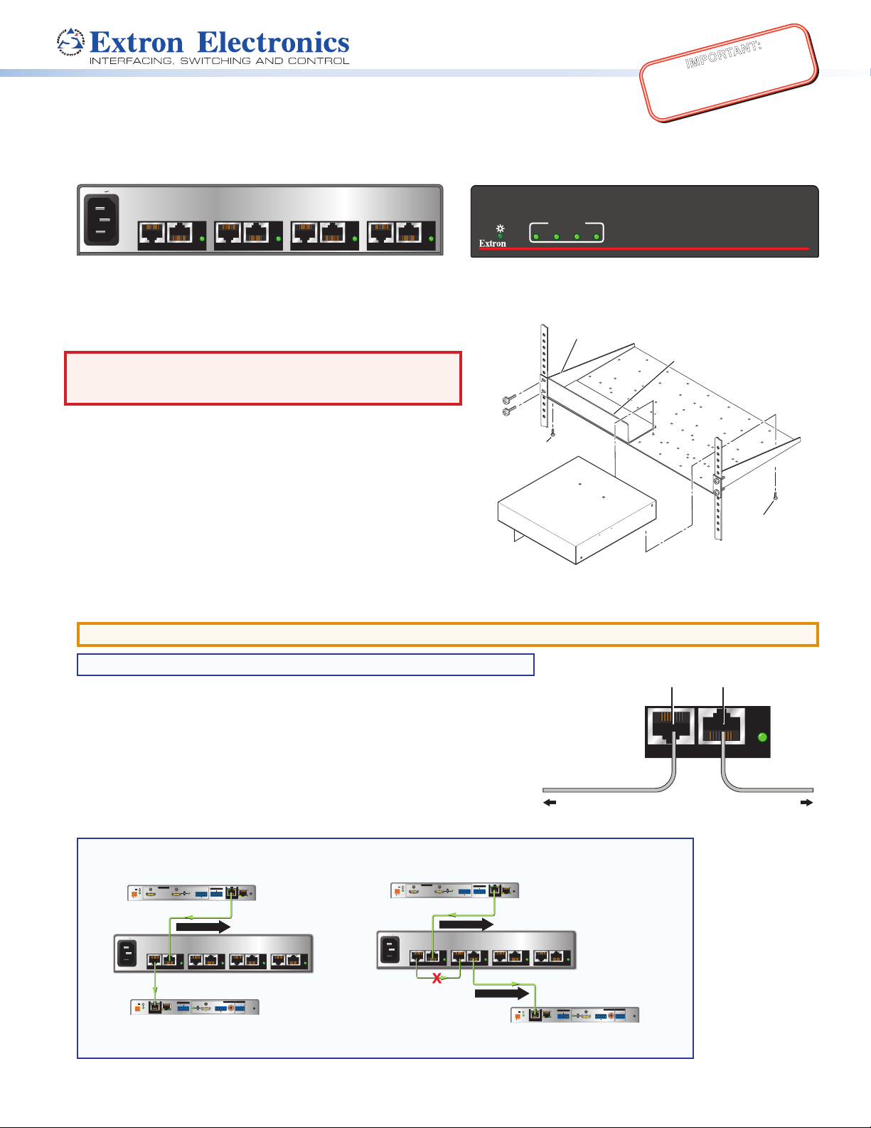
Rear Panel
Front Panel
ws longer
Half Rack 9.5 inch Box Standard Shelf
ÇÉ
INCORRECT
100-240V x.xA
50/60 Hz
1
XTP
PWR
XTP PWR2XTP
PWR
XTP PWR3XTP
PWR
XTP PWR4XTP
PWR
XTP PWR
XTP PI 400
POWER
12V
--A MAX
Rx GTx
RS-232 IR
RL
RxTx
-+-+
1
2
AUDIO
ON
AUDIO
RESET
LAN
ACT LINK
OVER XTP
OUTPUTS RELAYS
SIG LINK
XTP IN
HDMI
OFF
S/PDIF
CATx
XTP R HDMI
XTP PI 400
XTP Power Injector
CATx
POWER
12V
HDMI
--A MAX
Rx GTx
RS-232 IR
RxTx
−+−+
LR
LOOP-THRU
RESET
AUDIO
OFF
ON
AUDIO
LAN
ACT LINK
SIG LINK
XTP OUT
INPUTS
OVER XTP
CATx
XTP T HDMI
Transmitter
Remote Power
Remote Power
Receiver
Go to www.extron.com for the complete
user guide, installation instructions, and
XTP PI 400 Power Injector • Setup Guide
specifications before connecting the
product to the power source.
The Extron XTP PI 400 Power Injector is a midspan power injector for XTP products. It provides power over LAN for up to four
XTP endpoints. This guide provides instructions for an experienced installer to install and connect the XTP PI 400.
Installation
RSU 129 Universal Rack Shelf
WARNING: Risk of electrical shock. To reduce the risk of
re or electric shock, do not expose this apparatus to rain,
moisture, dripping, splashing, or objects lled with liquids.
Step 1— Mounting
Front false
The XTP PI 400 is 1U high and one-half rack wide.
a. Turn off or disconnect all equipment power sources.
faceplate
uses 2
screws.
b. Mount the XTP PI 400 in a rack shelf (see the image to the right) or
under a desk using an optional mounting kit.
Use 2 mounting holes on
opposite corners.
Step 2 — Cabling
ATTENTION: Do not connect this device to a computer data or telecommunications network.
NOTE: The XTP PI 400 does not switch XTP signals.
For the best performance, see Twisted Pair Cable Termination and
Recommendations on page 2.
a. Using a CATx cable, connect an Extron XTP device to the XTP connector on
one of the four port pairs. The XTP device plugged into this connector must
be powered by a local power source.
b. Using a CATx cable, connect an XTP device that requires power from an
external source to the XTP Pwr connector.
c. Repeat steps 2a and 2b for each XTP port pair as necessary.
NOTE: Do not loop XTP port pairs on a single cable run to remotely power the transmitter and receiver.
Figure 2, below, shows this type of application, which is not recommended by Extron.
AUDIO
LR
RS-232 IR
−+−+
XTP PWR3XTP
SIG LINK
OVER XTP
ACT LINK
RxTx
Rx GTx
XTP OUT
LAN
PWR
CATx
Remote Power
RESET
XTP PWR4XTP
POWER
12V
--A MAX
XTP R HDMI
INPUTS
POWER
12V
--A MAX
XTP T HDMI
Transmitter
100-240V x.xA
50/60 Hz
POWER
12V
--A MAX
XTP R HDMI
Receiver
Figure 1. Correct Application
d. Connect AC power to the XTP PI 400.
HDMI
XTP
SIG LINK
XTP IN
LOOP-THRU
Remote Power
1
PWR
XTP PWR2XTP
CATx
OVER XTP
RS-232 IR
ACT LINK
Rx GTx
LAN
AUDIO
ON
OFF
CATx
SIG LINK
OVER XTP
AUDIO
LR
RS-232 IR
−+−+
ACT LINK
RxTx
Rx GTx
XTP OUT
LAN
PWR
XTP PWR3XTP
OUTPUTS RELAYS
AUDIO
AUDIO
1
2
RL
ON
OFF
RxTx
-+-+
HDMI
S/PDIF
CORRECT
RESET
XTP PI 400
PWR
XTP PWR4XTP
XTP PWR
XTP PI 400
XTP Power Injector
RESET
PWR
INPUTS
POWER
12V
--A MAX
XTP T HDMI
Transmitter
100-240V x.xA
50/60 Hz
INCORRECT
Figure 2. Incorrect Application
AUDIO
ON
OFF
HDMI
LOOP-THRU
CATx
Remote Power
1
PWR
XTP
XTP PWR2XTP
CATx
To an XTP Device To an XTP Device
XTP PI 400
PWR
PWR
XTP PWR
XTP PI 400
XTP Power Injector
SIG LINK
OVER XTP
RS-232 IR
ACT LINK
Rx GTx
LAN
XTP IN
OUTPUTS RELAYS
AUDIO
AUDIO
1
2
RL
ON
OFF
RxTx
HDMI
RESET
-+-+
S/PDIF
1/2 Rack Width Front False
Faceplate
NOTE: Using scre
than 3/16" will damage the
unit and void the warranty.
XTP
XTP PWR
that Requires an
External Power Supply
(2) 4-40 x 3/16"
Screws
PWR
1
Page 2

XTP PI 400 Power Injector • Setup Guide (Continued)
12345678
RJ-45
Connector
Insert Twisted
Pair Wires
Pins:
Pin
1
2
3
4
5
6
7
8
Wire color
White-green
Green
White-orange
Blue
White-blue
Orange
White-brown
Brown
Wire color
T568A T568B
White-orange
Orange
White-green
Blue
White-blue
Green
White-brown
Brown
XTP PI 400
XTP POWER INJECTOR
Front Panel
ab
c
Features
Indicators
Front panel power LED indicator — Lights to indicate the XTP PI 400 is receiving
a
power.
Front panel XTP Power Out LED indicators — Light when the XTP PI 400 is
b
providing power to XTP endpoints.
NOTE: If the last connected endpoint draws more power than the XTP PI 400
can provide, the corresponding XTP Power Out LED indicator blinks, indicating
the output cannot be powered because too much power is being drawn from
the XTP PI 400. Disconnect the endpoint to correct the issue.
Rear panel Pwr LED indicators — Light or blink to indicate various power states
c
of the connected endpoints (see the table below for LED states).
XTP POWER OUT
1
2 3 4
PWR
LED State Port Status
XTP
XTP PWR
Unlit The endpoint is not connected or cannot be powered.
Lit The endpoint is receiving power from the XTP PI 400.
Blinks ve times There is a power overload fault.
Blinks nine times The power allocation is exceeded.
NOTE: Blinking LEDs repeat the number of blinks specified in the table above after a short interval of remaining unlit.
Twisted Pair Cable Termination and Recommendations
Use the following pin conguration for twisted pair cables.
TIA/EIA T568B
Pin Wire Color
1 White-orange
2 Orange
3 White-green
4 Blue
5 White-blue
6 Green
7 White-brown
8 Brown
Figure 3. Twisted Pair Cable Configuration
Supported cables
The XTP PI 400 is compatible with CAT 5e, 6, 6a, and 7 shielded twisted pair (F/UTP, SF/UTP, and S/FTP) and unshielded twisted
pair (U/UTP) cable.
ATTENTION:
• Do not use Extron UTP23SF-4 Enhanced Skew-Free AV UTP cable or STP201 cable.
• To ensure FCC Class A and CE compliance, STP cables and STP connectors are required.
Cable recommendations
Extron recommends using the following practices to achieve full transmission distances up to 330 feet (100 m) and reduce
transmission errors.
z Use the following Extron XTP DTP 24 SF/UTP cables and connectors for the best performance:
z If you are not using XTP DTP 24 cable, at a minimum Extron recommends 24 AWG, solid conductor, STP cable with a
2
z XTP DTP 24/1000 Non-plenum 1000 feet (305 m) spool 22-236-03
z XTP DTP 24P/1000 Plenum 1000 feet (305 m) spool 22-235-03
z XTP DTP 24 Plug Package of 10 101-005-02
minimum bandwidth of 400 MHz.
Page 3

z Terminate cables with shielded connectors to the TIA/EIA T568B standard.
SIG LINK
XTP R HDMI
Receiver
PS
Desk
Supply
z Limit the use of more than two pass-through points, which may include patch points, punch down connectors, couplers, and
power injectors. If these pass-through points are required, use CAT 6 or 6a shielded couplers and punch down connectors.
NOTE: Using more than three patches with the XTP PI 400 yields varying maximum cable lengths. Limit the use of RJ-45
patches in the system.
Number of Patches Maximum Transmission Distance
1 or 2 330 ft. (100 m)
3 280 ft. (85 m)
NOTE: When using CAT 5e or CAT 6 cable in bundles or conduits:
• Do not exceed 40% ll capacity in conduits.
• Do not comb the cables for the rst 20 m, where cables are straightened, aligned, and secured in tight bundles.
• Loosely place cables and limit the use of tie wraps or hook and loop fasteners.
• Separate twisted pair cables from AC power cables.
Applications
The XTP PI 400 can provide remote power to XTP extenders in a point-to-point installation (see gure 4). It can also provide
power to XTP endpoints with an XTP matrix (see figure 5 on the next page).
1210
top Power
Receiver
POWER
12V
--A MAX
SIG LINK
XTP IN
ACT LINK
LAN
OVER XTP
RS-232 IR
Rx GTx
XTP Signal
XTP PI 400
XTP Power Injector
AUDIO
ON
OFF
RxTx
HDMI
XTP T HDMI
Transmitter
POWER
12V
--A MAX
HDMI
PS 1210
Desktop Power
Supply
OUTPUTS RELAYS
AUDIO
RL
-+-+
INPUTS
100-240V x.xA
50/60 Hz
S/PDIF
LOOP-THRU
XTP R HDMI
Receiver
1
2
RESET
AUDIO
AUDIO
LR
ON
OFF
−+−+
OVER XTP
RS-232 IR
Rx GTx
SIG LINK
RESET
ACT LINK
RxTx
XTP OUT
LAN
SIG LINK
POWER
12V
--A MAX
XTP IN
ACT LINK
LAN
OVER XTP
RS-232 IR
Rx GTx
AUDIO
ON
OFF
RxTx
HDMI
PS 1210
AUDIO
-+-+
OUTPUTS RELAYS
RL
S/PDIF
1
2
RESET
Desktop Power
Supply
XTP Signal
XTP Signal
XTP PI 400
1
PWR
XTP
XTP PWR
2
PWR
XTP
XTP PWR
3
PWR
XTP
XTP PWR
4
PWR
XTP
XTP PWR
POWER
12V
--A MAX
INPUTS
AUDIO
AUDIO
LR
ON
OFF
HDMI
LOOP-THRU
−+−+
OVER XTP
RS-232 IR
Rx GTx
SIG LINK
RxTx
XTP OUT
XTP T HDMI
Transmitter
Figure 4. Typical XTP PI 400 Point-to-point Application
Remote Power
RESET
ACT LINK
LAN
XTP R HDMI
SIG LINK
XTP IN
Remote Power
Remote Power
POWER
12V
1.0A MAX.
XTP T UWP 202
RS-232
TxRx
SIG LINK
XTP OUT
RESET
Transmitter
OVER XTP
AUDIO
RS-232 IR
ON
ACT LINK
LAN
OFF
RxTx
Rx GTx
HDMI
AUDIO
-+-+
OUTPUTS RELAYS
RL
S/PDIF
1
2
RESET
3
Page 4

LAN
100-240V
DISCONNECT POWER
CORD BEFORE
XTP CP 4i
REMOTE
RS 232/RS422
IR/RS-232 OVER XTP
ACT
LINK
RESET
SIG LINK
SIG LINK
SIG LINK
--A MAX
50-60Hz
SIG LINK
SERVICING
IN
IN
IN
IN
TxRx Tx Rx
RS-232 IR
TxRx Tx Rx
RS-232 IR
TxRx Tx Rx
RS-232 IR
TxRx Tx Rx
RS-232 IR
LAN
ACT LINK
PWR
LAN
ACT LINK
PWR
LAN
ACT LINK
PWR
LAN
ACT LINK
PWR
IN
TxRx Tx Rx
TxRx Tx Rx
TxRx Tx Rx
RS-232 IR
RS-232 IR
RS-232 IR
TxRx Tx Rx
TxRx Tx Rx
TxRx Tx Rx
RS-232 IR
RS-232 IR
RS-232 IR
IR/RS-232 OVER XTP
IR/RS-232 OVER XTP
IR/RS-232 OVER XTP
IR/RS-232 OVER XTP
TxRx Tx Rx
TxRx Tx Rx
TxRx Tx Rx
RS-232 IR
RS-232 IR
RS-232 IR
TxRx Tx Rx
TxRx Tx Rx
TxRx Tx Rx
RS-232 IR
RS-232 IR
RS-232 IR
LAN
LAN
LAN
ACT LINK
ACT LINK
ACT LINK
XTP
XTP
XTP
XTP
XTP
XTP
XTP
SIG LINK
SIG LINK
SIG LINK
SIG LINK
PWR
PWR
PWR
LAN
LAN
LAN
ACT LINK
ACT LINK
ACT LINK
XTP
XTP
XTP
SIG LINK
SIG LINK
SIG LINK
SIG LINK
PWR
PWR
PWR
LAN
LAN
LAN
ACT LINK
ACT LINK
ACT LINK
XTP
XTP
XTP
SIG LINK
SIG LINK
SIG LINK
SIG LINK
PWR
PWR
PWR
LAN
LAN
LAN
ACT LINK
ACT LINK
ACT LINK
XTP
XTP
XTP
SIG LINK
SIG LINK
SIG LINK
SIG LINK
PWR
PWR
PWR
IN
IN
IN
IN
IN
IN
IN
IN
RS-232 IR
RS-232 IR
RS-232 IR
RS-232 IR
PWR
PWR
PWR
PWR
TxRx Tx Rx
TxRx Tx Rx
TxRx Tx Rx
TxRx Tx Rx
RS-232 IR
RS-232 IR
RS-232 IR
TxRx Tx Rx
TxRx Tx Rx
TxRx Tx Rx
TxRx Tx Rx
RS-232 IR
RS-232 IR
RS-232 IR
IR/RS-232 OVER XTP
IR/RS-232 OVER XTP
IR/RS-232 OVER XTP
TxRx Tx Rx
TxRx Tx Rx
TxRx Tx Rx
TxRx Tx Rx
RS-232 IR
RS-232 IR
RS-232 IR
TxRx Tx Rx
TxRx Tx Rx
TxRx Tx Rx
TxRx Tx Rx
RS-232 IR
RS-232 IR
RS-232 IR
LAN
LAN
LAN
LAN
ACT LINK
ACT LINK
ACT LINK
ACT LINK
XTP
SIG LINK
LAN
ACT LINK
XTP
SIG LINK
LAN
ACT LINK
XTP
SIG LINK
LAN
ACT LINK
XTP
SIG LINK
IN
I
XTP
XTP
XTP
N
SIG LINK
SIG LINK
P
PWR
PWR
PWR
U
T
S
LAN
LAN
LAN
ACT LINK
ACT LINK
ACT LINK
XTP
XTP
XTP
SIG LINK
SIG LINK
PWR
PWR
PWR
LAN
LAN
LAN
ACT LINK
ACT LINK
ACT LINK
XTP
XTP
XTP
SIG LINK
SIG LINK
PWR
PWR
PWR
LAN
LAN
LAN
ACT LINK
ACT LINK
ACT LINK
XTP
XTP
XTP
SIG LINK
SIG LINK
PWR
PWR
PWR
IN
IN
XTP CP 4o
XTP CP 4o
XTP CP 4o
OUT
OUT
TxRx Tx Rx
TxRx Tx Rx
RS-232 IR
RS-232 IR
TxRx Tx Rx
TxRx Tx Rx
RS-232 IR
RS-232 IR
IR/RS-232 OVER XTP
IR/RS-232 OVER XTP
TxRx Tx Rx
TxRx Tx Rx
RS-232 IR
RS-232 IR
TxRx Tx Rx
TxRx Tx Rx
RS-232 IR
RS-232 IR
LAN
LAN
ACT LINK
ACT LINK
O
U
XTP
XTP
T
SIG LINK
SIG LINK
SIG LINK
P
PWR
PWR
U
T
S
LAN
LAN
ACT LINK
ACT LINK
XTP
XTP
SIG LINK
SIG LINK
SIG LINK
PWR
PWR
LAN
LAN
ACT LINK
ACT LINK
XTP
XTP
SIG LINK
SIG LINK
SIG LINK
PWR
PWR
LAN
LAN
ACT LINK
ACT LINK
XTP
XTP
SIG LINK
SIG LINK
SIG LINK
PWR
PWR
OUT
OUT
XTP CP 4o
XTP CP 4o
XTP CP 4o
OUT
OUT
OUT
TxRx Tx Rx
TxRx Tx Rx
RS-232 IR
RS-232 IR
TxRx Tx Rx
TxRx Tx Rx
RS-232 IR
RS-232 IR
IR/RS-232 OVER XTP
IR/RS-232 OVER XTP
IR/RS-232 OVER XTP
TxRx Tx Rx
TxRx Tx Rx
RS-232 IR
RS-232 IR
TxRx Tx Rx
TxRx Tx Rx
RS-232 IR
RS-232 IR
LAN
LAN
ACT LINK
ACT LINK
XTP
XTP
SIG LINK
SIG LINK
PWR
PWR
LAN
LAN
ACT LINK
ACT LINK
XTP
XTP
SIG LINK
SIG LINK
PWR
PWR
LAN
LAN
ACT LINK
ACT LINK
XTP
XTP
SIG LINK
SIG LINK
PWR
PWR
LAN
LAN
ACT LINK
ACT LINK
XTP
XTP
SIG LINK
SIG LINK
PWR
PWR
OUT
OUT
OUT
XTP CP 4o
XTP CP 4o
OUT
OUT
OUT
TxRx Tx Rx
TxRx Tx Rx
RS-232 IR
TxRx Tx Rx
RS-232 IR
TxRx Tx Rx
RS-232 IR
TxRx Tx Rx
RS-232 IR
LAN
ACT LINK
XTP
PWR
LAN
ACT LINK
XTP
PWR
LAN
ACT LINK
XTP
PWR
LAN
ACT LINK
XTP
PWR
TxRx Tx Rx
TxRx Tx Rx
RS-232 IR
RS-232 IR
RS-232 IR
TxRx Tx Rx
TxRx Tx Rx
TxRx Tx Rx
RS-232 IR
RS-232 IR
RS-232 IR
IR/RS-232 OVER XTP
IR/RS-232 OVER XTP
IR/RS-232 OVER XTP
TxRx Tx Rx
TxRx Tx Rx
TxRx Tx Rx
RS-232 IR
RS-232 IR
RS-232 IR
TxRx Tx Rx
TxRx Tx Rx
TxRx Tx Rx
RS-232 IR
RS-232 IR
RS-232 IR
LAN
LAN
LAN
ACT LINK
ACT LINK
ACT LINK
XTP
XTP
XTP
SIG LINK
SIG LINK
SIG LINK
PWR
PWR
PWR
LAN
LAN
LAN
ACT LINK
ACT LINK
ACT LINK
XTP
XTP
XTP
SIG LINK
SIG LINK
SIG LINK
PWR
PWR
PWR
LAN
LAN
LAN
ACT LINK
ACT LINK
ACT LINK
XTP
XTP
XTP
SIG LINK
SIG LINK
SIG LINK
PWR
PWR
PWR
LAN
LAN
LAN
ACT LINK
ACT LINK
ACT LINK
XTP
XTP
XTP
SIG LINK
SIG LINK
SIG LINK
PWR
PWR
PWR
OUT
OUT
OUT
XTP CP 4i
XTP CP 4i
XTP CP 4i
XTP CP 4i
XTP CP 4i
XTP CP 4i
XTP CP 4i
XTP Signal
XTP PI 400
XTP Power Injector
POWER
12V
1.0A MAX.
SIG LINK
RESET
RS-232
XTP OUT
TxRx
XTP T UWP 202
Transmitter
POWER
12V
--A MAX
XTP T USW 103
XTP Transmitter
Figure 5. Typical XTP PI 400 Matrix Application
Remote Power
INPUTS
2
1
3
Extron
XTP CrossPoint 3200
100-240V x.xA
1
PWR
XTP
ACT LINK
LAN
XTP PWR2XTP
Remote Power
XTP T USW 103
OVER XTP
CONTACT
RS-232 IR
RS-232
1 2 3
RxTx
RxTx
Tx Rx
RESET
50/60 Hz
SIG LINK
AUDIO
XTP OUT
XTP PWR
XTP Signal
XTP PI 400
PWR
PWR
XTP
XTP PWR
3
4
PWR
XTP
XTP PWR
Remote Power
SIG LINK
POWER
12V
--A MAX
XTP IN
ACT LINK
OVER XTP
RS-232 IR
RxTx
LAN
OUTPUTS
HDMI AUDIO
AUDIO
ON
LR
OFF
HDMI
RxTx
−+−+
XTP SR HDMI
S/PDIF
RELAYS
REMOTE
1
2
RS-232
RESET
Tx Rx
XTP SR HDMI
Remote Power
POWER
12V
--A MAX
XTP Scaling Receiver
SIG LINK
XTP IN
ACT LINK
OVER XTP
HDMI AUDIO
ON
RS-232 IR
OFF
RxTx
RxTx
LAN
OUTPUTS
AUDIO
LR
HDMI
−+−+
XTP SR HDMI
S/PDIF
RELAYS
REMOTE
1
2
RS-232
RESET
Tx Rx
XTP SR HDMI
XTP Scaling Receiver
Extron Headquarters
+800.633.9876 Inside USA/Canada Only
Extron USA - West Extron USA - East
+1.714.491.1500 +1.919.850.1000
+1.714.491.1517 FAX +1.919.850.1001 FAX
© 2013 Extron Electronics All rights reserved. All trademarks mentioned are the property of their respective owners. www.extron.com
4
Extron Europe
+800.3987.6673
Inside Europe Only
+31.33.453.4040
+31.33.453.4050 FAX
Extron Asia
+65.6383.4400
+65.6383.4664 FAX
Extron Japan
+81.3.3511.7655
+81.3.3511.7656 FAX
Extron China
+86.21.3760.1568
+86.21.3760.1566 FAX
Extron
Middle East
+971.4.299.1800
+971.4.299.1880 FAX
Extron Korea
+82.2.3444.1571
+82.2.3444.1575 FAX
Extron India
1800.3070.3777
Inside India Only
+91.80.3055.3777
+91.80.3055.3737 FAX
68-2291-50
Rev. E
11 13
 Loading...